EP2448340B1 - Method and device for establishing uplink synchronization - Google Patents
Method and device for establishing uplink synchronization Download PDFInfo
- Publication number
- EP2448340B1 EP2448340B1 EP09846332.6A EP09846332A EP2448340B1 EP 2448340 B1 EP2448340 B1 EP 2448340B1 EP 09846332 A EP09846332 A EP 09846332A EP 2448340 B1 EP2448340 B1 EP 2448340B1
- Authority
- EP
- European Patent Office
- Prior art keywords
- serving base
- base station
- timing information
- base stations
- transmission
- Prior art date
- Legal status (The legal status is an assumption and is not a legal conclusion. Google has not performed a legal analysis and makes no representation as to the accuracy of the status listed.)
- Not-in-force
Links
Images


Classifications
-
- H—ELECTRICITY
- H04—ELECTRIC COMMUNICATION TECHNIQUE
- H04W—WIRELESS COMMUNICATION NETWORKS
- H04W56/00—Synchronisation arrangements
-
- H—ELECTRICITY
- H04—ELECTRIC COMMUNICATION TECHNIQUE
- H04W—WIRELESS COMMUNICATION NETWORKS
- H04W56/00—Synchronisation arrangements
- H04W56/004—Synchronisation arrangements compensating for timing error of reception due to propagation delay
- H04W56/0045—Synchronisation arrangements compensating for timing error of reception due to propagation delay compensating for timing error by altering transmission time
-
- H—ELECTRICITY
- H04—ELECTRIC COMMUNICATION TECHNIQUE
- H04W—WIRELESS COMMUNICATION NETWORKS
- H04W92/00—Interfaces specially adapted for wireless communication networks
- H04W92/04—Interfaces between hierarchically different network devices
- H04W92/10—Interfaces between hierarchically different network devices between terminal device and access point, i.e. wireless air interface
Definitions
- the present invention relates to wireless communication technology, and more particularly to a method and device for implementing uplink synchronization.
- Uplink (UL) Coordinated Multiple Points has been accepted in 36.814 as an important candidate for enhancing UL capacity in an LTE-advanced system.
- UL CoMP Uplink
- more than one base stations (BSs) are configured to receive the UL transmission from a UE and the received signals are combined to get combining gain.
- the most important baseline for implementation of UL CoMP is that all involved base stations must be able to receive the UL transmissions from a UE, that is, the UE should perform UL synchronization with all involved base stations prior to the UL transmission so as to solve the different propagation delays between UE and involved base stations. For example, as shown in FIG. 6 , this issue due to the difference between the propagation delays t1 and t2 for the involved base stations BS1 and BS2 must be resolved if UL CoMP is to be performed.
- UL synchronization means that UE's transmission arrives at involved base stations within their Cyclic Prefix (CP)'s coverage; otherwise, if the UL transmission arrives at a base station before or late to its CP's coverage, the impacted base station may not decode this UL transmission correctly, hence the UL CoMP may not be achieved.
- CP Cyclic Prefix
- a feasible solution is provided to solve this problem.
- this solution has the following drawbacks:
- a document CN 1 452 821 A provides a method for fastly synchronizing uplink in a synchronization code division multiple access (SCDMA) communication system.
- SCDMA synchronization code division multiple access
- HUAWEI 'System performance evaluation for uplink CoMP', 3GPP DRAFT; R1-091618, 3RD GENERATION PARTNERSHIP PROJECT (3GPP), MOBILE COMPETENCE CENTRE ; 650, ROUTE DES LUCIOLES ; F-06921 SOPHIA-ANTIPOLIS CEDEX ; FRANCE, no. Seoul, Korea; 20090328, 28 March 2009 (2009-03-28), XP050339161, [retrieved on 2009-03-28 ]", regards a system performance evaluation for uplink CoMP in an FDD system.
- WO 2008/084967 A1 discloses a method for measuring a position including a step of allocating a first ranging code and a first ranging region for a mobile station, and including a step of receiving a second ranging code and allocation information on a second ranging region of the mobile station from a neighboring base station.
- Embodiments of the present invention propose a method and system for establishing UL synchronization in order to solve the above issues.
- a method for establishing uplink synchronization includes: instructing a UE to perform a dedicated PRACH transmission; and calculating a timing advance (TA) according to first timing information derived by itself and second timing information received from a plurality of non-serving base stations, and sending the timing advance to the UE to enable the UE to establish the uplink synchronization with involved base stations according to the timing advance, wherein the first timing information and the second timing information are associated with propagation delays of the dedicated PRACH transmission performed by the UE.
- TA timing advance
- a base station including: a trigger unit configured to instruct a UE to perform a dedicated PRACH transmission; a base stations transceiver unit configured to send the instruction from the trigger unit to the UE; a propagation delay estimating unit configured to estimate a propagation delay based on detection of the dedicated PRACH transmission performed by the UE, so as to derive first timing information; and a TA calculating unit configured to calculate the timing advance (TA) according to the first timing information and second timing information received by the transceiver unit (220) from a plurality of non-serving base stations, and to send the timing advance to the UE through the base station transceiver unit, wherein the first timing information and the second timing information are associated with propagation delays of the dedicated PRACH transmission performed by the UE.
- TA timing advance
- a base station including: a detecting unit configured to detect a dedicated PRACH transmission from a UE; and a delay estimating unit configured to estimate a propagation delay according to the dedicated PRACH transmission detected by the detecting unit so as to derive timing information, and to send through the detecting unit the timing information to a serving base station of the UE to calculate a timing advance.
- a User Equipment including: a UE transceiver unit configured to receive a dedicated PRACH transmission instruction and a TA from the UE's serving base stations, wherein the TA is a timing advance calculated by the UE's serving base station according to both timing information of a propagation delay of the dedicated PRACH transmission performed by the UE derived by the UE's serving base station itself and timing information of propagation delays of the dedicated PRACH transmission performed by the UE received from the other base stations; a PRACH transmitting unit configured to perform the dedicated PRACH transmission according the received dedicated PRACH transmission instruction; and a UL transmitting unit configured to perform uplink transmission according to the received TA.
- a UE transceiver unit configured to receive a dedicated PRACH transmission instruction and a TA from the UE's serving base stations, wherein the TA is a timing advance calculated by the UE's serving base station according to both timing information of a propagation delay of the dedicated PRACH transmission performed by the UE derived by the UE's serving base station itself
- a communication system comprising the above base stations and user equipment.
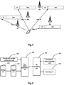
- FIG.1 a system for uplink synchronization is proposed as shown in FIG.1 , which includes the following base stations and User Equipment (UE).
- UE User Equipment
- a base station as shown in FIG.2 which includes a trigger unit 210 configured to instruct a UE to perform a dedicated Physical Random Access Channel (PRACH) transmission; a base station transceiver unit 220 configured to send the instruction from the trigger unit to the UE; a propagation delay estimating unit 230 configured to estimate the propagation delay based on detection of the dedicated PRACH transmission performed by the UE, so as to derive first timing information; a timing advance (TA) calculating unit 240 configured to calculate the timing advance according to the first timing information and second timing information received by the transceiver unit 220 from a plurality of non-serving base stations(NSBS), and to send the timing advance to the UE through the base station transceiver unit 220, wherein the first timing information and the second timing information are associated with propagation delays of the dedicated PRACH transmission performed by the UE.
- PRACH Physical Random Access Channel
- the base station further includes a coordinated multiple points main unit 250 configured to receive, through the base stations transceiver unit 220, the uplink transmission directly from the UE and the uplink transmissions forwarded by the plurality of non-serving base stations and performed by the UE according to the established uplink synchronization, and to combine the uplink transmission directly from the UE and the uplink transmissions forwarded the plurality of non-serving base stations so as to perform CoMP transmission.
- a coordinated multiple points main unit 250 configured to receive, through the base stations transceiver unit 220, the uplink transmission directly from the UE and the uplink transmissions forwarded by the plurality of non-serving base stations and performed by the UE according to the established uplink synchronization, and to combine the uplink transmission directly from the UE and the uplink transmissions forwarded the plurality of non-serving base stations so as to perform CoMP transmission.
- the base station further includes a selecting unit 260 configured to, when the plurality of non-serving base stations includes a non-serving base station that makes it unable to generate the timing advance for establishing the uplink synchronization, exclude the second timing information of that non-serving base station.
- the TA calculating unit is further configured to recalculate the timing advance according to the first timing information and the second timing information provided by remaining non-serving base stations left in the plurality of non-serving base stations after the exclusion.
- the base station further includes a storage unit 270 configured to store dedicated PRACH random access codes.
- the trigger unit 210 is further configured to select an unused dedicated PRACH random access code from the storage unit 270 and send it to the UE through the base station transceiver unit 220 to request the UE to perform the dedicated PRACH transmission based on the unused dedicated PRACH random access code.
- the trigger unit 210 is further configured to notify the selected unused dedicated PRACH random access code to the plurality of non-serving base stations through the base station transceiver unit 220.
- a base station as shown in FIG.3 which includes a detecting unit 310 configured to detect a dedicated PRACH transmission from a UE; and a delay estimating unit 320 configured to estimate a propagation delay according to the dedicated PRACH transmission detected by the detecting unit 310 so as to derive timing information, and to send through the detecting unit 310 the timing information to a serving base station of the UE to calculate the timing advance.
- the detecting unit 310 is further configured to receive information of a first dedicated random access code from the serving base station. If the detected dedicated PRACH transmission includes a second dedicated random access code identical to the first dedicated random access code, the delay estimating unit 320 is further configured to estimate the propagation delay of the detected dedicated PRACH transmission so as to derive the timing information.
- the detecting unit 310 is further configured to detect the uplink transmission performed by the UE after the uplink synchronization is established according the timing advance, and to forward the detected uplink transmission to the serving base station of the UE to perform CoMP transmission.
- a User Equipment as shown in FIG.4 is proposed, which includes a UE transceiver unit 410 configured to receive a dedicated PRACH transmission instruction and a TA from the UE's serving base station, wherein the TA is a timing advance calculated by the UE's serving base station according to both the timing information of the propagation delay of the dedicated PRACH transmission performed by the UE derived by the UE's serving base station itself and the timing information of the propagation delays of the dedicated PRACH transmission performed by the UE received from the other base stations; a PRACH transmitting unit 420 configured to perform the dedicated PRACH transmission according the received dedicated PRACH transmission instruction; and a UL transmitting unit 430 configured to perform UL transmission according to the received TA.
- a UE transceiver unit 410 configured to receive a dedicated PRACH transmission instruction and a TA from the UE's serving base station, wherein the TA is a timing advance calculated by the UE's serving base station according to both the timing information of the propagation delay of the dedicated PR
- base station and UE in embodiments of the invention are described by means of separate functional modules, in actual applications respective component shown in FIGs.2-4 may be implemented by a plurality of devices and in actual applications a plurality of components shown in the accompanying figures may be integrated into a single chip or a single equipment.
- the base station and the UE may further include any other units and means for other purposes.
- FIG.5 For a UL CoMP scenario, an embodiment of the invention employs a contention-free PRACH transmission strategy. The specific steps are shown in FIG.5 .
- step S510 the trigger unit 210 of a Serving Base Station (SBS) selects an unused dedicated random access code from its dedicated RACH preamble pool and notifies it to all involved non-serving base stations through the base station transceiver unit 220.
- the serving base station also requests the UE to perform a dedicated PRACH transmission based the selected dedicated random synchronization code.
- step S520 the PRACH transmitting unit 420 of the UE performs the dedicated PRACH transmission accordingly.
- step S530 the detecting unit 310 of a non-serving base station detects the dedicated PRACH transmission, and the delay estimating unit 320 estimates a propagation delay according to the detected dedicated PRACH transmission.
- the propagation delay estimating unit 230 of the serving base station estimates a propagation delay according to the dedicated PRACH transmission detected by the base station transceiver unit 220.
- step S540 the TA calculating unit 240 of the serving base station determines a new TA command according to timing information it received (i.e. second timing information) and timing information estimated by its propagation delay estimating unit 230 (i.e. first timing information) so as to guarantee that the timings within which the UL transmission arrives at the involved base stations are covered by the base station's CP. Then the serving base station delivers a TA command to the UE through the base station transceiver unit 220.
- timing information it received i.e. second timing information
- timing information estimated by its propagation delay estimating unit 230 i.e. first timing information
- step S550 the UL transmitting unit 430 of the UE uses the TA command received by the UE transceiver unit to perform the UL synchronization of all involved base stations.
- the UE may initiate a UL transmission.
- the UL transmission is forwarded to a serving base station if the detecting unit 310 of a non-serving base station detects it.
- the serving base station receives the UL transmission from the UE and the UL transmissions forwarded by the non-serving base stations through the base station transceiver unit 220 and combines them by the coordinated multiple points unit 250.
- the solution provided by embodiments of the invention may also be used to determine whether a UE is able to employ the UL CoMP technology. For example, if the serving station may not find a TA command that may guarantee UL transmissions to arrive at the base station within the shortest/longest propagation delay of the CP's coverage, the UE may not employ UL CoMP since there are base stations that cannot receive the UE's UL transmission. Otherwise, from another point of view, the solution may choose an appropriate base station to provide service for the UE. For example, the selecting unit 260 of the serving base station may select the base stations whose CP may cover the UE's UL transmission and put into the UE's UL CoMP set.
- the baseline is that the UE establishes the UL synchronization to all involved base stations.
- the all involved base stations measure their propagation delays to the UE and exchange information of the propagation delays to generate a predefined timing advance command so that UL transmissions of the UE are all covered by their CP, as shown in FIG.1 .
- t4 is the shortest propagation delay while t3 is the longest one.
- a TA command may be determined to guarantee the UL transmission arrivals at BS4 and BS3 in CP's coverage.
- the UL transmission arrives at BS4 at the beginning of the CP and arrives at BS3 at the end of the CP. It is apparent that the UL transmission will also arrives at BS1 and BS2 in the CP's coverage. Therefore, the UL synchronization between UE and all involved BSs is established.
- some embodiments may involve machine readable or computer readable program storage devices, e.g., digital data storage media, and encoded program instructions executable by machine or computer, wherein said instructions perform some or all of the steps of the above methods.
- the program storage devices may be, for example, digital memories, magnetic storage media such as magnetic disks and magnetic tapes, hard drives, or optically readable digital data storage media.
- the embodiments also intends to cover computers programmed to perform steps of the above methods.
Description
- The present invention relates to wireless communication technology, and more particularly to a method and device for implementing uplink synchronization.
- Uplink (UL) Coordinated Multiple Points (CoMP) has been accepted in 36.814 as an important candidate for enhancing UL capacity in an LTE-advanced system. For UL CoMP, more than one base stations (BSs) are configured to receive the UL transmission from a UE and the received signals are combined to get combining gain. The most important baseline for implementation of UL CoMP is that all involved base stations must be able to receive the UL transmissions from a UE, that is, the UE should perform UL synchronization with all involved base stations prior to the UL transmission so as to solve the different propagation delays between UE and involved base stations. For example, as shown in
FIG. 6 , this issue due to the difference between the propagation delays t1 and t2 for the involved base stations BS1 and BS2 must be resolved if UL CoMP is to be performed. - In general speaking, UL synchronization means that UE's transmission arrives at involved base stations within their Cyclic Prefix (CP)'s coverage; otherwise, if the UL transmission arrives at a base station before or late to its CP's coverage, the impacted base station may not decode this UL transmission correctly, hence the UL CoMP may not be achieved. In this case a feasible solution is provided to solve this problem. To guarantee UE's UL transmission arriving at the base station during its CP's coverage, a straightforward way is to design a longer CP to eliminate the impact of different propagation delays. As shown in
figure 7 , infigure 7 , it is clear that the UL transmission to both BS1 and BS2 are in the CP's coverage. However, this solution has the following drawbacks: - 1. It is very hard to determine an optimal CP length to cover different UL CoMP scenarios. For example, for scenarios where propagation delays to the involved base stations are similar, a small CP length is enough, however, it is not applicable to scenarios where the propagation delays varied dramatically. Also the longer CP will result in resource waste for scenarios with similar propagation delays.
- 2. This longer CP results in large overhead and leads to UL capacity loss. The reason is that the symbols which should be used to send data are now occupied by extended CP.
- 3. This solution may not support legacy UEs.
- 4. Scheduling flexibility is restricted since the UL CoMP may only be scheduled in the frame with longer CP length.
- A document
CN 1 452 821 A provides a method for fastly synchronizing uplink in a synchronization code division multiple access (SCDMA) communication system. - Another document "HUAWEI: 'System performance evaluation for uplink CoMP', 3GPP DRAFT; R1-091618, 3RD GENERATION PARTNERSHIP PROJECT (3GPP), MOBILE COMPETENCE CENTRE ; 650, ROUTE DES LUCIOLES ; F-06921 SOPHIA-ANTIPOLIS CEDEX ; FRANCE, no. Seoul, Korea; 20090328, 28 March 2009 (2009-03-28), XP050339161, [retrieved on 2009-03-28]", regards a system performance evaluation for uplink CoMP in an FDD system.
- Another document
WO 2008/084967 A1 discloses a method for measuring a position including a step of allocating a first ranging code and a first ranging region for a mobile station, and including a step of receiving a second ranging code and allocation information on a second ranging region of the mobile station from a neighboring base station. - Embodiments of the present invention propose a method and system for establishing UL synchronization in order to solve the above issues.
- According to an aspect of the present invention, a method for establishing uplink synchronization is provided. The method includes: instructing a UE to perform a dedicated PRACH transmission; and calculating a timing advance (TA) according to first timing information derived by itself and second timing information received from a plurality of non-serving base stations, and sending the timing advance to the UE to enable the UE to establish the uplink synchronization with involved base stations according to the timing advance, wherein the first timing information and the second timing information are associated with propagation delays of the dedicated PRACH transmission performed by the UE.
- According to another aspect of the present invention, it is provided a base station including: a trigger unit configured to instruct a UE to perform a dedicated PRACH transmission; a base stations transceiver unit configured to send the instruction from the trigger unit to the UE; a propagation delay estimating unit configured to estimate a propagation delay based on detection of the dedicated PRACH transmission performed by the UE, so as to derive first timing information; and a TA calculating unit configured to calculate the timing advance (TA) according to the first timing information and second timing information received by the transceiver unit (220) from a plurality of non-serving base stations, and to send the timing advance to the UE through the base station transceiver unit, wherein the first timing information and the second timing information are associated with propagation delays of the dedicated PRACH transmission performed by the UE.
- According to another aspect of the present invention, it is provided a base station including: a detecting unit configured to detect a dedicated PRACH transmission from a UE; and a delay estimating unit configured to estimate a propagation delay according to the dedicated PRACH transmission detected by the detecting unit so as to derive timing information, and to send through the detecting unit the timing information to a serving base station of the UE to calculate a timing advance.
- According to another aspect of the present invention, it is provided a User Equipment (UE) including: a UE transceiver unit configured to receive a dedicated PRACH transmission instruction and a TA from the UE's serving base stations, wherein the TA is a timing advance calculated by the UE's serving base station according to both timing information of a propagation delay of the dedicated PRACH transmission performed by the UE derived by the UE's serving base station itself and timing information of propagation delays of the dedicated PRACH transmission performed by the UE received from the other base stations; a PRACH transmitting unit configured to perform the dedicated PRACH transmission according the received dedicated PRACH transmission instruction; and a UL transmitting unit configured to perform uplink transmission according to the received TA.
- According to another aspect of the present invention, it is provided a communication system comprising the above base stations and user equipment.
- Based on the above solution, it's advantage lines in that it's easy to establish a synchronization between the UE and all involved base stations for the UL CoMP; backward compatibility is supported without making any modification to the UE's software, hardware or protocol; and there is no impact on capacity and scheduling flexibility since it does not need to extend CP.
- The advantages of the present invention will become more apparent from following detailed description in conjunction with the accompanying drawings, wherein:
-
FIG. 1 illustrates a schematic drawing of a system for UL CoMP according to an embodiment of the present invention; -
FIG. 2 illustrates a block diagram of a serving base station for UL CoMP according to an embodiment of the present invention; -
FIG. 3 illustrates a block diagram of a non-serving base station for UL CoMP according to an embodiment of the present invention; -
FIG. 4 illustrates a block diagram of a UE for UL CoMP according to an embodiment of the present invention; -
FIG. 5 illustrates a flow diagram of a method for UL CoMP according to an embodiment of the present invention; -
FIG. 6 illustrates a schematic drawing of propagation delays between a UE and different base stations; -
FIG. 7 illustrates a schematic drawing of a scheme to deal with different propagation delays in the prior art. - Preferred embodiments of the present invention will now be explained in detail with reference to the accompanying drawings. Details and functions that are not necessary for the present invention are omitted in the description so as not to obscure the understanding of the present invention.
- In an embodiment of the present invention, a system for uplink synchronization is proposed as shown in
FIG.1 , which includes the following base stations and User Equipment (UE). - Also, a base station as shown in
FIG.2 is proposed, which includes atrigger unit 210 configured to instruct a UE to perform a dedicated Physical Random Access Channel (PRACH) transmission; a basestation transceiver unit 220 configured to send the instruction from the trigger unit to the UE; a propagationdelay estimating unit 230 configured to estimate the propagation delay based on detection of the dedicated PRACH transmission performed by the UE, so as to derive first timing information; a timing advance (TA) calculatingunit 240 configured to calculate the timing advance according to the first timing information and second timing information received by thetransceiver unit 220 from a plurality of non-serving base stations(NSBS), and to send the timing advance to the UE through the basestation transceiver unit 220, wherein the first timing information and the second timing information are associated with propagation delays of the dedicated PRACH transmission performed by the UE. - The base station further includes a coordinated multiple points
main unit 250 configured to receive, through the basestations transceiver unit 220, the uplink transmission directly from the UE and the uplink transmissions forwarded by the plurality of non-serving base stations and performed by the UE according to the established uplink synchronization, and to combine the uplink transmission directly from the UE and the uplink transmissions forwarded the plurality of non-serving base stations so as to perform CoMP transmission. - The base station further includes a selecting
unit 260 configured to, when the plurality of non-serving base stations includes a non-serving base station that makes it unable to generate the timing advance for establishing the uplink synchronization, exclude the second timing information of that non-serving base station. The TA calculating unit is further configured to recalculate the timing advance according to the first timing information and the second timing information provided by remaining non-serving base stations left in the plurality of non-serving base stations after the exclusion. - The base station further includes a
storage unit 270 configured to store dedicated PRACH random access codes. Thetrigger unit 210 is further configured to select an unused dedicated PRACH random access code from thestorage unit 270 and send it to the UE through the basestation transceiver unit 220 to request the UE to perform the dedicated PRACH transmission based on the unused dedicated PRACH random access code. Thetrigger unit 210 is further configured to notify the selected unused dedicated PRACH random access code to the plurality of non-serving base stations through the basestation transceiver unit 220. - Also, a base station as shown in
FIG.3 is proposed, which includes a detectingunit 310 configured to detect a dedicated PRACH transmission from a UE; and adelay estimating unit 320 configured to estimate a propagation delay according to the dedicated PRACH transmission detected by the detectingunit 310 so as to derive timing information, and to send through the detectingunit 310 the timing information to a serving base station of the UE to calculate the timing advance. - Furthermore, the detecting
unit 310 is further configured to receive information of a first dedicated random access code from the serving base station. If the detected dedicated PRACH transmission includes a second dedicated random access code identical to the first dedicated random access code, thedelay estimating unit 320 is further configured to estimate the propagation delay of the detected dedicated PRACH transmission so as to derive the timing information. - The detecting
unit 310 is further configured to detect the uplink transmission performed by the UE after the uplink synchronization is established according the timing advance, and to forward the detected uplink transmission to the serving base station of the UE to perform CoMP transmission. - Also, a User Equipment (UE) as shown in
FIG.4 is proposed, which includes a UEtransceiver unit 410 configured to receive a dedicated PRACH transmission instruction and a TA from the UE's serving base station, wherein the TA is a timing advance calculated by the UE's serving base station according to both the timing information of the propagation delay of the dedicated PRACH transmission performed by the UE derived by the UE's serving base station itself and the timing information of the propagation delays of the dedicated PRACH transmission performed by the UE received from the other base stations; a PRACH transmittingunit 420 configured to perform the dedicated PRACH transmission according the received dedicated PRACH transmission instruction; and a UL transmittingunit 430 configured to perform UL transmission according to the received TA. - Although the base station and UE in embodiments of the invention are described by means of separate functional modules, in actual applications respective component shown in
FIGs.2-4 may be implemented by a plurality of devices and in actual applications a plurality of components shown in the accompanying figures may be integrated into a single chip or a single equipment. The base station and the UE may further include any other units and means for other purposes. - The specific structures and operation processes of the above described base station and user equipment (UE, for example) will now be described in detail in conjunction with
FIG.5 . For a UL CoMP scenario, an embodiment of the invention employs a contention-free PRACH transmission strategy. The specific steps are shown inFIG.5 . - In step S510, the
trigger unit 210 of a Serving Base Station (SBS) selects an unused dedicated random access code from its dedicated RACH preamble pool and notifies it to all involved non-serving base stations through the basestation transceiver unit 220. The serving base station also requests the UE to perform a dedicated PRACH transmission based the selected dedicated random synchronization code. - In step S520, the
PRACH transmitting unit 420 of the UE performs the dedicated PRACH transmission accordingly. - In step S530, the detecting
unit 310 of a non-serving base station detects the dedicated PRACH transmission, and thedelay estimating unit 320 estimates a propagation delay according to the detected dedicated PRACH transmission. At the same time, the propagationdelay estimating unit 230 of the serving base station estimates a propagation delay according to the dedicated PRACH transmission detected by the basestation transceiver unit 220. When the dedicated PRACH random access code received from the UE by the non-serving base station is identical to that received from the serving base station, the non-serving base station reports the estimated timing information of the propagation delay through the transmittingunit 420. - In step S540, the
TA calculating unit 240 of the serving base station determines a new TA command according to timing information it received (i.e. second timing information) and timing information estimated by its propagation delay estimating unit 230 (i.e. first timing information) so as to guarantee that the timings within which the UL transmission arrives at the involved base stations are covered by the base station's CP. Then the serving base station delivers a TA command to the UE through the basestation transceiver unit 220. - In step S550, the
UL transmitting unit 430 of the UE uses the TA command received by the UE transceiver unit to perform the UL synchronization of all involved base stations. - After the UL synchronization is established, the UE may initiate a UL transmission. The UL transmission is forwarded to a serving base station if the detecting
unit 310 of a non-serving base station detects it. The serving base station receives the UL transmission from the UE and the UL transmissions forwarded by the non-serving base stations through the basestation transceiver unit 220 and combines them by the coordinatedmultiple points unit 250. - The solution provided by embodiments of the invention may also be used to determine whether a UE is able to employ the UL CoMP technology. For example, if the serving station may not find a TA command that may guarantee UL transmissions to arrive at the base station within the shortest/longest propagation delay of the CP's coverage, the UE may not employ UL CoMP since there are base stations that cannot receive the UE's UL transmission. Otherwise, from another point of view, the solution may choose an appropriate base station to provide service for the UE. For example, the selecting
unit 260 of the serving base station may select the base stations whose CP may cover the UE's UL transmission and put into the UE's UL CoMP set. - With respect to the UL CoMP implementation in embodiments of the invention, the baseline is that the UE establishes the UL synchronization to all involved base stations. The all involved base stations measure their propagation delays to the UE and exchange information of the propagation delays to generate a predefined timing advance command so that UL transmissions of the UE are all covered by their CP, as shown in
FIG.1 . InFIG.1 , it's assumed that t4 is the shortest propagation delay while t3 is the longest one. Then a TA command may be determined to guarantee the UL transmission arrivals at BS4 and BS3 in CP's coverage. For example, the UL transmission arrives at BS4 at the beginning of the CP and arrives at BS3 at the end of the CP. It is apparent that the UL transmission will also arrives at BS1 and BS2 in the CP's coverage. Therefore, the UL synchronization between UE and all involved BSs is established. - In the above described solution, from UE's point of view, what the UE needs to do is to perform the dedicated PRACH transmission and adopt a new TA command to perform the UL transmission when it receives the new TA command. Compared with general UE operation in LTE, it does not need any modification to the protocols or softwares. From this point, backward compatibility is supported by the solution proposed by the invention. Furthermore, since normal CP length is adopted, it does not result in any additional overhead or any impact on UL capacity.
- Those skilled in the art would readily appreciate that various steps of the above methods may be performed by programmed computers. Herein, some embodiments may involve machine readable or computer readable program storage devices, e.g., digital data storage media, and encoded program instructions executable by machine or computer, wherein said instructions perform some or all of the steps of the above methods. The program storage devices may be, for example, digital memories, magnetic storage media such as magnetic disks and magnetic tapes, hard drives, or optically readable digital data storage media. The embodiments also intends to cover computers programmed to perform steps of the above methods.
- The description and drawings merely illustrate the principles of the invention. Furthermore, all examples recited herein are principally intended expressly to be only for teaching purposes to help the readers understanding the principles of the invention and the concepts contributed by the inventors to furthering the art, and are to be construed as being not limitations to such specifically recited examples and conditions. Moreover, all statements herein reciting principles, aspects, and embodiments of the invention, as well as specific examples thereof, are intended to encompass equivalents thereof.
- The above description only serves as embodiments for implementing the invention, which is defined by the appended claims.
Claims (13)
- A method to be performed at a serving base station for establishing uplink synchronization comprising the steps of:instructing a User Equipment, UE, to perform a dedicated Physical Random Access Channel, PRACH, transmission; andcalculating a timing advance, TA, according to first timing information derived by itself and second timing information received from a plurality of non-serving base stations, andsending the timing advance to the UE to enable the UE to establish the uplink synchronization with involved base stations according to the timing advance, wherein the first timing information and the second timing information are associated with propagation delays of the dedicated PRACH transmission performed by the UE.
- The method of claim 1, further comprising: receiving uplink transmissions received by the plurality of non-serving base stations and performed by the UE according to the established uplink synchronization; and combining the received uplink transmissions and the UE's uplink transmission received by itself to perform Coordinated Multiple Points, CoMP, transmission.
- The method of claim 1, wherein instructing the UE to perform the dedicated PRACH transmission comprises: selecting an unused dedicated PRACH random access code from its dedicated RACH preamble pool and sending it to the UE to request the UE to perform the dedicated PRACH transmission based the unused dedicated PRACH random access code; and notifying the selected unused dedicated PRACH random access code to the plurality of non-serving base stations.
- The method of claim 3, wherein calculating the timing advance, TA, according to the first timing information derived by itself and the second timing information received from the plurality of non-serving base stations comprises: estimating the propagation delay based on detection of the dedicated PRACH transmission performed by the UE so as to derive the first timing information; and calculating the timing advance according to the estimated first timing information and the second timing information received from the plurality of non-serving base stations, wherein the second timing information is reported by the plurality of non-serving base stations to a serving station when the dedicated PRACH random access code received by the plurality of non-serving base stations from the UE is identical to the dedicated PRACH random access code received from the serving station.
- The method of claim 1, wherein when the plurality of non-serving base stations include a non-serving base station that makes it unable to generate the timing advance for establishing the uplink synchronization, the second timing information provided by that non-serving base station is excluded; and the timing advance is recalculated according to the first timing information and the second timing information provided by remaining non-serving base stations left in the plurality of non-serving base stations after the exclusion.
- A serving base station comprising: a trigger unit (210) configured to instruct a User Equipment, UE, to perform a dedicated Physical Random Access Channel, PRACH, transmission; a base stations transceiver unit (220) configured to send the instruction from the trigger unit (210) to the UE; a propagation delay estimating unit (230) configured to estimate a propagation delay based on detection of the dedicated PRACH transmission performed by the UE, so as to derive a first timing information; and a timing advance, TA, calculating unit (240) configured to calculate the timing advance, TA, according to the first timing information and a second timing information received by the transceiver unit (220) from a plurality of non-serving base stations, and to send the timing advance to the UE through the base station transceiver unit (220), wherein the first timing information and the second timing information are associated with propagation delays of the dedicated PRACH transmission performed by the UE.
- The base station of claim 6, further comprising a storage unit (270) configured to store dedicated PRACH random access codes; and wherein the trigger unit (210) is further configured to select an unused dedicated PRACH random access code from the storage unit (270) and send it to the UE through the base station transceiver unit (220) to request the UE to perform the dedicated PRACH transmission based on the unused dedicated PRACH random access code, and the trigger unit (210) is further configured to notify the selected unused dedicated PRACH random access code to the plurality of non-serving base stations through the base station transceiver unit (220).
- The base station of claim 6, further comprising a coordinated multiple points unit (250) configured to receive through the base stations transceiver unit (220) uplink transmission directly from the UE and uplink transmissions forwarded by the plurality of non-serving base stations and performed by the UE according to the established uplink synchronization, and to combine the uplink transmission directly from the UE and the uplink transmissions forwarded by the plurality of non-serving base stations so as to perform Coordinated Multiple Points (CoMP) transmission.
- The base station of claim 6, further comprising a selecting unit (260) configured to, when the plurality of non-serving base stations includes a non-serving base station that makes it unable to generate the timing advance for establishing the uplink synchronization, exclude the second timing information of that non-serving base station; and wherein the TA calculating unit (240) is further configured to recalculate the timing advance according to the first timing information and the second timing information provided by remaining non-serving base stations left in the plurality of non-serving base stations after the exclusion.
- A non-serving base station comprising: a detecting unit (310) configured to detect a dedicated Physical Random Access Channel, PRACH, transmission from a User Equipment (UE); and
a delay estimating unit (320) configured to estimate a propagation delay according to the dedicated PRACH transmission detected by the detecting unit (310) so as to derive timing information, and to send through the detecting unit (310) the timing information to a serving base station of the UE to calculate a timing advance
wherein the detecting unit (310) is further configured to receive information of a first dedicated random access code from the serving base station, and the delay estimating unit (320) is further configured to estimate the propagation delay of the detected dedicated PRACH transmission so as to derive the timing information if the detected dedicated PRACH transmission includes a second dedicated random access code identical to the first dedicated random access code. - The base station of claim 10, wherein the detecting unit (310) is further configured to detect an uplink transmission performed by the UE after the uplink synchronization is established according the timing advance, and to forward the detected uplink transmission to the serving base station of the UE to perform Coordinated Multiple Points, CoMP, transmission.
- A User Equipment, UE, comprising: a UE transceiver unit (410) configured to receive a dedicated Physical Random Access Channel, PRACH, transmission instruction and a timing advance, TA, from the UE's serving base stations, wherein the TA is a timing advance calculated by the UE's serving base station according to both timing information of a propagation delay of the dedicated PRACH transmission performed by the UE derived by the UE's serving base station itself and timing information of propagation delays of the dedicated PRACH transmission performed by the UE received from the other base stations; a PRACH transmitting unit (420) configured to perform the dedicated PRACH transmission according the received dedicated PRACH transmission instruction; and an uplink (UL) transmitting unit (430) configured to perform uplink transmission according to the received TA.
- A communication system comprising the base station of any one of claims 6-9, the base station of any one of claims 10-11 and the user equipment of claim 12.
Applications Claiming Priority (1)
| Application Number | Priority Date | Filing Date | Title |
|---|---|---|---|
| PCT/CN2009/000687 WO2010148532A1 (en) | 2009-06-22 | 2009-06-22 | Method and device for establishing uplink synchronization |
Publications (3)
| Publication Number | Publication Date |
|---|---|
| EP2448340A1 EP2448340A1 (en) | 2012-05-02 |
| EP2448340A4 EP2448340A4 (en) | 2015-02-11 |
| EP2448340B1 true EP2448340B1 (en) | 2018-09-05 |
Family
ID=43385846
Family Applications (1)
| Application Number | Title | Priority Date | Filing Date |
|---|---|---|---|
| EP09846332.6A Not-in-force EP2448340B1 (en) | 2009-06-22 | 2009-06-22 | Method and device for establishing uplink synchronization |
Country Status (7)
| Country | Link |
|---|---|
| US (1) | US8682369B2 (en) |
| EP (1) | EP2448340B1 (en) |
| JP (1) | JP5748749B2 (en) |
| KR (1) | KR20130085357A (en) |
| CN (1) | CN102396274B (en) |
| BR (1) | BRPI0925300B1 (en) |
| WO (1) | WO2010148532A1 (en) |
Families Citing this family (31)
| Publication number | Priority date | Publication date | Assignee | Title |
|---|---|---|---|---|
| TWI487416B (en) | 2008-12-03 | 2015-06-01 | Interdigital Patent Holdings | Uplink power headroom reporting for carrier aggregation |
| RU2565030C2 (en) | 2009-02-09 | 2015-10-10 | Интердиджитал Пэйтент Холдингз, Инк. | Device and method of controlling uplink power for wireless transmit/receive unit using multiple carriers |
| KR101811114B1 (en) | 2009-10-01 | 2017-12-20 | 인터디지탈 패튼 홀딩스, 인크 | Power control methods and apparatus |
| EP2536232A4 (en) * | 2010-02-12 | 2016-11-23 | Mitsubishi Electric Corp | Mobile communication system |
| US20110319066A1 (en) * | 2010-06-24 | 2011-12-29 | Industrial Technology Research Institute | Apparatus and method for relaying content between a macrocell and a femtocell |
| CN102647780A (en) * | 2011-02-17 | 2012-08-22 | 中兴通讯股份有限公司 | Long term evolution (LTE) time adjustment method and base station |
| GB2493707A (en) * | 2011-08-12 | 2013-02-20 | Sharp Kk | Using common time alignment timer for time advance values from multiple base stations with similar rates of change |
| CN103001678B (en) * | 2011-09-10 | 2016-05-25 | 华为技术有限公司 | The method and apparatus of multi-node collaboration transmission |
| BR112014007765B1 (en) * | 2011-09-30 | 2022-03-22 | Interdigital Patent Holdings, Inc | Wireless transmit/receive unit for multi-point transmission in wireless communication |
| JP5902817B2 (en) * | 2011-09-30 | 2016-04-13 | 京セラ株式会社 | System and method for mitigating uplink interference of small cells |
| US9210666B2 (en) | 2011-10-03 | 2015-12-08 | Qualcomm Incorporated | Method and apparatus for uplink transmission power control and timing in coordinated multipoint transmission schemes |
| JP5997183B2 (en) * | 2012-01-19 | 2016-09-28 | 京セラ株式会社 | base station |
| US9572123B2 (en) * | 2012-03-14 | 2017-02-14 | Fujitsu Limited | Multiple time advance for radio access networks |
| CN102685874B (en) * | 2012-04-12 | 2018-11-23 | 南京中兴新软件有限责任公司 | Deviation calibration mthods, systems and devices between a kind of multiple access points |
| KR101456700B1 (en) * | 2012-09-10 | 2014-10-31 | 주식회사 케이티 | Method for estimating uplink channel and communication system |
| EP2982194A1 (en) | 2013-04-03 | 2016-02-10 | Interdigital Patent Holdings, Inc. | Method and apparatus for controlling uplink transmission power based on accumulated transmit power control commands and corresponding uplink subframe sets |
| WO2015022750A1 (en) * | 2013-08-15 | 2015-02-19 | 富士通株式会社 | Communication apparatus and communication method in radio communication system |
| CN104812054B (en) * | 2014-01-27 | 2019-09-17 | 中兴通讯股份有限公司 | A kind of delay inequality determines method, system, base station and user equipment |
| KR101706210B1 (en) | 2014-02-12 | 2017-02-15 | 한국전자통신연구원 | Base station and communication system comprising thereof, coordinated communication method of base station |
| JP6484238B2 (en) * | 2014-06-27 | 2019-03-13 | ▲ホア▼▲ウェイ▼技術有限公司Huawei Technologies Co.,Ltd. | Data signal and method for transmitting user equipment |
| KR102313835B1 (en) * | 2015-02-13 | 2021-10-18 | 삼성전자 주식회사 | Apparatus and method for measuring traffic of users in a building using distributed antenna system |
| US10034295B2 (en) | 2015-07-15 | 2018-07-24 | Nokia Solutions And Networks Oy | Coordination of downlink channel assignments for communication with cluster of access points in wireless network |
| ES2925003T3 (en) | 2015-11-18 | 2022-10-13 | Ipcom Gmbh & Co Kg | Random access to single frequency network |
| JPWO2017094299A1 (en) * | 2015-11-30 | 2018-09-13 | 株式会社Nttドコモ | Base station and timing control method |
| CN111225449A (en) * | 2015-12-18 | 2020-06-02 | 华为技术有限公司 | Wireless frame transmission method and wireless network equipment |
| WO2017132997A1 (en) | 2016-02-05 | 2017-08-10 | 广东欧珀移动通信有限公司 | Switching resource configuration method, network access point and mobile station |
| WO2017194121A1 (en) * | 2016-05-12 | 2017-11-16 | Nokia Solutions And Networks Oy | Techniques to support ultra-reliable handover in wireless networks |
| US11533762B2 (en) | 2018-07-04 | 2022-12-20 | Lg Electronics Inc. | Method for performing uplink transmission in wireless communication system, and apparatus therefor |
| CN112449416A (en) * | 2019-08-30 | 2021-03-05 | 成都华为技术有限公司 | Data transmission method and device |
| GB2599953A (en) * | 2020-10-16 | 2022-04-20 | Canon Kk | Method and apparatus for synchronising apparatuses of a wireless network |
| US11696221B2 (en) * | 2021-02-04 | 2023-07-04 | Cisco Technology, Inc. | Adaptive beacon report for client devices |
Family Cites Families (9)
| Publication number | Priority date | Publication date | Assignee | Title |
|---|---|---|---|---|
| DE10008653A1 (en) * | 2000-02-24 | 2001-09-06 | Siemens Ag | Improvements in a radio communication system |
| WO2003007520A1 (en) * | 2001-07-13 | 2003-01-23 | Linkair Communications, Inc. | A method and system for fast synchronization of uplink and a receiver for base station's access channel |
| TW200729990A (en) * | 2005-12-22 | 2007-08-01 | Interdigital Tech Corp | Method and system for adjusting uplink transmission timing immediately for long term evolution handover |
| CN101416556B (en) * | 2006-04-07 | 2011-04-06 | 艾利森电话股份有限公司 | Method, user equipment and radio base station for random access in honeycomb telecommunication system |
| CN101064561B (en) | 2006-04-29 | 2011-08-10 | 华为技术有限公司 | Method for realizing uplink synchronization during inter-cell switch process |
| US7570962B2 (en) * | 2006-07-12 | 2009-08-04 | Intel Corporation | Wireless access network base station and method for determining location information for a mobile station using uplink time-difference of arrival |
| WO2008084967A1 (en) * | 2007-01-08 | 2008-07-17 | Electronics And Telecommunications Research Institute | Method for location determinating |
| DE602008054404C5 (en) * | 2007-06-12 | 2024-04-11 | MiiCs & Partners Japan Co., Ltd. | Base station, mobile station, and method for requesting uplink synchronization. |
| US20090290555A1 (en) * | 2008-05-21 | 2009-11-26 | Comsys Communication & Signal Processing Ltd. | Autonomous anonymous association between a mobile station and multiple network elements in a wireless communication system |
-
2009
- 2009-06-22 WO PCT/CN2009/000687 patent/WO2010148532A1/en active Application Filing
- 2009-06-22 KR KR1020127001407A patent/KR20130085357A/en not_active Application Discontinuation
- 2009-06-22 JP JP2012516465A patent/JP5748749B2/en not_active Expired - Fee Related
- 2009-06-22 US US13/379,800 patent/US8682369B2/en active Active
- 2009-06-22 CN CN200980158703.4A patent/CN102396274B/en active Active
- 2009-06-22 EP EP09846332.6A patent/EP2448340B1/en not_active Not-in-force
- 2009-06-22 BR BRPI0925300-9A patent/BRPI0925300B1/en not_active IP Right Cessation
Non-Patent Citations (1)
| Title |
|---|
| None * |
Also Published As
| Publication number | Publication date |
|---|---|
| EP2448340A4 (en) | 2015-02-11 |
| KR20130085357A (en) | 2013-07-29 |
| JP2012531128A (en) | 2012-12-06 |
| EP2448340A1 (en) | 2012-05-02 |
| US8682369B2 (en) | 2014-03-25 |
| CN102396274B (en) | 2014-04-02 |
| JP5748749B2 (en) | 2015-07-15 |
| US20120149428A1 (en) | 2012-06-14 |
| CN102396274A (en) | 2012-03-28 |
| WO2010148532A1 (en) | 2010-12-29 |
| BRPI0925300B1 (en) | 2021-01-12 |
Similar Documents
| Publication | Publication Date | Title |
|---|---|---|
| EP2448340B1 (en) | Method and device for establishing uplink synchronization | |
| CN109997405B (en) | Method for performing random access channel procedure and user equipment thereof | |
| EP2695429B1 (en) | Handover in carrier aggregation scenarios | |
| CN107534864B (en) | LBT techniques for frequency reuse in communication systems using unlicensed bands | |
| JP6195629B2 (en) | Base station, user apparatus and method for random access | |
| KR101878152B1 (en) | Wireless feedback communications over unlicensed spectrum | |
| CN103597757B (en) | For the method and apparatus of carrier activation in carrier aggregation system | |
| TWI811410B (en) | Terminal device, base station device, wireless communication method and computer program | |
| KR101783278B1 (en) | Data transmission method, device and system | |
| US10834601B2 (en) | Signal transmission method, terminal device, access network device, and transmission system for signal transmission on an unlicensed spectrum resource | |
| EP2844018A1 (en) | Method and apparatus for discovering wireless network | |
| JP6593450B2 (en) | Terminal apparatus, base station apparatus, radio communication system, and radio communication method | |
| CN105681006B (en) | A kind of method and apparatus of LAA communication | |
| JP6785220B2 (en) | User equipment and base station | |
| CN101998553A (en) | Uplink resource allocating method and equipment | |
| KR101721291B1 (en) | Method and device of transmitting data in network linked heterogeneous systems | |
| KR20170028956A (en) | Method and apparatus for performing transmission | |
| EP3101987B1 (en) | User device, base station, and control information detection method | |
| KR20160013105A (en) | Communication method and user equipment in mixed cellular and d2d network | |
| EP3542486B1 (en) | Listen before talk for reference signals in mimo systems | |
| CN112514512A (en) | User device and transmission method | |
| KR20190033575A (en) | Information transmission method and related apparatus | |
| WO2018184789A1 (en) | Data transmission in geran multilateration positioning procedure | |
| JP6950724B2 (en) | Terminal equipment, base station equipment, wireless communication systems and wireless communication methods | |
| EP3513612B1 (en) | Methods and arrangements for supporting a random access procedure |
Legal Events
| Date | Code | Title | Description |
|---|---|---|---|
| PUAI | Public reference made under article 153(3) epc to a published international application that has entered the european phase |
Free format text: ORIGINAL CODE: 0009012 |
|
| 17P | Request for examination filed |
Effective date: 20120123 |
|
| AK | Designated contracting states |
Kind code of ref document: A1 Designated state(s): AT BE BG CH CY CZ DE DK EE ES FI FR GB GR HR HU IE IS IT LI LT LU LV MC MK MT NL NO PL PT RO SE SI SK TR |
|
| DAX | Request for extension of the european patent (deleted) | ||
| 111Z | Information provided on other rights and legal means of execution |
Free format text: AT BE BG CH CY CZ DE DK EE ES FI FR GB GR HR HU IE IS IT LI LT LU LV MC MK MT NL NO PL PT RO SE SI SK TR Effective date: 20130410 |
|
| RAP1 | Party data changed (applicant data changed or rights of an application transferred) |
Owner name: ALCATEL LUCENT |
|
| D11X | Information provided on other rights and legal means of execution (deleted) | ||
| A4 | Supplementary search report drawn up and despatched |
Effective date: 20150112 |
|
| RIC1 | Information provided on ipc code assigned before grant |
Ipc: H04W 56/00 20090101AFI20150105BHEP |
|
| GRAP | Despatch of communication of intention to grant a patent |
Free format text: ORIGINAL CODE: EPIDOSNIGR1 |
|
| STAA | Information on the status of an ep patent application or granted ep patent |
Free format text: STATUS: GRANT OF PATENT IS INTENDED |
|
| RAP1 | Party data changed (applicant data changed or rights of an application transferred) |
Owner name: ALCATEL LUCENT |
|
| INTG | Intention to grant announced |
Effective date: 20180327 |
|
| GRAS | Grant fee paid |
Free format text: ORIGINAL CODE: EPIDOSNIGR3 |
|
| GRAA | (expected) grant |
Free format text: ORIGINAL CODE: 0009210 |
|
| STAA | Information on the status of an ep patent application or granted ep patent |
Free format text: STATUS: THE PATENT HAS BEEN GRANTED |
|
| AK | Designated contracting states |
Kind code of ref document: B1 Designated state(s): AT BE BG CH CY CZ DE DK EE ES FI FR GB GR HR HU IE IS IT LI LT LU LV MC MK MT NL NO PL PT RO SE SI SK TR |
|
| REG | Reference to a national code |
Ref country code: GB Ref legal event code: FG4D |
|
| REG | Reference to a national code |
Ref country code: CH Ref legal event code: EP |
|
| REG | Reference to a national code |
Ref country code: AT Ref legal event code: REF Ref document number: 1039410 Country of ref document: AT Kind code of ref document: T Effective date: 20180915 |
|
| REG | Reference to a national code |
Ref country code: IE Ref legal event code: FG4D |
|
| REG | Reference to a national code |
Ref country code: DE Ref legal event code: R096 Ref document number: 602009054397 Country of ref document: DE |
|
| REG | Reference to a national code |
Ref country code: NL Ref legal event code: MP Effective date: 20180905 |
|
| REG | Reference to a national code |
Ref country code: LT Ref legal event code: MG4D |
|
| PG25 | Lapsed in a contracting state [announced via postgrant information from national office to epo] |
Ref country code: FI Free format text: LAPSE BECAUSE OF FAILURE TO SUBMIT A TRANSLATION OF THE DESCRIPTION OR TO PAY THE FEE WITHIN THE PRESCRIBED TIME-LIMIT Effective date: 20180905 Ref country code: SE Free format text: LAPSE BECAUSE OF FAILURE TO SUBMIT A TRANSLATION OF THE DESCRIPTION OR TO PAY THE FEE WITHIN THE PRESCRIBED TIME-LIMIT Effective date: 20180905 Ref country code: BG Free format text: LAPSE BECAUSE OF FAILURE TO SUBMIT A TRANSLATION OF THE DESCRIPTION OR TO PAY THE FEE WITHIN THE PRESCRIBED TIME-LIMIT Effective date: 20181205 Ref country code: NO Free format text: LAPSE BECAUSE OF FAILURE TO SUBMIT A TRANSLATION OF THE DESCRIPTION OR TO PAY THE FEE WITHIN THE PRESCRIBED TIME-LIMIT Effective date: 20181205 Ref country code: GR Free format text: LAPSE BECAUSE OF FAILURE TO SUBMIT A TRANSLATION OF THE DESCRIPTION OR TO PAY THE FEE WITHIN THE PRESCRIBED TIME-LIMIT Effective date: 20181206 Ref country code: LT Free format text: LAPSE BECAUSE OF FAILURE TO SUBMIT A TRANSLATION OF THE DESCRIPTION OR TO PAY THE FEE WITHIN THE PRESCRIBED TIME-LIMIT Effective date: 20180905 |
|
| REG | Reference to a national code |
Ref country code: AT Ref legal event code: MK05 Ref document number: 1039410 Country of ref document: AT Kind code of ref document: T Effective date: 20180905 |
|
| PG25 | Lapsed in a contracting state [announced via postgrant information from national office to epo] |
Ref country code: HR Free format text: LAPSE BECAUSE OF FAILURE TO SUBMIT A TRANSLATION OF THE DESCRIPTION OR TO PAY THE FEE WITHIN THE PRESCRIBED TIME-LIMIT Effective date: 20180905 Ref country code: LV Free format text: LAPSE BECAUSE OF FAILURE TO SUBMIT A TRANSLATION OF THE DESCRIPTION OR TO PAY THE FEE WITHIN THE PRESCRIBED TIME-LIMIT Effective date: 20180905 |
|
| PG25 | Lapsed in a contracting state [announced via postgrant information from national office to epo] |
Ref country code: AT Free format text: LAPSE BECAUSE OF FAILURE TO SUBMIT A TRANSLATION OF THE DESCRIPTION OR TO PAY THE FEE WITHIN THE PRESCRIBED TIME-LIMIT Effective date: 20180905 Ref country code: IS Free format text: LAPSE BECAUSE OF FAILURE TO SUBMIT A TRANSLATION OF THE DESCRIPTION OR TO PAY THE FEE WITHIN THE PRESCRIBED TIME-LIMIT Effective date: 20190105 Ref country code: ES Free format text: LAPSE BECAUSE OF FAILURE TO SUBMIT A TRANSLATION OF THE DESCRIPTION OR TO PAY THE FEE WITHIN THE PRESCRIBED TIME-LIMIT Effective date: 20180905 Ref country code: EE Free format text: LAPSE BECAUSE OF FAILURE TO SUBMIT A TRANSLATION OF THE DESCRIPTION OR TO PAY THE FEE WITHIN THE PRESCRIBED TIME-LIMIT Effective date: 20180905 Ref country code: CZ Free format text: LAPSE BECAUSE OF FAILURE TO SUBMIT A TRANSLATION OF THE DESCRIPTION OR TO PAY THE FEE WITHIN THE PRESCRIBED TIME-LIMIT Effective date: 20180905 Ref country code: NL Free format text: LAPSE BECAUSE OF FAILURE TO SUBMIT A TRANSLATION OF THE DESCRIPTION OR TO PAY THE FEE WITHIN THE PRESCRIBED TIME-LIMIT Effective date: 20180905 Ref country code: RO Free format text: LAPSE BECAUSE OF FAILURE TO SUBMIT A TRANSLATION OF THE DESCRIPTION OR TO PAY THE FEE WITHIN THE PRESCRIBED TIME-LIMIT Effective date: 20180905 Ref country code: IT Free format text: LAPSE BECAUSE OF FAILURE TO SUBMIT A TRANSLATION OF THE DESCRIPTION OR TO PAY THE FEE WITHIN THE PRESCRIBED TIME-LIMIT Effective date: 20180905 Ref country code: PL Free format text: LAPSE BECAUSE OF FAILURE TO SUBMIT A TRANSLATION OF THE DESCRIPTION OR TO PAY THE FEE WITHIN THE PRESCRIBED TIME-LIMIT Effective date: 20180905 |
|
| PG25 | Lapsed in a contracting state [announced via postgrant information from national office to epo] |
Ref country code: PT Free format text: LAPSE BECAUSE OF FAILURE TO SUBMIT A TRANSLATION OF THE DESCRIPTION OR TO PAY THE FEE WITHIN THE PRESCRIBED TIME-LIMIT Effective date: 20190105 Ref country code: SK Free format text: LAPSE BECAUSE OF FAILURE TO SUBMIT A TRANSLATION OF THE DESCRIPTION OR TO PAY THE FEE WITHIN THE PRESCRIBED TIME-LIMIT Effective date: 20180905 |
|
| REG | Reference to a national code |
Ref country code: DE Ref legal event code: R097 Ref document number: 602009054397 Country of ref document: DE |
|
| PLBE | No opposition filed within time limit |
Free format text: ORIGINAL CODE: 0009261 |
|
| STAA | Information on the status of an ep patent application or granted ep patent |
Free format text: STATUS: NO OPPOSITION FILED WITHIN TIME LIMIT |
|
| PG25 | Lapsed in a contracting state [announced via postgrant information from national office to epo] |
Ref country code: DK Free format text: LAPSE BECAUSE OF FAILURE TO SUBMIT A TRANSLATION OF THE DESCRIPTION OR TO PAY THE FEE WITHIN THE PRESCRIBED TIME-LIMIT Effective date: 20180905 |
|
| 26N | No opposition filed |
Effective date: 20190606 |
|
| PG25 | Lapsed in a contracting state [announced via postgrant information from national office to epo] |
Ref country code: SI Free format text: LAPSE BECAUSE OF FAILURE TO SUBMIT A TRANSLATION OF THE DESCRIPTION OR TO PAY THE FEE WITHIN THE PRESCRIBED TIME-LIMIT Effective date: 20180905 |
|
| PG25 | Lapsed in a contracting state [announced via postgrant information from national office to epo] |
Ref country code: MC Free format text: LAPSE BECAUSE OF FAILURE TO SUBMIT A TRANSLATION OF THE DESCRIPTION OR TO PAY THE FEE WITHIN THE PRESCRIBED TIME-LIMIT Effective date: 20180905 |
|
| REG | Reference to a national code |
Ref country code: CH Ref legal event code: PL |
|
| REG | Reference to a national code |
Ref country code: BE Ref legal event code: MM Effective date: 20190630 |
|
| PG25 | Lapsed in a contracting state [announced via postgrant information from national office to epo] |
Ref country code: TR Free format text: LAPSE BECAUSE OF FAILURE TO SUBMIT A TRANSLATION OF THE DESCRIPTION OR TO PAY THE FEE WITHIN THE PRESCRIBED TIME-LIMIT Effective date: 20180905 |
|
| PG25 | Lapsed in a contracting state [announced via postgrant information from national office to epo] |
Ref country code: IE Free format text: LAPSE BECAUSE OF NON-PAYMENT OF DUE FEES Effective date: 20190622 |
|
| PG25 | Lapsed in a contracting state [announced via postgrant information from national office to epo] |
Ref country code: CH Free format text: LAPSE BECAUSE OF NON-PAYMENT OF DUE FEES Effective date: 20190630 Ref country code: LU Free format text: LAPSE BECAUSE OF NON-PAYMENT OF DUE FEES Effective date: 20190622 Ref country code: LI Free format text: LAPSE BECAUSE OF NON-PAYMENT OF DUE FEES Effective date: 20190630 Ref country code: BE Free format text: LAPSE BECAUSE OF NON-PAYMENT OF DUE FEES Effective date: 20190630 |
|
| PG25 | Lapsed in a contracting state [announced via postgrant information from national office to epo] |
Ref country code: CY Free format text: LAPSE BECAUSE OF FAILURE TO SUBMIT A TRANSLATION OF THE DESCRIPTION OR TO PAY THE FEE WITHIN THE PRESCRIBED TIME-LIMIT Effective date: 20180905 |
|
| PG25 | Lapsed in a contracting state [announced via postgrant information from national office to epo] |
Ref country code: HU Free format text: LAPSE BECAUSE OF FAILURE TO SUBMIT A TRANSLATION OF THE DESCRIPTION OR TO PAY THE FEE WITHIN THE PRESCRIBED TIME-LIMIT; INVALID AB INITIO Effective date: 20090622 Ref country code: MT Free format text: LAPSE BECAUSE OF FAILURE TO SUBMIT A TRANSLATION OF THE DESCRIPTION OR TO PAY THE FEE WITHIN THE PRESCRIBED TIME-LIMIT Effective date: 20180905 |
|
| PGFP | Annual fee paid to national office [announced via postgrant information from national office to epo] |
Ref country code: DE Payment date: 20210525 Year of fee payment: 13 Ref country code: FR Payment date: 20210513 Year of fee payment: 13 |
|
| PGFP | Annual fee paid to national office [announced via postgrant information from national office to epo] |
Ref country code: GB Payment date: 20210526 Year of fee payment: 13 |
|
| PG25 | Lapsed in a contracting state [announced via postgrant information from national office to epo] |
Ref country code: MK Free format text: LAPSE BECAUSE OF FAILURE TO SUBMIT A TRANSLATION OF THE DESCRIPTION OR TO PAY THE FEE WITHIN THE PRESCRIBED TIME-LIMIT Effective date: 20180905 |
|
| REG | Reference to a national code |
Ref country code: DE Ref legal event code: R119 Ref document number: 602009054397 Country of ref document: DE |
|
| GBPC | Gb: european patent ceased through non-payment of renewal fee |
Effective date: 20220622 |
|
| PG25 | Lapsed in a contracting state [announced via postgrant information from national office to epo] |
Ref country code: FR Free format text: LAPSE BECAUSE OF NON-PAYMENT OF DUE FEES Effective date: 20220630 |
|
| PG25 | Lapsed in a contracting state [announced via postgrant information from national office to epo] |
Ref country code: GB Free format text: LAPSE BECAUSE OF NON-PAYMENT OF DUE FEES Effective date: 20220622 Ref country code: DE Free format text: LAPSE BECAUSE OF NON-PAYMENT OF DUE FEES Effective date: 20230103 |