EP2448321A1 - Method, system and application network element for improving quality of service - Google Patents
Method, system and application network element for improving quality of service Download PDFInfo
- Publication number
- EP2448321A1 EP2448321A1 EP10791590A EP10791590A EP2448321A1 EP 2448321 A1 EP2448321 A1 EP 2448321A1 EP 10791590 A EP10791590 A EP 10791590A EP 10791590 A EP10791590 A EP 10791590A EP 2448321 A1 EP2448321 A1 EP 2448321A1
- Authority
- EP
- European Patent Office
- Prior art keywords
- resource information
- sending
- access network
- message
- enb
- Prior art date
- Legal status (The legal status is an assumption and is not a legal conclusion. Google has not performed a legal analysis and makes no representation as to the accuracy of the status listed.)
- Granted
Links
Images


Classifications
-
- H—ELECTRICITY
- H04—ELECTRIC COMMUNICATION TECHNIQUE
- H04W—WIRELESS COMMUNICATION NETWORKS
- H04W28/00—Network traffic management; Network resource management
- H04W28/16—Central resource management; Negotiation of resources or communication parameters, e.g. negotiating bandwidth or QoS [Quality of Service]
- H04W28/24—Negotiating SLA [Service Level Agreement]; Negotiating QoS [Quality of Service]
-
- H—ELECTRICITY
- H04—ELECTRIC COMMUNICATION TECHNIQUE
- H04L—TRANSMISSION OF DIGITAL INFORMATION, e.g. TELEGRAPHIC COMMUNICATION
- H04L65/00—Network arrangements, protocols or services for supporting real-time applications in data packet communication
- H04L65/10—Architectures or entities
- H04L65/1016—IP multimedia subsystem [IMS]
-
- H—ELECTRICITY
- H04—ELECTRIC COMMUNICATION TECHNIQUE
- H04L—TRANSMISSION OF DIGITAL INFORMATION, e.g. TELEGRAPHIC COMMUNICATION
- H04L65/00—Network arrangements, protocols or services for supporting real-time applications in data packet communication
- H04L65/80—Responding to QoS
-
- H—ELECTRICITY
- H04—ELECTRIC COMMUNICATION TECHNIQUE
- H04W—WIRELESS COMMUNICATION NETWORKS
- H04W28/00—Network traffic management; Network resource management
- H04W28/16—Central resource management; Negotiation of resources or communication parameters, e.g. negotiating bandwidth or QoS [Quality of Service]
- H04W28/18—Negotiating wireless communication parameters
-
- H—ELECTRICITY
- H04—ELECTRIC COMMUNICATION TECHNIQUE
- H04W—WIRELESS COMMUNICATION NETWORKS
- H04W72/00—Local resource management
- H04W72/50—Allocation or scheduling criteria for wireless resources
- H04W72/52—Allocation or scheduling criteria for wireless resources based on load
Definitions
- the present invention relates to communications technologies, and in particular, to a method, a system, and an application network element for improving Quality of Service.
- an access network is configured to transmit service data of a User Equipment (User Equipment, abbreviated as UE) and an application network is configured to control the processing of the service data, that is, to provide services to the UE.
- UE User Equipment
- steps for allocating resources to the access network include: A UE obtains an IP address by creating a default bearer and sets up a Public Data Network (Public Data Network, abbreviated as PDN) connection; the UE negotiates a resource required by a service, such as Quality of Service (Quality of Service, abbreviated as QoS), codec, etc..
- PDN Public Data Network
- QoS Quality of Service
- the application network forms a service request and sends the service request to a Policy Charging Enforcement Function (Policy Charging Enforcement Function, abbreviated as PCRF) entity, and the PCRF entity creates Policy Charging Control (Policy Charging Control, abbreviated as PCC) rules according to the service request, the PCRF entity delivers the PCC rules to a Packet Data Network Gateway (PDN Gateway, abbreviated as P-GW); the P-GW, according to the PCC rules, sets up a dedicated service bearer required by the service; and the UE exchanges service data with a remote end (such as another UE) through the set up dedicated service bearer.
- PCRF Policy Charging Enforcement Function
- PCC Policy Charging Control
- the method for setting up a service bearer in the prior art has the following problem.
- the bearer for the UE to exchange service data is set up, during the process that the UE exchanges service data, if a resource of the access network is changed, for example, the access network is congested, the previously set up service bearer does not match the changed access network resource and the previously formed service request does not match the changed access network resource either; as a result, the QoS of the service deteriorates and the service is even caused to be interrupted.
- embodiments of the present invention provide a method, a system, and an application network element for improving QoS, so that a service parameter or a service request related to a current service matches a changed access network resource, thereby improving the QoS.
- An embodiment of the present invention provides a method for improving QoS, including:
- An embodiment of the present invention provides a system for improving QoS, including:
- An embodiment of the present invention further provides an application network element, including:
- FIG. 1 is a flow chart of a method for improving QoS according to a first embodiment of the present invention
- FIG. 2 is a schematic structure diagram of an EPS involved in an embodiment of the present invention.
- FIG. 3 is a signaling interaction diagram of a method for improving QoS according to a second embodiment of the present invention.
- FIG. 4 is a signaling interaction diagram of a method for improving QoS according to a third embodiment of the present invention.
- FIG. 5 is a signaling interaction diagram of a method for improving QoS according to a fourth embodiment of the present invention.
- FIG. 6 is a signaling interaction diagram of a method for improving QoS according to a fifth embodiment of the present invention.
- FIG. 7 is a signaling interaction diagram of a method for improving QoS according to a sixth embodiment of the present invention.
- FIG. 8 is a signaling interaction diagram of a method for improving QoS according to a seventh embodiment of the present invention.
- FIG. 9 is a signaling interaction diagram of a method for improving QoS according to an eighth embodiment of the present invention.
- FIG. 10 is a signaling interaction diagram of a method for improving QoS according to a ninth embodiment of the present invention.
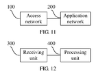
- FIG. 11 is a schematic structure diagram of a system for improving QoS according to an embodiment of the present invention.
- FIG. 12 is a schematic structure diagram of an application network element according to an embodiment of the present invention.
- FIG. 1 is a flow chart of a method for improving QoS according to the first embodiment of the present invention, and includes:
- Step 101 When a resource of an access network is changed, an application network receives resource information sent by the access network, where the resource information is information that indicates a current resource status of the access network.
- Step 102 The application network adjusts a service request related to a current service according to the resource information and sends the adjusted service request to the access network; or the application network negotiates a service parameter related to the current service with a UE according to the resource information, so that the UE modifies the service parameter related to the current service according to a result of the negotiation.
- the adjusting, by the application network, the service request related to the current service according to the resource information may include: negotiating, by the application network, a service parameter related to the current service with the UE according to the resource information and adjusting the service request related to the current service.
- the access network may modify a current service bearer according to the adjusted service request, or re-set up a service bearer.
- the service request is a requirement for various parameters related to the current service, for example, at least one of type of codec, bearer requirement, and access network parameter requirement related to the current service.
- the resource information is information that indicates the current resource status of the access network.
- the resource information may be at least one of congestion indication, number of users, CPU usage, remaining bandwidth, acceptable codec, supportable service request (such as QoS Class Identifier (QoS Class Identifier, abbreviated as QCI)), and suggestion of a new bandwidth.
- QCI QoS Class Identifier
- the expression of the resource information may be a specific number or a specific identifier. For example, one identifier may be used to indicate that currently the access network is in congestion, and a specific number may be used to indicate current CPU usage of the access network.
- the access network when the resource of the access network is changed, the access network sends the resource information of the access network to the application network; and the application network adjusts the service request related to the current service according to the resource information and sends the adjusted service request to the access network, or the application network negotiates the current service parameter with the UE according to the resource information, so that the UE modifies the parameter related to the current service according to the a result of the negotiation.
- the service parameter or the service request related to the current service matches the changed access network resource and the QoS is improved.
- FIG. 2 is a schematic structure diagram of an Evolved Packet System (Evolved Packet System, abbreviated as EPS) involved in an embodiment of the present invention.
- the system includes an access network 1, a PCRF entity 3 and an application network 2.
- the access network 1 includes an Evolved UMTS Terrestrial Radio Access Network (Evolved UMTS Terrestrial Radio Access Network , abbreviated as E-UTRAN) 11, a Mobility Management Entity (Mobility Management Entity, abbreviated as MME) 12, a Serving Gateway (Serving Gateway, abbreviated as S-GW) 13, a Packet Data Network Gateway (Packet Data Network Gateway, abbreviated as P-GW) 14, a Home Subscriber Server (Home Subscriber Server, abbreviated as HSS) 15, a UMTS Terrestrial Radio Access Network (UMTS Terrestrial Radio Access Network, abbreviated as UTRAN 16, a GSM/EDGE Radio Access Network (GSM/EDGE Radio Access Network, abbreviated as GERAN) 17, and a Service GPRS Support Node (SERVICE GPRS SUPPORT NODE, abbreviated as SGSN) 18.
- E-UTRAN Evolved UMTS Terrestrial Radio Access Network
- MME Mobility Management Ent
- the E-UTRAN 11, UTRAN 16, and GERAN 17 can implement all radio related functions.
- the E-UTRAN 11 may include an evolved NodeB (abbreviated as eNB), or include a Home NodeB (Home eNB) and a Home NodeB Gateway (Home eNodeB Gateway).
- eNB evolved NodeB
- Home eNB Home NodeB Gateway
- the eNB may communicate with the UE.
- the MME 12 and the SGSN 18 are responsible for the mobility management of a control plane, including management of user context and mobility state, and allocating temporary user identification.
- the S-GW 13 is a user plane anchor point between different access networks in the 3GPP, and an interface for screening different access networks in the 3GPP.
- the P-GW 14 is a user plane anchor point between a 3GPP access network and a non access network, and an interface with an external Packet Data Network.
- the HSS 15 stores subscription information of users.
- the application network provides services and applications to a user.
- the application network may be an IP Multimedia Subsystem (IP Multimedia Subsystem, abbreviated as IMS).
- IP Multimedia Subsystem IP Multimedia Subsystem
- the IMS is a network that can implement packet voice and packet data and can provide uniform multimedia services and applications.
- the IMS uses an IP packet domain as a bearer channel for control signaling and medium transmission.
- the control signaling is call control signaling based on the Session Initiation Protocol (Session Initiation Protocol, abbreviated as SIP).
- Session Initiation Protocol Session Initiation Protocol
- PCC architecture may enable a network to detect different service flows and implement QoS control and charging accounting for the service flows.
- the PCC architecture mainly includes a PCRF entity, a Policy and Charging Enforcement Function (Policy and Charging Enforcement Function, abbreviated as PCEF) entity, a Subscription Profile Repository (Subscription Profile Repository, abbreviated as SPR), an Application Function (Application Function, abbreviated as AF) entity, an Offline Charging System (Offline Charging System, abbreviated as OCS), and an Online Charging System (Online Charging System, abbreviated as OCS).
- PCRF Policy and Charging Enforcement Function
- PCEF Policy and Charging Enforcement Function
- SPR Subscription Profile Repository
- AF Application Function
- OCS Offline Charging System
- OCS Online Charging System
- OCS Online Charging System
- the PCRF entity decides corresponding PCC rules according to restrictions of an access network, operator's policy, subscription profile, and information of an ongoing service of a user (obtained from the AF entity), and provides the PCC rules to the PCEF entity.
- PCEF entity enforces the PCC rules.
- the PCC rules include a rule for detecting a service data flow (such as, an IP flow set of voice), whether to gate, QoS corresponding to the service data flow, and flow based charging rule.
- the PCEF entity enforces the PCC rules delivered or designated by the PCRF entity. Specifically, the PCEF entity executes the detection and measurement of the service data flow, guarantees the QoS of the service data flow, processes traffic of user plane, and triggers session management of control plane.
- the PCRF entity dynamically generates or modifies the corresponding PCC rules according to the session information of the application layer of the AF entity.
- the PCEF entity may be located in a gateway.
- the PCRF entity may further request the PCEF entity to detect certain events, for example, an IP-CAN bearer loses or restores a connection and a gateway is in fault.
- the PCEF entity reports the event to the PCRF entity, and the PCRF entity re-determines the PCC rules according to the reported event.
- the P-GW implements the functions of the PCEF entity and a Proxy-Call Session Control Function (Proxy-Call Session Control Function, abbreviated as P-CSCF) entity in the IMS implements the functions of the AF.
- P-CSCF Proxy-Call Session Control Function
- the P-GW, the PCRF entity, and the P-CSCF form the PCC architecture.
- an eNB in the access network may send the resource information to the P-CSCF entity in the IMS. Specifically, the eNB sends the resource information to a UE and the UE sends a message that carries the resource information to the P-CSCF in the IMS.
- FIG. 3 is a signaling interaction diagram of a method for improving QoS according to a second embodiment of the present invention and includes
- Step 201 When a resource of an access network is changed, an eNB sends a S1-AP message that carries resource information to an MME, for example, the eNB sends an overload message OVERLOAD to the MME.
- Step 202 After receiving the OVERLOAD sent by the eNB, the MME sends a message that carries the resource information to a UE, for example, sends a Modify EPS Bearer Context Request (Modify EPS Bearer Context Request) to the UE.
- the MME After receiving the OVERLOAD sent by eNB, the MME obtains the resource information and according to the content of the resource information, for example, the resource information is supportable QCI, the MME may choose all bearers set up on the eNB or choose a bearer with a QCI other than the supportable QCI in the resource information, and send a message carrying the resource information and related to a specific bearer to the UE.
- the MME may choose a bearer guaranteeing Guaranteed Bit Rate (Guaranteed Bit Rate).
- the Modify EPS Bearer Context Request (Modify EPS Bearer Context) sent by the MME to the UE is a modification request specific to the GBR bearer. The choosing of the specific bearer can accurately reflect an affected bearer and reduce interaction of control signaling in the network.
- the UE may send to the eNB a Modify EPS Bearer Context Response (Modify EPS Bearer Context Response).
- Modify EPS Bearer Context Response Modify EPS Bearer Context Response
- Step 203 After receiving the Modify EPS Bearer Context Request (Modify EPS Bearer Context Response), the UE obtains the resource information, and sends a message that carries the resource information to a P-CSCF entity in an IMS; for example, the UE sends SIP signaling to the P-CSCF.
- Modify EPS Bearer Context Request Modify EPS Bearer Context Response
- Step 204 The P-CSCF entity negotiates a service parameter related to a current service with the UE according to the resource information in the received message, so that the UE can modify the parameter related to the current service according to a result of the negotiation.
- the current service is a video service and when the access network resource is in congestion, the P-CSCF entity may negotiate the encoding scheme with the UE and choose an encoding scheme supported by UE and being able to effectively relieve the current congestion state of the access network.
- the UE may modify the encoding scheme according to a result of the negotiation.
- Step 205 The P-CSCF entity adjusts a service request related to the current service according to the resource information in the received message, for example, adjusts a bandwidth requirement and an encoding requirement related to the current service, and sends the adjusted service request to a P-GW in the access network.
- Step 206 The P-GW modifies a current service bearer according to the adjusted service request, or re-set up a service bearer.
- steps 205 and 206 may not be performed.
- the UE can modify the parameter related to the current service to match the changed resource of the access network, so as to improve the QoS.
- step 204 may not be performed, but steps 205 and 206 are performed sequentially, in which the P-CSCF entity adjusts the service request according to the resource information, so that the access network can modify the current service bearer according to the adjusted service request or re-set up a service bearer, thereby improving the QoS.
- steps 204, 205, and 206 may be performed sequentially, so that the access network can modify the current service bearer according to the adjusted service requestor re-set up a service bearer, thereby improving the QoS.
- the MME may not choose a bearer and instead, the step to choose the bearer is performed by eNB. Specifically, in step 201, the eNB chooses a specific bearer and sends the resource information carried in a message related to the specific bearer to the MME. Then, steps 202--206 are performed. The choosing of the specific bearer can accurately reflect the affected bearer and reduce the interaction of the control signaling in the network.
- FIG. 4 is a signaling interaction diagram of a method for improving QoS according to a third embodiment of the present invention and includes:
- Step 301 An eNB sends an RRC message that carries resource information to a UE, where the RRC message may be a Radio Bearer Setup (Radio Bearer Setup) message.
- RRC message may be a Radio Bearer Setup (Radio Bearer Setup) message.
- Steps 302-305 are the same as steps 203-206.
- the eNB in the access network may send the resource information to the PCRF entity and then the PCRF entity sends the resource information to the P-CSCF entity in the IMS.
- the sending, by the eNB, the resource information to the PCRF entity may be that the eNB sends a message that carries the resource information to the MME; the MME sends the resource information to the P-GW; and the P-GW sends an IP-CAN message that carries the resource information to the PCRF entity.
- the sending, by the P-GW, the IP-CAN message that carries the resource information to the PCRF entity may be that the P-GW sends an IP-CAN Session Modification message (IP-CAN Session Modification) or an IP-CAN Session Notification message (IP-CAN Session Notification) that carries the resource information.
- IP-CAN Session Modification IP-CAN Session Modification
- IP-CAN Session Notification IP-CAN Session Notification
- the MME may send the resource information to the P-GW in the following ways. (1) The MME sends a message that carries the resource information to the S-GW and the S-GW sends a message that carries the resource information to the P-GW; (2) the MME sends a message that carries the resource information to the UE, the UE sends a Request Bearer Resource Modification message that carries the resource information to the MME, the MME sends a Request Bearer Resource Modification message that carries to the S-GW, and the S-GW sends a Request Bearer Resource Modification message that carries to the P-GW; and (3) the MME encapsulates the resource information in a GTP-C header and sends the GTP-C header to the S-GW through a bearer modification process, and the S-GW sends the GTP-C header to the P-GW.
- the MME sends a message that carries the resource information to the S-GW and the S-GW sends a message that carries the resource information to the P-GW.
- FIG. 5 is a signaling interaction diagram of a method for improving QoS according to a fourth embodiment of the present invention and includes:
- Step 401 An eNB sends an OVERLOAD that carries resource information to an MME. Specifically, the eNB may choose a specific bearer and send an OVERLOAD carrying the resource information and related to the specific bearer to the MME.
- Step 402 The MME sends a message that carries the resource information to an S-GW.
- the MME sends an Update Bearer Request (Update Bearer Request) to the S-GW.
- the eNB may not choose a specific bearer and instead the specific bearer is chosen by the MME.
- the MME may choose a specific bearer and send an Update Bearer Request (Update Bearer Request) carrying the resource information and related to the specific bearer to the S-GW.
- Update Bearer Request Update Bearer Request
- Step 403 The S-GW sends a Update Bearer Request (Update Bearer Request) that carries the resource information to a P-GW.
- Update Bearer Request Update Bearer Request
- Step 404 After receiving the Update Bearer Request, the P-GW sends an IP-CAN Session Modification (IP-CAN Session Modification) message that carries the resource information to a PCRF entity.
- IP-CAN Session Modification IP-CAN Session Modification
- the P-GW may make a judgment about the resource information therein to determine whether being repeated resource information, and in the case of repeated resource information, the P-GW may not send to the PCRF entity; in the case of not being repeated resource information, the P-GW sends the resource information to the PCRF entity through an IP-CAN Session Modification (IP-CAN Session Modification) message.
- IP-CAN Session Modification IP-CAN Session Modification
- the P-GW may determine, according to the priority of the resource information therein, whether the resource information needs to be sent to the PCRF entity. For example, according to the requirement of a Guaranteed Bit Rate, the priority of resource information that can well guarantee the bit rate is set to be low and the priority of resource information that cannot well guarantee the bit rate is set to be high. With regard to resource information of a low priority, the P-GW may not send the resource information to the PCRF entity; with regard to resource information of a high priority, the P-GW may send the resource information to the PCRF.
- the P-GW may determine whether the resource information therein matches current PCC rules; in case of being match, the resource information is discarded, in case of not being match, the resource information is sent to the PCRF entity.
- Step 405 The PCRF entity selects a part of the resource information (for example, information related to codec or bandwidth) and sends the selected resource information to a P-CSCF entity; for example, the PCRF encapsulates the selected resource information in an information element defined by the Diameter protocol and sends the information element defined by the Diameter protocol to the P-CSCF entity.
- a part of the resource information for example, information related to codec or bandwidth
- the PCRF encapsulates the selected resource information in an information element defined by the Diameter protocol and sends the information element defined by the Diameter protocol to the P-CSCF entity.
- Step 406 The P-CSCF entity negotiates with a UE over a service parameter related to a current service according to the resource information in the received message.
- the current service is a video service and when an access network resource is in congestion, the P-CSCF entity may negotiate an encoding scheme with the UE and choose the encoding scheme supported by the UE and being able to effectively relieve the current congestion state of the access network.
- Step 407 The P-CSCF entity adjusts a service request related to the current service according to the resource information in the received message. For example, the P-CSCF entity adjusts a bandwidth requirement and an encoding requirement related to the current service and sends the adjusted service request to the P-GW in the access network. Specifically, the adjusted service request may be sent to the PCRF entity through an information element defined by the Diameter protocol and the PCRF entity generates PCC rules according to the adjusted service request and sends the PCC rules to the P-GW.
- Step 408 The P-GW modifies a current service bearer according to the adjusted service request, or re-sets up a service bearer.
- steps 407 and 408 may not be performed.
- the UE can modify the parameter related to the current service to match the changed resource of the access network, so as to improve the QoS.
- step 406 may not be performed, but steps 407 and 408 are performed sequentially, in which the P-CSCF entity adjusts the service request according to the resource information, so that the access network can modify the current service bearer according to the adjusted service request or re-set up a service bearer, thereby improving the QoS.
- steps 406, 407, and 408 may be performed sequentially so that the access network can modify the current service bearer according to the adjusted service request or re-set up a service bearer, thereby improving the QoS.
- the eNB sends the resource information to the PCRF entity through steps 401-404.
- the resource information can not only be carried in the Update Bearer Request (Update Bearer Request), but also be carried in other messages.
- types of messages of GTP tunneling protocol for control plane GPRS Tunneling Protocol for Control Plane, abbreviated as GTP-C
- GTP-C GTP tunneling Protocol for Control Plane
- Table 1 shows types of GTP-C messages involved in the embodiment of the present invention.
- Table 1 Types of GTP-C messages involved in the embodiment of the present invention Message Type Value (Message Type Value) (Decimal) Message (Message) Reference (Reference) GTP-C GTP-U 0 Reserved (Reserved) PGW to MME, MME to PGW, SGW to PGW, SGW to MME (S5/S8, S11) 101 Delete PDN Connection Set Request (Delete PDN Connection Set Request) X 102 Delete PDN Connection Set Response (Delete PDN Connection Set Response) X 103 to 127 For future use (For future use) MME to SGW (S11) 160 Create Forwarding Tunnel Request (Create Forwarding Tunnel Request) X 161 Create Forwarding Tunnel Response (Create Forwarding Tunnel Response) X 162 Suspend Notification (Suspend Notification) X 163 Suspend Acknowledge (Suspend Acknowledge) X 164 Resume Notification (Resume Notification) X 165 Resume Acknowledge (Resume Acknowledge) X 166 Create Direct Data
- a new type of message sent from the MME to the SGW which can carry the resource information may be added between message type values 172-175.
- a new OVERLOAD may be added.
- a new type of message sent from the SGW to the PGW which can carry the resource information may be added between message type values 103-127.
- the MME sends a message that carries the resource information to the UE, the UE sends a Request Bearer Resource Modification message that carries the resource information to the MME, the MME sends a Request Bearer Resource Modification message that carries to the S-GW, and the S-GW sends a Request Bearer Resource Modification message that carries to the P-GW.
- FIG. 6 is a signaling interaction diagram of a method for improving QoS according to a fifth embodiment of the present invention, and includes:
- Step 501 An eNB sends an OVERLOAD that carries resource information to an MME.
- the eNB may choose a specific bearer, and send an OVERLOAD related to the specific bearer and carrying the resource information to the MME.
- Step 502 After receiving the OVERLOAD sent by the eNB, the MME sends a message that carries the resource information to a UE; for example, a Modify EPS Bearer Context Request (Modify EPS Bearer Context Request) is sent to the UE.
- a Modify EPS Bearer Context Request Modify EPS Bearer Context Request
- Step 503 The UE sends a Request Bearer Resource Modification message that carries the resource information to the MME, the MME sends a Request Bearer Resource Modification message that carries to an S-GW, and the S-GW sends a Request Bearer Resource Modification message that carries to a P-GW.
- Steps 504-508 are the same as those of steps 404-408.
- the MME encapsulates the resource information in a GTP-C header and sends the GTP-C header to the S-GW through a bearer modification process, and the S-GW sends the GTP-C header to the P-GW.
- a GTP-C header is included in the header of each data packet.
- Each data packet transmitted between the MME, the S-GW, and the P-GW carries the GTP-C header.
- the sending the GTP-C header to the S-GW through the bearer modification process includes: sending the GTP-C header that carries the resource information to the S-GW through a signaling message transmitted between the MME and the S-GW in the bearer modification process, where the signaling message is a type of data packet, and sending the GTP-C header that carries the resource information to the P-GW through a signaling message transmitted between the S-GW and the P-GW in the bearer modification process.
- FIG. 7 is a signaling interaction diagram of a method for improving QoS according to a sixth embodiment of the present invention, and includes:
- Step 601 An eNB sends an OVERLOAD that carries resource information to an MME. Specifically, the eNB may choose a specific bearer and send an OVERLOAD carrying the resource information and related to the specific bearer to the MME.
- Step 602 After receiving the OVERLOAD sent by the eNB, the MME encapsulates the resource information in a GTP-C header.
- Step 603 The GTP-C header is sent to an S-GW through a bearer modification process and the S-GW sends the GTP-C header to a P-GW.
- Steps 604-608 are the same as those of steps 404-408.
- the way to carry the resource information in the GTP-C header may be to carry the resource information in a spare bit of the GTP-C signaling message, for example, the resource information may be filled in the spare (spare) bit of the GTP-C signaling message.
- Table 2 shows a GTP-C header structure involved in the embodiments of the present invention, where the GTP-C header is a GTP-C header of an Evolved Packet Core (Evolved Packet Core, abbreviated as EPC).
- EPC Evolved Packet Core
- the resource information may be sent to the PCRF entity by the eNB in the access network.
- the eNB may encapsulate the resource information in an extension header of a GTP-U data packet and transmit the resource information to the P-GW through a GTP-U tunnel, and the P-GW sends a message that carries the resource information to the PCRF entity.
- FIG. 8 is a signaling interaction diagram of a method for improving QoS according to a seventh embodiment of the present invention, and includes:
- Step 701 An eNB encapsulates resource information in an extension header of a GTP-U data packet. Specifically, the eNB may choose a specific bearer and encapsulate the resource information in an extension header of a GTP-U packet related to the specific bearer.
- Step 702 The eNB sends the GTP-U extension header that carries the resource information to a P-GW through a GTP-U tunnel.
- the implementation processes of Steps 703-707 are the same as those of steps 404-408.
- Table 3 shows a schematic structure diagram of a GTP-U header involved in embodiments of the present invention.
- Table 3 Schematic structure diagram of a GTP-U header involved in embodiments of the present invention Bits(Bits) Octets(Octe ts) 8 7 6 5 4 6 2 1 1 Version (Version) PT (*) 1 S PN 2 Message Type(Message Type) 3 Length(Length) (1st Octet) 4 Length (Length)(2nd Octet) 5 Tunnel Endpoint Identifier(Tunnel Endpoint Identifier) (1st Octet) 6 Tunnel Endpoint Identifier(Tunnel Endpoint Identifier) (2nd Octet) 7 Tunnel Endpoint Identifier (Tunnel Endpoint Identifier)(3rd Octet) 8 Tunnel Endpoint Identifier(Tunnel Endpoint Identifier) (4th Octet) 9 Sequence Number(Sequence Number) (1st Octet)1)4)
- the resource information may be included in the GTP-U extension header shown in Table 3, and in the GTP-U extension header shown in Table 3 octet 12 may extend a next extension header.
- the next extension header is as shown in Table 4.
- Table 5 shows a structure of the extension header extended from octet 12 of the GTP-U extension header shown in Table 3. Firstly, an extension header flag in the next extension header is set to be 1. That is, the third bit in octet 1 is set to be 1. Then, the resource information is carried in octet m+1, where m is a natural number.
- Table 4 Structure of the extension header extended from octet 12 in the GTP-U extension header shown in Table 3 Octets 1(Octets 1) Extension Header Length (Extension Header Length) 2-m Extension Header Content (Extension Header Content) m+1 Resource Information
- the resource information may be sent by the eNB in the access network to the PCRF entity.
- the eNB may encapsulate the resource information in a GTP Tunneling Protocol for User Plane (GTP Tunneling Protocol for User Plane, abbreviated as GTP-U) message capable of carrying the resource information and sends the GTP-U message capable of carrying the resource information to the P-GW through a GTP-U tunnel sending.
- GTP-U GTP Tunneling Protocol for User Plane
- the P-GW sends a message that carries the resource information to the PCRF entity.
- Table 5 shows types of GTP-U messages involved in the embodiment of the present invention.
- GTP-U message types involved in the embodiment of the present invention Message Type Value (Message Type Value) (Decimal) Message(Message) Reference (Referenc e) GTP -C GTP -C GTP' 1 Echo Request(Echo Request) X X x 2 Echo Response(Echo Response) X X x 3-25 Reserved in 3GPP TS 32.295 [8] and 3GPP TS 29.060 [6] 26 Error Indication(Error Indication) X 27-30 Reserved in 3GPP TS 29.060 [6] 31 Supported Extension Headers Notification (Supported Extension Headers Notification) X X 32-252 Reserved in 3GPP TS 29.060 [6] 253 eNB Load Report X 254 End Marker(End Marker) X 255 G-PDU X
- the eNB load report message of message type value 253 may be a GPT-U message capable of carrying the resource information.
- the message type value of a newly added GTP-U message capable of carrying the resource information may alternatively be other values and the name of the newly added GTP-U message capable of carrying the resource information may alternatively be other names without being limited to the eNB load report message.
- FIG. 9 is a signaling interaction diagram of a method for improving QoS according to an eighth embodiment of the present invention, and includes:
- Step 801 An eNB carries resource information in a newly added GTP-U message. Specifically, the eNB may choose a specific bearer and encapsulate the resource information in a newly added GTP-U message related to the specific bearer.
- Step 802 The eNB sends the newly added GTP-U message that carries the resource information to a P-GW through a GTP-U tunnel.
- Steps 803-807 are the same as those of steps 404-408.
- the resource information may be sent by the eNB in the access network to the PCRF entity.
- the eNB sends an RRC message that carries the resource information to the UE; the UE sends a Request Bearer Resource Modification message that carries the resource information to the P-GW; and the P-GW sends a message that carries the resource information to the PCRF entity.
- FIG. 10 is a signaling interaction diagram of a method for improving QoS according to a ninth embodiment of the present invention, and includes:
- Step 901 An eNB sends an RRC message that carries resource information to a UE. Specifically, the eNB may choose a specific bearer and sends an RRC message carrying the resource information and related to the specific bearer to the UE.
- Step 902 After receiving the RRC message sent by the eNB, the UE sends a Request Bearer Resource Modification message that carries the resource information to an MME, the MME sends a Request Bearer Resource Modification message that carries to an S-GW, and the S-GW sends a Request Bearer Resource Modification message that carries to a P-GW.
- the UE may also choose a specific bearer, for example, the UE may choose a bearer guaranteeing Guaranteed Bit Rate (Guaranteed Bit Rate), and sends a Request Bearer Resource Modification message carrying the resource information and related to the chosen bearer to the MME.
- Guaranteed Bit Rate Guaranteed Bit Rate
- Step 903 The P-GW sends an IP-CAN Session Modification message (IP-CAN Session Modification message) that carries the resource information to a PCRF entity.
- IP-CAN Session Modification message IP-CAN Session Modification message
- Steps 903-907 are the same as those of steps 404-408.
- the eNB when the eNB sends the resource information, the eNB may choose a specific bearer and sends the resource information carried in a message related to the specific bearer to the MME, the S-GW, the UE, or the P-GW.
- the eNB sends the resource information to the P-CSCF entity without passing through the PCRF entity in the PCC architecture.
- the eNB sends resource information to the P-CSCF with passing through the PCRF entity in the PCC architecture.
- the implementation way of the present invention is described by taking that the eNB sends the resource information as an example.
- the resource information may also be sent by other network element in the access network, for example, the resource information may be sent by a network element in a UTRAN or GERAN, or the resource information may be sent by a network element in a WiMAX network; or the resource information may be sent by other network element (such as the SGW or the PGW).
- the UTRAN sends an OVERLOAD that carries the resource information to the SGSN; the SGSN sends the resource information to the SGW; the SGW sends the resource information to the P-GW; the P-GW sends the resource information to the PCRF entity; the PCRF entity sends the resource information to the P-CSCF entity; and the P-CSCF entity re-negotiates the service parameter with the UE, or the P-CSCF entity adjusts the service request related to the current service according to the resource information and sends the adjusted service request to the P-GW in the access network.
- the SGW sends the resource information to the P-GW; the P-GW sends the resource information to the PCRF entity; the PCRF entity sends the resource information to the P-CSCF entity; and the P-CSCF entity re-negotiates the service parameter with the UE, or the P-CSCF entity adjusts the service request related to the current service according to the resource information and sends the adjusted service request to the P-GW in the access network.
- the application network may also be other IP application networks, such as Google servers.
- FIG. 11 is a schematic structure diagram of a system for improving QoS according to an embodiment of the present invention.
- the system includes an access network 100 and an application network 200.
- the access network 100 is configured to send resource information when a resource of the access network 100 is changed, where the resource information is information that indicates a current resource status of the access network 100.
- the application network 200 is configured to receive the resource information, adjust a service request related to the current service according to the resource information, and send the adjusted service request to the access network 100, or negotiate a service parameter related to the current service with a UE according to the resource information, so that the UE modifies the service parameter related to the current service according to a result of the negotiation.
- the application network 100 may be an IMS which includes a P-CSCF entity; and the access network 200 includes an eNB, where the eNB is configured to send the resource information to the P-CSCF entity. Specifically, the eNB may be configured to send the resource information to the P-CSCF entity through the UE.
- the system shown in FIG. 11 may further include a PCRF entity which is connected respectively to the application network 200 and the access network 100; the application network is an IMS, in which the IMS includes a P-CSCF entity and the access network includes an eNB.
- the eNB may be specifically configured to send the resource information to the PCRF entity; and the PCRF entity is specifically configured to send the resource information to the P-CSCF entity.
- the PCRF entity may be further configured to generate PCC rules according to the service request sent by the P-CSCF entity and send the PCC rules to a P-GW in the access network.
- FIG. 12 is a schematic structure diagram of an application network element according to an embodiment of the present invention.
- the network element includes a receiving unit 300 and a processing unit 400, where the receiving unit 300 is connected to the processing unit 400.
- the receiving unit 300 is configured to receive resource information sent by an access network;
- the processing unit 400 is connected to the receiving unit 300 and is configured to adjust a service request related to a current service according to the resource information received by the receiving unit 300 and send the adjusted service request to the access network; or configured to negotiate with a UE over a service parameter related to the current service according to the resource information received by the receiving unit 300, so that the UE modifies the service parameter related to the current service according to a result of the negotiation.
- the program may be stored in a computer readable storage medium and when the program runs, the steps in the methods of the embodiments are performed.
- the storage medium may be any medium that can store program codes, such as a ROM, a RAM, a magnetic disk, or Compact Disk-Read Only Memory.
Abstract
Description
- This application claims priority to Chinese Patent Application No.
200910088365.3 - The present invention relates to communications technologies, and in particular, to a method, a system, and an application network element for improving Quality of Service.
- In a communication network, an access network is configured to transmit service data of a User Equipment (User Equipment, abbreviated as UE) and an application network is configured to control the processing of the service data, that is, to provide services to the UE.
- In the prior art, steps for allocating resources to the access network include: A UE obtains an IP address by creating a default bearer and sets up a Public Data Network (Public Data Network, abbreviated as PDN) connection; the UE negotiates a resource required by a service, such as Quality of Service (Quality of Service, abbreviated as QoS), codec, etc.. with the application network; the application network forms a service request and sends the service request to a Policy Charging Enforcement Function (Policy Charging Enforcement Function, abbreviated as PCRF) entity, and the PCRF entity creates Policy Charging Control (Policy Charging Control, abbreviated as PCC) rules according to the service request, the PCRF entity delivers the PCC rules to a Packet Data Network Gateway (PDN Gateway, abbreviated as P-GW); the P-GW, according to the PCC rules, sets up a dedicated service bearer required by the service; and the UE exchanges service data with a remote end (such as another UE) through the set up dedicated service bearer.
- The method for setting up a service bearer in the prior art has the following problem. Through the above steps, the bearer for the UE to exchange service data is set up, during the process that the UE exchanges service data, if a resource of the access network is changed, for example, the access network is congested, the previously set up service bearer does not match the changed access network resource and the previously formed service request does not match the changed access network resource either; as a result, the QoS of the service deteriorates and the service is even caused to be interrupted.
- In view of the problems existing in the prior art, embodiments of the present invention provide a method, a system, and an application network element for improving QoS, so that a service parameter or a service request related to a current service matches a changed access network resource, thereby improving the QoS.
- An embodiment of the present invention provides a method for improving QoS, including:
- when a resource of an access network is changed, receiving, by an application network, resource information sent by the access network, where the resource information is information that indicates a current resource status of the access network; and
- adjusting, by the application network, a service request related to a current service according to the resource information and sending the adjusted service request to the access network; or negotiating, by the application network, a service parameter related to the current service with a UE according to the resource information, so that the UE modifies the service parameter related to the current service according to a result of the negotiation.
- An embodiment of the present invention provides a system for improving QoS, including:
- an access network, configured to send resource information when a resource of the access network is changed, where the resource information is information that indicates a current resource status of the access network; and
- an application network, configured to receive the resource information, adjust a service request related to a current service according to the resource information, and send the adjusted service request to the access network; or negotiate a service parameter related to the current service with a UE according to the resource information, so that the UE modifies the service parameter related to the current service according to a result of the negotiation.
- An embodiment of the present invention further provides an application network element, including:
- a receiving unit, configured to receive resource information sent by an access network, where the resource information is information that indicates a current resource status of the access network; and
- a processing unit, connecting with the receiving unit, configured to adjust a service request related to a current service according to the resource information received by the receiving unit and send the adjusted service request to the access network; or configured to negotiate a service parameter related to the current service with a UE according to the resource information received by the receiving unit, so that the UE modifies the service parameter related to the current service according to a result of the negotiation.
-
FIG. 1 is a flow chart of a method for improving QoS according to a first embodiment of the present invention; -
FIG. 2 is a schematic structure diagram of an EPS involved in an embodiment of the present invention; -
FIG. 3 is a signaling interaction diagram of a method for improving QoS according to a second embodiment of the present invention; -
FIG. 4 is a signaling interaction diagram of a method for improving QoS according to a third embodiment of the present invention; -
FIG. 5 is a signaling interaction diagram of a method for improving QoS according to a fourth embodiment of the present invention; -
FIG. 6 is a signaling interaction diagram of a method for improving QoS according to a fifth embodiment of the present invention; -
FIG. 7 is a signaling interaction diagram of a method for improving QoS according to a sixth embodiment of the present invention; -
FIG. 8 is a signaling interaction diagram of a method for improving QoS according to a seventh embodiment of the present invention; -
FIG. 9 is a signaling interaction diagram of a method for improving QoS according to an eighth embodiment of the present invention; -
FIG. 10 is a signaling interaction diagram of a method for improving QoS according to a ninth embodiment of the present invention; -
FIG. 11 is a schematic structure diagram of a system for improving QoS according to an embodiment of the present invention; and -
FIG. 12 is a schematic structure diagram of an application network element according to an embodiment of the present invention. -
FIG. 1 is a flow chart of a method for improving QoS according to the first embodiment of the present invention, and includes: - Step 101: When a resource of an access network is changed, an application network receives resource information sent by the access network, where the resource information is information that indicates a current resource status of the access network.
- Step 102: The application network adjusts a service request related to a current service according to the resource information and sends the adjusted service request to the access network; or the application network negotiates a service parameter related to the current service with a UE according to the resource information, so that the UE modifies the service parameter related to the current service according to a result of the negotiation.
- In step 102, the adjusting, by the application network, the service request related to the current service according to the resource information may include: negotiating, by the application network, a service parameter related to the current service with the UE according to the resource information and adjusting the service request related to the current service.
- After step 102, the access network may modify a current service bearer according to the adjusted service request, or re-set up a service bearer.
- In the embodiments of the present invention, the service request is a requirement for various parameters related to the current service, for example, at least one of type of codec, bearer requirement, and access network parameter requirement related to the current service.
- The resource information is information that indicates the current resource status of the access network. The resource information may be at least one of congestion indication, number of users, CPU usage, remaining bandwidth, acceptable codec, supportable service request (such as QoS Class Identifier (QoS Class Identifier, abbreviated as QCI)), and suggestion of a new bandwidth. The expression of the resource information may be a specific number or a specific identifier. For example, one identifier may be used to indicate that currently the access network is in congestion, and a specific number may be used to indicate current CPU usage of the access network.
- According to the method provided in the embodiment of the present invention, when the resource of the access network is changed, the access network sends the resource information of the access network to the application network; and the application network adjusts the service request related to the current service according to the resource information and sends the adjusted service request to the access network, or the application network negotiates the current service parameter with the UE according to the resource information, so that the UE modifies the parameter related to the current service according to the a result of the negotiation. In this way, the service parameter or the service request related to the current service matches the changed access network resource and the QoS is improved.
- There are multiple types of networks that can implement the function of an access network and there are also multiple types of networks that can implement the function of an application network.
FIG. 2 is a schematic structure diagram of an Evolved Packet System (Evolved Packet System, abbreviated as EPS) involved in an embodiment of the present invention. The system includes an access network 1, aPCRF entity 3 and anapplication network 2. The access network 1 includes an Evolved UMTS Terrestrial Radio Access Network (Evolved UMTS Terrestrial Radio Access Network , abbreviated as E-UTRAN) 11, a Mobility Management Entity (Mobility Management Entity, abbreviated as MME) 12, a Serving Gateway (Serving Gateway, abbreviated as S-GW) 13, a Packet Data Network Gateway (Packet Data Network Gateway, abbreviated as P-GW) 14, a Home Subscriber Server (Home Subscriber Server, abbreviated as HSS) 15, a UMTS Terrestrial Radio Access Network (UMTS Terrestrial Radio Access Network, abbreviated as UTRAN 16, a GSM/EDGE Radio Access Network (GSM/EDGE Radio Access Network, abbreviated as GERAN) 17, and a Service GPRS Support Node (SERVICE GPRS SUPPORT NODE, abbreviated as SGSN) 18. - The E-UTRAN 11, UTRAN 16, and GERAN 17 can implement all radio related functions. The E-UTRAN 11 may include an evolved NodeB (abbreviated as eNB), or include a Home NodeB (Home eNB) and a Home NodeB Gateway (Home eNodeB Gateway). The eNB may communicate with the UE.
- The MME 12 and the SGSN 18 are responsible for the mobility management of a control plane, including management of user context and mobility state, and allocating temporary user identification.
- The S-GW 13 is a user plane anchor point between different access networks in the 3GPP, and an interface for screening different access networks in the 3GPP.
- The P-GW 14 is a user plane anchor point between a 3GPP access network and a non access network, and an interface with an external Packet Data Network.
- The HSS 15 stores subscription information of users.
- The application network provides services and applications to a user. In
FIG. 2 , the application network may be an IP Multimedia Subsystem (IP Multimedia Subsystem, abbreviated as IMS). The IMS is a network that can implement packet voice and packet data and can provide uniform multimedia services and applications. The IMS uses an IP packet domain as a bearer channel for control signaling and medium transmission. The control signaling is call control signaling based on the Session Initiation Protocol (Session Initiation Protocol, abbreviated as SIP). - To solve QoS and flow based charging problems, PCC architecture may enable a network to detect different service flows and implement QoS control and charging accounting for the service flows.
- The PCC architecture mainly includes a PCRF entity, a Policy and Charging Enforcement Function (Policy and Charging Enforcement Function, abbreviated as PCEF) entity, a Subscription Profile Repository (Subscription Profile Repository, abbreviated as SPR), an Application Function (Application Function, abbreviated as AF) entity, an Offline Charging System (Offline Charging System, abbreviated as OCS), and an Online Charging System (Online Charging System, abbreviated as OCS).
- The PCRF entity decides corresponding PCC rules according to restrictions of an access network, operator's policy, subscription profile, and information of an ongoing service of a user (obtained from the AF entity), and provides the PCC rules to the PCEF entity. PCEF entity enforces the PCC rules. The PCC rules include a rule for detecting a service data flow (such as, an IP flow set of voice), whether to gate, QoS corresponding to the service data flow, and flow based charging rule.
- The PCEF entity enforces the PCC rules delivered or designated by the PCRF entity. Specifically, the PCEF entity executes the detection and measurement of the service data flow, guarantees the QoS of the service data flow, processes traffic of user plane, and triggers session management of control plane. The PCRF entity dynamically generates or modifies the corresponding PCC rules according to the session information of the application layer of the AF entity. The PCEF entity may be located in a gateway.
- In addition to sending the PCC rules to the PCEF entity, the PCRF entity may further request the PCEF entity to detect certain events, for example, an IP-CAN bearer loses or restores a connection and a gateway is in fault. When having detected the occurrence of a corresponding event, the PCEF entity reports the event to the PCRF entity, and the PCRF entity re-determines the PCC rules according to the reported event.
- In a network structure shown in
FIG. 2 , the P-GW implements the functions of the PCEF entity and a Proxy-Call Session Control Function (Proxy-Call Session Control Function, abbreviated as P-CSCF) entity in the IMS implements the functions of the AF. The P-GW, the PCRF entity, and the P-CSCF form the PCC architecture. - A specific implementation process of the embodiment of the present invention is described below with reference to the network structure shown in
FIG. 2 . - In
step 101, an eNB in the access network may send the resource information to the P-CSCF entity in the IMS. Specifically, the eNB sends the resource information to a UE and the UE sends a message that carries the resource information to the P-CSCF in the IMS. -
FIG. 3 is a signaling interaction diagram of a method for improving QoS according to a second embodiment of the present invention and includes - Step 201: When a resource of an access network is changed, an eNB sends a S1-AP message that carries resource information to an MME, for example, the eNB sends an overload message OVERLOAD to the MME.
- Step 202: After receiving the OVERLOAD sent by the eNB, the MME sends a message that carries the resource information to a UE, for example, sends a Modify EPS Bearer Context Request (Modify EPS Bearer Context Request) to the UE. After receiving the OVERLOAD sent by eNB, the MME obtains the resource information and according to the content of the resource information, for example, the resource information is supportable QCI, the MME may choose all bearers set up on the eNB or choose a bearer with a QCI other than the supportable QCI in the resource information, and send a message carrying the resource information and related to a specific bearer to the UE. Alternatively, the MME may choose a bearer guaranteeing Guaranteed Bit Rate (Guaranteed Bit Rate). The Modify EPS Bearer Context Request (Modify EPS Bearer Context) sent by the MME to the UE is a modification request specific to the GBR bearer. The choosing of the specific bearer can accurately reflect an affected bearer and reduce interaction of control signaling in the network.
- After finishing
step 202, the UE may send to the eNB a Modify EPS Bearer Context Response (Modify EPS Bearer Context Response). - Step 203: After receiving the Modify EPS Bearer Context Request (Modify EPS Bearer Context Response), the UE obtains the resource information, and sends a message that carries the resource information to a P-CSCF entity in an IMS; for example, the UE sends SIP signaling to the P-CSCF.
- Step 204: The P-CSCF entity negotiates a service parameter related to a current service with the UE according to the resource information in the received message, so that the UE can modify the parameter related to the current service according to a result of the negotiation. For example, the current service is a video service and when the access network resource is in congestion, the P-CSCF entity may negotiate the encoding scheme with the UE and choose an encoding scheme supported by UE and being able to effectively relieve the current congestion state of the access network. The UE may modify the encoding scheme according to a result of the negotiation.
- Step 205: The P-CSCF entity adjusts a service request related to the current service according to the resource information in the received message, for example, adjusts a bandwidth requirement and an encoding requirement related to the current service, and sends the adjusted service request to a P-GW in the access network.
- Step 206: The P-GW modifies a current service bearer according to the adjusted service request, or re-set up a service bearer.
- In the second embodiment, after
step 204 is performed,steps 205 and 206 may not be performed. Throughstep 204 in which the P-CSCF entity negotiates with the UE, the UE can modify the parameter related to the current service to match the changed resource of the access network, so as to improve the QoS. - In the second embodiment, after
step 203 is performed,step 204 may not be performed, but steps 205 and 206 are performed sequentially, in which the P-CSCF entity adjusts the service request according to the resource information, so that the access network can modify the current service bearer according to the adjusted service request or re-set up a service bearer, thereby improving the QoS. - In the second embodiment, after
step 203 is performed,steps - In the second embodiment, in
step 202, the MME may not choose a bearer and instead, the step to choose the bearer is performed by eNB. Specifically, in step 201, the eNB chooses a specific bearer and sends the resource information carried in a message related to the specific bearer to the MME. Then, steps 202--206 are performed. The choosing of the specific bearer can accurately reflect the affected bearer and reduce the interaction of the control signaling in the network. -
FIG. 4 is a signaling interaction diagram of a method for improving QoS according to a third embodiment of the present invention and includes: - Step 301: An eNB sends an RRC message that carries resource information to a UE, where the RRC message may be a Radio Bearer Setup (Radio Bearer Setup) message.
- Steps 302-305 are the same as steps 203-206.
- In the embodiment shown in
FIG. 1 , instep 101, the eNB in the access network may send the resource information to the PCRF entity and then the PCRF entity sends the resource information to the P-CSCF entity in the IMS. The sending, by the eNB, the resource information to the PCRF entity may be that the eNB sends a message that carries the resource information to the MME; the MME sends the resource information to the P-GW; and the P-GW sends an IP-CAN message that carries the resource information to the PCRF entity. - The sending, by the P-GW, the IP-CAN message that carries the resource information to the PCRF entity may be that the P-GW sends an IP-CAN Session Modification message (IP-CAN Session Modification) or an IP-CAN Session Notification message (IP-CAN Session Notification) that carries the resource information. In embodiments below, description is made with the IP-CAN Session Modification message as an example.
- The MME may send the resource information to the P-GW in the following ways. (1) The MME sends a message that carries the resource information to the S-GW and the S-GW sends a message that carries the resource information to the P-GW; (2) the MME sends a message that carries the resource information to the UE, the UE sends a Request Bearer Resource Modification message that carries the resource information to the MME, the MME sends a Request Bearer Resource Modification message that carries to the S-GW, and the S-GW sends a Request Bearer Resource Modification message that carries to the P-GW; and (3) the MME encapsulates the resource information in a GTP-C header and sends the GTP-C header to the S-GW through a bearer modification process, and the S-GW sends the GTP-C header to the P-GW.
- (1) The MME sends a message that carries the resource information to the S-GW and the S-GW sends a message that carries the resource information to the P-GW.
-
FIG. 5 is a signaling interaction diagram of a method for improving QoS according to a fourth embodiment of the present invention and includes: - Step 401: An eNB sends an OVERLOAD that carries resource information to an MME. Specifically, the eNB may choose a specific bearer and send an OVERLOAD carrying the resource information and related to the specific bearer to the MME.
- Step 402: The MME sends a message that carries the resource information to an S-GW. For example, the MME sends an Update Bearer Request (Update Bearer Request) to the S-GW. In
step 401, the eNB may not choose a specific bearer and instead the specific bearer is chosen by the MME. Specifically, the MME may choose a specific bearer and send an Update Bearer Request (Update Bearer Request) carrying the resource information and related to the specific bearer to the S-GW. - Step 403: The S-GW sends a Update Bearer Request (Update Bearer Request) that carries the resource information to a P-GW.
- Step 404: After receiving the Update Bearer Request, the P-GW sends an IP-CAN Session Modification (IP-CAN Session Modification) message that carries the resource information to a PCRF entity. Optionally, after receiving the Update Bearer Request (Update Bearer Request), the P-GW may make a judgment about the resource information therein to determine whether being repeated resource information, and in the case of repeated resource information, the P-GW may not send to the PCRF entity; in the case of not being repeated resource information, the P-GW sends the resource information to the PCRF entity through an IP-CAN Session Modification (IP-CAN Session Modification) message. Alternatively, after receiving the Update Bearer Request (Update Bearer Request), the P-GW may determine, according to the priority of the resource information therein, whether the resource information needs to be sent to the PCRF entity. For example, according to the requirement of a Guaranteed Bit Rate, the priority of resource information that can well guarantee the bit rate is set to be low and the priority of resource information that cannot well guarantee the bit rate is set to be high. With regard to resource information of a low priority, the P-GW may not send the resource information to the PCRF entity; with regard to resource information of a high priority, the P-GW may send the resource information to the PCRF. Alternatively, after receiving the Update Bearer Request (Update Bearer Request), the P-GW may determine whether the resource information therein matches current PCC rules; in case of being match, the resource information is discarded, in case of not being match, the resource information is sent to the PCRF entity.
- Step 405: The PCRF entity selects a part of the resource information (for example, information related to codec or bandwidth) and sends the selected resource information to a P-CSCF entity; for example, the PCRF encapsulates the selected resource information in an information element defined by the Diameter protocol and sends the information element defined by the Diameter protocol to the P-CSCF entity.
- Step 406: The P-CSCF entity negotiates with a UE over a service parameter related to a current service according to the resource information in the received message. For example, the current service is a video service and when an access network resource is in congestion, the P-CSCF entity may negotiate an encoding scheme with the UE and choose the encoding scheme supported by the UE and being able to effectively relieve the current congestion state of the access network.
- Step 407: The P-CSCF entity adjusts a service request related to the current service according to the resource information in the received message. For example, the P-CSCF entity adjusts a bandwidth requirement and an encoding requirement related to the current service and sends the adjusted service request to the P-GW in the access network. Specifically, the adjusted service request may be sent to the PCRF entity through an information element defined by the Diameter protocol and the PCRF entity generates PCC rules according to the adjusted service request and sends the PCC rules to the P-GW.
- Step 408: The P-GW modifies a current service bearer according to the adjusted service request, or re-sets up a service bearer.
- In the fourth embodiment, after
step 406 is performed,steps step 406 in which the P-CSCF entity negotiates with the UE, the UE can modify the parameter related to the current service to match the changed resource of the access network, so as to improve the QoS. - In the fourth embodiment, after
step 405 is performed,step 406 may not be performed, but steps 407 and 408 are performed sequentially, in which the P-CSCF entity adjusts the service request according to the resource information, so that the access network can modify the current service bearer according to the adjusted service request or re-set up a service bearer, thereby improving the QoS. - In the fourth embodiment, after
step 405 is performed,steps - In the embodiment shown in
FIG. 5 , the eNB sends the resource information to the PCRF entity through steps 401-404. Insteps Table 1: Types of GTP-C messages involved in the embodiment of the present invention Message Type Value (Message Type Value) (Decimal) Message (Message) Reference (Reference) GTP-C GTP-U 0 Reserved (Reserved) PGW to MME, MME to PGW, SGW to PGW, SGW to MME (S5/S8, S11) 101 Delete PDN Connection Set Request (Delete PDN Connection Set Request) X 102 Delete PDN Connection Set Response (Delete PDN Connection Set Response) X 103 to 127 For future use (For future use) MME to SGW (S11) 160 Create Forwarding Tunnel Request (Create Forwarding Tunnel Request) X 161 Create Forwarding Tunnel Response (Create Forwarding Tunnel Response) X 162 Suspend Notification (Suspend Notification) X 163 Suspend Acknowledge (Suspend Acknowledge) X 164 Resume Notification (Resume Notification) X 165 Resume Acknowledge (Resume Acknowledge) X 166 Create Direct Data Forwarding Tunnel Request (Create Indirect Data Forwarding Tunnel Request) X 167 Create Direct Data Forwarding Tunnel Response (Create Indirect Data Forwarding Tunnel Response) X 168 Delete Direct Data Forwarding Tunnel Request (Delete Indirect Data Forwarding Tunnel Request) X 169 Delete Direct Data Forwarding Tunnel Response (Delete Indirect Data Forwarding Tunnel Response) X 170 Release Access Bearers Request (Release Access Bearers Request) X 171 Release Access Bearers Response (Release Access Bearers Response) X 172 to 175 For future use (For future use) - In Table 1, a new type of message sent from the MME to the SGW which can carry the resource information may be added between message type values 172-175. For example a new OVERLOAD may be added. A new type of message sent from the SGW to the PGW which can carry the resource information may be added between message type values 103-127.
- (2) The MME sends a message that carries the resource information to the UE, the UE sends a Request Bearer Resource Modification message that carries the resource information to the MME, the MME sends a Request Bearer Resource Modification message that carries to the S-GW, and the S-GW sends a Request Bearer Resource Modification message that carries to the P-GW.
-
FIG. 6 is a signaling interaction diagram of a method for improving QoS according to a fifth embodiment of the present invention, and includes: - Step 501: An eNB sends an OVERLOAD that carries resource information to an MME. Specifically, the eNB may choose a specific bearer, and send an OVERLOAD related to the specific bearer and carrying the resource information to the MME.
- Step 502: After receiving the OVERLOAD sent by the eNB, the MME sends a message that carries the resource information to a UE; for example, a Modify EPS Bearer Context Request (Modify EPS Bearer Context Request) is sent to the UE.
- Step 503: The UE sends a Request Bearer Resource Modification message that carries the resource information to the MME, the MME sends a Request Bearer Resource Modification message that carries to an S-GW, and the S-GW sends a Request Bearer Resource Modification message that carries to a P-GW.
- The implementation processes of Steps 504-508 are the same as those of steps 404-408.
- (3) The MME encapsulates the resource information in a GTP-C header and sends the GTP-C header to the S-GW through a bearer modification process, and the S-GW sends the GTP-C header to the P-GW.
- A GTP-C header is included in the header of each data packet. Each data packet transmitted between the MME, the S-GW, and the P-GW carries the GTP-C header. The sending the GTP-C header to the S-GW through the bearer modification process includes: sending the GTP-C header that carries the resource information to the S-GW through a signaling message transmitted between the MME and the S-GW in the bearer modification process, where the signaling message is a type of data packet, and sending the GTP-C header that carries the resource information to the P-GW through a signaling message transmitted between the S-GW and the P-GW in the bearer modification process.
-
FIG. 7 is a signaling interaction diagram of a method for improving QoS according to a sixth embodiment of the present invention, and includes: - Step 601: An eNB sends an OVERLOAD that carries resource information to an MME. Specifically, the eNB may choose a specific bearer and send an OVERLOAD carrying the resource information and related to the specific bearer to the MME.
- Step 602: After receiving the OVERLOAD sent by the eNB, the MME encapsulates the resource information in a GTP-C header.
- Step 603: The GTP-C header is sent to an S-GW through a bearer modification process and the S-GW sends the GTP-C header to a P-GW.
- The implementation processes of Steps 604-608 are the same as those of steps 404-408.
- In
step 602, the way to carry the resource information in the GTP-C header may be to carry the resource information in a spare bit of the GTP-C signaling message, for example, the resource information may be filled in the spare (spare) bit of the GTP-C signaling message. Table 2 shows a GTP-C header structure involved in the embodiments of the present invention, where the GTP-C header is a GTP-C header of an Evolved Packet Core (Evolved Packet Core, abbreviated as EPC).Table 2: GTP-C header structure involved in embodiments of the present invention Bits (Bits) Octets(Octets) 8 7 6 5 4 3 2 1 1 Version (Version) P T=1 Spare Spare Spare 2 Message Type (Message Type) 3 Message Length (Message Length)(1st Octet) 4 Message Length(Message Length) (2nd Octet) 5 Tunnel Endpoint Identifier(Tunnel Endpoint Identifier) (1st Octet) 6 Tunnel Endpoint Identifier (Tunnel Endpoint Identifier) (2nd Octet) 7 Tunnel Endpoint Identifier (Tunnel Endpoint Identifier) (3rd Octet) 8 Tunnel Endpoint Identifier (Tunnel Endpoint Identifier) (4th Octet) 9 Sequence Number (Sequence Number)(1st Octet) 10 Sequence Number (Sequence Number) (2nd Octet) 11 Sequence Number (Sequence Number) (3rd Octet) 12 Spare(Spare) - In
step 101 in the first embodiment, the resource information may be sent to the PCRF entity by the eNB in the access network. Specifically, the eNB may encapsulate the resource information in an extension header of a GTP-U data packet and transmit the resource information to the P-GW through a GTP-U tunnel, and the P-GW sends a message that carries the resource information to the PCRF entity. -
FIG. 8 is a signaling interaction diagram of a method for improving QoS according to a seventh embodiment of the present invention, and includes: - Step 701: An eNB encapsulates resource information in an extension header of a GTP-U data packet. Specifically, the eNB may choose a specific bearer and encapsulate the resource information in an extension header of a GTP-U packet related to the specific bearer.
- Step 702: The eNB sends the GTP-U extension header that carries the resource information to a P-GW through a GTP-U tunnel. The implementation processes of Steps 703-707 are the same as those of steps 404-408.
- Table 3 shows a schematic structure diagram of a GTP-U header involved in embodiments of the present invention.
Table 3: Schematic structure diagram of a GTP-U header involved in embodiments of the present invention Bits(Bits) Octets(Octe ts) 8 7 6 5 4 6 2 1 1 Version
(Version)PT (*) 1 S PN 2 Message Type(Message Type) 3 Length(Length) (1st Octet) 4 Length (Length)(2nd Octet) 5 Tunnel Endpoint Identifier(Tunnel Endpoint Identifier) (1st Octet) 6 Tunnel Endpoint Identifier(Tunnel Endpoint Identifier) (2nd Octet) 7 Tunnel Endpoint Identifier (Tunnel Endpoint Identifier)(3rd Octet) 8 Tunnel Endpoint Identifier(Tunnel Endpoint Identifier) (4th Octet) 9 Sequence Number(Sequence Number) (1st Octet)1)4) 10 Sequence Number(Sequence Number) (2nd Octet)1)4) 11 N-PDU (N-PDU Number2) 4)) 12 Next Extension Header Type(Next Extension Header Type 3) 4)) - The resource information may be included in the GTP-U extension header shown in Table 3, and in the GTP-U extension header shown in Table 3
octet 12 may extend a next extension header. The next extension header is as shown in Table 4. Table 5 shows a structure of the extension header extended fromoctet 12 of the GTP-U extension header shown in Table 3. Firstly, an extension header flag in the next extension header is set to be 1. That is, the third bit in octet 1 is set to be 1. Then, the resource information is carried in octet m+1, where m is a natural number.Table 4: Structure of the extension header extended from octet 12 in the GTP-U extension header shown in Table 3Octets 1(Octets 1) Extension Header Length (Extension Header Length) 2-m Extension Header Content (Extension Header Content) m+1 Resource Information - In
step 101 in the first embodiment, the resource information may be sent by the eNB in the access network to the PCRF entity. Specifically, the eNB may encapsulate the resource information in a GTP Tunneling Protocol for User Plane (GTP Tunneling Protocol for User Plane, abbreviated as GTP-U) message capable of carrying the resource information and sends the GTP-U message capable of carrying the resource information to the P-GW through a GTP-U tunnel sending. The P-GW sends a message that carries the resource information to the PCRF entity. Table 5 shows types of GTP-U messages involved in the embodiment of the present invention.Table 5 GTP-U message types involved in the embodiment of the present invention Message Type Value (Message Type Value) (Decimal) Message(Message) Reference (Referenc e) GTP -C GTP -C GTP' 1 Echo Request(Echo Request) X X x 2 Echo Response(Echo Response) X X x 3-25 Reserved in 3GPP TS 32.295 [8] and 3GPP TS 29.060 [6] 26 Error Indication(Error Indication) X 27-30 Reserved in 3GPP TS 29.060 [6] 31 Supported Extension Headers Notification (Supported Extension Headers Notification) X X 32-252 Reserved in 3GPP TS 29.060 [6] 253 eNB Load Report X 254 End Marker(End Marker) X 255 G-PDU X - In Table 5, the eNB load report message of message type value 253 may be a GPT-U message capable of carrying the resource information. Certainly, the message type value of a newly added GTP-U message capable of carrying the resource information may alternatively be other values and the name of the newly added GTP-U message capable of carrying the resource information may alternatively be other names without being limited to the eNB load report message.
-
FIG. 9 is a signaling interaction diagram of a method for improving QoS according to an eighth embodiment of the present invention, and includes: - Step 801: An eNB carries resource information in a newly added GTP-U message. Specifically, the eNB may choose a specific bearer and encapsulate the resource information in a newly added GTP-U message related to the specific bearer.
- Step 802: The eNB sends the newly added GTP-U message that carries the resource information to a P-GW through a GTP-U tunnel.
- The implementation processes of Steps 803-807 are the same as those of steps 404-408.
- In
step 101 in the first embodiment, the resource information may be sent by the eNB in the access network to the PCRF entity. Specifically, the eNB sends an RRC message that carries the resource information to the UE; the UE sends a Request Bearer Resource Modification message that carries the resource information to the P-GW; and the P-GW sends a message that carries the resource information to the PCRF entity. -
FIG. 10 is a signaling interaction diagram of a method for improving QoS according to a ninth embodiment of the present invention, and includes: - Step 901: An eNB sends an RRC message that carries resource information to a UE. Specifically, the eNB may choose a specific bearer and sends an RRC message carrying the resource information and related to the specific bearer to the UE.
- Step 902: After receiving the RRC message sent by the eNB, the UE sends a Request Bearer Resource Modification message that carries the resource information to an MME, the MME sends a Request Bearer Resource Modification message that carries to an S-GW, and the S-GW sends a Request Bearer Resource Modification message that carries to a P-GW. After receiving the RRC message from the eNB, the UE may also choose a specific bearer, for example, the UE may choose a bearer guaranteeing Guaranteed Bit Rate (Guaranteed Bit Rate), and sends a Request Bearer Resource Modification message carrying the resource information and related to the chosen bearer to the MME.
- Step 903: The P-GW sends an IP-CAN Session Modification message (IP-CAN Session Modification message) that carries the resource information to a PCRF entity.
- The implementation processes of Steps 903-907 are the same as those of steps 404-408.
- In the embodiments shown in
FIGs. 3 to 10 , when the eNB sends the resource information, the eNB may choose a specific bearer and sends the resource information carried in a message related to the specific bearer to the MME, the S-GW, the UE, or the P-GW. - In the embodiments shown in
FIGs. 3 and4 , the eNB sends the resource information to the P-CSCF entity without passing through the PCRF entity in the PCC architecture. In the embodiments shown inFIGs. 5 ,6 ,7 ,8 ,9 and10 , when the eNB sends resource information to the P-CSCF with passing through the PCRF entity in the PCC architecture. - In the foregoing embodiments of the present invention, the implementation way of the present invention is described by taking that the eNB sends the resource information as an example. The resource information may also be sent by other network element in the access network, for example, the resource information may be sent by a network element in a UTRAN or GERAN, or the resource information may be sent by a network element in a WiMAX network; or the resource information may be sent by other network element (such as the SGW or the PGW).
- The specific process is similar to that in the foregoing embodiments. For example, the UTRAN sends an OVERLOAD that carries the resource information to the SGSN; the SGSN sends the resource information to the SGW; the SGW sends the resource information to the P-GW; the P-GW sends the resource information to the PCRF entity; the PCRF entity sends the resource information to the P-CSCF entity; and the P-CSCF entity re-negotiates the service parameter with the UE, or the P-CSCF entity adjusts the service request related to the current service according to the resource information and sends the adjusted service request to the P-GW in the access network.
- Furthermore, for example, the SGW sends the resource information to the P-GW; the P-GW sends the resource information to the PCRF entity; the PCRF entity sends the resource information to the P-CSCF entity; and the P-CSCF entity re-negotiates the service parameter with the UE, or the P-CSCF entity adjusts the service request related to the current service according to the resource information and sends the adjusted service request to the P-GW in the access network.
- The application network may also be other IP application networks, such as Google servers.
-
FIG. 11 is a schematic structure diagram of a system for improving QoS according to an embodiment of the present invention. The system includes anaccess network 100 and anapplication network 200. Theaccess network 100 is configured to send resource information when a resource of theaccess network 100 is changed, where the resource information is information that indicates a current resource status of theaccess network 100. Theapplication network 200 is configured to receive the resource information, adjust a service request related to the current service according to the resource information, and send the adjusted service request to theaccess network 100, or negotiate a service parameter related to the current service with a UE according to the resource information, so that the UE modifies the service parameter related to the current service according to a result of the negotiation. - The
application network 100 may be an IMS which includes a P-CSCF entity; and theaccess network 200 includes an eNB, where the eNB is configured to send the resource information to the P-CSCF entity. Specifically, the eNB may be configured to send the resource information to the P-CSCF entity through the UE. - The system shown in
FIG. 11 may further include a PCRF entity which is connected respectively to theapplication network 200 and theaccess network 100; the application network is an IMS, in which the IMS includes a P-CSCF entity and the access network includes an eNB. The eNB may be specifically configured to send the resource information to the PCRF entity; and the PCRF entity is specifically configured to send the resource information to the P-CSCF entity. - The PCRF entity may be further configured to generate PCC rules according to the service request sent by the P-CSCF entity and send the PCC rules to a P-GW in the access network.
-
FIG. 12 is a schematic structure diagram of an application network element according to an embodiment of the present invention. The network element includes a receivingunit 300 and aprocessing unit 400, where the receivingunit 300 is connected to theprocessing unit 400. The receivingunit 300 is configured to receive resource information sent by an access network; theprocessing unit 400 is connected to the receivingunit 300 and is configured to adjust a service request related to a current service according to the resource information received by the receivingunit 300 and send the adjusted service request to the access network; or configured to negotiate with a UE over a service parameter related to the current service according to the resource information received by the receivingunit 300, so that the UE modifies the service parameter related to the current service according to a result of the negotiation. - Persons of ordinary skill in the art should understand that all or part of the steps in the methods of the embodiments can be implemented by hardware under the instruction of a program. The program may be stored in a computer readable storage medium and when the program runs, the steps in the methods of the embodiments are performed. The storage medium may be any medium that can store program codes, such as a ROM, a RAM, a magnetic disk, or Compact Disk-Read Only Memory.
- Finally, it should be noted that the embodiments are merely provided for describing the technical solutions of the present invention, but not intended to limit the present invention. Although the present invention has been described in details with reference to exemplary embodiments, it should be understood by persons of ordinary skill in the art that modifications or equivalent replacements can be made to the technical solutions of the present invention, and such modifications or equivalent replacements do not cause the modified technical solutions to depart from the spirit and scope of the present invention.
Claims (20)
- A method for improving Quality of Service, comprising:when a resource of an access network is changed, receiving, by an application network, resource information sent by the access network, wherein the resource information is information that indicates a current resource status of the access network; andadjusting, by the application network, a service request related to a current service according to the resource information and sending the adjusted service request to the access network; or negotiating, by the application network, a service parameter related to a current service with a User Equipment UE according to the resource information, so that the UE modifies the service parameter related to the current service according to a result of the negotiation.
- The method according to claim 1, wherein the adjusting, by the application network, the service request related to the current service according to the resource information comprises:negotiating, by the application network, a service parameter related to the current service with a UE according to the resource information and adjusting the service request related to the current service.
- The method according to claim 1, wherein the application network is an IP Multimedia Subsystem IMS ; and
the receiving, by the application network, the resource information sent by the access network comprises: sending, by a NodeB eNB in the access network, the resource information to a Proxy-Call Session Control Function P-CSCF entity in the IMS. - The method according to claim 3, wherein the sending, by the eNB in the access network, the resource information to the P-CSCF entity in the IMS comprises:sending, by the eNB, the resource information to the UE; andsending, by the UE, Session Initiation Protocol SIP signaling that carries the resource information to the P-CSCF entity in the IMS.
- The method according to claim 4, wherein the sending, by the eNB, the resource information to the UE comprises: choosing, by the eNB, a specific bearer and sending a message carrying the resource information and related to the specific bearer to the UE, wherein the specific bearer is a Guaranteed Bit Rate bearer or a bearer with a QoS Class Identifier not in the resource information.
- The method according to claim 4, wherein the sending, by the eNB, the resource information to the UE comprises:sending, by the eNB, a Radio Resource Control RRC message that carries the resource information to the UE; orsending, by the eNB, an OVERLOAD message OVERLOAD that carries the resource information to a Mobility Management Entity MME; and sending, by the MME, a Modify EPS Bearer Context Request that carries the resource information to the UE.
- The method according to claim 6, wherein the sending, by the MME, the Modify EPS Bearer Context Request that carries the resource information to the UE comprises: choosing, by the MME, a specific bearer and sending the Modify EPS Bearer Context Request carrying the resource information and related to the specific bearer to the UE, wherein the specific bearer is a Guaranteed Bit Rate bearer or a bearer with a QoS Class Identifier not in the resource information.
- The method according to claim 1, wherein the application network is an IMS; and
the receiving, by the application network, the resource information sent by the access network comprises: sending, by an eNB in the access network, the resource information to a Policy and Charging Enforcement Function PCRF entity; and sending, by the PCRF entity, the resource information to a P-CSCF entity in the IMS. - The method according to claim 8, wherein the sending, by the eNB in the access network, the resource information to the PCRF entity comprises:sending, by the eNB, a message that carries the resource information to an MME; sending, by the MME, the resource information to a Packet Data Network Gateway P-GW; and sending, by the P-GW, an IP-CAN message that carries the resource information to the PCRF entity; orsending, by the eNB, an RRC message that carries the resource information to the UE; sending, by the UE, a Request Bearer Resource Modification message that carries the resource information to a P-GW; and sending, by the P-GW, an IP-CAN message that carries the resource information to the PCRF entity; orencapsulating, by the eNB, the resource information in an extension header of a GTP Tunnelling Protocol for User Plane GTP-U data packet and transmitting the resource information to a P-GW through a GTP-U tunnel; and sending, by the P-GW, an IP-CAN message that carries the resource information to the PCRF entity; orencapsulating, by the eNB, the resource information in a GTP-U message capable of carrying the resource information and sending the GTP-U message that carries the resource information to the P-GW through a GTP-U tunnel; and sending, by the P-GW, an IP-CAN message that carries the resource information to the PCRF entity.
- The method according to claim 9, wherein the sending, by the eNB, the message that carries the resource information to the MME comprises: choosing, by the eNB, a specific bearer, and sending the message carrying the resource information and related to the specific bearer to the MME;
the sending, by the eNB, the RRC message that carries the resource information to the UE comprises: choosing, by the eNB, a specific bearer and sending the RRC message carrying the resource information and related to the specific bearer to the UE;
the encapsulating, by the eNB, the resource information in the extension header of the GTP Tunnelling Protocol for User Plane GTP-U data packet comprises: choosing, by the eNB, a specific bearer and encapsulating the resource information in the extension header of the GTP-U data packet related to the specific bearer;
the encapsulating, by the eNB, the resource information in the GTP-U message capable of carrying the resource information comprises: choosing, by the eNB, a specific bearer and encapsulating the resource information in the GPT-U message related to the specific bearer and capable of carrying the resource information;
wherein the specific bearer is a Guaranteed Bit Rate bearer or a bearer with a QoS Class Identifier not in the resource information. - The method according to claim 10, wherein the sending, by the MME, the resource information to the P-GW comprises:sending, by the MME, a message that carries the resource information to an S-GW; and sending, by the S-GW, a message that carries the resource information to the P-GW; orsending, by the MME, a message that carries the resource information to the UE; sending, by the UE, a Request Bearer Resource Modification message that carries the resource information to the MME; sending, by the MME, a Request Bearer Resource Modification message that carries to an S-GW; and sending, by the S-GW, a Request Bearer Resource Modification message that carries to the P-GW; orencapsulating, by the MME, the resource information in a GTP protocol for Control Plane GTP-C header and sending the GTP-C header to an S-GW through a bearer modification process; and sending, by the S-GW, the GTP-C header to the P-GW.
- The method according to claim 11, wherein the sending, by the P-GW, the IP-CAN message that carries the resource information to the PCRF entity comprises: sending, by the P-GW, an IP-CAN Session Modification message or an IP-CAN Session Notification message that carries the resource information to the PCRF entity.
- The method according to any one of claims 8 to 12, wherein the sending, by the PCRF entity, the resource information to the P-CSCF entity in the IMS comprises: sending, by the PCRF entity, an information element that carries the resource information and is defined by Diameter protocol to the P-CSCF entity.
- The method according to claim 13, wherein the sending the adjusted service request to the access network comprises: sending, by the P-CSCF entity in the IMS, an information element that carries the resource information and is defined by Diameter protocol to the PCRF entity; and generating, by the PCRF entity, Policy and Charging Control PCC rules according to the adjusted service request and sending the PCC rules to the P-GW in the access network.
- The method according to claim 14, wherein the sending the adjusted service request to the access network comprises: sending, by the P-CSCF entity in the IMS, the adjusted service request to the P-GW in the access network.
- A system for improving Quality of Service, comprising:an access network, configured to send resource information when a resource of the access network is changed, wherein the resource information is information that indicates a current resource status of the access network; andan application network, configured to receive the resource information, adjust a service request related to a current service according to the resource information, and send the adjusted service request to the access network; or negotiate a service parameter related to a current service with a User Equipment UE according to the resource information, so that the UE modifies the service parameter related to the current service according to a result of the negotiation.
- The system according to claim 16, wherein the application network is an IP Multimedia Subsystem IMS, wherein the IMS comprises a Proxy-Call Session Control Function P-CSCF entity; and the access network comprises a NodeB eNB, and the eNB is configured to send the resource information to the P-CSCF entity.
- The system according to claim 16, further comprising a Policy and Charging Enforcement Function PCRF entity connected to the application network and the access network respectively, wherein
the application network is an IMS, wherein the IMS comprises a P-CSCF entity and the access network comprises an eNB;
the eNB is specifically configured to send the resource information to the PCRF entity; and the PCRF entity is configured to send the resource information to the P-CSCF entity. - The system according to claim 18, wherein the PCRF entity is further configured to generate Policy and Charging Control PCC rules according to the service request sent by the P-CSCF entity and send the PCC rules to a Packet Data Network Gateway P-GW in the access network.
- An application network element, comprising:a receiving unit, configured to receive resource information sent by an access network, wherein the resource information is information that indicates a current resource status of the access network; anda processing unit, connected to the receiving unit and configured to adjust a service request related to a current service according to the resource information received by the receiving unit and send the adjusted service request to the access network; or negotiate a service parameter related to a current service with a User Equipment UE according to the resource information received by the receiving unit, so that the UE modifies the service parameter related to the current service according to a result of the negotiation.
Applications Claiming Priority (2)
| Application Number | Priority Date | Filing Date | Title |
|---|---|---|---|
| CN200910088365.3A CN101932034B (en) | 2009-06-26 | 2009-06-26 | Method and system for enhancing service quality and application network element |
| PCT/CN2010/074560 WO2010149084A1 (en) | 2009-06-26 | 2010-06-26 | Method, system and application network element for improving quality of service |
Publications (3)
| Publication Number | Publication Date |
|---|---|
| EP2448321A1 true EP2448321A1 (en) | 2012-05-02 |
| EP2448321A4 EP2448321A4 (en) | 2012-08-29 |
| EP2448321B1 EP2448321B1 (en) | 2019-01-16 |
Family
ID=43370872
Family Applications (1)
| Application Number | Title | Priority Date | Filing Date |
|---|---|---|---|
| EP10791590.2A Active EP2448321B1 (en) | 2009-06-26 | 2010-06-26 | Method, system and application network element for improving quality of service |
Country Status (5)
| Country | Link |
|---|---|
| US (1) | US9154998B2 (en) |
| EP (1) | EP2448321B1 (en) |
| JP (1) | JP5490887B2 (en) |
| CN (1) | CN101932034B (en) |
| WO (1) | WO2010149084A1 (en) |
Cited By (5)
| Publication number | Priority date | Publication date | Assignee | Title |
|---|---|---|---|---|
| EP2731373A1 (en) * | 2012-11-13 | 2014-05-14 | NTT DoCoMo, Inc. | Method and apparatus for congestion notification |
| EP2784991A1 (en) * | 2013-03-28 | 2014-10-01 | NTT DoCoMo, Inc. | Method and apparatus for congestion mitigation |
| EP2757824A3 (en) * | 2013-01-18 | 2014-10-08 | Samsung Electronics Co., Ltd | Method and apparatus for controlling traffic in wireless communication system |
| EP2731375A4 (en) * | 2011-07-08 | 2015-04-08 | Ntt Docomo Inc | Mobile communication method, mobile communication system and radio base station |
| EP2779753A4 (en) * | 2011-11-10 | 2015-12-23 | Ntt Docomo Inc | Mobile communication method, policy and charge rules server device, and mobile management node |
Families Citing this family (25)
| Publication number | Priority date | Publication date | Assignee | Title |
|---|---|---|---|---|
| US9917700B2 (en) | 2010-03-15 | 2018-03-13 | Tekelec, Inc. | Systems, methods, and computer readable media for policy enforcement correlation |
| CN102238521A (en) * | 2010-04-27 | 2011-11-09 | 中兴通讯股份有限公司 | Service authorization method, device and system |
| WO2012034725A1 (en) * | 2010-09-17 | 2012-03-22 | Telefonaktiebolaget L M Ericsson (Publ) | Method and apparatuses for policy control for current pdn connections in a network comprising a gw, an af and a pcrf |
| JP5696845B2 (en) * | 2011-04-04 | 2015-04-08 | 日本電気株式会社 | Access network system, gateway device, and network quality ensuring method |
| CN102868988B (en) * | 2011-07-05 | 2016-03-30 | 中国电信股份有限公司 | Based on the method for processing business of policy and charging control and system in wireless network |
| US9106769B2 (en) | 2011-08-10 | 2015-08-11 | Tekelec, Inc. | Methods, systems, and computer readable media for congestion management in a diameter signaling network |
| CN103037449B (en) * | 2011-10-10 | 2018-01-19 | 中兴通讯股份有限公司 | A kind of method and system for updating service quality |
| US8819275B2 (en) * | 2012-02-28 | 2014-08-26 | Comcast Cable Communications, Llc | Load balancing and session persistence in packet networks |
| CN103650573B (en) * | 2012-06-28 | 2017-07-07 | 华为技术有限公司 | Congestion state reporting method and access network equipment |
| JP6448536B2 (en) * | 2012-07-20 | 2019-01-09 | テケレック・インコーポレイテッドTekelec, Inc. | Method, system, and computer-readable medium for distributing policy rules to the mobile edge |
| US9094886B2 (en) * | 2012-08-06 | 2015-07-28 | Telefonaktiebolaget L M Ericsson (Publ) | Method and apparatus to postpone UE from handover to an overloaded radio network from another radio network |
| WO2014098686A1 (en) * | 2012-12-21 | 2014-06-26 | Telefonaktiebolaget L M Ericsson (Publ) | Method and apparatus for service aware charging and control in a communication network |
| US20140293796A1 (en) * | 2013-03-29 | 2014-10-02 | Samsung Electronics Co., Ltd. | Method and apparatus for controlling congestion in wireless communication system |
| CN104581877A (en) | 2013-10-21 | 2015-04-29 | 中兴通讯股份有限公司 | Method and device for actively notifying resource state |
| CN105325043B (en) | 2014-05-30 | 2019-10-25 | 华为技术有限公司 | Device and method are established in carrying |
| EP3232637A4 (en) * | 2015-01-09 | 2018-01-03 | Huawei Technologies Co., Ltd. | Network entity and service policy management method |
| EP3468238B1 (en) | 2016-07-06 | 2021-12-08 | Huawei Technologies Co., Ltd. | Network connection configuration methods and apparatuses |
| US10225762B2 (en) | 2017-03-28 | 2019-03-05 | Oracle International Corporation | Methods, systems, and computer readable media for message flood suppression during access node-gateway (AN-GW) unavailability and after AN-GW restoration |
| US11297531B2 (en) * | 2017-04-07 | 2022-04-05 | Nec Corporation | Network apparatus and method therefor |
| US10645615B2 (en) * | 2017-11-17 | 2020-05-05 | Hon Hai Precision Industry Co., Ltd. | Method and apparatus for establishing bearers in a wireless communication system |
| CN110149602B (en) * | 2018-02-13 | 2020-07-07 | 华为技术有限公司 | Policy control method, device and system |
| CN110740430B (en) * | 2018-07-20 | 2020-11-03 | 维沃移动通信有限公司 | Resource charging method and system, AF (automatic frequency control) and policy and charging function entity |
| CN109151016B (en) * | 2018-08-10 | 2021-07-30 | 阿里巴巴(中国)有限公司 | Flow forwarding method and device, service system, computing device and storage medium |
| US11469912B2 (en) | 2020-10-05 | 2022-10-11 | Cisco Technology, Inc. | Secondary node status change indication to enable dynamic policy and quota management |
| US11546396B1 (en) * | 2021-10-22 | 2023-01-03 | Qualcomm Incorporated | Prioritization of frames associated with recovery for video streaming session |
Citations (4)
| Publication number | Priority date | Publication date | Assignee | Title |
|---|---|---|---|---|
| WO2004036845A1 (en) * | 2002-10-18 | 2004-04-29 | Telefonaktiebolaget Lm Ericsson (Publ) | Arrangements and method for controlling transmission of data bits |
| US20080273520A1 (en) * | 2007-05-04 | 2008-11-06 | Samsung Electronics Co. Ltd. | NETWORK ARCHITECTURE FOR DYNAMICALLY SETTING END-TO-END QUALITY OF SERVICE (QoS) IN A BROADBAND WIRELESS COMMUNICATION SYSTEM |
| WO2009019671A1 (en) * | 2007-08-09 | 2009-02-12 | Markport Limited | Network resource management |
| WO2009049684A1 (en) * | 2007-10-19 | 2009-04-23 | Telefonaktiebolaget Lm Ericsson (Publ) | Methods and apparatuses for notifying an application function of resource restrictions relating to a communication session |
Family Cites Families (13)
| Publication number | Priority date | Publication date | Assignee | Title |
|---|---|---|---|---|
| US6687221B1 (en) * | 1997-02-21 | 2004-02-03 | Fujitsu Limited | Communication management control system, communication control unit therefor and computer program product |
| FI105969B (en) * | 1998-08-10 | 2000-10-31 | Nokia Networks Oy | Quality of service management in a mobile communication system |
| CN1190030C (en) * | 2002-02-05 | 2005-02-16 | 华为技术有限公司 | Realizing method of base station resource management |
| JP4100182B2 (en) | 2003-01-30 | 2008-06-11 | 松下電器産業株式会社 | Communication terminal device and control method thereof |
| KR100788889B1 (en) * | 2005-06-22 | 2007-12-27 | 한국전자통신연구원 | Apparatus and method for negotiating quality of service |
| KR101232376B1 (en) * | 2005-08-26 | 2013-02-12 | 한국전자통신연구원 | method for requesting resource and scheduling for uplink traffic in mobile communication and apparatus thereof |
| KR20070027844A (en) * | 2005-08-29 | 2007-03-12 | 삼성전자주식회사 | Method and apparatus for transmitting channel quality information in a wireless communication system |
| CN100411324C (en) * | 2005-09-12 | 2008-08-13 | 北京邮电大学 | Self-adaptive rate control based on load in mobile telecommunication system |
| US8520558B2 (en) * | 2006-04-19 | 2013-08-27 | Samsung Electronics Co., Ltd. | Quality of service securing method and apparatus |
| CN101127629B (en) * | 2006-08-18 | 2012-08-22 | 华为技术有限公司 | Policy and billing execution device, online billing system and method for communication system |
| EP2080343B1 (en) | 2006-11-06 | 2010-09-22 | Telefonaktiebolaget LM Ericsson (publ) | Devices and method for guaranteeing service requirements per user equipment basis into a bearer |
| JP5096588B2 (en) * | 2007-10-17 | 2012-12-12 | テレフオンアクチーボラゲット エル エム エリクソン(パブル) | Method and configuration for determining security settings |
| CN101448239B (en) | 2007-11-06 | 2010-09-29 | 华为技术有限公司 | Method for mobility management, measuring method, system and equipment |
-
2009
- 2009-06-26 CN CN200910088365.3A patent/CN101932034B/en active Active
-
2010
- 2010-06-26 EP EP10791590.2A patent/EP2448321B1/en active Active
- 2010-06-26 JP JP2012516502A patent/JP5490887B2/en active Active
- 2010-06-26 WO PCT/CN2010/074560 patent/WO2010149084A1/en active Application Filing
-
2011
- 2011-12-21 US US13/333,835 patent/US9154998B2/en active Active
Patent Citations (4)
| Publication number | Priority date | Publication date | Assignee | Title |
|---|---|---|---|---|
| WO2004036845A1 (en) * | 2002-10-18 | 2004-04-29 | Telefonaktiebolaget Lm Ericsson (Publ) | Arrangements and method for controlling transmission of data bits |
| US20080273520A1 (en) * | 2007-05-04 | 2008-11-06 | Samsung Electronics Co. Ltd. | NETWORK ARCHITECTURE FOR DYNAMICALLY SETTING END-TO-END QUALITY OF SERVICE (QoS) IN A BROADBAND WIRELESS COMMUNICATION SYSTEM |
| WO2009019671A1 (en) * | 2007-08-09 | 2009-02-12 | Markport Limited | Network resource management |
| WO2009049684A1 (en) * | 2007-10-19 | 2009-04-23 | Telefonaktiebolaget Lm Ericsson (Publ) | Methods and apparatuses for notifying an application function of resource restrictions relating to a communication session |
Non-Patent Citations (1)
| Title |
|---|
| See also references of WO2010149084A1 * |
Cited By (8)
| Publication number | Priority date | Publication date | Assignee | Title |
|---|---|---|---|---|
| EP2731375A4 (en) * | 2011-07-08 | 2015-04-08 | Ntt Docomo Inc | Mobile communication method, mobile communication system and radio base station |
| US9300588B2 (en) | 2011-07-08 | 2016-03-29 | Ntt Docomo, Inc. | Mobile communication method, mobile communication system and radio base station |
| EP2779753A4 (en) * | 2011-11-10 | 2015-12-23 | Ntt Docomo Inc | Mobile communication method, policy and charge rules server device, and mobile management node |
| EP2731373A1 (en) * | 2012-11-13 | 2014-05-14 | NTT DoCoMo, Inc. | Method and apparatus for congestion notification |
| JP2015501624A (en) * | 2012-11-13 | 2015-01-15 | 株式会社Nttドコモ | Method and apparatus for notifying congestion state |
| EP2757824A3 (en) * | 2013-01-18 | 2014-10-08 | Samsung Electronics Co., Ltd | Method and apparatus for controlling traffic in wireless communication system |
| US10051512B2 (en) | 2013-01-18 | 2018-08-14 | Samsung Electronics Co., Ltd. | Method and apparatus for controlling traffic in wireless communication system |
| EP2784991A1 (en) * | 2013-03-28 | 2014-10-01 | NTT DoCoMo, Inc. | Method and apparatus for congestion mitigation |
Also Published As
| Publication number | Publication date |
|---|---|
| WO2010149084A1 (en) | 2010-12-29 |
| JP2012531143A (en) | 2012-12-06 |
| JP5490887B2 (en) | 2014-05-14 |
| CN101932034B (en) | 2013-10-02 |
| CN101932034A (en) | 2010-12-29 |
| EP2448321A4 (en) | 2012-08-29 |
| US9154998B2 (en) | 2015-10-06 |
| US20120087330A1 (en) | 2012-04-12 |
| EP2448321B1 (en) | 2019-01-16 |
Similar Documents
| Publication | Publication Date | Title |
|---|---|---|
| EP2448321B1 (en) | Method, system and application network element for improving quality of service | |
| EP2664181B1 (en) | Multiple bearer support upon congestion situations | |
| EP2800417B1 (en) | End-to-End QoS when integrating trusted non-3GPP Access Networks and 3GPP Core Networks | |
| US20140233390A1 (en) | Method and system for congestion avoidance in mobile communication networks | |
| EP2560430A1 (en) | Method and system for obtaining network load | |
| EP2882221B1 (en) | Mobile terminal, control node, packet transfer node, and method for congestion control | |
| JP6406259B2 (en) | COMMUNICATION DEVICE, CONTROL DEVICE, COMMUNICATION METHOD, CONTROL METHOD, AND PROGRAM | |
| US9860783B2 (en) | Congestion state reporting method and access network device | |
| KR102046323B1 (en) | Method and apparatus for controlling traffic of radio access network in a wireless communication system | |
| US9912597B2 (en) | Method and apparatus for controlling traffic of radio access network in a wireless communication system | |
| EP2903220B1 (en) | Method and apparatus for processing packet | |
| EP2536184A1 (en) | Method, device and system for reporting wireless access network element information | |
| US20150003246A1 (en) | Radio access network triggered bearer modification procedure | |
| EP2731373A1 (en) | Method and apparatus for congestion notification | |
| US10306510B2 (en) | Bandwidth limitation of non-GBR bearers | |
| EP3869756B1 (en) | Wireless communication network bearer management | |
| WO2009024072A1 (en) | Method, system and apparatus for carrying out communication calling and releasing | |
| WO2015033579A1 (en) | Communication device, control device, communication system, communication method, control method, and program | |
| EP2769567B1 (en) | Visited pcrf s9 session id generation | |
| WO2011110012A1 (en) | Method, device and system for processing parameters of quality of service | |
| KR101830224B1 (en) | Method for controlling packet traffic and apparatus therefor | |
| EP3235314B1 (en) | Controlling wireless local area network access | |
| WO2015033581A1 (en) | Communication device, control device, management device, communication method, control method, management method, and program |
Legal Events
| Date | Code | Title | Description |
|---|---|---|---|
| PUAI | Public reference made under article 153(3) epc to a published international application that has entered the european phase |
Free format text: ORIGINAL CODE: 0009012 |
|
| 17P | Request for examination filed |
Effective date: 20120102 |
|
| AK | Designated contracting states |
Kind code of ref document: A1 Designated state(s): AL AT BE BG CH CY CZ DE DK EE ES FI FR GB GR HR HU IE IS IT LI LT LU LV MC MK MT NL NO PL PT RO SE SI SK SM TR |
|
| A4 | Supplementary search report drawn up and despatched |
Effective date: 20120731 |
|
| RIC1 | Information provided on ipc code assigned before grant |
Ipc: H04W 28/02 20090101ALI20120725BHEP Ipc: H04L 29/06 20060101ALI20120725BHEP Ipc: H04W 74/00 20090101ALI20120725BHEP Ipc: H04W 28/24 20090101ALI20120725BHEP Ipc: H04W 28/16 20090101AFI20120725BHEP |
|
| DAX | Request for extension of the european patent (deleted) | ||
| STAA | Information on the status of an ep patent application or granted ep patent |
Free format text: STATUS: EXAMINATION IS IN PROGRESS |
|
| 17Q | First examination report despatched |
Effective date: 20170728 |
|
| REG | Reference to a national code |
Ref country code: DE Ref legal event code: R079 Ref document number: 602010056618 Country of ref document: DE Free format text: PREVIOUS MAIN CLASS: H04W0028160000 Ipc: H04W0028240000 |
|
| GRAP | Despatch of communication of intention to grant a patent |
Free format text: ORIGINAL CODE: EPIDOSNIGR1 |
|
| STAA | Information on the status of an ep patent application or granted ep patent |
Free format text: STATUS: GRANT OF PATENT IS INTENDED |
|
| INTG | Intention to grant announced |
Effective date: 20180816 |
|
| RIC1 | Information provided on ipc code assigned before grant |
Ipc: H04W 72/04 20090101ALI20180803BHEP Ipc: H04W 28/18 20090101ALI20180803BHEP Ipc: H04W 28/24 20090101AFI20180803BHEP Ipc: H04L 29/06 20060101ALI20180803BHEP Ipc: H04W 28/16 20090101ALI20180803BHEP |
|
| GRAS | Grant fee paid |
Free format text: ORIGINAL CODE: EPIDOSNIGR3 |
|
| GRAA | (expected) grant |
Free format text: ORIGINAL CODE: 0009210 |
|
| STAA | Information on the status of an ep patent application or granted ep patent |
Free format text: STATUS: THE PATENT HAS BEEN GRANTED |
|
| AK | Designated contracting states |
Kind code of ref document: B1 Designated state(s): AL AT BE BG CH CY CZ DE DK EE ES FI FR GB GR HR HU IE IS IT LI LT LU LV MC MK MT NL NO PL PT RO SE SI SK SM TR |
|
| REG | Reference to a national code |
Ref country code: GB Ref legal event code: FG4D |
|
| REG | Reference to a national code |
Ref country code: CH Ref legal event code: EP |
|
| REG | Reference to a national code |
Ref country code: IE Ref legal event code: FG4D |
|
| REG | Reference to a national code |
Ref country code: DE Ref legal event code: R096 Ref document number: 602010056618 Country of ref document: DE |
|
| REG | Reference to a national code |
Ref country code: AT Ref legal event code: REF Ref document number: 1090682 Country of ref document: AT Kind code of ref document: T Effective date: 20190215 |
|
| REG | Reference to a national code |
Ref country code: NL Ref legal event code: MP Effective date: 20190116 |
|
| REG | Reference to a national code |
Ref country code: LT Ref legal event code: MG4D |
|
| PG25 | Lapsed in a contracting state [announced via postgrant information from national office to epo] |
Ref country code: NL Free format text: LAPSE BECAUSE OF FAILURE TO SUBMIT A TRANSLATION OF THE DESCRIPTION OR TO PAY THE FEE WITHIN THE PRESCRIBED TIME-LIMIT Effective date: 20190116 |
|
| REG | Reference to a national code |
Ref country code: AT Ref legal event code: MK05 Ref document number: 1090682 Country of ref document: AT Kind code of ref document: T Effective date: 20190116 |
|
| PG25 | Lapsed in a contracting state [announced via postgrant information from national office to epo] |
Ref country code: PT Free format text: LAPSE BECAUSE OF FAILURE TO SUBMIT A TRANSLATION OF THE DESCRIPTION OR TO PAY THE FEE WITHIN THE PRESCRIBED TIME-LIMIT Effective date: 20190516 Ref country code: ES Free format text: LAPSE BECAUSE OF FAILURE TO SUBMIT A TRANSLATION OF THE DESCRIPTION OR TO PAY THE FEE WITHIN THE PRESCRIBED TIME-LIMIT Effective date: 20190116 Ref country code: PL Free format text: LAPSE BECAUSE OF FAILURE TO SUBMIT A TRANSLATION OF THE DESCRIPTION OR TO PAY THE FEE WITHIN THE PRESCRIBED TIME-LIMIT Effective date: 20190116 Ref country code: LT Free format text: LAPSE BECAUSE OF FAILURE TO SUBMIT A TRANSLATION OF THE DESCRIPTION OR TO PAY THE FEE WITHIN THE PRESCRIBED TIME-LIMIT Effective date: 20190116 Ref country code: NO Free format text: LAPSE BECAUSE OF FAILURE TO SUBMIT A TRANSLATION OF THE DESCRIPTION OR TO PAY THE FEE WITHIN THE PRESCRIBED TIME-LIMIT Effective date: 20190416 Ref country code: SE Free format text: LAPSE BECAUSE OF FAILURE TO SUBMIT A TRANSLATION OF THE DESCRIPTION OR TO PAY THE FEE WITHIN THE PRESCRIBED TIME-LIMIT Effective date: 20190116 Ref country code: FI Free format text: LAPSE BECAUSE OF FAILURE TO SUBMIT A TRANSLATION OF THE DESCRIPTION OR TO PAY THE FEE WITHIN THE PRESCRIBED TIME-LIMIT Effective date: 20190116 |
|
| PG25 | Lapsed in a contracting state [announced via postgrant information from national office to epo] |
Ref country code: BG Free format text: LAPSE BECAUSE OF FAILURE TO SUBMIT A TRANSLATION OF THE DESCRIPTION OR TO PAY THE FEE WITHIN THE PRESCRIBED TIME-LIMIT Effective date: 20190416 Ref country code: IS Free format text: LAPSE BECAUSE OF FAILURE TO SUBMIT A TRANSLATION OF THE DESCRIPTION OR TO PAY THE FEE WITHIN THE PRESCRIBED TIME-LIMIT Effective date: 20190516 Ref country code: LV Free format text: LAPSE BECAUSE OF FAILURE TO SUBMIT A TRANSLATION OF THE DESCRIPTION OR TO PAY THE FEE WITHIN THE PRESCRIBED TIME-LIMIT Effective date: 20190116 Ref country code: HR Free format text: LAPSE BECAUSE OF FAILURE TO SUBMIT A TRANSLATION OF THE DESCRIPTION OR TO PAY THE FEE WITHIN THE PRESCRIBED TIME-LIMIT Effective date: 20190116 Ref country code: GR Free format text: LAPSE BECAUSE OF FAILURE TO SUBMIT A TRANSLATION OF THE DESCRIPTION OR TO PAY THE FEE WITHIN THE PRESCRIBED TIME-LIMIT Effective date: 20190417 |
|
| REG | Reference to a national code |
Ref country code: DE Ref legal event code: R097 Ref document number: 602010056618 Country of ref document: DE |
|
| PG25 | Lapsed in a contracting state [announced via postgrant information from national office to epo] |
Ref country code: EE Free format text: LAPSE BECAUSE OF FAILURE TO SUBMIT A TRANSLATION OF THE DESCRIPTION OR TO PAY THE FEE WITHIN THE PRESCRIBED TIME-LIMIT Effective date: 20190116 Ref country code: IT Free format text: LAPSE BECAUSE OF FAILURE TO SUBMIT A TRANSLATION OF THE DESCRIPTION OR TO PAY THE FEE WITHIN THE PRESCRIBED TIME-LIMIT Effective date: 20190116 Ref country code: DK Free format text: LAPSE BECAUSE OF FAILURE TO SUBMIT A TRANSLATION OF THE DESCRIPTION OR TO PAY THE FEE WITHIN THE PRESCRIBED TIME-LIMIT Effective date: 20190116 Ref country code: SK Free format text: LAPSE BECAUSE OF FAILURE TO SUBMIT A TRANSLATION OF THE DESCRIPTION OR TO PAY THE FEE WITHIN THE PRESCRIBED TIME-LIMIT Effective date: 20190116 Ref country code: AL Free format text: LAPSE BECAUSE OF FAILURE TO SUBMIT A TRANSLATION OF THE DESCRIPTION OR TO PAY THE FEE WITHIN THE PRESCRIBED TIME-LIMIT Effective date: 20190116 Ref country code: AT Free format text: LAPSE BECAUSE OF FAILURE TO SUBMIT A TRANSLATION OF THE DESCRIPTION OR TO PAY THE FEE WITHIN THE PRESCRIBED TIME-LIMIT Effective date: 20190116 Ref country code: RO Free format text: LAPSE BECAUSE OF FAILURE TO SUBMIT A TRANSLATION OF THE DESCRIPTION OR TO PAY THE FEE WITHIN THE PRESCRIBED TIME-LIMIT Effective date: 20190116 Ref country code: CZ Free format text: LAPSE BECAUSE OF FAILURE TO SUBMIT A TRANSLATION OF THE DESCRIPTION OR TO PAY THE FEE WITHIN THE PRESCRIBED TIME-LIMIT Effective date: 20190116 |
|
| PLBE | No opposition filed within time limit |
Free format text: ORIGINAL CODE: 0009261 |
|
| STAA | Information on the status of an ep patent application or granted ep patent |
Free format text: STATUS: NO OPPOSITION FILED WITHIN TIME LIMIT |
|
| PG25 | Lapsed in a contracting state [announced via postgrant information from national office to epo] |
Ref country code: SM Free format text: LAPSE BECAUSE OF FAILURE TO SUBMIT A TRANSLATION OF THE DESCRIPTION OR TO PAY THE FEE WITHIN THE PRESCRIBED TIME-LIMIT Effective date: 20190116 |
|
| 26N | No opposition filed |
Effective date: 20191017 |
|
| PG25 | Lapsed in a contracting state [announced via postgrant information from national office to epo] |
Ref country code: MC Free format text: LAPSE BECAUSE OF FAILURE TO SUBMIT A TRANSLATION OF THE DESCRIPTION OR TO PAY THE FEE WITHIN THE PRESCRIBED TIME-LIMIT Effective date: 20190116 |
|
| REG | Reference to a national code |
Ref country code: CH Ref legal event code: PL |
|
| GBPC | Gb: european patent ceased through non-payment of renewal fee |
Effective date: 20190626 |
|
| PG25 | Lapsed in a contracting state [announced via postgrant information from national office to epo] |
Ref country code: SI Free format text: LAPSE BECAUSE OF FAILURE TO SUBMIT A TRANSLATION OF THE DESCRIPTION OR TO PAY THE FEE WITHIN THE PRESCRIBED TIME-LIMIT Effective date: 20190116 |
|
| REG | Reference to a national code |
Ref country code: BE Ref legal event code: MM Effective date: 20190630 |
|
| PG25 | Lapsed in a contracting state [announced via postgrant information from national office to epo] |
Ref country code: TR Free format text: LAPSE BECAUSE OF FAILURE TO SUBMIT A TRANSLATION OF THE DESCRIPTION OR TO PAY THE FEE WITHIN THE PRESCRIBED TIME-LIMIT Effective date: 20190116 |
|
| PG25 | Lapsed in a contracting state [announced via postgrant information from national office to epo] |
Ref country code: GB Free format text: LAPSE BECAUSE OF NON-PAYMENT OF DUE FEES Effective date: 20190626 Ref country code: IE Free format text: LAPSE BECAUSE OF NON-PAYMENT OF DUE FEES Effective date: 20190626 |
|
| PG25 | Lapsed in a contracting state [announced via postgrant information from national office to epo] |
Ref country code: LU Free format text: LAPSE BECAUSE OF NON-PAYMENT OF DUE FEES Effective date: 20190626 Ref country code: BE Free format text: LAPSE BECAUSE OF NON-PAYMENT OF DUE FEES Effective date: 20190630 Ref country code: CH Free format text: LAPSE BECAUSE OF NON-PAYMENT OF DUE FEES Effective date: 20190630 Ref country code: LI Free format text: LAPSE BECAUSE OF NON-PAYMENT OF DUE FEES Effective date: 20190630 |
|
| PG25 | Lapsed in a contracting state [announced via postgrant information from national office to epo] |
Ref country code: FR Free format text: LAPSE BECAUSE OF NON-PAYMENT OF DUE FEES Effective date: 20190630 |
|
| PG25 | Lapsed in a contracting state [announced via postgrant information from national office to epo] |
Ref country code: CY Free format text: LAPSE BECAUSE OF FAILURE TO SUBMIT A TRANSLATION OF THE DESCRIPTION OR TO PAY THE FEE WITHIN THE PRESCRIBED TIME-LIMIT Effective date: 20190116 |
|
| PG25 | Lapsed in a contracting state [announced via postgrant information from national office to epo] |
Ref country code: MT Free format text: LAPSE BECAUSE OF FAILURE TO SUBMIT A TRANSLATION OF THE DESCRIPTION OR TO PAY THE FEE WITHIN THE PRESCRIBED TIME-LIMIT Effective date: 20190116 Ref country code: HU Free format text: LAPSE BECAUSE OF FAILURE TO SUBMIT A TRANSLATION OF THE DESCRIPTION OR TO PAY THE FEE WITHIN THE PRESCRIBED TIME-LIMIT; INVALID AB INITIO Effective date: 20100626 |
|
| PG25 | Lapsed in a contracting state [announced via postgrant information from national office to epo] |
Ref country code: MK Free format text: LAPSE BECAUSE OF FAILURE TO SUBMIT A TRANSLATION OF THE DESCRIPTION OR TO PAY THE FEE WITHIN THE PRESCRIBED TIME-LIMIT Effective date: 20190116 |
|
| PGFP | Annual fee paid to national office [announced via postgrant information from national office to epo] |
Ref country code: DE Payment date: 20230502 Year of fee payment: 14 |