EP2448311A1 - Mobile communication method, wireless base station, and relay node - Google Patents
Mobile communication method, wireless base station, and relay node Download PDFInfo
- Publication number
- EP2448311A1 EP2448311A1 EP10792094A EP10792094A EP2448311A1 EP 2448311 A1 EP2448311 A1 EP 2448311A1 EP 10792094 A EP10792094 A EP 10792094A EP 10792094 A EP10792094 A EP 10792094A EP 2448311 A1 EP2448311 A1 EP 2448311A1
- Authority
- EP
- European Patent Office
- Prior art keywords
- relay node
- base station
- radio base
- timing
- mobile communication
- Prior art date
- Legal status (The legal status is an assumption and is not a legal conclusion. Google has not performed a legal analysis and makes no representation as to the accuracy of the status listed.)
- Withdrawn
Links
Images


Classifications
-
- H—ELECTRICITY
- H04—ELECTRIC COMMUNICATION TECHNIQUE
- H04B—TRANSMISSION
- H04B15/00—Suppression or limitation of noise or interference
-
- H—ELECTRICITY
- H04—ELECTRIC COMMUNICATION TECHNIQUE
- H04B—TRANSMISSION
- H04B7/00—Radio transmission systems, i.e. using radiation field
- H04B7/24—Radio transmission systems, i.e. using radiation field for communication between two or more posts
- H04B7/26—Radio transmission systems, i.e. using radiation field for communication between two or more posts at least one of which is mobile
- H04B7/2603—Arrangements for wireless physical layer control
- H04B7/2606—Arrangements for base station coverage control, e.g. by using relays in tunnels
-
- H—ELECTRICITY
- H04—ELECTRIC COMMUNICATION TECHNIQUE
- H04B—TRANSMISSION
- H04B7/00—Radio transmission systems, i.e. using radiation field
- H04B7/14—Relay systems
-
- H—ELECTRICITY
- H04—ELECTRIC COMMUNICATION TECHNIQUE
- H04B—TRANSMISSION
- H04B7/00—Radio transmission systems, i.e. using radiation field
- H04B7/14—Relay systems
- H04B7/15—Active relay systems
- H04B7/155—Ground-based stations
-
- H—ELECTRICITY
- H04—ELECTRIC COMMUNICATION TECHNIQUE
- H04W—WIRELESS COMMUNICATION NETWORKS
- H04W76/00—Connection management
- H04W76/20—Manipulation of established connections
- H04W76/22—Manipulation of transport tunnels
-
- H—ELECTRICITY
- H04—ELECTRIC COMMUNICATION TECHNIQUE
- H04W—WIRELESS COMMUNICATION NETWORKS
- H04W84/00—Network topologies
- H04W84/02—Hierarchically pre-organised networks, e.g. paging networks, cellular networks, WLAN [Wireless Local Area Network] or WLL [Wireless Local Loop]
- H04W84/04—Large scale networks; Deep hierarchical networks
- H04W84/042—Public Land Mobile systems, e.g. cellular systems
- H04W84/047—Public Land Mobile systems, e.g. cellular systems using dedicated repeater stations
Definitions
- the present invention relates to a mobile communication method, a radio base station, and a relay node.
- a "relay node RN" having the same function as that of a radio base station DeNB (Donor eNB) may be connected between a mobile station UE and the radio base station DeNB.
- the LTE-Advanced mobile communication system is configured such that an E-RAB (E-UTRAN Radio Access Bearer) is set between the mobile station UE and a core node CN, a Uu radio bearer is set between the mobile station UE and the relay node RN, a Un radio bearer is set between the relay node RN and the radio base station DeNB, and an S1 bearer is set between the radio base station DeNB and the core node CN.
- E-RAB E-UTRAN Radio Access Bearer
- the present invention has been achieved in view of the above-mentioned problems, and an object thereof is to provide a mobile communication method, a radio base station, and a relay node, by which interference to a receiver of a relay node itself, which occurs when transmission/reception process in a Un radio bearer and transmission/reception process in a Uu radio bearer are simultaneously performed, can be reduced.
- a gist of a first characteristic of the present invention is a mobile communication method, comprising, a step A in which, when a predetermined trigger is detected, a radio base station notifies a relay node of a predetermined timing by a signal for changing a configuration of a connection that is set between the radio base station and the relay node, a step B in which the radio base station performs scheduling such that a downlink signal is transmitted to the relay node at the predetermined timing, and a step C in which the relay node performs scheduling such that a downlink signal is transmitted at a timing other than the predetermined timing.
- a gist of a second characteristic of the present invention is a radio base station, comprising, a notification unit configured to notify a relay node of a predetermined timing by a signal for changing a configuration of a connection that is set between the radio base station and the relay node when a predetermined trigger is detected, and a scheduling unit configured to perform scheduling such that a downlink signal is transmitted to the relay node at the predetermined timing.
- a gist of a third characteristic of the present invention is a relay node, comprising, an acquisition unit configured to receive a signal for changing a configuration of a connection that is set between a radio base station and the relay node from the radio base station, and acquire a predetermined timing from the received signal, and a scheduling unit configured to perform scheduling such that a downlink signal is transmitted at a timing other than the predetermined timing.
- the present invention it is possible to provide a mobile communication method, a radio base station, and a relay node, by which interference to a receiver of a relay node itself, which occurs when transmission/reception process in a Un radio bearer and a transmission/reception process in a Uu radio bearer are simultaneously performed, can be reduced.
- the mobile communication system is an LTE-Advanced mobile communication system, and includes a core node (e.g., a gateway device S-GW, a mobile switching center MME and the like) in a core network node, a radio base station DeNB, a relay node RN and the like.
- a core node e.g., a gateway device S-GW, a mobile switching center MME and the like
- a radio base station DeNB e.g., a radio base station DeNB, a relay node RN and the like.
- a Uu radio bearer is set between the radio base station DeNB and the mobile station UE
- a Un radio bearer is set between the radio base station DeNB and the relay node RN
- the Uu radio bearer is set between the relay node RN and the mobile station UE.
- the relay node RN is configured to make synchronization for the radio base station DeNB at an SFN level based on SFN included in broadcast information transmitted by the radio base station DeNB.
- the configuration is such that when the SFN synchronization is not made between the radio base station DeNB and the relay node RN, the radio base station DeNB detects the number of frames by which an SFN of a radio frame transmitted by the radio base station DeNB and an SFN of a radio frame transmitted by the relay node RN are shifted from each other at a same time (a shift of an SFN between the relay node RN and a second radio base station S-DeNB).
- the radio base station DeNB and the relay node RN are configured to transmit uplink signals and downlink signals using a time division multiplexing scheme.
- the radio base station DeNB includes a reception unit 11, a transmission unit 12, a scheduling unit 13, and a determination unit 14.
- the reception unit 11 is configured to receive uplink signals transmitted from the relay node RN via the Un radio bearer, uplink signals transmitted from the mobile station UE via the Uu radio bearer, and downlink signals transmitted from the core node CN.
- the transmission unit 12 is configured to transmit downlink signals to the relay node RN via the Un radio bearer, downlink signals to the mobile station UE via the Uu radio bearer, and uplink signals to the core node CN.
- the transmission unit 12 may be configured to notify the relay node RN of a transmission timing of an MBSFN (Multicast Broadcast Single Frequency Network) subframe by an "RRC Connection Reconfiguration".
- MBSFN Multicast Broadcast Single Frequency Network
- the transmission unit 12 may also set an "MBSFN subframe assignment pattern (refer to Fig. 4 )" in a “criticalExtensionsFuture"(X) in an information element "criticalExtensions” in the "RRC Connection Reconfiguration", wherein the MBSFN subframe assignment pattern indicates the transmission timing of the MBSFN subframe.
- the MBSFN subframe is a subframe used in communication for MBSFN.
- the MBSFN subframe also includes an MBSFN subframe defined such that an OFDM symbol for a control signal called "Blank subframe," in the 3GPP meeting is not transmitted.
- RRC Connection Reconfiguration indicates a signal for changing the configuration of an RRC connection between the radio base station DeNB and the relay node RN.
- the transmission unit 12 may be configured to determine that a predetermined trigger is detected.
- the determination unit 14 is configured to determine the transmission timing of the MBSFN subframe to be notified to the relay node RN.
- the determination unit 14 may be configured to determine the transmission timing of the MBSFN subframe to be notified to the relay node RN in consideration of the number of relay nodes RNs and mobile stations UEs subordinate to the radio base station DeNB, and a traffic amount.
- the scheduling unit 13 is configured to perform scheduling related to the relay node RN and the mobile station UE subordinate to the radio base station DeNB.
- the scheduling unit 13 is configured to perform scheduling such that the radio base station DeNB transmits downlink signals to the relay node RN at the transmission timing of the MBSFN subframe.
- the relay node RN includes a reception unit 21, a scheduling unit 22, and a transmission unit 23.
- the reception unit 21 is configured to receive downlink signals transmitted from the radio base station DeNB via the Un radio bearer, and uplink signals transmitted from the mobile station UE via the Uu radio bearer.
- reception unit 21 may be configured to acquire the transmission timing of the MBSFN subframe from the "RRC Connection Reconfiguration" received in the reception unit 21.
- the scheduling unit 22 is configured to perform scheduling related to the mobile station UE subordinate to the relay node RN.
- the scheduling unit 22 is configured to perform scheduling such that the relay node RN transmits downlink signals at a timing other than the transmission timing of the MBSFN subframe.
- the scheduling unit 22 changes the transmission timing of the MBSFN subframe used for scheduling from a timing used until now to a timing notified by the "RRC Connection Reconfiguration".
- the transmission unit 23 is configured to transmit uplink signals to the radio base station DeNB via the Un radio bearer, and transmit downlink signals to the mobile station UE via the Uu radio bearer.
- the radio base station DeNB transmits an "RRC Connection Reconfiguration" for changing the configuration of an RRC connection having already been set to the relay node RN in step S1002,
- the radio base station DeNB notifies the relay node RN of a transmission timing of a new MBSFN subframe by the "RRC Connection Reconfiguration".
- step S1003 the relay node RN transmits an "RRC Connection Reconfiguration Complete" to the radio base station DeNB.
- the relay node RN performs scheduling of a downlink signal at a timing other than the transmission timing of the new MBSFN subframe notified in step S1002.
- the mobile communication system it is possible to control a resource in the relay node RN in consideration of the number of relay nodes RNs and mobile stations UEs subordinate to the radio base station DeNB, and a traffic amount.
- the mobile communication system according to a first modification of the first embodiment of the present invention will be explained.
- the mobile communication system according to the present first modification is explained below by focusing on the differences with the mobile communication system according to the first embodiment of the present invention mentioned above.
- the transmission unit 12 of the radio base station DeNB may be configured to notify the relay node RN of the transmission timing of the MBSFN subframe by a "Un RN Reconfiguration", instead of the "RRC Connection Reconfiguration".
- Un RN Reconfiguration is a signal used for a procedure newly defined between the radio base station DeNB and the relay node RN.
- reception unit 21 of the relay node RN may be configured to acquire the transmission timing of the MBSFN subframe from the above-mentioned "Un RN Reconfiguration".
- the radio base station DeNB transmits a "Un RN Reconfiguration" for changing the configuration of an RRC connection having already been set to the relay node RN in step S2002.
- the radio base station DeNB notifies the relay node RN of a transmission timing of a new MBSFN subframe by the "Un RN Reconfiguration".
- step S2003 the relay node RN transmits a "Un RN Reconfiguration Complete" to the radio base station DeNB.
- the relay node RN performs scheduling of a downlink signal at a timing other than the transmission timing of the new MBSFN subframe notified in step S2002.
- a first characteristic of the present embodiment is that a mobile communication method includes a step A in which, when a predetermined trigger is detected, the radio base station DeNB notifies the relay node RN of a transmission timing (a predetermined timing) of an MBSFN subframe by a signal for changing the configuration of an RRC connection (a connection) that is set between the radio base station DeNB and the relay node RN, a step B in which the radio base station DeNB performs scheduling such that a downlink signal is transmitted to the relay node RN at the transmission timing of the MBSFN subframe, and a step C in which the relay node RN performs scheduling such that a downlink signal is transmitted at a timing other than the transmission timing of the MBSFN subframe.
- a second characteristic of the present embodiment is that the radio base station DeNB includes the transmission unit 12 configured to notify the relay node RN of a transmission timing of an MBSFN subframe by a signal for changing the configuration of an RRC connection that is set between the radio base station DeNB and the relay node RN when a predetermined trigger is detected, and the scheduling unit 13 configured to perform scheduling such that a downlink signal is transmitted to the relay node RN at the transmission timing of the MBSFN subframe.
- a third characteristic of the present embodiment is that the relay node RN includes the reception unit 21 configured to receive a signal for changing the configuration of an RRC connection that is set between the radio base station DeNB and the relay node RN from the radio base station DeNB, and acquire a transmission timing of an MBSFN subframe from the received signal, and the scheduling unit 22 configured to perform scheduling such that a downlink signal is transmitted at a timing other than the transmission timing of the MBSFN subframe.
- the above-mentioned signal may include an "RRC Connection Reconfiguration” or a "Un RN Reconfiguration”.
- the operation of the above-described the radio base station DeNB, the relay node RN, the core node CN or the mobile station UE may be implemented by a hardware, may also be implemented by a software module executed by a processor, and may further be implemented by the combination of the both.
- the software module may be arranged in a storage medium of an arbitrary format such as RAM(Random Access Memory), a flash memory, ROM (Read Only Memory), EPROM (Erasable Programmable ROM), EEPROM (Electronically Erasable and Programmable ROM), a register, a hard disk, a removable disk, and CD-ROM.
- RAM Random Access Memory
- flash memory ROM (Read Only Memory)
- EPROM Erasable Programmable ROM
- EEPROM Electrical Erasable and Programmable ROM
- register a hard disk, a removable disk, and CD-ROM.
- the storage medium is connected to the processor so that the processor can write and read information into and from the storage medium.
- a storage medium may also be accumulated in the processor.
- the storage medium and processor may be arranged in ASIC.
- Such the ASPIC may be arranged in the radio base station DeNB, the relay node RN, the core node CN or the mobile station UE. Further, such a storage medium or a processor may be arranged, as a discrete component, in the radio base station DeNB, the relay node RN, the core node CN or the mobile station UE.
Landscapes
- Engineering & Computer Science (AREA)
- Computer Networks & Wireless Communication (AREA)
- Signal Processing (AREA)
- Mobile Radio Communication Systems (AREA)
- Radio Relay Systems (AREA)
Abstract
Description
- The present invention relates to a mobile communication method, a radio base station, and a relay node.
- In a mobile communication system employing an LTE (Long Term Evolution)-Advanced scheme which is a next-generation communication scheme of an LTE scheme, a "relay node RN" having the same function as that of a radio base station DeNB (Donor eNB) may be connected between a mobile station UE and the radio base station DeNB.
- The LTE-Advanced mobile communication system is configured such that an E-RAB (E-UTRAN Radio Access Bearer) is set between the mobile station UE and a core node CN, a Uu radio bearer is set between the mobile station UE and the relay node RN, a Un radio bearer is set between the relay node RN and the radio base station DeNB, and an S1 bearer is set between the radio base station DeNB and the core node CN.
- However, in the mobile communication system, when a process (reception process in the Un radio bearer) of receiving downlink signals from the radio base station DeNB by the relay node RN is simultaneously performed with a process (transmission process in the Uu radio bearer) of transmitting downlink signals to the mobile station UE by the relay node RN, or when a process (reception process in the Uu radio bearer) of receiving uplink signals from the mobile station UE by the relay node RN is simultaneously performed with a process (transmission process in the Un radio bearer) of transmitting uplink signals to the radio base station DeNB by the relay node RN, there is a problem that transmission signals of the relay node RN are turned to its own receiver, resulting in the occurrence of interference.
- Therefore, the present invention has been achieved in view of the above-mentioned problems, and an object thereof is to provide a mobile communication method, a radio base station, and a relay node, by which interference to a receiver of a relay node itself, which occurs when transmission/reception process in a Un radio bearer and transmission/reception process in a Uu radio bearer are simultaneously performed, can be reduced.
- A gist of a first characteristic of the present invention is a mobile communication method, comprising, a step A in which, when a predetermined trigger is detected, a radio base station notifies a relay node of a predetermined timing by a signal for changing a configuration of a connection that is set between the radio base station and the relay node, a step B in which the radio base station performs scheduling such that a downlink signal is transmitted to the relay node at the predetermined timing, and a step C in which the relay node performs scheduling such that a downlink signal is transmitted at a timing other than the predetermined timing.
- A gist of a second characteristic of the present invention is a radio base station, comprising, a notification unit configured to notify a relay node of a predetermined timing by a signal for changing a configuration of a connection that is set between the radio base station and the relay node when a predetermined trigger is detected, and a scheduling unit configured to perform scheduling such that a downlink signal is transmitted to the relay node at the predetermined timing.
- A gist of a third characteristic of the present invention is a relay node, comprising, an acquisition unit configured to receive a signal for changing a configuration of a connection that is set between a radio base station and the relay node from the radio base station, and acquire a predetermined timing from the received signal, and a scheduling unit configured to perform scheduling such that a downlink signal is transmitted at a timing other than the predetermined timing.
- As described above, according to the present invention, it is possible to provide a mobile communication method, a radio base station, and a relay node, by which interference to a receiver of a relay node itself, which occurs when transmission/reception process in a Un radio bearer and a transmission/reception process in a Uu radio bearer are simultaneously performed, can be reduced.
- [
-
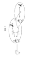
Fig. 1] Fig. 1 is a diagram showing the entire configuration of a mobile communication system according to a first embodiment of the present invention. - [
Fig. 2] Fig. 2 is a functional block diagram of a radio base station according to the first embodiment of the present invention. - [
Fig. 3] Fig. 3 is a diagram illustrating an example of a format of an "RRC Connection Reconfiguration" in the mobile communication system according to the first embodiment of the present invention. - [
Fig. 4] Fig. 4 is a diagram illustrating an example of a method for notifying a subframe pattern in a mobile communication system according to the first embodiment of the present invention. - [
Fig. 5] Fig. 5 is a functional block diagram of a relay node according to the first embodiment of the present invention. - [
Fig. 6] Fig. 6 is a sequence diagram illustrating an operation of a mobile communication system according to the first embodiment of the present invention. - [
Fig. 7] Fig. 7 is a sequence diagram illustrating an operation of a mobile communication system according to a first modification of the first embodiment of the present invention. - With reference to
Fig. 1 through Fig. 5 , the configuration of a mobile communication system according to a first embodiment of the present invention will be explained. - As illustrated in
Fig. 1 , the mobile communication system according to the present embodiment is an LTE-Advanced mobile communication system, and includes a core node (e.g., a gateway device S-GW, a mobile switching center MME and the like) in a core network node, a radio base station DeNB, a relay node RN and the like. - Here, in the example of
Fig. 1 , a Uu radio bearer is set between the radio base station DeNB and the mobile station UE, a Un radio bearer is set between the radio base station DeNB and the relay node RN, and the Uu radio bearer is set between the relay node RN and the mobile station UE. - Further, it is assumed that SFN (System Frame Number) synchronization has been made between the radio base station DeNB and the relay node RN. That is, the relay node RN is configured to make synchronization for the radio base station DeNB at an SFN level based on SFN included in broadcast information transmitted by the radio base station DeNB.
- Furthermore, the configuration is such that when the SFN synchronization is not made between the radio base station DeNB and the relay node RN, the radio base station DeNB detects the number of frames by which an SFN of a radio frame transmitted by the radio base station DeNB and an SFN of a radio frame transmitted by the relay node RN are shifted from each other at a same time (a shift of an SFN between the relay node RN and a second radio base station S-DeNB).
- Further, the radio base station DeNB and the relay node RN are configured to transmit uplink signals and downlink signals using a time division multiplexing scheme.
- As illustrated in
Fig. 2 , the radio base station DeNB includes areception unit 11, atransmission unit 12, ascheduling unit 13, and adetermination unit 14. - The
reception unit 11 is configured to receive uplink signals transmitted from the relay node RN via the Un radio bearer, uplink signals transmitted from the mobile station UE via the Uu radio bearer, and downlink signals transmitted from the core node CN. - The
transmission unit 12 is configured to transmit downlink signals to the relay node RN via the Un radio bearer, downlink signals to the mobile station UE via the Uu radio bearer, and uplink signals to the core node CN. - Furthermore, when a predetermined trigger is detected, the
transmission unit 12 may be configured to notify the relay node RN of a transmission timing of an MBSFN (Multicast Broadcast Single Frequency Network) subframe by an "RRC Connection Reconfiguration". - For example, as illustrated in
Fig. 3 , thetransmission unit 12 may also set an "MBSFN subframe assignment pattern (refer toFig. 4 )" in a "criticalExtensionsFuture"(X) in an information element "criticalExtensions" in the "RRC Connection Reconfiguration", wherein the MBSFN subframe assignment pattern indicates the transmission timing of the MBSFN subframe. - Here, the MBSFN subframe is a subframe used in communication for MBSFN. In addition, in the present specification, the MBSFN subframe also includes an MBSFN subframe defined such that an OFDM symbol for a control signal called "Blank subframe," in the 3GPP meeting is not transmitted.
- Furthermore, the "RRC Connection Reconfiguration" indicates a signal for changing the configuration of an RRC connection between the radio base station DeNB and the relay node RN.
- For example, when modification conditions of an RRC connection having been set in advance in the radio base station DeNB are satisfied, the
transmission unit 12 may be configured to determine that a predetermined trigger is detected. - The
determination unit 14 is configured to determine the transmission timing of the MBSFN subframe to be notified to the relay node RN. - For example, the
determination unit 14 may be configured to determine the transmission timing of the MBSFN subframe to be notified to the relay node RN in consideration of the number of relay nodes RNs and mobile stations UEs subordinate to the radio base station DeNB, and a traffic amount. - The
scheduling unit 13 is configured to perform scheduling related to the relay node RN and the mobile station UE subordinate to the radio base station DeNB. - Specifically, the
scheduling unit 13 is configured to perform scheduling such that the radio base station DeNB transmits downlink signals to the relay node RN at the transmission timing of the MBSFN subframe. - As illustrated in
Fig. 5 , the relay node RN includes areception unit 21, ascheduling unit 22, and atransmission unit 23. - The
reception unit 21 is configured to receive downlink signals transmitted from the radio base station DeNB via the Un radio bearer, and uplink signals transmitted from the mobile station UE via the Uu radio bearer. - For example, when the
reception unit 21 may be configured to acquire the transmission timing of the MBSFN subframe from the "RRC Connection Reconfiguration" received in thereception unit 21. - The
scheduling unit 22 is configured to perform scheduling related to the mobile station UE subordinate to the relay node RN. - Specifically, the
scheduling unit 22 is configured to perform scheduling such that the relay node RN transmits downlink signals at a timing other than the transmission timing of the MBSFN subframe. - That is, the
scheduling unit 22 changes the transmission timing of the MBSFN subframe used for scheduling from a timing used until now to a timing notified by the "RRC Connection Reconfiguration". - The
transmission unit 23 is configured to transmit uplink signals to the radio base station DeNB via the Un radio bearer, and transmit downlink signals to the mobile station UE via the Uu radio bearer. - With reference to
Fig. 6 , the operation of the mobile communication system according to the first embodiment of the present invention will be explained. - As illustrated in
Fig. 6 , if a predetermined trigger is detected in step S1001, the radio base station DeNB transmits an "RRC Connection Reconfiguration" for changing the configuration of an RRC connection having already been set to the relay node RN in step S1002, - Here, the radio base station DeNB notifies the relay node RN of a transmission timing of a new MBSFN subframe by the "RRC Connection Reconfiguration".
- In step S1003, the relay node RN transmits an "RRC Connection Reconfiguration Complete" to the radio base station DeNB.
- Then, the relay node RN performs scheduling of a downlink signal at a timing other than the transmission timing of the new MBSFN subframe notified in step S1002.
- In accordance with the mobile communication system according to the first embodiment of the present invention, it is possible to control a resource in the relay node RN in consideration of the number of relay nodes RNs and mobile stations UEs subordinate to the radio base station DeNB, and a traffic amount.
- With reference to
Fig. 7 , the mobile communication system according to a first modification of the first embodiment of the present invention will be explained. The mobile communication system according to the present first modification is explained below by focusing on the differences with the mobile communication system according to the first embodiment of the present invention mentioned above. - In the mobile communication system according to the present first modification, the
transmission unit 12 of the radio base station DeNB may be configured to notify the relay node RN of the transmission timing of the MBSFN subframe by a "Un RN Reconfiguration", instead of the "RRC Connection Reconfiguration". - In addition, the "Un RN Reconfiguration" is a signal used for a procedure newly defined between the radio base station DeNB and the relay node RN.
- Furthermore, the
reception unit 21 of the relay node RN may be configured to acquire the transmission timing of the MBSFN subframe from the above-mentioned "Un RN Reconfiguration". - Hereinafter, with reference to
Fig. 7 , the operation of the mobile communication system according to the present first modification will be explained. - As illustrated in
Fig. 7 , if a predetermined trigger is detected in step S2001, the radio base station DeNB transmits a "Un RN Reconfiguration" for changing the configuration of an RRC connection having already been set to the relay node RN in step S2002. - Here, the radio base station DeNB notifies the relay node RN of a transmission timing of a new MBSFN subframe by the "Un RN Reconfiguration".
- In step S2003, the relay node RN transmits a "Un RN Reconfiguration Complete" to the radio base station DeNB.
- Then, the relay node RN performs scheduling of a downlink signal at a timing other than the transmission timing of the new MBSFN subframe notified in step S2002.
- The characteristics of the present embodiment as described above may be expressed as follows:
- A first characteristic of the present embodiment is that a mobile communication method includes a step A in which, when a predetermined trigger is detected, the radio base station DeNB notifies the relay node RN of a transmission timing (a predetermined timing) of an MBSFN subframe by a signal for changing the configuration of an RRC connection (a connection) that is set between the radio base station DeNB and the relay node RN, a step B in which the radio base station DeNB performs scheduling such that a downlink signal is transmitted to the relay node RN at the transmission timing of the MBSFN subframe, and a step C in which the relay node RN performs scheduling such that a downlink signal is transmitted at a timing other than the transmission timing of the MBSFN subframe.
- A second characteristic of the present embodiment is that the radio base station DeNB includes the
transmission unit 12 configured to notify the relay node RN of a transmission timing of an MBSFN subframe by a signal for changing the configuration of an RRC connection that is set between the radio base station DeNB and the relay node RN when a predetermined trigger is detected, and thescheduling unit 13 configured to perform scheduling such that a downlink signal is transmitted to the relay node RN at the transmission timing of the MBSFN subframe. - A third characteristic of the present embodiment is that the relay node RN includes the
reception unit 21 configured to receive a signal for changing the configuration of an RRC connection that is set between the radio base station DeNB and the relay node RN from the radio base station DeNB, and acquire a transmission timing of an MBSFN subframe from the received signal, and thescheduling unit 22 configured to perform scheduling such that a downlink signal is transmitted at a timing other than the transmission timing of the MBSFN subframe. - In the first to third characteristics of the present embodiment, the above-mentioned signal may include an "RRC Connection Reconfiguration" or a "Un RN Reconfiguration".
- It is noted that the operation of the above-described the radio base station DeNB, the relay node RN, the core node CN or the mobile station UE may be implemented by a hardware, may also be implemented by a software module executed by a processor, and may further be implemented by the combination of the both.
- The software module may be arranged in a storage medium of an arbitrary format such as RAM(Random Access Memory), a flash memory, ROM (Read Only Memory), EPROM (Erasable Programmable ROM), EEPROM (Electronically Erasable and Programmable ROM), a register, a hard disk, a removable disk, and CD-ROM.
- The storage medium is connected to the processor so that the processor can write and read information into and from the storage medium. Such a storage medium may also be accumulated in the processor. The storage medium and processor may be arranged in ASIC. Such the ASPIC may be arranged in the radio base station DeNB, the relay node RN, the core node CN or the mobile station UE. Further, such a storage medium or a processor may be arranged, as a discrete component, in the radio base station DeNB, the relay node RN, the core node CN or the mobile station UE.
- Thus, the present invention has been explained in detail by using the above-described embodiments; however, it is obvious that for persons skilled in the art, the present invention is not limited to the embodiments explained herein. The present invention can be implemented as a corrected and modified mode without departing from the gist and the scope of the present invention defined by the claims. Therefore, the description of the specification is intended for explaining the example only and does not impose any limited meaning to the present invention.
Claims (9)
- A mobile communication method, comprising:a step A in which, when a predetermined trigger is detected, a radio base station notifies a relay node of a predetermined timing by a signal for changing a configuration of a connection that is set between the radio base station and the relay node;a step B in which the radio base station performs scheduling such that a downlink signal is transmitted to the relay node at the predetermined timing; anda step C in which the relay node performs scheduling such that a downlink signal is transmitted at a timing other than the predetermined timing.
- The mobile communication method according to claim 1, wherein
the connection is an RRC connection, and
the signal is an "RRC Connection Reconfiguration". - The mobile communication method according to claim 1 or 2, wherein the predetermined timing is a transmission timing of an MBSFN subframe.
- A radio base station, comprising:a notification unit configured to notify a relay node of a predetermined timing by a signal for changing a configuration of a connection that is set between the radio base station and the relay node when a predetermined trigger is detected; anda scheduling unit configured to perform scheduling such that a downlink signal is transmitted to the relay node at the predetermined timing.
- The radio base station according to claim 4, wherein
the connection is an RRC connection, and
the signal is an "RRC Connection Reconfiguration". - The radio base station according to claim 4 or 5, wherein the predetermined timing is a transmission timing of an MBSFN subframe.
- A relay node, comprising:an acquisition unit configured to receive a signal for changing a configuration of a connection that is set between a radio base station and the relay node from the radio base station, and acquire a predetermined timing from the received signal; anda scheduling unit configured to perform scheduling such that a downlink signal is transmitted at a timing other than the predetermined timing.
- The relay node according to claim 7, wherein
the connection is an RRC connection, and
the signal is an "RRC Connection Reconfiguration". - The relay node according to claim 7 or 8, wherein the predetermined timing is a transmission timing of an MBSFN subframe.
Applications Claiming Priority (2)
| Application Number | Priority Date | Filing Date | Title |
|---|---|---|---|
| JP2009148134A JP4749480B2 (en) | 2009-06-22 | 2009-06-22 | Mobile communication method, radio base station, and relay node |
| PCT/JP2010/060549 WO2010150776A1 (en) | 2009-06-22 | 2010-06-22 | Mobile communication method, wireless base station, and relay node |
Publications (2)
| Publication Number | Publication Date |
|---|---|
| EP2448311A1 true EP2448311A1 (en) | 2012-05-02 |
| EP2448311A4 EP2448311A4 (en) | 2014-07-02 |
Family
ID=43386545
Family Applications (1)
| Application Number | Title | Priority Date | Filing Date |
|---|---|---|---|
| EP10792094.4A Withdrawn EP2448311A4 (en) | 2009-06-22 | 2010-06-22 | MOBILE COMMUNICATION METHOD, WIRELESS BASE STATION AND RELAY N UD |
Country Status (10)
| Country | Link |
|---|---|
| US (1) | US9184831B2 (en) |
| EP (1) | EP2448311A4 (en) |
| JP (1) | JP4749480B2 (en) |
| KR (1) | KR101365651B1 (en) |
| CN (1) | CN102804837B (en) |
| AU (1) | AU2010263667B2 (en) |
| MX (1) | MX2012000154A (en) |
| RU (1) | RU2501184C2 (en) |
| WO (1) | WO2010150776A1 (en) |
| ZA (1) | ZA201200056B (en) |
Families Citing this family (3)
| Publication number | Priority date | Publication date | Assignee | Title |
|---|---|---|---|---|
| JP5187909B2 (en) * | 2009-10-05 | 2013-04-24 | 株式会社エヌ・ティ・ティ・ドコモ | Mobile communication method and relay node |
| KR102120106B1 (en) * | 2011-10-13 | 2020-06-17 | 엘지전자 주식회사 | Method in which a terminal transceives a signal in a wireless communication system and apparatus for same |
| US20230094704A1 (en) * | 2019-10-11 | 2023-03-30 | Ntt Docomo, Inc. | Terminal and communication method |
Family Cites Families (15)
| Publication number | Priority date | Publication date | Assignee | Title |
|---|---|---|---|---|
| JP3866909B2 (en) * | 2000-08-10 | 2007-01-10 | 株式会社エヌ・ティ・ティ・ドコモ | Wireless relay device |
| KR100338637B1 (en) | 2000-08-16 | 2002-05-30 | 윤종용 | Apparatus for setting up a radio resource control call and releasing it in international mobile telecommunication-2000 of using general packet radio service and method thereof |
| JP2002077979A (en) * | 2000-08-25 | 2002-03-15 | Matsushita Electric Ind Co Ltd | Wireless relay device, wireless relay method, and recording medium |
| KR100548344B1 (en) * | 2003-05-13 | 2006-02-02 | 엘지전자 주식회사 | RRC connection method in mobile communication system |
| JP4494134B2 (en) * | 2004-09-01 | 2010-06-30 | Kddi株式会社 | Wireless communication system, relay station apparatus and base station apparatus |
| JP5125027B2 (en) * | 2006-08-17 | 2013-01-23 | 富士通株式会社 | Radio relay communication method, radio base station and radio relay station in radio communication system |
| EP2140721A2 (en) * | 2007-04-30 | 2010-01-06 | InterDigital Technology Corporation | Mobility procedures and differentiated charging in home node-bs |
| KR20090029623A (en) * | 2007-09-18 | 2009-03-23 | 엘지전자 주식회사 | System Information Acquisition Method in Wireless Communication System |
| KR101441138B1 (en) * | 2007-09-28 | 2014-09-18 | 엘지전자 주식회사 | A method for performing uplink time synchronization in a wireless communication system |
| US8335176B2 (en) * | 2008-04-07 | 2012-12-18 | Qualcomm Incorporated | Transmission of overhead channels with timing offset and blanking |
| KR101245505B1 (en) * | 2008-12-26 | 2013-03-25 | 후지쯔 가부시끼가이샤 | Radio communication system |
| KR101294517B1 (en) * | 2009-04-21 | 2013-08-07 | 엘지전자 주식회사 | Method of utilizing a relay node in wireless communication system |
| US8289895B2 (en) * | 2009-04-24 | 2012-10-16 | Research In Motion Limited | Relay link HARQ operation |
| KR101710394B1 (en) * | 2009-05-08 | 2017-02-27 | 엘지전자 주식회사 | Method and apparatus of transmitting channel information for reference signal |
| US9184882B2 (en) * | 2009-06-16 | 2015-11-10 | Interdigital Patent Holdings, Inc. | Method and apparatus for synchronous HARQ operation and interference avoidance |
-
2009
- 2009-06-22 JP JP2009148134A patent/JP4749480B2/en active Active
-
2010
- 2010-06-22 RU RU2012100384/07A patent/RU2501184C2/en active
- 2010-06-22 EP EP10792094.4A patent/EP2448311A4/en not_active Withdrawn
- 2010-06-22 MX MX2012000154A patent/MX2012000154A/en active IP Right Grant
- 2010-06-22 US US13/379,744 patent/US9184831B2/en active Active
- 2010-06-22 KR KR1020117031169A patent/KR101365651B1/en active Active
- 2010-06-22 AU AU2010263667A patent/AU2010263667B2/en active Active
- 2010-06-22 WO PCT/JP2010/060549 patent/WO2010150776A1/en not_active Ceased
- 2010-06-22 CN CN201080027954.1A patent/CN102804837B/en active Active
-
2012
- 2012-01-04 ZA ZA2012/00056A patent/ZA201200056B/en unknown
Non-Patent Citations (4)
| Title |
|---|
| NORTEL: "Discussion paper on the control channel and data channel optimization for relay link", 3GPP DRAFT; R1-091384(NORTEL-CONTROL_DATA_RELAY_LINK_D ESIGN_IN_LTE-A), 3RD GENERATION PARTNERSHIP PROJECT (3GPP), MOBILE COMPETENCE CENTRE ; 650, ROUTE DES LUCIOLES ; F-06921 SOPHIA-ANTIPOLIS CEDEX ; FRANCE, no. Seoul, Korea; 20090317, 17 March 2009 (2009-03-17), XP050338973, [retrieved on 2009-03-17] * |
| QUALCOMM EUROPE: "Introduction of blank subframe indication into SIB2", 3GPP DRAFT; R2-086823, 3RD GENERATION PARTNERSHIP PROJECT (3GPP), MOBILE COMPETENCE CENTRE ; 650, ROUTE DES LUCIOLES ; F-06921 SOPHIA-ANTIPOLIS CEDEX ; FRANCE, no. Prague, Czech Republic; 20081113, 13 November 2008 (2008-11-13), XP050321632, [retrieved on 2008-11-13] * |
| See also references of WO2010150776A1 * |
| TEXAS INSTRUMENTS: "On the design of relay node for LTE-advanced", 3GPP DRAFT; R1-090290 L2 RELAY V9, 3RD GENERATION PARTNERSHIP PROJECT (3GPP), MOBILE COMPETENCE CENTRE ; 650, ROUTE DES LUCIOLES ; F-06921 SOPHIA-ANTIPOLIS CEDEX ; FRANCE, no. Ljubljana; 20090107, 7 January 2009 (2009-01-07), XP050318214, [retrieved on 2009-01-07] * |
Also Published As
| Publication number | Publication date |
|---|---|
| KR101365651B1 (en) | 2014-02-19 |
| CN102804837B (en) | 2016-05-04 |
| AU2010263667A1 (en) | 2012-02-09 |
| AU2010263667B2 (en) | 2013-09-26 |
| WO2010150776A1 (en) | 2010-12-29 |
| EP2448311A4 (en) | 2014-07-02 |
| KR20120027403A (en) | 2012-03-21 |
| RU2012100384A (en) | 2013-07-27 |
| CN102804837A (en) | 2012-11-28 |
| JP4749480B2 (en) | 2011-08-17 |
| RU2501184C2 (en) | 2013-12-10 |
| MX2012000154A (en) | 2012-02-01 |
| US9184831B2 (en) | 2015-11-10 |
| JP2011004372A (en) | 2011-01-06 |
| ZA201200056B (en) | 2013-03-27 |
| US20120147809A1 (en) | 2012-06-14 |
Similar Documents
| Publication | Publication Date | Title |
|---|---|---|
| US8885543B2 (en) | Mobile communication method and relay node | |
| JP6959238B2 (en) | Communications system | |
| EP2547137B1 (en) | Communication section setting method, relay station and mobile communication system | |
| US9832768B2 (en) | Mobile communication method and radio base station | |
| CA2755900C (en) | Mobile communication method, radio base station, and relay node | |
| US8913545B2 (en) | Mobile communication system and radio base station | |
| US9253708B2 (en) | Mobile communication method, relay node, and wireless base station | |
| AU2010263667B2 (en) | Mobile communication method, wireless base station, and relay node |
Legal Events
| Date | Code | Title | Description |
|---|---|---|---|
| PUAI | Public reference made under article 153(3) epc to a published international application that has entered the european phase |
Free format text: ORIGINAL CODE: 0009012 |
|
| 17P | Request for examination filed |
Effective date: 20120120 |
|
| AK | Designated contracting states |
Kind code of ref document: A1 Designated state(s): AL AT BE BG CH CY CZ DE DK EE ES FI FR GB GR HR HU IE IS IT LI LT LU LV MC MK MT NL NO PL PT RO SE SI SK SM TR |
|
| DAX | Request for extension of the european patent (deleted) | ||
| A4 | Supplementary search report drawn up and despatched |
Effective date: 20140604 |
|
| RIC1 | Information provided on ipc code assigned before grant |
Ipc: H04W 56/00 20090101ALI20140528BHEP Ipc: H04B 7/155 20060101ALI20140528BHEP Ipc: H04W 16/26 20090101AFI20140528BHEP |
|
| 17Q | First examination report despatched |
Effective date: 20170517 |
|
| STAA | Information on the status of an ep patent application or granted ep patent |
Free format text: STATUS: THE APPLICATION IS DEEMED TO BE WITHDRAWN |
|
| 18D | Application deemed to be withdrawn |
Effective date: 20170928 |