EP2448066A1 - Terminal containing section for an electrical junction box and electrical junction box therewith - Google Patents
Terminal containing section for an electrical junction box and electrical junction box therewith Download PDFInfo
- Publication number
- EP2448066A1 EP2448066A1 EP11163636A EP11163636A EP2448066A1 EP 2448066 A1 EP2448066 A1 EP 2448066A1 EP 11163636 A EP11163636 A EP 11163636A EP 11163636 A EP11163636 A EP 11163636A EP 2448066 A1 EP2448066 A1 EP 2448066A1
- Authority
- EP
- European Patent Office
- Prior art keywords
- terminal
- containing section
- connecting terminal
- ribs
- terminal containing
- Prior art date
- Legal status (The legal status is an assumption and is not a legal conclusion. Google has not performed a legal analysis and makes no representation as to the accuracy of the status listed.)
- Granted
Links
- 230000002542 deteriorative effect Effects 0.000 abstract description 4
- 238000013459 approach Methods 0.000 description 7
- 230000007423 decrease Effects 0.000 description 6
- 239000002184 metal Substances 0.000 description 4
- 229910052751 metal Inorganic materials 0.000 description 4
- 229920005989 resin Polymers 0.000 description 3
- 239000011347 resin Substances 0.000 description 3
- 230000008878 coupling Effects 0.000 description 2
- 238000010168 coupling process Methods 0.000 description 2
- 238000005859 coupling reaction Methods 0.000 description 2
- 230000002939 deleterious effect Effects 0.000 description 2
- 230000006866 deterioration Effects 0.000 description 2
- 238000004080 punching Methods 0.000 description 2
- 230000000452 restraining effect Effects 0.000 description 2
- RYGMFSIKBFXOCR-UHFFFAOYSA-N Copper Chemical compound [Cu] RYGMFSIKBFXOCR-UHFFFAOYSA-N 0.000 description 1
- 238000005452 bending Methods 0.000 description 1
- 229910052802 copper Inorganic materials 0.000 description 1
- 239000010949 copper Substances 0.000 description 1
- 230000003247 decreasing effect Effects 0.000 description 1
- 238000003780 insertion Methods 0.000 description 1
- 230000037431 insertion Effects 0.000 description 1
- 230000000670 limiting effect Effects 0.000 description 1
- 230000002829 reductive effect Effects 0.000 description 1
- 230000002441 reversible effect Effects 0.000 description 1
- 229910001220 stainless steel Inorganic materials 0.000 description 1
- 239000010935 stainless steel Substances 0.000 description 1
- 229920003002 synthetic resin Polymers 0.000 description 1
- 239000000057 synthetic resin Substances 0.000 description 1
- 238000004804 winding Methods 0.000 description 1
Images



Classifications
-
- H—ELECTRICITY
- H01—ELECTRIC ELEMENTS
- H01R—ELECTRICALLY-CONDUCTIVE CONNECTIONS; STRUCTURAL ASSOCIATIONS OF A PLURALITY OF MUTUALLY-INSULATED ELECTRICAL CONNECTING ELEMENTS; COUPLING DEVICES; CURRENT COLLECTORS
- H01R13/00—Details of coupling devices of the kinds covered by groups H01R12/70 or H01R24/00 - H01R33/00
- H01R13/40—Securing contact members in or to a base or case; Insulating of contact members
- H01R13/42—Securing in a demountable manner
- H01R13/422—Securing in resilient one-piece base or case, e.g. by friction; One-piece base or case formed with resilient locking means
- H01R13/4223—Securing in resilient one-piece base or case, e.g. by friction; One-piece base or case formed with resilient locking means comprising integral flexible contact retaining fingers
-
- H—ELECTRICITY
- H01—ELECTRIC ELEMENTS
- H01R—ELECTRICALLY-CONDUCTIVE CONNECTIONS; STRUCTURAL ASSOCIATIONS OF A PLURALITY OF MUTUALLY-INSULATED ELECTRICAL CONNECTING ELEMENTS; COUPLING DEVICES; CURRENT COLLECTORS
- H01R13/00—Details of coupling devices of the kinds covered by groups H01R12/70 or H01R24/00 - H01R33/00
- H01R13/02—Contact members
- H01R13/10—Sockets for co-operation with pins or blades
- H01R13/11—Resilient sockets
- H01R13/112—Resilient sockets forked sockets having two legs
-
- H—ELECTRICITY
- H01—ELECTRIC ELEMENTS
- H01R—ELECTRICALLY-CONDUCTIVE CONNECTIONS; STRUCTURAL ASSOCIATIONS OF A PLURALITY OF MUTUALLY-INSULATED ELECTRICAL CONNECTING ELEMENTS; COUPLING DEVICES; CURRENT COLLECTORS
- H01R13/00—Details of coupling devices of the kinds covered by groups H01R12/70 or H01R24/00 - H01R33/00
- H01R13/02—Contact members
- H01R13/15—Pins, blades or sockets having separate spring member for producing or increasing contact pressure
- H01R13/18—Pins, blades or sockets having separate spring member for producing or increasing contact pressure with the spring member surrounding the socket
-
- H—ELECTRICITY
- H01—ELECTRIC ELEMENTS
- H01R—ELECTRICALLY-CONDUCTIVE CONNECTIONS; STRUCTURAL ASSOCIATIONS OF A PLURALITY OF MUTUALLY-INSULATED ELECTRICAL CONNECTING ELEMENTS; COUPLING DEVICES; CURRENT COLLECTORS
- H01R9/00—Structural associations of a plurality of mutually-insulated electrical connecting elements, e.g. terminal strips or terminal blocks; Terminals or binding posts mounted upon a base or in a case; Bases therefor
- H01R9/22—Bases, e.g. strip, block, panel
Definitions
- the present invention has been made under consideration of the above problems and aims to solve at least one of them.
- Dimensions of the projecting plates 48a and 48b that protrude from the inner surfaces 20b and 20d are substantially constant through entire lengths of the projecting plates 48a and 48b.
- the inner surfaces 20b and 20d are provided with grooves 52 (see Figures 2 and 5 ) between the pair of the projecting plates 48a and 48b.
- the projecting plates 48a and 48b are spaced apart from each other in the facing direction of the inner surfaces 20a and 20c (in the upper and lower directions in Figure 3 ).
- the projecting plates 48a and 48b are integrally provided with the side ribs 50a and 50b, respectively.
- the side ribs 50a and 50b extend through the entire lengths of the projecting plates 48a and 48b in the extending direction of the terminal containing section 14.
- the side ribs 50a and 50b are provided on end edges near the other projecting plate 48a (48b) on projecting end surfaces of the projecting plates 48a and 48b from the inner surface 20b and 20d.
- the outer ribs 24a to 24e are brought in to contact with the faces of the pinching pieces 66, 66 from the outside in the widening direction and over wide areas in the longitudinal direction of the outer ribs 24a to 24e.
- the outer ribs 24a to 24e it is possible for the outer ribs 24a to 24e to stably prevent the pinching pieces 66, 66 from being excessively deformed and it is possible to ensure a connecting performance of the pinching pieces 66, 66 for a long period in time.
- the outer ribs 24a, 24c, 24d, and 24e contact with the widening stopper pieces 76 of the connecting terminal 56.
Landscapes
- Connection Or Junction Boxes (AREA)
- Connector Housings Or Holding Contact Members (AREA)
Abstract
Description
- This invention generally relates to a terminal containing section in which a connecting terminal is inserted and held, as well as to an electrical junction box that includes such a terminal containing section. More particularly the invention relates to a terminal containing section for an electrical junction box in which a tapered connecting terminal is inserted and held, as well as to an electrical junction box that includes such a terminal containing section.
- An electrical junction box, such as a relay box or a fuse box, may be provided with a connecting terminal to be connected to an electrical component, such as a relay or a fuse. For example, as disclosed in
JP 2003-274538 A - The connecting terminal may be formed into various kinds of configurations. For example, as disclosed in
JP 2008-34402 A - However, the connecting terminal disclosed in
JP 2008-34402 A - Further, the interior of the terminal containing section may be tapered so as to correspond to the tapered connecting terminal in order to prevent the connecting terminal from staggering within the terminal containing section. However, in such structure, since the pinching pieces of the connecting terminal contact with an inner surface of the terminal containing section and the pinching pieces cannot be widened sufficiently when the electrical component is coupled to the connecting terminal, there is a possibility that the connection will be deteriorated. Also, when the connecting terminal is assembled in the terminal containing section, the connecting terminal rubs the inner surface of the terminal containing section, thereby requiring a large inserting force for the connecting terminal. This will deteriorate workability in assembly. Furthermore, there is a problem that it is difficult to form a tapered inner surface in the terminal containing section and an amount of resin increases on account of a narrow interior of the terminal containing section.
- The present invention has been made under consideration of the above problems and aims to solve at least one of them.
- Accordingly, the present invention provides a terminal containing section for an electrical junction box that positions and stably holds a tapered connecting terminal without deteriorating workability in the connection of the connecting terminal. The present invention also provides an electrical junction box including at least one such terminal containing section.
- Thus, according to a first aspect of the invention, a terminal containing section is provided in which a connecting terminal to be connected to an electrical component is inserted and held. The connecting terminal may be tapered and may be provided with a pair of pinching pieces that are stacked on each other. A tab terminal of the electrical component is pinched between the pair of pinching pieces. The terminal containing section is provided on an inner surface thereof with a plurality of outer ribs and a plurality of side ribs that protrude from the inner surface and extend in an inserting direction of the connecting terminal. Protruding dimensions of the outer ribs gradually increase as the outer ribs extend toward a distal end side of the connecting terminal. The outer ribs pinch the connecting terminal from both outer sides thereof in a stacking direction of the pair of pinching pieces while the side ribs pinch the connecting terminal from both outer sides thereof in a direction perpendicular to the stacking direction, thereby positioning the connecting terminal in the terminal containing section.
- According to the invention, the connecting terminal accommodated in the terminal containing section may be pinched by the outer ribs and side ribs provided on the inner surface of the terminal containing section. Particularly, the protruding dimensions of the outer ribs gradually increase as the outer ribs extend toward the distal end side of the connecting terminal. Thus, it is possible for the interior of the terminal containing section to accord with the tapered connecting terminal by making the protruding dimensions of the outer ribs gradually increase in connection with the structure in which the pinching pieces of the connecting terminal are gradually spaced apart from the inner surface of the terminal containing section. As a result, even if the connecting terminal is tapered, the outer ribs and side ribs can reduce the clearance between the connecting terminal and the inner surface of the terminal containing section and can position the connecting terminal in the terminal containing section while restraining the connecting terminal from staggering in the terminal containing section. Furthermore, the connecting terminal can be pinched by the outer ribs and side ribs in two orthogonal directions. Thus, it is also possible to effectively prevent the connecting terminal from staggering in a rotary direction.
- Since the outer ribs pinch the pinching pieces from their both sides in opening and closing directions of the pinching pieces, it is possible to prevent the pinching pieces from being widened excessively while ensuring an amount of widening deformation of the pinching pieces required when the electrical component is coupled to the connecting terminal. At the same time, since the side ribs pinch the pinching pieces from their both sides in a direction perpendicular to the opening and closing directions, it is possible to prevent the connecting terminal from staggering in the terminal containing section while restraining the opening and closing operations of the pinching pieces from being deteriorated. Consequently, it is possible to ensure workability in connection of the connecting terminal and it is possible to stably position the connecting terminal in the terminal containing section.
- When the connecting terminal is inserted into the terminal containing section, the outer ribs and side ribs can reduce a sliding area between the connecting terminal and the inner surface of the terminal containing section. Thus, it is possible for a small insertion force to easily insert the connecting terminal into the terminal containing section and it is possible to prevent the connecting terminal from staggering in the terminal containing section. Furthermore, since the outer ribs and side ribs merely protrude from the inner surface of the terminal containing section, it is easy to form the interior of the terminal containing section and it is possible to reduce an amount of resin in comparison with the case where the entire interior of the terminal containing section is narrowed in connection with the tapered connecting terminal.
- Preferably, the terminal containing section may be provided on the inner surface with an engaging and holding section that latches the connecting terminal. The connecting terminal may be pinched between the engaging and holding section and one of the outer ribs.
- Since the engaging and holding section can latch the connecting terminal, it is possible to hold the connecting terminal in the terminal containing section. Since the outer rib is opposed to the engaging and holding section and the engaging and holding section and outer ribs pinch the connecting terminal, it is possible to hold the connecting terminal in the terminal containing section more stably.
- Preferably, the outer ribs are larger than the side ribs, i.e. may be greater than the side ribs over the entire lengths of the outer ribs.
- Accordingly, the larger or greater outer ribs in the opening direction of the pinching pieces can stably prevent the pinching pieces from being widened excessively in the opening direction while the smaller side ribs in a side direction of the pinching pieces can prevent the pinching pieces from staggering in the terminal containing section without deteriorating the opening and closing actions of the pinching pieces.
- Preferably, the outer ribs may be brought into contact along a planar surface of each of the pinching pieces in a first direction, while the side ribs are brought into contact with an edge of each of the planar surfaces of the pinching pieces in the direction perpendicular to the first direction. That is, the outer ribs may be brought into contact with the faces of the pinching pieces of the connecting terminal, while the side ribs may be brought into point contact with the pinching pieces.
- Accordingly, since the outer ribs may be brought into contact with the faces of the pinching pieces, it is possible to more effectively prevent the pinching pieces from being widened excessively. At the same time, since the side ribs may be brought into point contact with the pinching pieces, it is possible to reduce a contact area between the side ribs and the pinching pieces and it is possible to reduce deterioration of the pinching pieces when the pinching pieces are opened.
- The inner surface of the terminal containing section may be provided with the outer ribs and side ribs, and the protruding dimensions of the outer ribs from the inner surface gradually increase as the outer ribs extend toward the distal end side of the connecting terminal. The outer ribs and side ribs pinch the connecting terminal in two orthogonal directions. Thus, it is possible to stably position and hold the connecting terminal in the terminal containing section. Furthermore, since the outer ribs pinch the pinching pieces from their both sides in the opening and closing directions of the pinching pieces, it is possible to prevent the pinching pieces from being widened excessively while ensuring an amount of widening the pinching pieces required for connecting the electrical component to the connecting terminal. At the same time, since the side ribs pinch the pinching pieces from their both sides in the direction perpendicular to the opening and closing directions, it is possible to lower deterioration of the opening and closing actions of the pinching pieces. In result, it is possible to position the connecting terminal while ensuring workability in connection of the connecting terminal.
- According to a further, second aspect of the invention, there is also provided an electrical junction box including at least one terminal containing section according to the first aspect.
- The invention and at least part of the advantages coming along therewith will now be described by way of merely illustrative and not limiting examples referring to the accompanying drawings, in which:
-
Figure 1 is a top plan view of an electrical junction box according to an exemplary embodiment; -
Figure 2 is a top plan view of a terminal containing section provided in the electrical junction box shown inFigure 1 ; -
Figure 3 is a bottom plan view of the terminal containing section shown inFigure 2 ; -
Figure 4 is a cross section view of the terminal containing section taken along lines IV-IV inFigure 2 ; -
Figure 5 is a longitudinal section view of the terminal containing section taken along lines V-V inFigure 2 ; -
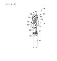
Figure 6 is a perspective view of a connecting terminal to be accommodated in the terminal containing section shown inFigure 2 ; -
Figure 7 is a rear side elevation view of the connecting terminal shown inFigure 6 ; -
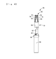
Figure 8 is a side elevation view of the connecting terminal shown inFigure 6 ; -
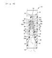
Figure 9 is a longitudinal section view of the connecting terminal corresponding toFigure 4 , illustrating the connecting terminal accommodated in the terminal containing section; and -
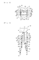
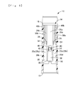
Figure 10 is a longitudinal section view of the connecting terminal corresponding toFigure 5 , illustrating the connecting terminal accommodated in the terminal containing section. - Referring now to the drawings, exemplary embodiments of a terminal containing section and an electrical junction box, respectively, will be described below.
-
Figure 1 shows anelectrical junction box 10 in an exemplary embodiment. Theelectrical junction box 10 is formed into a substantially rectangular box-like configuration made of a synthetic resin. Theelectrical junction box 10 is provided with arelay mounting unit 12 on which an electrical component (not shown) such as a relay is mounted. Therelay mounting unit 12 is provided with at least oneterminal containing section 14, however usually with a plurality of suchterminal containing sections 14 at positions corresponding to tab terminals provided on the relays. -
Figures 2 to 5 show each of theterminal containing sections 14. Eachterminal containing section 14 extends in a thickness direction (upper and lower directions inFigures 4 and5 ) and defines a through-hole that is open in a front surface and a rear surface of theelectrical junction box 10. An extending direction of theterminal containing section 14 accords with an inserting direction of a connecting terminal 56 (mentioned after) so that the connectingterminal 56 is inserted into theelectrical junction box 10 from arear surface 18 to afront surface 16. Eachterminal containing section 14 is formed into a substantially rectangular through-hole havinginner surfaces 20a to 20d. Theinner surfaces inner surfaces inner surfaces - As shown in
Figure 4 , theinner surface 20a is provided at a side of thefront surface 16 with a steppedsurface 22 that protrudes vertically toward an inside of theterminal containing section 14. The steppedsurface 22 makes an opening small at the side of thefront surface 16 of theterminal containing section 14. Theinner surface 20a is integrally provided with a plurality ofouter ribs 24a to 24c (three outer ribs in the present exemplary embodiment, as shown inFigure 3 ). - Since the
outer ribs 24a to 24c are the same configurations as one another, theouter rib 24b shown inFigure 4 is described below as an example out of them. Theouter rib 24b protrudes from theinner surface 20a. Theouter rib 24b has a length that extends from an intermediate part of theinner surface 20a to the steppedsurface 22 in an extending direction of the terminal containing section 14 (in upper and lower directions inFigure 4 ). Theouter rib 24b extends straightly in the extending direction of theterminal containing section 14. Theouter rib 24b has a dimension in height from theinner surface 20a that increases gradually to the steppedsurface 22 at a distal end side of an inserting direction of a connecting terminal 56 (mentioned after). As shown inFigure 3 , theouter rib 24b is formed so that a protruding end of theouter rib 24b from theinner surface 20a is a semicircular shape in cross section. Theouter rib 24b is tapered so that a dimension in width at a distal end protruding from theinner surface 20a is smaller than a dimension in width at a side of theinner surface 20a. Furthermore, as shown inFigure 5 , it will be apparent fromouter ribs outer rib 24b that theouter rib 24b is tapered so that a dimension in width (right and left directions inFigure 5 ) decreases gradually toward therear surface 18. - As shown in
Figure 3 , theouter rib 24b out of theouter ribs Figure 3 ). Theouter ribs outer rib 24b so that theouter ribs outer rib 24b. Theouter ribs Figure 4 ). - On the other hand, as shown in
Figures 2 ,4 , and5 , theinner surfaces walls terminal containing section 14. As shown inFigure 2 , the projectingwalls inner surfaces walls walls walls inner surface 20a define theinner surface 20c of theterminal containing section 14. - The projecting
walls inner surface 20c with theouter ribs outer ribs outer ribs 24a to 24c on theinner surface 20a. Theouter ribs inner surfaces walls Figure 4 , theouter ribs outer ribs 24a to 24c in the extending direction of the terminal containing section 14 (in the upper and lower directions inFigure 4 ) and extend straightly in the extending direction of theterminal containing section 14. Theouter ribs inner surface 20c so that the dimensions increase gradually from the front end edge at the side of therear surface 18 to the side of thefront surface 16 that is the front end side in the connecting terminal 56 (mentioned after), as is the case with theouter ribs 24a to 24c. Furthermore, theouter ribs surface 22 on the inner surface 22a in the extending direction of theterminal containing section 14 to thefront surface 16 so that theouter ribs Figure 3 , theouter ribs outer ribs terminal containing section 14. - As shown in
Figure 4 , the projectingwalls rear surface 18 on theinner surface 20c withslant surfaces inner surface 20a as the slant surfaces 30 and 30 approach to therear surface 18. On the other hand, theinner surface 20a is provided with asimilar slant surface 32. Since the slant surfaces 30 and 32 are faced to one another at the same positions in the extending direction of theterminal containing section 14, theterminal containing section 14 is widened at the side of therear surface 18 by the slant surfaces 30 and 32. Accordingly, a distance between theinner surfaces rear surface 18 to thefront surface 16 from the slant surfaces 30 and 32, and then is substantially constant from the slant surfaces 30 and 32 to theouter ribs 24a to 24e, and again decreases gradually from theouter ribs 24a to 24e. - A
lance 34 is provided in a space between the projectingwalls lance 34 can adopt any one of publicly known configurations in the prior art. Theterminal containing section 14 in the present embodiment is provided at a position remote from theinner surface 20c with a secondinner surface 20e that is opposed to theinner surface 20a. Thelance 34 protrudes from the secondinner surface 20e. Thelance 34 protrudes from the secondinner surface 20e at a connectingportion 36 and has aleaf spring section 38 that extends from the connectingportion 36 to thefront surface 16. Theleaf spring section 38 is inclined so that theleaf spring section 38 approaches to theinner surface 20a as thesection 38 extends from the connectingportion 36 to thefront surface 16. - An
engagement projection 40 that protrudes toward theinner surface 20a is integrally provided on a projecting end from the connectingportion 36 on theleaf spring section 38. A surface of theengagement projection 40 at a side of therear surface 18 defines aslant guide surface 42 in which a dimension projecting from theleaf spring section 38 increases gradually as theslant guide surface 42 extends from the side of therear surface 18 to the side of thefront surface 16. On the other hand, a surface of theengagement projection 40 at the side of thefront surface 16 defines anengagement surface 44 that inclines in the same direction as theslant guide surface 42 by a slant angle smaller than that of theslant guide surface 42. Theleaf spring section 38 is provided on a projecting end edge with anoperation piece 46 having a triangular shape in cross section so that theoperation piece 46 inclines and is spaced apart from theengagement projection 40. Under an engagement condition of the connecting terminal 56 (mentioned after) with theterminal containing section 14, a suitable tool or the like is inserted into theterminal containing section 14 from the side of thefront surface 16 to operate theoperation piece 46, if required, then thelance 34 is brought into approach to the secondinner surface 20e. In result, it is possible to release an engagement condition between thelance 34 and the connectingterminal 56. As shown inFigure 3 , since thelance 34 is disposed between theouter ribs lance 34 is opposed to theouter rib 24b. - On the other hand, as shown in
Figure 5 , theinner surfaces terminal containing section 14 are substantially flat surfaces through a whole length of theterminal containing section 14. As shown inFigure 3 , a pair of projectingplates inner surfaces Side ribs plates - The projecting
plates inner surfaces plate 48a is disposed at the side of theinner surface 20a while the projectingplate 48b is disposed at the side of theinner surface 20c. The projectingplates inner surfaces terminal containing section 14. As shown inFigure 5 , the projectingplates terminal containing section 14 at the same positions of theouter ribs outer ribs plates inner surfaces plates inner surfaces Figures 2 and5 ) between the pair of the projectingplates plates inner surfaces Figure 3 ). - As already stated, the projecting
plates side ribs side ribs plates terminal containing section 14. As shown inFigures 3 and 4 , theside ribs plate 48a (48b) on projecting end surfaces of the projectingplates inner surface plate 48a at the side of thefront surface 16 is connected to the steppedsurface 22 while the end edge of theside rib 50a at the side of thefront surface 16 is connected to the projecting end edge of the steppedsurface 22 from theinner surface 20a. - The
side ribs plates side ribs side ribs Figure 3 ) are smaller than those of the sides of theinner surfaces Figure 4 , theside ribs front ends 54 at the side of therear surface 18 so that dimensions in width decrease toward therear surface 18. Theside ribs front surface 16. - As shown in
Figures 4 and5 , end edges of theside ribs outer ribs 24a to 24e at the side of therear surface 18 are disposed at the same positions in the extending direction of theterminal containing section 14. As shown inFigures 3 and5 , cross section areas of theouter ribs 24a to 24e are set to be greater than those of theside ribs terminal containing section 14 through the entire lengths of theouter ribs 24a to 24e. That is, theouter ribs 24a to 24e have dimensions in width and cross section areas than those of theside ribs - The connecting
terminal 56 shown in, for example,Figures 6 to 8 is inserted into theterminal containing section 14 constructed above. The connectingterminal 56 will be briefly described below. - The connecting
terminal 56 is coupled to an end of anelectrical cable 58. The connectingterminal 56 is provided with acaulking piece 60 for anelectrical cable 58 and acaulking piece 62 forcore wires 64. Thecaulking piece 60 is secured to theelectrical cable 58 by caulking thecaulking piece 60 to clamp the end of theelectrical cable 58. Thecaulking piece 62 is caulked ontocore wires 64 of theelectrical cable 58 to clamp thecore wires 64, thereby electrically coupling the connectingterminal 56 to thecore wires 64. - The connecting
terminal 56 is provided on its distal end with a pair of pinchingpieces pieces Figure 7 ). The pinchingpieces pieces distal end portion 65 of the connecting terminal 56 (an upper end inFigure 8 ) and stack on each other at thedistal end portion 65. Thus, thedistal end portion 65 of the connectingterminal 56 is tapered in a side elevation view (seeFigure 8 ). The distal ends of the pinchingpieces pieces pieces pieces caulking piece 60 for theelectrical cable 58 andcaulking piece 62 for thecore wires 64. - Furthermore, a holding
member 68 is attached to a metal sheet that forms the pinchingpieces member 68 are formed by winding a metal sheet, such as a stainless steel or the like, worked by, for example, a press-punching means around the metal sheet that constitutes the pinchingpieces main body 70 is provided in a part between the pinchingpieces caulking piece 62 for thecore wires 64. The pinchingpieces main body 70. As shown inFigure 7 , dimensions in width of the pinchingpieces main body 70, and steppedportions main body 70 at both sides of the pinchingpieces rectangular engagement apertures main body 70. - The holding
member 68 is provided with wideningstopper pieces 76 that protrude from themain body 70. A pair of wideningstopper pieces 76 are provided on each of the pinchingpieces pieces 66, 66 (right and left directions inFigure 8 ). Distal ends of the wideningstopper pieces 76 that protrude from themain body 70 are bent to the sides of the pinchingpieces member 68 is provided with a holdingarm 78 for each of pinchingpieces arm 78 protrudes from themain body 70 to extend between the wideningstopper pieces Figure 8 , a projecting distal end edge of each holdingmember 78 is bent in a direction reverse to the projecting direction so as to be engaged with the distal end edge of each pinchingpiece 66. When the wideningstopper pieces 76 contact with the pinchingpieces arms 78 are engaged with the pinchingpieces pieces - As shown in
Figures 9 and10 , the connectingterminal 56 constructed above is inserted into theterminal containing section 14 from therear surface 18 toward thefront surface 16 while the pinchingpieces terminal 56 is inserted into theterminal containing section 14, theengagement projection 40 of thelance 34 contacts with the connectingterminal 56 and theleaf spring section 38 is biased toward the secondinner surface 20e. When theconnection terminal 56 is further inserted into theterminal containing section 14, theengagement projection 40 of thelance 34 is fitted into theengagement aperture 74 by an elastic restoring force of theleaf spring section 38. Consequently, the connectingterminal 56 is latched by thelance 34, so that the connectingterminal 56 is held in theterminal containing section 14. Since theslant guide surface 42 of theengagement projection 40 is inclined in an inserting direction of the connectingterminal 56, theleaf spring section 38 can be easily deflected toward the secondinner surface 20e of theterminal containing section 14. Since theengagement surface 44 of theengagement projection 40 is inclined in a direction opposite from a withdrawing direction of the connecting terminal 56 (in a lower direction inFigure 9 ), it is possible to stably latch the connectingterminal 56 in theterminal containing section 14. - As shown in
Figures 9 and10 , when the connectingterminal 56 is accommodated in theterminal containing section 14, thedistal end 65 of the connectingterminal 56 is accommodated in a space surrounded by theouter ribs 24a to 24e andside ribs pieces outer ribs outer ribs Figure 3 ) from both sides in the stacking direction (in the right and left directions inFigure 9 ). Furthermore, in the present embodiment, theouter rib 24b is opposed to thelance 34 and the connectingterminal 56 is pinched between thelance 34 and theouter rib 24b. In association with the fact that the pinchingpieces inner surfaces pieces front surface 16, theouter ribs 24a to 24e protrude gradually from theinner surfaces inner surfaces pieces distal end 65 is positioned in theterminal containing section 14 in the stacking direction of the pinchingpieces 66, 66 (in the right and left directions inFigure 9 ). Since the biasing force exerted in the connectingterminal 56 by thelance 34 is supported by theouter rib 24b, it is possible to more effectively restrain thedistal end 65 from staggering in theterminal containing section 14. - The
main body 70 of the connectingterminal 56 is disposed in a space among theouter ribs 24a to 24e, theside ribs terminal containing section 14 so as to be accommodated in thesection 14 without substantially causing any clearance. As shown inFigure 10 , the projectingplates pieces inner surfaces pieces side ribs plates Figure 10 ). In result, thedistal end 65 is positioned in theterminal containing section 14 in the direction perpendicular to the stacking direction of the pinchingpieces 66, 66 (in the right and left directions inFigure 10 ). - When an electrical component, for example, a relay tab terminal (not shown) is inserted into the
terminal containing section 14 from the side of thefront surface 16, the relay tab terminal is inserted into a space between the stacking surfaces of the pinchingpieces pieces pieces terminal 56. - According to the
electrical junction box 10 of the present embodiment, thedistal end 65 of the connectingterminal 56 held in theterminal containing section 14 is pinched by theouter ribs 24a to 24e and theside ribs pieces terminal containing section 14. Thus, it is possible to prevent thedistal end 65 from staggering in theterminal containing section 14 and to stably carry out operations of inserting and withdrawing the relay tab terminal into and from the connectingterminal 56. - In particular, as shown in
Figures 9 and10 , theouter ribs 24a to 24e are brought in to contact with the faces of the pinchingpieces outer ribs 24a to 24e. Thus, it is possible for theouter ribs 24a to 24e to stably prevent the pinchingpieces pieces outer ribs stopper pieces 76 of the connectingterminal 56. Theouter ribs stopper pieces 76, so that a pinching force for the relay tab terminal can be ensured stably while effectively preventing the pinchingpieces - On the contrary, as shown in
Figure 9 , theside ribs pieces pieces side ribs pieces pieces distal end 65 from staggering in theterminal containing section 14. - The sizes of the
outer ribs 24a to 24e are greater than those of theside ribs outer ribs 24a to 24e can prevent the pinchingpieces smaller ribs pieces distal end 65 from staggering in theterminal containing section 14. Furthermore, since theouter ribs 24a to 24e and theside ribs terminal 56 in theterminal containing section 14 while permitting the pinchingpieces - Furthermore, since the
outer ribs walls walls pieces outer ribs outer ribs pieces walls pieces - Since the
outer ribs 24a to 24e andside ribs inner surfaces 20a to 20e and the connectingterminal 56, it is possible to reduce a required amount of resin in comparison with the case where the whole of theinner surfaces 20a to 20e are tapered in correspondence with thedistal end 65 of the connectingterminal 56. Since theouter ribs 24a to 24e andside ribs terminal 56, it is possible to reduce a contact area between the connectingterminal 56 and theterminal containing section 14, thereby decreasing an inserting force of the connectingterminal 56 into theterminal containing section 14. Particularly, since theouter ribs 24a to 24e andside ribs terminal 56. Theterminal containing section 14 in the present embodiment is widened at the side of therear surface 18 by the slant surfaces 30 and 32. Thus, when the connectingterminal 56 is inserted into theterminal containing section 14, firstly the connectingterminal 56 is roughly positioned by the slant surfaces 30 and 32 and then theouter ribs 24a to 24e andside ribs terminal 56 more precisely. - Although the exemplary embodiments are described in detail above, it should be noted that the present disclosure is not limited to the above exemplary embodiments. For example, specific shapes and numbers of the outer and side ribs are not limited to those of the above exemplary embodiments. Accordingly, the pair of outer ribs that pinch both sides of the pinching pieces in the stacking direction of the pinching pieces are not always opposed to each other in the stacking direction of the pinching pieces. For example, in the above embodiment, the
outer ribs Figure 3 ) may be eliminated and theouter ribs pieces - Although the
outer ribs walls lance 34 in the above exemplary embodiments, theouter ribs lance 34 may be disposed on the same plane. - Furthermore, the connecting terminal is not limited to a terminal to which a relay is connected. For example, the connecting terminal can be selected from any one of terminals to which various electrical components such as a fuse or a fusible link are coupled, if required.
- Summarizing in so far, there is provided a terminal containing section for an electrical junction box configured to position and hold a tapered connecting terminal stably without deteriorating a connecting operation. The terminal containing section is provided on its inner surfaces with a plurality of outer ribs and side ribs that protrude from the inner surfaces and extend in an inserting direction of a connecting terminal. Protruding dimensions of the outer ribs gradually increase as the outer ribs extend to a distal end side of the connecting terminal. The outer ribs pinch the connecting terminal from both its outer sides in a first direction of a pair of pinching pieces of the connecting terminal while the side ribs pinch the connecting terminal from its both outer sides in a direction perpendicular to the first direction, thereby positioning the connecting terminal in the terminal containing section. Provided is furthermore an electrical junction box having at least one such terminal containing section.
Claims (5)
- A terminal containing section for an electrical junction box (10) configured to hold a connecting terminal (56) that is configured to be connected to an electrical component, wherein
the connecting terminal (56) is tapered and includes a pair of pinching pieces (66) arranged adjacent to one another so as to oppose each other in a first direction, the connecting terminal (56) configured to pinch a tab terminal of the electrical component between the pair of pinching pieces (66);
the terminal containing section (14) further includes a plurality of outer ribs (24a - 24e) and a plurality of side ribs (50a, 50b) provided on an inner surface of the terminal containing section (14) so as to protrude from the inner surface and extend in an inserting direction of the connecting terminal (56) such that an amount of protrusion of the outer ribs (24a - 24e) gradually increases as the outer ribs extend toward a distal end side of the connecting terminal (56);
the outer ribs (24a - 24e) are configured to pinch the pair of pinching pieces (66) in the first direction; and
the side ribs (50a, 50b) are configured to pinch the connecting terminal (56) in a direction perpendicular to the first direction, thereby positioning the connecting terminal (56) in the terminal containing section (14). - The terminal containing section according to Claim 1, wherein the terminal containing section (14) further includes an engaging and holding section (38, 40, 44) on the inner surface of the terminal containing section (14) that is configured to latch the connecting terminal (56), wherein the connecting terminal is pinched between the engaging and holding section (38, 40, 44) and one of the outer ribs (24a - 24e).
- The terminal containing section according to Claim 1 or 2, wherein the outer ribs (24a - 24e) are larger than the side ribs (50a, 50b).
- The terminal containing section according to anyone of claims 1 to 3,
wherein the outer ribs (24a - 24e) are brought into contact along a planar surface of each of the pinching pieces (66) in the first direction, while the side ribs (50a, 50b) are brought into contact with an edge of each of the planar surfaces of the pinching pieces (66) in the direction perpendicular to the first direction. - An electrical junction box, provided with at least one terminal containing section (14) according to one or more of claims 1 to 4.
Applications Claiming Priority (1)
| Application Number | Priority Date | Filing Date | Title |
|---|---|---|---|
| JP2010240915A JP2012094381A (en) | 2010-10-27 | 2010-10-27 | Electrical connection box |
Publications (2)
| Publication Number | Publication Date |
|---|---|
| EP2448066A1 true EP2448066A1 (en) | 2012-05-02 |
| EP2448066B1 EP2448066B1 (en) | 2013-03-20 |
Family
ID=45445647
Family Applications (1)
| Application Number | Title | Priority Date | Filing Date |
|---|---|---|---|
| EP11163636A Not-in-force EP2448066B1 (en) | 2010-10-27 | 2011-04-26 | Terminal containing section for an electrical junction box and electrical junction box therewith |
Country Status (3)
| Country | Link |
|---|---|
| US (1) | US20120103649A1 (en) |
| EP (1) | EP2448066B1 (en) |
| JP (1) | JP2012094381A (en) |
Cited By (2)
| Publication number | Priority date | Publication date | Assignee | Title |
|---|---|---|---|---|
| CN107305984A (en) * | 2016-04-25 | 2017-10-31 | 德尔福国际业务卢森堡公司 | Electric connector with terminal centering system |
| EP4030564A1 (en) * | 2021-01-14 | 2022-07-20 | Nanjing Chervon Industry Co., Ltd. | Connection terminal and power supply device |
Families Citing this family (3)
| Publication number | Priority date | Publication date | Assignee | Title |
|---|---|---|---|---|
| JP6342631B2 (en) * | 2013-09-06 | 2018-06-13 | 矢崎総業株式会社 | Electrical junction box |
| KR102085475B1 (en) * | 2019-03-11 | 2020-03-05 | 주식회사 한양오씨에스 | Both side open type piping box of wiring |
| JP7198415B2 (en) * | 2019-04-16 | 2023-01-04 | 住友電装株式会社 | cover |
Citations (6)
| Publication number | Priority date | Publication date | Assignee | Title |
|---|---|---|---|---|
| US3641477A (en) * | 1969-03-22 | 1972-02-08 | Amp Inc | Housing for an electrical terminal |
| US5035661A (en) * | 1988-08-05 | 1991-07-30 | Trw Daut+Rietz Gmbh & Co. | Flat-contact receptacle |
| US5959249A (en) * | 1997-02-24 | 1999-09-28 | Yazaki Corporation | Drain structure for electric connection box |
| JP2003274538A (en) | 2002-03-12 | 2003-09-26 | Sumitomo Wiring Syst Ltd | Electrical junction box |
| US20050196983A1 (en) * | 2004-03-03 | 2005-09-08 | Sumitomo Wiring Systems, Ltd. | Connector |
| JP2008034402A (en) | 2007-10-24 | 2008-02-14 | Yazaki Corp | Female terminal for tab-shaped terminal |
Family Cites Families (10)
| Publication number | Priority date | Publication date | Assignee | Title |
|---|---|---|---|---|
| JP2525512B2 (en) * | 1990-11-29 | 1996-08-21 | 矢崎総業株式会社 | Switch terminals and connectors with switch terminals |
| US5273448A (en) * | 1993-03-16 | 1993-12-28 | The Whitaker Corporation | Shorting spring concept |
| JP3083061B2 (en) * | 1995-01-20 | 2000-09-04 | 矢崎総業株式会社 | Fuse connection structure |
| JP2001257023A (en) * | 2000-03-14 | 2001-09-21 | Yazaki Corp | connector |
| JP2004045805A (en) * | 2002-07-12 | 2004-02-12 | Yazaki Corp | Ferrule for connecting optical fiber and method for welding optical fiber and ferrule |
| JP2004282861A (en) * | 2003-03-14 | 2004-10-07 | Sumitomo Wiring Syst Ltd | Electrical connection box |
| JP4100282B2 (en) * | 2003-08-08 | 2008-06-11 | 住友電装株式会社 | Electric junction box with slit width inspection part for tuning fork terminals |
| JP2005312129A (en) * | 2004-04-19 | 2005-11-04 | Auto Network Gijutsu Kenkyusho:Kk | Electrical junction box |
| JP4259472B2 (en) * | 2005-02-02 | 2009-04-30 | 住友電装株式会社 | Terminal fitting |
| JP5034685B2 (en) * | 2007-05-31 | 2012-09-26 | 住友電装株式会社 | connector |
-
2010
- 2010-10-27 JP JP2010240915A patent/JP2012094381A/en active Pending
-
2011
- 2011-04-04 US US13/079,414 patent/US20120103649A1/en not_active Abandoned
- 2011-04-26 EP EP11163636A patent/EP2448066B1/en not_active Not-in-force
Patent Citations (6)
| Publication number | Priority date | Publication date | Assignee | Title |
|---|---|---|---|---|
| US3641477A (en) * | 1969-03-22 | 1972-02-08 | Amp Inc | Housing for an electrical terminal |
| US5035661A (en) * | 1988-08-05 | 1991-07-30 | Trw Daut+Rietz Gmbh & Co. | Flat-contact receptacle |
| US5959249A (en) * | 1997-02-24 | 1999-09-28 | Yazaki Corporation | Drain structure for electric connection box |
| JP2003274538A (en) | 2002-03-12 | 2003-09-26 | Sumitomo Wiring Syst Ltd | Electrical junction box |
| US20050196983A1 (en) * | 2004-03-03 | 2005-09-08 | Sumitomo Wiring Systems, Ltd. | Connector |
| JP2008034402A (en) | 2007-10-24 | 2008-02-14 | Yazaki Corp | Female terminal for tab-shaped terminal |
Cited By (6)
| Publication number | Priority date | Publication date | Assignee | Title |
|---|---|---|---|---|
| CN107305984A (en) * | 2016-04-25 | 2017-10-31 | 德尔福国际业务卢森堡公司 | Electric connector with terminal centering system |
| EP3240117A1 (en) * | 2016-04-25 | 2017-11-01 | Delphi International Operations Luxembourg S.à r.l. | An electrical connector with terminal centering system |
| US9923303B2 (en) | 2016-04-25 | 2018-03-20 | Delphi Technologies, Inc. | Electrical connector with terminal centering system |
| CN107305984B (en) * | 2016-04-25 | 2019-06-07 | 德尔福国际业务卢森堡公司 | Electric connector with terminal centering system |
| EP4030564A1 (en) * | 2021-01-14 | 2022-07-20 | Nanjing Chervon Industry Co., Ltd. | Connection terminal and power supply device |
| US11824297B2 (en) | 2021-01-14 | 2023-11-21 | Nanjing Chervon Industry Co., Ltd. | Connection terminal and power supply device |
Also Published As
| Publication number | Publication date |
|---|---|
| US20120103649A1 (en) | 2012-05-03 |
| JP2012094381A (en) | 2012-05-17 |
| EP2448066B1 (en) | 2013-03-20 |
Similar Documents
| Publication | Publication Date | Title |
|---|---|---|
| US5380220A (en) | Connector | |
| EP2019456B1 (en) | Electric connector | |
| EP1635425B1 (en) | Connection terminal | |
| US9325093B2 (en) | Connector terminal and connector including the same | |
| CN107112700B (en) | Joint connector | |
| US10374337B2 (en) | Terminal block | |
| EP2448066A1 (en) | Terminal containing section for an electrical junction box and electrical junction box therewith | |
| KR102912233B1 (en) | Electrical cable connection system | |
| JP2017514282A (en) | Conductor connection terminal | |
| JP2006505105A (en) | Clamp connector for flexible ribbon cable | |
| EP0125927A1 (en) | Blade coupling terminal | |
| JP2007149504A (en) | Female terminals and connectors | |
| US6077103A (en) | Cramping terminal | |
| JP7140034B2 (en) | joint connector | |
| EP3627624A1 (en) | Connection structure of electrical equipment | |
| KR102735003B1 (en) | Connector | |
| JP6130236B2 (en) | Terminal | |
| EP0727843A2 (en) | Asymmetric electrical receptacle terminal | |
| KR200432451Y1 (en) | Receptacle Terminal | |
| JP6597822B2 (en) | Electrical equipment connection structure | |
| JP2012243562A (en) | Connector terminal, and card edge type connector including connector terminal | |
| JP2008034402A (en) | Female terminal for tab-shaped terminal | |
| JP7690438B2 (en) | Coupler device | |
| US11894634B2 (en) | Connector | |
| US11901686B2 (en) | Junction box |
Legal Events
| Date | Code | Title | Description |
|---|---|---|---|
| PUAI | Public reference made under article 153(3) epc to a published international application that has entered the european phase |
Free format text: ORIGINAL CODE: 0009012 |
|
| AK | Designated contracting states |
Kind code of ref document: A1 Designated state(s): AL AT BE BG CH CY CZ DE DK EE ES FI FR GB GR HR HU IE IS IT LI LT LU LV MC MK MT NL NO PL PT RO RS SE SI SK SM TR |
|
| AX | Request for extension of the european patent |
Extension state: BA ME |
|
| 17P | Request for examination filed |
Effective date: 20120620 |
|
| GRAP | Despatch of communication of intention to grant a patent |
Free format text: ORIGINAL CODE: EPIDOSNIGR1 |
|
| GRAS | Grant fee paid |
Free format text: ORIGINAL CODE: EPIDOSNIGR3 |
|
| RAP1 | Party data changed (applicant data changed or rights of an application transferred) |
Owner name: SUMITOMO WIRING SYSTEMS, LTD. |
|
| GRAA | (expected) grant |
Free format text: ORIGINAL CODE: 0009210 |
|
| AK | Designated contracting states |
Kind code of ref document: B1 Designated state(s): AL AT BE BG CH CY CZ DE DK EE ES FI FR GB GR HR HU IE IS IT LI LT LU LV MC MK MT NL NO PL PT RO RS SE SI SK SM TR |
|
| REG | Reference to a national code |
Ref country code: GB Ref legal event code: FG4D |
|
| REG | Reference to a national code |
Ref country code: CH Ref legal event code: EP |
|
| REG | Reference to a national code |
Ref country code: IE Ref legal event code: FG4D |
|
| REG | Reference to a national code |
Ref country code: AT Ref legal event code: REF Ref document number: 602574 Country of ref document: AT Kind code of ref document: T Effective date: 20130415 |
|
| REG | Reference to a national code |
Ref country code: DE Ref legal event code: R096 Ref document number: 602011001091 Country of ref document: DE Effective date: 20130508 |
|
| PG25 | Lapsed in a contracting state [announced via postgrant information from national office to epo] |
Ref country code: SE Free format text: LAPSE BECAUSE OF FAILURE TO SUBMIT A TRANSLATION OF THE DESCRIPTION OR TO PAY THE FEE WITHIN THE PRESCRIBED TIME-LIMIT Effective date: 20130320 Ref country code: LT Free format text: LAPSE BECAUSE OF FAILURE TO SUBMIT A TRANSLATION OF THE DESCRIPTION OR TO PAY THE FEE WITHIN THE PRESCRIBED TIME-LIMIT Effective date: 20130320 Ref country code: ES Free format text: LAPSE BECAUSE OF FAILURE TO SUBMIT A TRANSLATION OF THE DESCRIPTION OR TO PAY THE FEE WITHIN THE PRESCRIBED TIME-LIMIT Effective date: 20130701 Ref country code: BG Free format text: LAPSE BECAUSE OF FAILURE TO SUBMIT A TRANSLATION OF THE DESCRIPTION OR TO PAY THE FEE WITHIN THE PRESCRIBED TIME-LIMIT Effective date: 20130620 Ref country code: NO Free format text: LAPSE BECAUSE OF FAILURE TO SUBMIT A TRANSLATION OF THE DESCRIPTION OR TO PAY THE FEE WITHIN THE PRESCRIBED TIME-LIMIT Effective date: 20130620 |
|
| REG | Reference to a national code |
Ref country code: AT Ref legal event code: MK05 Ref document number: 602574 Country of ref document: AT Kind code of ref document: T Effective date: 20130320 |
|
| REG | Reference to a national code |
Ref country code: LT Ref legal event code: MG4D |
|
| PG25 | Lapsed in a contracting state [announced via postgrant information from national office to epo] |
Ref country code: GR Free format text: LAPSE BECAUSE OF FAILURE TO SUBMIT A TRANSLATION OF THE DESCRIPTION OR TO PAY THE FEE WITHIN THE PRESCRIBED TIME-LIMIT Effective date: 20130621 Ref country code: SI Free format text: LAPSE BECAUSE OF FAILURE TO SUBMIT A TRANSLATION OF THE DESCRIPTION OR TO PAY THE FEE WITHIN THE PRESCRIBED TIME-LIMIT Effective date: 20130320 Ref country code: LV Free format text: LAPSE BECAUSE OF FAILURE TO SUBMIT A TRANSLATION OF THE DESCRIPTION OR TO PAY THE FEE WITHIN THE PRESCRIBED TIME-LIMIT Effective date: 20130320 Ref country code: FI Free format text: LAPSE BECAUSE OF FAILURE TO SUBMIT A TRANSLATION OF THE DESCRIPTION OR TO PAY THE FEE WITHIN THE PRESCRIBED TIME-LIMIT Effective date: 20130320 |
|
| PGFP | Annual fee paid to national office [announced via postgrant information from national office to epo] |
Ref country code: FR Payment date: 20130625 Year of fee payment: 3 |
|
| REG | Reference to a national code |
Ref country code: NL Ref legal event code: VDEP Effective date: 20130320 |
|
| PG25 | Lapsed in a contracting state [announced via postgrant information from national office to epo] |
Ref country code: HR Free format text: LAPSE BECAUSE OF FAILURE TO SUBMIT A TRANSLATION OF THE DESCRIPTION OR TO PAY THE FEE WITHIN THE PRESCRIBED TIME-LIMIT Effective date: 20130320 Ref country code: BE Free format text: LAPSE BECAUSE OF FAILURE TO SUBMIT A TRANSLATION OF THE DESCRIPTION OR TO PAY THE FEE WITHIN THE PRESCRIBED TIME-LIMIT Effective date: 20130320 Ref country code: RS Free format text: LAPSE BECAUSE OF FAILURE TO SUBMIT A TRANSLATION OF THE DESCRIPTION OR TO PAY THE FEE WITHIN THE PRESCRIBED TIME-LIMIT Effective date: 20130320 |
|
| PG25 | Lapsed in a contracting state [announced via postgrant information from national office to epo] |
Ref country code: IS Free format text: LAPSE BECAUSE OF FAILURE TO SUBMIT A TRANSLATION OF THE DESCRIPTION OR TO PAY THE FEE WITHIN THE PRESCRIBED TIME-LIMIT Effective date: 20130720 Ref country code: SK Free format text: LAPSE BECAUSE OF FAILURE TO SUBMIT A TRANSLATION OF THE DESCRIPTION OR TO PAY THE FEE WITHIN THE PRESCRIBED TIME-LIMIT Effective date: 20130320 Ref country code: CZ Free format text: LAPSE BECAUSE OF FAILURE TO SUBMIT A TRANSLATION OF THE DESCRIPTION OR TO PAY THE FEE WITHIN THE PRESCRIBED TIME-LIMIT Effective date: 20130320 Ref country code: EE Free format text: LAPSE BECAUSE OF FAILURE TO SUBMIT A TRANSLATION OF THE DESCRIPTION OR TO PAY THE FEE WITHIN THE PRESCRIBED TIME-LIMIT Effective date: 20130320 Ref country code: NL Free format text: LAPSE BECAUSE OF FAILURE TO SUBMIT A TRANSLATION OF THE DESCRIPTION OR TO PAY THE FEE WITHIN THE PRESCRIBED TIME-LIMIT Effective date: 20130320 Ref country code: AT Free format text: LAPSE BECAUSE OF FAILURE TO SUBMIT A TRANSLATION OF THE DESCRIPTION OR TO PAY THE FEE WITHIN THE PRESCRIBED TIME-LIMIT Effective date: 20130320 Ref country code: PT Free format text: LAPSE BECAUSE OF FAILURE TO SUBMIT A TRANSLATION OF THE DESCRIPTION OR TO PAY THE FEE WITHIN THE PRESCRIBED TIME-LIMIT Effective date: 20130722 Ref country code: RO Free format text: LAPSE BECAUSE OF FAILURE TO SUBMIT A TRANSLATION OF THE DESCRIPTION OR TO PAY THE FEE WITHIN THE PRESCRIBED TIME-LIMIT Effective date: 20130320 |
|
| PG25 | Lapsed in a contracting state [announced via postgrant information from national office to epo] |
Ref country code: PL Free format text: LAPSE BECAUSE OF FAILURE TO SUBMIT A TRANSLATION OF THE DESCRIPTION OR TO PAY THE FEE WITHIN THE PRESCRIBED TIME-LIMIT Effective date: 20130320 Ref country code: CY Free format text: LAPSE BECAUSE OF FAILURE TO SUBMIT A TRANSLATION OF THE DESCRIPTION OR TO PAY THE FEE WITHIN THE PRESCRIBED TIME-LIMIT Effective date: 20130320 |
|
| PG25 | Lapsed in a contracting state [announced via postgrant information from national office to epo] |
Ref country code: MC Free format text: LAPSE BECAUSE OF FAILURE TO SUBMIT A TRANSLATION OF THE DESCRIPTION OR TO PAY THE FEE WITHIN THE PRESCRIBED TIME-LIMIT Effective date: 20130320 |
|
| PLBE | No opposition filed within time limit |
Free format text: ORIGINAL CODE: 0009261 |
|
| STAA | Information on the status of an ep patent application or granted ep patent |
Free format text: STATUS: NO OPPOSITION FILED WITHIN TIME LIMIT |
|
| REG | Reference to a national code |
Ref country code: IE Ref legal event code: MM4A |
|
| PG25 | Lapsed in a contracting state [announced via postgrant information from national office to epo] |
Ref country code: DK Free format text: LAPSE BECAUSE OF FAILURE TO SUBMIT A TRANSLATION OF THE DESCRIPTION OR TO PAY THE FEE WITHIN THE PRESCRIBED TIME-LIMIT Effective date: 20130320 |
|
| 26N | No opposition filed |
Effective date: 20140102 |
|
| PG25 | Lapsed in a contracting state [announced via postgrant information from national office to epo] |
Ref country code: IT Free format text: LAPSE BECAUSE OF FAILURE TO SUBMIT A TRANSLATION OF THE DESCRIPTION OR TO PAY THE FEE WITHIN THE PRESCRIBED TIME-LIMIT Effective date: 20130320 |
|
| REG | Reference to a national code |
Ref country code: DE Ref legal event code: R097 Ref document number: 602011001091 Country of ref document: DE Effective date: 20140102 |
|
| PG25 | Lapsed in a contracting state [announced via postgrant information from national office to epo] |
Ref country code: IE Free format text: LAPSE BECAUSE OF NON-PAYMENT OF DUE FEES Effective date: 20130426 |
|
| PGFP | Annual fee paid to national office [announced via postgrant information from national office to epo] |
Ref country code: DE Payment date: 20130508 Year of fee payment: 3 |
|
| REG | Reference to a national code |
Ref country code: DE Ref legal event code: R119 Ref document number: 602011001091 Country of ref document: DE |
|
| REG | Reference to a national code |
Ref country code: CH Ref legal event code: PL |
|
| REG | Reference to a national code |
Ref country code: FR Ref legal event code: ST Effective date: 20141231 |
|
| PG25 | Lapsed in a contracting state [announced via postgrant information from national office to epo] |
Ref country code: LI Free format text: LAPSE BECAUSE OF NON-PAYMENT OF DUE FEES Effective date: 20140430 Ref country code: DE Free format text: LAPSE BECAUSE OF NON-PAYMENT OF DUE FEES Effective date: 20141101 Ref country code: CH Free format text: LAPSE BECAUSE OF NON-PAYMENT OF DUE FEES Effective date: 20140430 |
|
| REG | Reference to a national code |
Ref country code: DE Ref legal event code: R119 Ref document number: 602011001091 Country of ref document: DE Effective date: 20141101 |
|
| PG25 | Lapsed in a contracting state [announced via postgrant information from national office to epo] |
Ref country code: FR Free format text: LAPSE BECAUSE OF NON-PAYMENT OF DUE FEES Effective date: 20140430 Ref country code: MT Free format text: LAPSE BECAUSE OF FAILURE TO SUBMIT A TRANSLATION OF THE DESCRIPTION OR TO PAY THE FEE WITHIN THE PRESCRIBED TIME-LIMIT Effective date: 20130320 |
|
| PG25 | Lapsed in a contracting state [announced via postgrant information from national office to epo] |
Ref country code: SM Free format text: LAPSE BECAUSE OF FAILURE TO SUBMIT A TRANSLATION OF THE DESCRIPTION OR TO PAY THE FEE WITHIN THE PRESCRIBED TIME-LIMIT Effective date: 20130320 |
|
| PG25 | Lapsed in a contracting state [announced via postgrant information from national office to epo] |
Ref country code: TR Free format text: LAPSE BECAUSE OF FAILURE TO SUBMIT A TRANSLATION OF THE DESCRIPTION OR TO PAY THE FEE WITHIN THE PRESCRIBED TIME-LIMIT Effective date: 20130320 |
|
| PG25 | Lapsed in a contracting state [announced via postgrant information from national office to epo] |
Ref country code: LU Free format text: LAPSE BECAUSE OF NON-PAYMENT OF DUE FEES Effective date: 20130426 Ref country code: HU Free format text: LAPSE BECAUSE OF FAILURE TO SUBMIT A TRANSLATION OF THE DESCRIPTION OR TO PAY THE FEE WITHIN THE PRESCRIBED TIME-LIMIT; INVALID AB INITIO Effective date: 20110426 Ref country code: MK Free format text: LAPSE BECAUSE OF FAILURE TO SUBMIT A TRANSLATION OF THE DESCRIPTION OR TO PAY THE FEE WITHIN THE PRESCRIBED TIME-LIMIT Effective date: 20130320 |
|
| GBPC | Gb: european patent ceased through non-payment of renewal fee |
Effective date: 20150426 |
|
| PG25 | Lapsed in a contracting state [announced via postgrant information from national office to epo] |
Ref country code: GB Free format text: LAPSE BECAUSE OF NON-PAYMENT OF DUE FEES Effective date: 20150426 |
|
| PG25 | Lapsed in a contracting state [announced via postgrant information from national office to epo] |
Ref country code: AL Free format text: LAPSE BECAUSE OF FAILURE TO SUBMIT A TRANSLATION OF THE DESCRIPTION OR TO PAY THE FEE WITHIN THE PRESCRIBED TIME-LIMIT Effective date: 20130320 |