EP2448046A1 - Positive active material for lithium secondary battery and method of manufacturing same - Google Patents
Positive active material for lithium secondary battery and method of manufacturing same Download PDFInfo
- Publication number
- EP2448046A1 EP2448046A1 EP11187375A EP11187375A EP2448046A1 EP 2448046 A1 EP2448046 A1 EP 2448046A1 EP 11187375 A EP11187375 A EP 11187375A EP 11187375 A EP11187375 A EP 11187375A EP 2448046 A1 EP2448046 A1 EP 2448046A1
- Authority
- EP
- European Patent Office
- Prior art keywords
- active material
- positive active
- chemical formula
- core
- atp
- Prior art date
- Legal status (The legal status is an assumption and is not a legal conclusion. Google has not performed a legal analysis and makes no representation as to the accuracy of the status listed.)
- Granted
Links
Images






Classifications
-
- H—ELECTRICITY
- H01—ELECTRIC ELEMENTS
- H01M—PROCESSES OR MEANS, e.g. BATTERIES, FOR THE DIRECT CONVERSION OF CHEMICAL ENERGY INTO ELECTRICAL ENERGY
- H01M4/00—Electrodes
- H01M4/02—Electrodes composed of, or comprising, active material
- H01M4/36—Selection of substances as active materials, active masses, active liquids
- H01M4/58—Selection of substances as active materials, active masses, active liquids of inorganic compounds other than oxides or hydroxides, e.g. sulfides, selenides, tellurides, halogenides or LiCoFy; of polyanionic structures, e.g. phosphates, silicates or borates
- H01M4/5825—Oxygenated metallic salts or polyanionic structures, e.g. borates, phosphates, silicates, olivines
-
- H—ELECTRICITY
- H01—ELECTRIC ELEMENTS
- H01M—PROCESSES OR MEANS, e.g. BATTERIES, FOR THE DIRECT CONVERSION OF CHEMICAL ENERGY INTO ELECTRICAL ENERGY
- H01M4/00—Electrodes
- H01M4/02—Electrodes composed of, or comprising, active material
- H01M4/13—Electrodes for accumulators with non-aqueous electrolyte, e.g. for lithium-accumulators; Processes of manufacture thereof
- H01M4/131—Electrodes based on mixed oxides or hydroxides, or on mixtures of oxides or hydroxides, e.g. LiCoOx
-
- H—ELECTRICITY
- H01—ELECTRIC ELEMENTS
- H01M—PROCESSES OR MEANS, e.g. BATTERIES, FOR THE DIRECT CONVERSION OF CHEMICAL ENERGY INTO ELECTRICAL ENERGY
- H01M4/00—Electrodes
- H01M4/02—Electrodes composed of, or comprising, active material
- H01M4/36—Selection of substances as active materials, active masses, active liquids
- H01M4/362—Composites
- H01M4/364—Composites as mixtures
-
- H—ELECTRICITY
- H01—ELECTRIC ELEMENTS
- H01M—PROCESSES OR MEANS, e.g. BATTERIES, FOR THE DIRECT CONVERSION OF CHEMICAL ENERGY INTO ELECTRICAL ENERGY
- H01M4/00—Electrodes
- H01M4/02—Electrodes composed of, or comprising, active material
- H01M4/36—Selection of substances as active materials, active masses, active liquids
- H01M4/362—Composites
- H01M4/366—Composites as layered products
-
- H—ELECTRICITY
- H01—ELECTRIC ELEMENTS
- H01M—PROCESSES OR MEANS, e.g. BATTERIES, FOR THE DIRECT CONVERSION OF CHEMICAL ENERGY INTO ELECTRICAL ENERGY
- H01M4/00—Electrodes
- H01M4/02—Electrodes composed of, or comprising, active material
- H01M4/62—Selection of inactive substances as ingredients for active masses, e.g. binders, fillers
- H01M4/624—Electric conductive fillers
-
- H—ELECTRICITY
- H01—ELECTRIC ELEMENTS
- H01M—PROCESSES OR MEANS, e.g. BATTERIES, FOR THE DIRECT CONVERSION OF CHEMICAL ENERGY INTO ELECTRICAL ENERGY
- H01M10/00—Secondary cells; Manufacture thereof
- H01M10/05—Accumulators with non-aqueous electrolyte
- H01M10/052—Li-accumulators
-
- H—ELECTRICITY
- H01—ELECTRIC ELEMENTS
- H01M—PROCESSES OR MEANS, e.g. BATTERIES, FOR THE DIRECT CONVERSION OF CHEMICAL ENERGY INTO ELECTRICAL ENERGY
- H01M4/00—Electrodes
- H01M4/02—Electrodes composed of, or comprising, active material
- H01M4/04—Processes of manufacture in general
- H01M4/0471—Processes of manufacture in general involving thermal treatment, e.g. firing, sintering, backing particulate active material, thermal decomposition, pyrolysis
-
- H—ELECTRICITY
- H01—ELECTRIC ELEMENTS
- H01M—PROCESSES OR MEANS, e.g. BATTERIES, FOR THE DIRECT CONVERSION OF CHEMICAL ENERGY INTO ELECTRICAL ENERGY
- H01M4/00—Electrodes
- H01M4/02—Electrodes composed of, or comprising, active material
- H01M4/13—Electrodes for accumulators with non-aqueous electrolyte, e.g. for lithium-accumulators; Processes of manufacture thereof
- H01M4/139—Processes of manufacture
- H01M4/1391—Processes of manufacture of electrodes based on mixed oxides or hydroxides, or on mixtures of oxides or hydroxides, e.g. LiCoOx
-
- H—ELECTRICITY
- H01—ELECTRIC ELEMENTS
- H01M—PROCESSES OR MEANS, e.g. BATTERIES, FOR THE DIRECT CONVERSION OF CHEMICAL ENERGY INTO ELECTRICAL ENERGY
- H01M4/00—Electrodes
- H01M4/02—Electrodes composed of, or comprising, active material
- H01M4/36—Selection of substances as active materials, active masses, active liquids
- H01M4/48—Selection of substances as active materials, active masses, active liquids of inorganic oxides or hydroxides
- H01M4/52—Selection of substances as active materials, active masses, active liquids of inorganic oxides or hydroxides of nickel, cobalt or iron
- H01M4/525—Selection of substances as active materials, active masses, active liquids of inorganic oxides or hydroxides of nickel, cobalt or iron of mixed oxides or hydroxides containing iron, cobalt or nickel for inserting or intercalating light metals, e.g. LiNiO2, LiCoO2 or LiCoOxFy
-
- Y—GENERAL TAGGING OF NEW TECHNOLOGICAL DEVELOPMENTS; GENERAL TAGGING OF CROSS-SECTIONAL TECHNOLOGIES SPANNING OVER SEVERAL SECTIONS OF THE IPC; TECHNICAL SUBJECTS COVERED BY FORMER USPC CROSS-REFERENCE ART COLLECTIONS [XRACs] AND DIGESTS
- Y02—TECHNOLOGIES OR APPLICATIONS FOR MITIGATION OR ADAPTATION AGAINST CLIMATE CHANGE
- Y02E—REDUCTION OF GREENHOUSE GAS [GHG] EMISSIONS, RELATED TO ENERGY GENERATION, TRANSMISSION OR DISTRIBUTION
- Y02E60/00—Enabling technologies; Technologies with a potential or indirect contribution to GHG emissions mitigation
- Y02E60/10—Energy storage using batteries
-
- Y—GENERAL TAGGING OF NEW TECHNOLOGICAL DEVELOPMENTS; GENERAL TAGGING OF CROSS-SECTIONAL TECHNOLOGIES SPANNING OVER SEVERAL SECTIONS OF THE IPC; TECHNICAL SUBJECTS COVERED BY FORMER USPC CROSS-REFERENCE ART COLLECTIONS [XRACs] AND DIGESTS
- Y02—TECHNOLOGIES OR APPLICATIONS FOR MITIGATION OR ADAPTATION AGAINST CLIMATE CHANGE
- Y02P—CLIMATE CHANGE MITIGATION TECHNOLOGIES IN THE PRODUCTION OR PROCESSING OF GOODS
- Y02P70/00—Climate change mitigation technologies in the production process for final industrial or consumer products
- Y02P70/50—Manufacturing or production processes characterised by the final manufactured product
Definitions
- a positive active material for a lithium secondary battery and a method of manufacturing the same.
- a lithium secondary battery typically includes materials that reversibly intercalate or deintercalate lithium ions as negative and positive electrodes and also includes an organic electrolyte or a polymer electrolyte through which lithium ions move between the positive and negative electrodes. Electrical energy is produced through oxidation/reduction when lithium ions are intercalated/deintercalated at the positive and negative electrodes.
- a lithium metal has been typically used as the negative active material for such a lithium secondary battery.
- the lithium metal can cause battery short-circuiting due to dendrites during charging and discharging, a lithium secondary battery may explode.
- a carbon-based material that can reversibly accept or supply lithium ions, while maintain structural and electrical characteristic, and that has a similar half-cell potential to a lithium metal during the intercalation and deintercalation of lithium ions is widely used as a negative active material.
- a positive active material for a lithium secondary battery may include the chalcogenide compound of a metal that can intercalate/deintercalate lithium ions and practically, a composite metal oxide such as LiCoO 2 , LiMn 2 O 4 , LiNiO 2 , LiNi 1-x Co x O 2 (0 ⁇ x ⁇ 1), LiMnO 2 , and the like.
- LiNiO 2 has a large charge capacity but is hard to synthesize and has poor cycleability.
- Mn-based active materials such as LiMn 2 O 4 , LiMnO 2 , and the like are easy to synthesize and environment-friendly as well as cost relatively low but has small capacity.
- LiCoO 2 has electric conductivity ranging from 10 -2 to 1 S/cm at room temperatures, high operating battery voltage, and excellent electrode characteristic, it is widely used. However, LiCoO 2 has the problem of low stability during the high rate charge and discharge and cannot be efficiently operated at high temperature and voltages over 4.3V.
- these composite metal oxides are prepared by mixing raw solid powders and firing the mixture in a solid-phase reaction method.
- Japanese Patent Notification Hei 8-153513 discloses a method of preparing LiN 1-x Co x O 2 (0 ⁇ x ⁇ 1) by mixing Ni(OH) 2 with Co(OH) 2 or hydroxides including Ni and Co, heat-treating the mixture, and pulverizing.
- a complete crystalline active material may be prepared by reacting LiOH, an Ni oxide, and a Co oxide, primarily heat-treating the mixture at 400 to 580°C to form an initial oxide, and secondarily heat-treating the initial oxide at 600 to 780°C.
- an active material prepared according to the above method When an active material prepared according to the above method is applied to a lithium secondary battery, it may have a side reaction with an electrolyte and thus, may not maintain the main characteristics of the lithium secondary battery at high voltages.
- the present invention provides a positive active material which can maintain main characteristics of a rechargeable battery even at a high voltage.
- the present invention further provides a lithium secondary battery including the positive active material.
- a positive active material for a lithium secondary battery includes a core including a compound that can reversibly intercalate/deintercalate lithium; and a lithium ion conductive ceramic compound attached to the surface of the core and represented by the following Chemical Formula 1.
- Chemical Formula 1 Li 1+x M(I) x M(II) 2-x Si y P 3-y O 12
- M(I) and M(II) are selected from the group consisting of Al, Zr, Hf, Ti, Ge, Sn, Cr, Nb, Ga, Fe, Sc, In, Y, La, Lu, and Mg, and 0 ⁇ x ⁇ 0.7, 0 ⁇ y ⁇ 1.
- M(I) may be Al and M(II) may be Ti.
- the compound represented by Chemical Formula 1 may be attached to the core as discrete particles and/or a layer.
- the positive active material for a lithium secondary battery may include the core in an amount ranging from 96 wt% to 98.5 wt% and the compound represented by the above Chemical Formula 1 in an amount ranging from 1.5 wt% to 4 wt%.
- the core may be at least one composite oxide including a metal selected from cobalt, manganese, nickel, and a combination thereof, and lithium.
- a positive electrode including the positive active material, a conductive material, and a binder is provided.
- a lithium secondary battery including the aforementioned positive electrode is provided.
- a method of manufacturing a positive active material for a lithium secondary battery includes (a) mixing a Li source, a M(I) source, a M(II) source, and a phosphate source to prepare a mixture; (b) preparing a compound represented by the following Chemical Formula 1 by heating the mixture in the process (a); (c) admixing a core including a compound that may reversibly intercalate and deintercalate lithium to the compound represented by the Chemical Formula 1 in the process (b) to prepare a mixed product; and (d) heating the mixed product.
- M(I) and M(II) are selected from the group consisting of Al, Zr, Hf, Ti, Ge, Sn, Cr, Nb, Ga, Fe, Sc, In, Y, La, Lu, and Mg, and 0 ⁇ x ⁇ 0.7, 0 ⁇ y ⁇ 1.
- M(I) may be Al and M(II) may be Ti.
- the process (b) may include (b1) heating the mixture to form a compound represented by the above Chemical Formula 1 in a first heating step; (b2) pulverizing the resulting compound obtained in the process (b1); and (b3) heating to crystallize the compound pulverized in the process (b2) in a second heating step.
- first heating step may be performed at a lower temperature than the second heating step.
- the core may comprise a composite oxide including a metal selected from cobalt, manganese, nickel, and a combination, and lithium.
- a positive electrode for a lithium secondary battery includes a positive active material prepared according to the aforementioned method, a conductive material, and a binder.
- a lithium secondary battery including the aforementioned positive electrode is provided.
- the positive active material is coated with a highly ion conductive ceramic compound on the surface and thus, does not directly contact an electrolyte and a side reaction under high temperature/high voltage conditions is suppressed.
- the positive active material has fast ion transferring reaction on the coated surface, improving the impedance and the efficiency of a battery.
- a positive active material for a lithium secondary battery may include a highly ion conductive ceramic compound to secure stability at a high voltage while not impairing characteristics of the lithium secondary battery.
- a battery including a positive active material for a lithium secondary battery has no performance deterioration at a voltage of 4.3V or less and reinforced battery characteristic at a voltage of 4.3V or more, or 4.3V to 4.7V.
- the positive active material for a lithium secondary battery includes a core including a compound that reversibly intercalates and deintercalates lithium ions, and a compound attached to the surface of the core as a highly ion conductive ceramic compound, represented by the following Chemical Formula 1: [Chemical Formula 1] Li 1+x M(I) x M(II) 2-x Si y P 3-y O 12
- M(I) and M(II) are selected from the group consisting of Al, Zr, Hf, Ti, Ge, Sn, Cr, Nb, Ga, Fe, Sc, In, Y, La, Lu, and Mg, and 0 ⁇ x ⁇ 0.7, 0 ⁇ y ⁇ 1.
- Examples of a compound used for the core particle include a common positive active material compound used for a positive electrode for a conventional electrochemical device, in particular, at least one composite oxide of a metal selected from cobalt, manganese, nickel, and a combination thereof, and lithium, and in more particular, one of the compounds listed by the following Chemical Formula 2.
- A is selected from the group consisting of Ni, Co, Mn, and a combination thereof;
- X is selected from the group consisting of Al, Ni, Co, Mn, Cr, Fe, Mg, Sr, V, a rare earth element, and a combination thereof;
- D is selected from the group consisting of O, F, S, P, and a combination thereof;
- E is selected from the group consisting of Co, Mn, and a combination thereof;
- T is selected from the group consisting of F, S, P, and a combination thereof;
- G is selected from the group consisting of Al, Cr, Mn, Fe, Mg, La, Ce, Sr, V, and a combination thereof;
- Q is selected from the group consisting of Ti, Mo, Mn, and a combination thereof;
- Z is selected from the group consisting of Cr, V, Fe, Sc, Y, and a combination thereof;
- J is selected from the group consisting of V, Cr, Mn, Co, Ni, Cu, and a
- the highly ion conductive ceramic compound (e.g., Li 1+x M(I) x M(II) 2-x Si y P 3-y O 12 ,) represented by Chemical Formula 1 has excellent lithium conductivity and electronic conductivity is negligible.
- M(I) and M(II) are selected from the group consisting of Al, Zr, Hf, Ti, Ge, Sn, Cr, Nb, Ga, Fe, Sc, In, Y, La, Lu, Mg.
- the ceramic compound may have different conductivity depending on a material added thereto.
- M(I) may be Al and M(II) may be Ti.
- the highly ion conductive ceramic compound represented by the above Chemical Formula 1 When the highly ion conductive ceramic compound represented by the above Chemical Formula 1 is attached to the surface of the core, it suppresses a side reaction that may occur between the core and the electrolyte of a lithium secondary battery.
- the x and y may be in a range of 0 ⁇ x ⁇ 0.7 and 0 ⁇ y ⁇ 1 as aforementioned.
- the positive active material has optimal electrochemical effects.
- a core has been coated with an oxide, hydroxide, oxyhydroxide, oxycarbonate, or hydroxycarbonate of an element such as Al, Ti, Mg, Sn, or the like.
- the highly lithium ion conductive ceramic compounds according to the present invention brings about stability of a lithium secondary battery at a high voltage when coated on the surface of a core, rather than the coating of the compound.
- the highly lithium ion conductive ceramic compounds represented by the above Chemical Formula 1 may be attached to the core as a layer and/or as discrete particles.
- the discrete particle attachment indicates that ceramic compound particles discontinuously and randomly exist on the surface of the core.
- the layer When the highly lithium ion conductive ceramic compounds is attached to the surface of the core as a layer, the layer may be 0.05 to 5 ⁇ m thick. When the coating layer is thicker than this range, less active material may be coated per unit volume of an electrode, deteriorating the energy density and electrochemical performance of a lithium ion battery. In addition, the active material may have decreased electronic conductivity, deteriorating battery performance. When the coating layer is thin, it may have little effect on suppressing side reactions between the core and the electrolyte.
- the highly lithium ion conductive ceramic particle When the highly lithium ion conductive ceramic compound is attached to the core as discrete particles, the highly lithium ion conductive ceramic particle may have a size ranging from 0.05 to 4 ⁇ m. When the highly lithium ion conductive ceramic particle has a size within the range, the highly lithium ion conductive ceramic compounds may surround the core with appropriate density, not limiting the effects of the present invention.
- the aforementioned positive active material for a lithium secondary battery may include the core particle in an amount ranging from 96 wt% to 98.5 wt% and the highly lithium ion conductive ceramic compound ranging from 1.5 wt% to 4 wt%.
- the core particle may be included in an amount ranging from 97 wt% to 98 wt%
- the highly lithium ion conductive ceramic compound may be in an amount ranging from 2 wt% to 3 wt%.
- This positive active material according to the present invention includes a highly ion conductive ceramic compound for coating and thus, may be prevented from directly contacting an electrolyte and inhibit a side reaction between the core and the electrolyte at high temperatures or high voltages. Accordingly, the positive active material enhances the stability of a battery system without using an expensive additive.
- a lithium secondary battery including a positive active material has excellent high rate characteristics and high battery efficiency.
- FIG. 1 provides a flowchart showing a method of manufacturing a positive active material for a rechargeable battery.
- a method of manufacturing a positive active material for a rechargeable battery includes mixing a Li source, a M(I) source, a M(II) source, and a phosphate source (S101).
- a Si source may be further added.
- the highly lithium ion conductive ceramic particle may include each element in various amounts, the sources may be included corresponding therewith.
- the Li source may include, for example, Li 2 CO 3 , LiNO 3 , Li 3 PO 4 , and the like.
- M(I) source may include, but is not limited into oxide, phosphate, nitrate, alkoxide of M(I), and the like.
- M(I) is Al
- examples of the Al source may include Al 2 O 3 , A1PO 4 , Al(NO 3 ) 3 ⁇ 9H 2 O, and the like.
- Examples of M(I) source may include, but is not limited into oxide, phosphate, nitrate, alkoxide of M(II), and the like.
- example of the Ti source may include TiO 2 , TiP 2 O 7 titanium propoxide, titanium butoxide and the like.
- examples of the phosphate source may include (NH 4 ) 2 HPO 4 NH 4 H 2 PO 4 , Li 3 PO 4 , and the like.
- Examples of the Si source may include, but is not limited into oxide, alkoxide, hydroxide of Si.
- the mixing may be performed through ball-milling.
- the ball-milling may be performed using a ball, for example, a zirconia ball and the like.
- the ball may have a size ranging from about 0.3 to about 10 mm.
- the ball may vary unless it limits the effects of the present invention.
- the ball-milling may be performed for about 1 to about 48 hours.
- the highly ion conductive ceramic compound may be prepared to have a desirable size for attachment to a core.
- the mixing may be performed in various ways other than the ball-milling, if reactants may be uniformly mixed.
- the mixture may be heated in a first heating step (S 102).
- the mixture prepared in the process S101 may be formed into the highly ion conductive ceramic compound through the first heating step S 102.
- the firstly heating step S102 may be performed by increasing a temperature at an increasing rate ranging from 0.1 to 10 °C/min. When the increasing rate is within the range, a side reaction may be suppressed.
- the heating may be performed up to a temperature ranging from 650°C to 800°C.
- a temperature ranging from 650°C to 800°C there may be a side reaction problem.
- the highly ion conductive ceramic compound may be naturally cooled down.
- the cooled highly ion conductive ceramic compound may be ground (S 103).
- the highly ion conductive ceramic compound may be uniformly ground into a size ranging from 0.05 ⁇ m to 4 ⁇ m.
- This pulverizing may include any method if the highly ion conductive ceramic compound is pulverized into particles with a uniform size.
- the pulverizing may include a paint shaker, a homogenizer, a PD mixer, a ball-miller, and the like.
- the ball milling may be performed using a ball, for example, a zirconia ball and the like.
- the ball may have a size ranging from about 0.3 mm to about 5 mm.
- the size or shape of the ball has no particular limit unless it limits effects of the present invention.
- the ball milling may be performed for about 1 hour to about 48 hours. When the ball milling is performed within the time, the highly ion conductive ceramic compound particles may be uniformly distributed.
- the resultant may be heated in a second heating step (S 104).
- the second heating step S 104 may be performed by increasing a temperature at an increasing rate ranging from about 0.5°C/min to about 10°C/min. When the heating is performed within the range, a reaction may be suppressed.
- the positive active material may have uniform crystallinity since it has no temperature gradient overall.
- the second heating step may be performed at a higher temperature than the first heating step S102 and may be higher than or equal to about 800°C and in particular, higher than or equal to about 950°C.
- highly ion conductive ceramic particles may have low structural crystallinity, deteriorating ion conductivity and having bad influence on battery performance.
- the second heating step (S104) may transform a highly ion conductive ceramic compound from a mixture of different crystalline phases to one-phase crystalline structure.
- the prepared highly ion conductive ceramic compound may be cooled down to about 300°C at a descending rate ranging from about 1°C/min to 5°C/min and then, naturally cooled down.
- the highly ion conductive ceramic compound may have inside and surface structure transformation, leading to insufficient performance of an active material.
- the second heating step (S104) can provide crystalline highly ion conductive ceramic compound.
- the crystalline highly ion conductive ceramic compound may be ground again (S105).
- the pulverizing may be performed under hygroscopic condition.
- the highly ion conductive ceramic compound may be ground to be finer.
- the pulverizing may have no particular limit if it may provide uniform pulverizing and mixing and for example, include ball milling, a paint shaker, or a homogenizer.
- the pulverizing (S105) may be performed by ball-milling.
- the ball milling may be performed under a solvent.
- the solvent may include ethanol, hexane, heptane, isopropanol, N-methyl pyrrolidone, and the like.
- the ball milling may be performed using a ball, for example, a zirconia ball, and the like.
- the ball may have a size ranging from about 0.3 mm to about 10 mm.
- the ball has no limit in its size or shape.
- the ball milling may be performed for about 8 hours to about 48 hours. When the ball milling is performed within the time range, it may uniformly distribute highly ion conductive ceramic compound particles.
- the highly ion conductive ceramic compound is precipitated (S106).
- the precipitation may be performed for about 6 hours to about 8 hours (S106). This time range may be sufficient for the precipitation.
- the precipitated highly ion conductive ceramic compound is collected from the top, and a core including a compound that may reversibly intercalate and deintercalate lithium may be added thereto (S107).
- the added core may include at least one composite oxide including a metal selected from cobalt, manganese, nickel, and a combination thereof, and lithium.
- the mixture is mixed to attach the highly ion conductive ceramic compound to the surface of the core particle (S108).
- the mixing may include any method if it brings about uniform mixture but does not change particle diameter.
- the ball milling is performed using a ball, for example, a zirconia ball and the like.
- the ball has a size ranging from about 0.3 mm to 10 mm.
- the ball has no limit in its size and shape unless it limits effects of the present invention.
- highly ion conductive ceramic compound may be attached to a core as discrete particles and/or a layer.
- the ball milling may be performed for about 1 hour to about 48 hours.
- ATP may be sufficiently attached to a core particle.
- a positive active material for a lithium secondary battery including a core that includes a compound that may reversibly intercalate and deintercalate lithium with highly ion conductive ceramic compound attached to the surface thereof, according to one embodiment of the present invention.
- a third heating step (S 109) may be performed to complete the reaction.
- the third heating step (S109) may be performed by increasing the temperature at an increasing rate ranging from about 0.5°C/min to about 10°C/min. When the heating is performed within the increasing rate, the reaction may be controlled.
- the heating may be performed until the temperature reaches a temperature ranging from about 650°C to about 950°C. When the heating is performed within this range, it may stabilize core particles attached with highly ion conductive ceramic compound particles to the surface.
- the core attached with highly ion conductive ceramic compound to the surface is cooled down to about 300°C at a descending rate ranging from about 1°C/min to about 2°C/min and naturally cooled down.
- a positive electrode for a lithium secondary battery is provided by mixing the aforementioned positive active material, a conductive material, and a binder in a solvent to prepare an active material composition, and coating the active material composition on a current collector.
- the solvent may include N-methylpyrrolidone and the like but is not limited thereto.
- a negative electrode, an electrolyte, and a separator for fabricating a battery are well-known in a related art and will not be illustrated in detail here.
- a lithium secondary battery is fabricated by using the positive electrode, a negative electrode, an electrolyte, and a separator.
- Li 1 . 3 Al 0 . 3 Ti 1 . 7 (PO 4 ) 3 (ATP) was prepared in the following method.
- the mixture was heated by increasing a temperature at an increasing rate of 1°C/min from a room temperature to 700°C, maintained at 700°C for 2 hours, and then, naturally cooled down.
- the cooled product was ball-milled using a 5mm zirconia ball for 12 to 24 hours.
- the ball milled product was heated by increasing a temperature at an increasing rate 1 °C/min to 920°C and maintained at 920°C for 8 hours and then, cooled down at a descending rate of 1°C/min down to 300°C and naturally cooled down.
- the ball-milled ATP was precipitated in ethanol for 7 hours. Then, LiCoO 2 was added to the precipitated ATP. The ATP and the LiCoO 2 were ball-milled in ethanol for 1 to 10 hours using a 5mm zirconia ball.
- the ball-milled product was heated by increasing the temperature at an increasing rate of 1°C/min up to 700°C and maintained at 700°C for 2.5 hours and then, cooled down at a rate of 1°C/min down to 300°C and naturally cooled down, preparing LiCoO 2 coated with ATP on the surface.
- Example 1 LiCoO 2 including ATP particles attached to the surface was used as a positive active material.
- the ATP particle was attached to LiCoO 2 as a thin layer and as discrete particles.
- the positive active material had a size of 20 ⁇ m and included 1 wt% of ATP based on its total weight.
- 94 wt% of the LiCoO 2 positive active material coated with ATP, 3 wt% of carbon black as a conductive agent, and 3wt% of polyvinylidene fluoride as a binder were added to N-methyl 2 pyrrolidone (NMP) as a solvent, preparing positive active material slurry.
- NMP N-methyl 2 pyrrolidone
- the positive active material slurry was coated on a 15 ⁇ m-thick aluminum (Al) thin film as a positive current collector and then, dried and roll-pressed, fabricating a positive electrode.
- Example 2 LiCoO 2 including ATP particles attached to the surface was used as a positive active material.
- the ATP particle was attached to LiCoO 2 as a thin layer and as discrete particles.
- the positive active material had a size of 20 ⁇ m and included 2 wt% of ATP based on its entire weight.
- 94 wt% of the LiCoO 2 positive active material coated with ATP, 3 wt% of carbon black as a conductive agent, and 3 wt% of polyvinylidene fluoride as a binder were added to N-methyl 2 pyrrolidone (NMP) as a solvent, preparing positive electrode slurry.
- NMP N-methyl 2 pyrrolidone
- the positive electrode slurry was coated on a 15 ⁇ m-thick aluminum (Al) thin film as a current collector and then, dried and roll-pressed, fabricating a positive electrode.
- Example 3 LiCoO 2 coated with ATP particles on the surface was used as a positive active material.
- the ATP particle was attached to LiCoO 2 as a thin layer and as discrete particles.
- the positive active material had a size of 20 ⁇ m and included 3 wt% of ATP based on its entire weight.
- the positive active material slurry was a 15 ⁇ m-thick aluminum (Al) thin film as a current collector and then, dried and roll-pressed, fabricating a positive electrode.
- Example 4 LiCoO 2 coated with ATP particles was used as a positive active material.
- the ATP particle was attached to LiCoO 2 as a thin layer and as discrete particles.
- the positive active material had a size of 20 ⁇ m and included 5 wt% of ATP based on the entire weight.
- 94 wt% of the ATP-coated LiCoO 2 positive active material, 3 wt% of carbon black as a conductive agent, and 3 wt% of polyvinylidene fluoride as a binder were added to N-methyl 2 pyrrolidone (NMP) as a solvent, preparing positive electrode slurry.
- NMP N-methyl 2 pyrrolidone
- the positive electrode slurry was coated on a 15 ⁇ m-thick aluminum (Al) thin film current collector and then, dried and roll-pressed, fabricating a positive electrode.
- Example 5 LiCoO 2 coated with ATP particles was used as a positive active material.
- the ATP particle was attached to LiCoO 2 as a thin layer and as discrete particles.
- the positive active material had a size of 20 ⁇ m and included 9 wt% of ATP based on the entire weight.
- 94 wt% of the ATP-coated LCO positive active material, 3 wt% of carbon black as a conductive agent, and 3 wt% of polyvinyldene fluoride as a binder were added to N-methyl 2 pyrrolidone (NMP) as a solvent, preparing positive active material slurry.
- NMP N-methyl 2 pyrrolidone
- the positive active material slurry was coated on a 15 ⁇ m-thick aluminum (Al) thin film as a current collector and then, dried and roll-pressed, fabricating a positive electrode.
- Comparative Example 1 LiCoO 2 coated with no ATP particles was used as a positive active material.
- the positive active material had a size of 20 ⁇ m.
- LiCoO 2 positive active material 3 wt% of carbon black as a conductive agent, and 3 wt% of polyvinylidene fluoride as a binder were added to N-methyl 2 pyrrolidone (NMP) as a solvent, preparing positive active material slurry.
- NMP N-methyl 2 pyrrolidone
- the positive active material slurry was coated on a 15 ⁇ m-thick aluminum (Al) thin film as a current collector and then, dried and roll-pressed, fabricating a positive electrode.
- Example 6 LiCoO 2 coated with ATP particles on the surface was used as a positive active material.
- the ATP particle was attached to LiCoO 2 as a thin layer and as discrete particles.
- the positive active material had a size of 10 ⁇ m and included 2 wt% of ATP based on the entire weight.
- 94 wt% of the ATP-coated LiCoO 2 positive active material, 3 wt% of carbon black as a conductive agent, and 3 wt% of polyvinylidene fluoride as a binder were added to N-methyl 2 pyrrolidone (NMP) as a solvent, preparing positive active material slurry.
- NMP N-methyl 2 pyrrolidone
- the positive active material slurry was coated on a 15 ⁇ m-thick aluminum (Al) thin film as a current collector and then, dried and roll-press, preparing a positive electrode.
- Example 7 LiCoO 2 coated with ATP particles on the surface was used as a positive active material.
- the ATP particle was attached to LiCoO 2 as a thin layer and as discrete particles.
- the positive active material had a size of 10 ⁇ m and included 3 wt% of ATP based on the entire weight.
- 94 wt% of the ATP-coated LiCoO 2 positive active material, 3 wt% of carbon black as a conductive agent, and 3 wt% of polyvinylidene fluoride as a binder were added to N-methyl 2 pyrrolidone (NMP) as a solvent, preparing positive active material slurry.
- NMP N-methyl 2 pyrrolidone
- the positive active material slurry was coated on a 15 ⁇ m-thick aluminum (Al) thin film as a current collector and then, dried and roll-pressed, fabricating a positive electrode.
- Example 8 LiCoO 2 coated with ATP particles on the surface was used as a positive active material.
- the ATP particle was attached to LiCoO 2 as a thin layer and as discrete particles.
- the positive active material had a size of 10 ⁇ m and included 5 wt% of ATP based on the entire weight.
- 94 wt% of the ATP-coated LiCoO 2 positive active material, 3 wt% of carbon black as a conductive agent, and 3 wt% of polyvinylidene fluoride as a binder were added to N-methyl 2 pyrrolidone (NMP) as a solvent, preparing positive electrode slurry.
- NMP N-methyl 2 pyrrolidone
- the positive electrode slurry was coated on a 15 ⁇ m-thick aluminum (Al) thin film as a current collector and then, dried and roll-pressed, preparing a positive electrode.
- Comparative Example 2 LiCoO 2 coated with no ATP particles on the surface was used as a positive active material.
- the positive active material had a size of 10 ⁇ m.
- NMP N-methyl 2 pyrrolidone
- Each prepared positive electrode was used with a Li metal as a counter electrode and an electrolyte prepared by mixing ethylene carbonate, ethylmethyl carbonate, and diethyl carbonate in a volume ratio of 3:6:1 1 and including 1.15M of LiPF 6 in the mixture to fabricate a half-cell type.
- the battery cells according to Examples 1 to 8 and Comparative Examples 1 and 2 were measured regarding discharge capacity. The results are provided in FIGS. 2A and 2B .
- the battery cells were discharged at C-rates ranging from 0.1C to 2C, all similar tendencies exhibited.
- the battery cell according to Example 3 exhibited small capacity drop at high rates, but that according to Comparative Example 1 exhibited large capacity drop at high rates.
- the battery cells had a bigger discharge capacity difference at a higher rate.
- the batteries of Comparative Example 2 and Example 7 had the biggest discharge capacity difference at 2C.
- the battery cells including a positive active material with a smaller particle size and including more ATP had smaller discharge capacity difference.
- LiCoO 2 coated with ATP in an amount ranging from 1.5 to 3.5 wt% turned out to accomplish excellent battery discharge capacity.
- the battery cells according to Comparative Example 1 and Example 2 were used at a scanning rate of 0.02mV/sec at a temperature of 25°C.
- FIGS. 3A and 3B The results are provided in FIGS. 3A and 3B .
- the battery cells of Examples 2 and 3 had a big current at a higher voltage (right at the X axis in the graph) and thus, excellent stability at a high voltage.
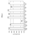
- the batteries according to Examples 2 and 5 and Comparative Example 1 were measured regarding coulombic efficiency during CV cycling. The measurement was performed at 25°C under a condition of 0.02mV/sec at 4.5V, 4.6V, and 4.8V, respectively. The results are provided in FIG. 4 .
- the battery cell of Comparative Example 1 had sharply decreased charge-discharge efficiency at a high voltage of 4.8V.
- the battery cells including ATP according to Examples 2 and 5 maintained charge-discharge efficiency at a high voltage.
- the battery cell of Example 2 exhibited better charge-discharge efficiency than that of Example 5.
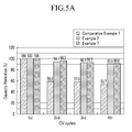
- the battery cells according to Examples 2 and 7 and Comparative Example 1 were measured regarding capacity retention depending on cycles. The measurement was performed at 25°C under a condition of 0.02mV/sec. The result is provided in FIG. 5A .
- the battery cell of Comparative Example 1 battery had sharply decreased capacity retention by 50% from the second cycle.
- the battery cells of Examples 2 and 7 maintained capacity retention of more than 90% regardless of CV times.
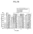
- the battery cells were measured regarding cycling efficiency under the same condition. The results are provided in FIG. 5B .
- the battery cell of Comparative Example 1 had sharply decreased efficiency at the 1 st cycle and better efficiency at repeated cycles, which was lower than the efficiency at the 1 st cycle of the battery cells according to Examples 2 and 7.
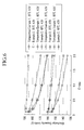
- the batteries according to Comparative Example 1 and Example 2 were selectively experimented.
- the experiment was performed changing a temperature of 25°C and 60°C and a charge cut-off voltage of 4.3V and 4.5V.
- the results are provided in FIG. 6 .
- the battery cell of Example 2 had high capacity under the same temperature and charge cut-off voltage at high C-rate.
- the battery cells had the biggest capacity difference at 60°C and 4.5V.
- the reason is that the battery cell including an electrode having ATP and the one including an electrode having no ATP had a bigger capacity difference at higher temperature and higher charge cut-off voltage.
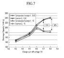
- Example 2 Two battery cells according to Example 2 and Comparative Example 1 were selected and experimented. They were compared regarding capacity depending on charge cut-off voltage and separately experimented at 0.5C and 1C. The results are provided in FIG. 7 .
- the battery cells according to Example 2 and Comparative Example 1 had a bigger capacity difference at a higher charge cut-off voltage.
- the ATP is said to secure stability constantly, maintaining the capacity of a rechargeable battery at a high charge cut-off voltage.
- the battery cells according to Example 2 and Comparative Example 1 had a bigger discharge capacity difference at more cycles and a much bigger discharge capacity difference at a high rate of 1C.
- the battery cells according to Example 2 and Comparative Example 1 had a bigger discharge capacity difference at more cycles and a much bigger discharge capacity difference at a high temperature 60°C.
- the battery cell of Example 2 in general had efficiency of more than 94%, while the one of Comparative Example 1 had efficiency of less than 87%.
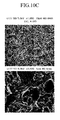
- FIGS. 10A , 10B , and 10C The surface of an electrode coated with a positive active material no ATP included in a battery cell according to Comparative Example 1 was examined depending on charge cut-off voltage. The results are provided in FIGS. 10A , 10B , and 10C .
- FIG. 10A shows a result under the conditions of 4.6V and 1C.
- FIG. 10B shows a result under the conditions of 4.7V and 1C.
- FIG. 10C shows a result under the conditions of 4.8V and 1C.
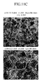
- FIGS. 11A , 11B , and 11C The surface of an electrode included in the battery cell according to Example 2 was examined depending on voltage. The results are provided in FIGS. 11A , 11B , and 11C .
- FIG. 11A provides a result under the conditions of 4.6V and 1C.
- FIG. 11B provides a result under the conditions of 4.7V and 1C.
- FIG. 11C provides a result under the conditions of 4.8V and 1C.
Landscapes
- Chemical & Material Sciences (AREA)
- Chemical Kinetics & Catalysis (AREA)
- Electrochemistry (AREA)
- General Chemical & Material Sciences (AREA)
- Composite Materials (AREA)
- Engineering & Computer Science (AREA)
- Materials Engineering (AREA)
- Crystallography & Structural Chemistry (AREA)
- Inorganic Chemistry (AREA)
- Battery Electrode And Active Subsutance (AREA)
- Secondary Cells (AREA)
- Inorganic Compounds Of Heavy Metals (AREA)
Abstract
[Chemical Formula 1] Li1+xM(I)M(II)2-xSiyP3-yO12,
wherein M(I) and M(II) are selected from the group consisting of Al, Zr, Hf, Ti, Ge, Sn, Cr, Nb, Ga, Fe, Sc, In, Y, La, Lu, and Mg, and 0<x≤0.7, 0≤y≤ 1.
Description
- Provided are a positive active material for a lithium secondary battery and a method of manufacturing the same.
- Electronic equipment has recently become down-sized and lighter as portable electronic devices have become more widely used. Accordingly, research is conducted on lithium secondary batteries with high energy density as power sources for portable electronic devices.
- A lithium secondary battery typically includes materials that reversibly intercalate or deintercalate lithium ions as negative and positive electrodes and also includes an organic electrolyte or a polymer electrolyte through which lithium ions move between the positive and negative electrodes. Electrical energy is produced through oxidation/reduction when lithium ions are intercalated/deintercalated at the positive and negative electrodes.
- A lithium metal has been typically used as the negative active material for such a lithium secondary battery. However, since the lithium metal can cause battery short-circuiting due to dendrites during charging and discharging, a lithium secondary battery may explode. In order to solve this problem, a carbon-based material that can reversibly accept or supply lithium ions, while maintain structural and electrical characteristic, and that has a similar half-cell potential to a lithium metal during the intercalation and deintercalation of lithium ions is widely used as a negative active material.
- On the other hand, a positive active material for a lithium secondary battery may include the chalcogenide compound of a metal that can intercalate/deintercalate lithium ions and practically, a composite metal oxide such as LiCoO2, LiMn2O4, LiNiO2, LiNi1-xCoxO2 (0<x<1), LiMnO2, and the like. Among these positive active materials, LiNiO2 has a large charge capacity but is hard to synthesize and has poor cycleability. Mn-based active materials such as LiMn2O4, LiMnO2, and the like are easy to synthesize and environment-friendly as well as cost relatively low but has small capacity. In addition, since LiCoO2 has electric conductivity ranging from 10-2 to 1 S/cm at room temperatures, high operating battery voltage, and excellent electrode characteristic, it is widely used. However, LiCoO2 has the problem of low stability during the high rate charge and discharge and cannot be efficiently operated at high temperature and voltages over 4.3V.
- In general, these composite metal oxides are prepared by mixing raw solid powders and firing the mixture in a solid-phase reaction method. For example, Japanese Patent Notification
Hei 8-153513 - When an active material prepared according to the above method is applied to a lithium secondary battery, it may have a side reaction with an electrolyte and thus, may not maintain the main characteristics of the lithium secondary battery at high voltages.
- The present invention provides a positive active material which can maintain main characteristics of a rechargeable battery even at a high voltage.
- The present invention further provides a lithium secondary battery including the positive active material.
- According to one embodiment of the present invention, a positive active material for a lithium secondary battery is provided that includes a core including a compound that can reversibly intercalate/deintercalate lithium; and a lithium ion conductive ceramic compound attached to the surface of the core and represented by the following Chemical Formula 1.
[Chemical Formula 1] Li1+xM(I)xM(II)2-xSiyP3-yO12
- In
Chemical Formula 1, M(I) and M(II) are selected from the group consisting of Al, Zr, Hf, Ti, Ge, Sn, Cr, Nb, Ga, Fe, Sc, In, Y, La, Lu, and Mg, and 0<x≤0.7, 0≤ y≤ 1. - In
Chemical Formula 1, M(I) may be Al and M(II) may be Ti. - The compound represented by Chemical Formula 1 may be attached to the core as discrete particles and/or a layer.
- The positive active material for a lithium secondary battery may include the core in an amount ranging from 96 wt% to 98.5 wt% and the compound represented by the above Chemical Formula 1 in an amount ranging from 1.5 wt% to 4 wt%.
- The core may be at least one composite oxide including a metal selected from cobalt, manganese, nickel, and a combination thereof, and lithium.
- According to another embodiment of the present invention, a positive electrode including the positive active material, a conductive material, and a binder is provided.
- According to another embodiment of the present invention, a lithium secondary battery including the aforementioned positive electrode is provided.
- According to another embodiment of the present invention, a method of manufacturing a positive active material for a lithium secondary battery is provided that includes (a) mixing a Li source, a M(I) source, a M(II) source, and a phosphate source to prepare a mixture; (b) preparing a compound represented by the following
Chemical Formula 1 by heating the mixture in the process (a); (c) admixing a core including a compound that may reversibly intercalate and deintercalate lithium to the compound represented by the Chemical Formula 1 in the process (b) to prepare a mixed product; and (d) heating the mixed product.
[Chemical Formula 1] Li1+xM(I)xM(II)2-xSiyP3-yO12
- In
Chemical Formula 1, M(I) and M(II) are selected from the group consisting of Al, Zr, Hf, Ti, Ge, Sn, Cr, Nb, Ga, Fe, Sc, In, Y, La, Lu, and Mg, and 0<x≤0.7, 0≤ y≤1. - In
Chemical Formula 1, M(I) may be Al and M(II) may be Ti. - The process (b) may include (b1) heating the mixture to form a compound represented by the above
Chemical Formula 1 in a first heating step; (b2) pulverizing the resulting compound obtained in the process (b1); and (b3) heating to crystallize the compound pulverized in the process (b2) in a second heating step. Herein, first heating step may be performed at a lower temperature than the second heating step. - In the process (c), the core may comprise a composite oxide including a metal selected from cobalt, manganese, nickel, and a combination, and lithium.
- According to further embodiment of the present invention, a positive electrode for a lithium secondary battery is provided that includes a positive active material prepared according to the aforementioned method, a conductive material, and a binder.
- According to further embodiment of the present invention a lithium secondary battery including the aforementioned positive electrode is provided.
- The positive active material is coated with a highly ion conductive ceramic compound on the surface and thus, does not directly contact an electrolyte and a side reaction under high temperature/high voltage conditions is suppressed. In addition, the positive active material has fast ion transferring reaction on the coated surface, improving the impedance and the efficiency of a battery.
-
-
FIG. 1 is a flowchart showing a method of manufacturing a positive active material for a rechargeable battery according to one embodiment of the present invention. -
FIGS. 2A and2B show discharge capacity experimental data depending on Li1+xM(I)xM(II)2-xSiyP3-yO12 content. -
FIGS. 3A and3B show cyclic voltammogram data. -
FIG. 4 shows CV efficiency data at the 1st cycle. -
FIG. 5A and5B show capacity retention and cyclic efficiency data depending on CV cycles. -
FIG. 6 shows temperature- and voltage-rate performance data. -
FIG. 7 is capacity comparison data depending on charge cut-off voltage. -
FIGS. 8A and8B show discharge capacity comparison data depending on cycle numbers at high charge cut-off voltage. -
FIG. 9 shows 1st cycle efficiency comparison data at a high charge cut-off voltage depending on various potentials and C-rates. -
FIGS. 10A ,10B , and10C provide SEM photographs of the surface of an electrode according to Comparative Example 1 at a high charge cut-off voltage. -
FIG. 11A ,11B , and11C provide SEM photographs of the surface of an electrode according to Example 2 at a high charge cut-off voltage. - This disclosure will be described more fully hereinafter with reference to the accompanying drawings, in which certain embodiments are shown.
- A positive active material for a lithium secondary battery may include a highly ion conductive ceramic compound to secure stability at a high voltage while not impairing characteristics of the lithium secondary battery.
- Accordingly, a battery including a positive active material for a lithium secondary battery has no performance deterioration at a voltage of 4.3V or less and reinforced battery characteristic at a voltage of 4.3V or more, or 4.3V to 4.7V.
- The positive active material for a lithium secondary battery includes a core including a compound that reversibly intercalates and deintercalates lithium ions, and a compound attached to the surface of the core as a highly ion conductive ceramic compound, represented by the following Chemical Formula 1:
[Chemical Formula 1] Li1+xM(I)xM(II)2-xSiyP3-yO12
- In
Chemical Formula 1, M(I) and M(II) are selected from the group consisting of Al, Zr, Hf, Ti, Ge, Sn, Cr, Nb, Ga, Fe, Sc, In, Y, La, Lu, and Mg, and 0<x≤0.7, 0 ≤ y≤1. - Examples of a compound used for the core particle include a common positive active material compound used for a positive electrode for a conventional electrochemical device, in particular, at least one composite oxide of a metal selected from cobalt, manganese, nickel, and a combination thereof, and lithium, and in more particular, one of the compounds listed by the following
Chemical Formula 2.
[Chemical Formula 2] LiaA1-bXbD2 (0.90 ≤ a ≤ 1.8, 0 ≤ b ≤ 0.5); LiaA1-bXbO2-cDc (0.90 ≤ a ≤ 1.8, 0 ≤ b ≤ 0.5, 0 ≤ c ≤0.05); LiαE2-bXbO4cDc (0.90 ≤ a ≤ 1.8, 0 ≤ b ≤ 0.5, 0 ≤ c ≤ 0.05); LiαNi1-b-cCobXcDα (0.90 ≤ a ≤ 1.8, 0 ≤ b ≤ 0.5, 0 ≤ c ≤ 0.05, 0 < α ≤ 2); LiaNi1-b-cCobXcO2-αTα (0.90 ≤ a ≤ 1.8, 0 ≤ b ≤ 0.5, 0 ≤ c ≤ 0.05, 0 < α < 2); LiaNi1-b-cCobXcO2-αT2 (0.90 ≤ a ≤ 1.8, 0 ≤ b ≤ 0.5, 0 ≤ c ≤ 0.05, 0 < α < 2); LiaNi1-b-cMnbXcDα (0.90 ≤ a ≤ 1.8, 0 ≤ b ≤ 0.5, 0 ≤ c ≤ 0.05, 0 < a ≤ 2); LiaNi1-b-cMnbXcO2-αTα(0.90 ≤ a ≤ 1.8, 0 ≤ b ≤ 0.5, 0 ≤ c ≤ 0.05, 0 < α < 2); LiaNi1-b-cMnbXcO2-αT2 (0.90 ≤ a ≤ 1.8, 0 ≤ b ≤ 0.5, 0 ≤ c ≤ 0.05, 0 < α < 2); LiaNibEcGdO2 (0.90 ≤ a ≤ 1.8, 0 ≤ b ≤ 0.9, 0 ≤ c ≤ 0.5, 0.001 ≤ d ≤ 0.1); LiaNibCocMndGeO2 (0.90 ≤ a ≤ 1.8, 0 ≤ b ≤ 0.9, 0 ≤ c ≤0.5, 0 ≤d ≤0.5, 0.001 ≤e ≤0.1); LiaNiGbO2 (0.90 ≤a ≤ 1.8, 0.001 ≤ b ≤ 0.1); LiaCoGbO2 (0.90 ≤ a ≤ 1.8, 0.001 ≤ b ≤ 0.1); LiaMnGbO2 (0.90 ≤ a ≤ 1.8, 0.001 ≤ b ≤ 0.1); LiaMn2GbO4 (0.90 ≤ a ≤ 1.8, 0.001 ≤ b ≤ 0.1); QO2; QS2; LiQS2; V2O5; LiV2O5; LiZO2; LiNiVO4; Li(3-f)J2(PO4)3 (0 ≤ f ≤ 2); Li(3-f)Fe2(PO4)3 (0 ≤ f ≤ 2); and LiFePO4
- In
Chemical Formula 2, A is selected from the group consisting of Ni, Co, Mn, and a combination thereof; X is selected from the group consisting of Al, Ni, Co, Mn, Cr, Fe, Mg, Sr, V, a rare earth element, and a combination thereof; D is selected from the group consisting of O, F, S, P, and a combination thereof; E is selected from the group consisting of Co, Mn, and a combination thereof; T is selected from the group consisting of F, S, P, and a combination thereof; G is selected from the group consisting of Al, Cr, Mn, Fe, Mg, La, Ce, Sr, V, and a combination thereof; Q is selected from the group consisting of Ti, Mo, Mn, and a combination thereof; Z is selected from the group consisting of Cr, V, Fe, Sc, Y, and a combination thereof; and J is selected from the group consisting of V, Cr, Mn, Co, Ni, Cu, and a combination thereof. - The highly ion conductive ceramic compound (e.g., Li1+xM(I)xM(II)2-xSiyP3-yO12,) represented by
Chemical Formula 1 has excellent lithium conductivity and electronic conductivity is negligible. - In
Chemical Formula 1, M(I) and M(II) are selected from the group consisting of Al, Zr, Hf, Ti, Ge, Sn, Cr, Nb, Ga, Fe, Sc, In, Y, La, Lu, Mg. The ceramic compound may have different conductivity depending on a material added thereto. InChemical Formula 1, M(I) may be Al and M(II) may be Ti. - When the highly ion conductive ceramic compound represented by the above
Chemical Formula 1 is attached to the surface of the core, it suppresses a side reaction that may occur between the core and the electrolyte of a lithium secondary battery. - Herein, the x and y may be in a range of 0<x≤0.7 and 0≤ y≤ 1 as aforementioned. When the x and y are within the range, the positive active material has optimal electrochemical effects.
- Conventionally, a core has been coated with an oxide, hydroxide, oxyhydroxide, oxycarbonate, or hydroxycarbonate of an element such as Al, Ti, Mg, Sn, or the like. However, the highly lithium ion conductive ceramic compounds according to the present invention brings about stability of a lithium secondary battery at a high voltage when coated on the surface of a core, rather than the coating of the compound.
- The highly lithium ion conductive ceramic compounds represented by the above
Chemical Formula 1 may be attached to the core as a layer and/or as discrete particles. The discrete particle attachment indicates that ceramic compound particles discontinuously and randomly exist on the surface of the core. - When the highly lithium ion conductive ceramic compounds is attached to the surface of the core as a layer, the layer may be 0.05 to 5 µm thick. When the coating layer is thicker than this range, less active material may be coated per unit volume of an electrode, deteriorating the energy density and electrochemical performance of a lithium ion battery. In addition, the active material may have decreased electronic conductivity, deteriorating battery performance. When the coating layer is thin, it may have little effect on suppressing side reactions between the core and the electrolyte.
- When the highly lithium ion conductive ceramic compound is attached to the core as discrete particles, the highly lithium ion conductive ceramic particle may have a size ranging from 0.05 to 4 µm. When the highly lithium ion conductive ceramic particle has a size within the range, the highly lithium ion conductive ceramic compounds may surround the core with appropriate density, not limiting the effects of the present invention.
- The aforementioned positive active material for a lithium secondary battery may include the core particle in an amount ranging from 96 wt% to 98.5 wt% and the highly lithium ion conductive ceramic compound ranging from 1.5 wt% to 4 wt%. In addition, the core particle may be included in an amount ranging from 97 wt% to 98 wt%, and the highly lithium ion conductive ceramic compound may be in an amount ranging from 2 wt% to 3 wt%. When the highly lithium ion conductive ceramic compound and the core are included within the range, a lithium secondary battery including the active material may have maximum discharge capacity.
- This positive active material according to the present invention includes a highly ion conductive ceramic compound for coating and thus, may be prevented from directly contacting an electrolyte and inhibit a side reaction between the core and the electrolyte at high temperatures or high voltages. Accordingly, the positive active material enhances the stability of a battery system without using an expensive additive.
- Furthermore, a lithium secondary battery including a positive active material has excellent high rate characteristics and high battery efficiency.
- Hereinafter, illustrated is a method of manufacturing a positive active material for a rechargeable battery.
-
FIG. 1 provides a flowchart showing a method of manufacturing a positive active material for a rechargeable battery. - In order to prepare the highly lithium ion conductive ceramic particle, a method of manufacturing a positive active material for a rechargeable battery according to one embodiment of the present invention includes mixing a Li source, a M(I) source, a M(II) source, and a phosphate source (S101). In the mixing, a Si source may be further added.
- As aforementioned, since the highly lithium ion conductive ceramic particle may include each element in various amounts, the sources may be included corresponding therewith.
- The Li source may include, for example, Li2CO3, LiNO3, Li3PO4, and the like. Examples of M(I) source may include, but is not limited into oxide, phosphate, nitrate, alkoxide of M(I), and the like. If M(I) is Al, examples of the Al source may include Al2O3, A1PO4, Al(NO3)3 · 9H2O, and the like. Examples of M(I) source may include, but is not limited into oxide, phosphate, nitrate, alkoxide of M(II), and the like. If M(II) is Ti, example of the Ti source may include TiO2, TiP2O7 titanium propoxide, titanium butoxide and the like. Examples of the phosphate source may include (NH4)2HPO4 NH4H2PO4, Li3PO4, and the like. Examples of the Si source may include, but is not limited into oxide, alkoxide, hydroxide of Si.
- The mixing may be performed through ball-milling. The ball-milling may be performed using a ball, for example, a zirconia ball and the like. The ball may have a size ranging from about 0.3 to about 10 mm. The ball may vary unless it limits the effects of the present invention. The ball-milling may be performed for about 1 to about 48 hours. When the ball-milling is performed within the above time, the highly ion conductive ceramic compound may be prepared to have a desirable size for attachment to a core.
- However, the mixing may be performed in various ways other than the ball-milling, if reactants may be uniformly mixed.
- Next, the mixture may be heated in a first heating step (S 102). The mixture prepared in the process S101 may be formed into the highly ion conductive ceramic compound through the first heating step S 102.
- The firstly heating step S102 may be performed by increasing a temperature at an increasing rate ranging from 0.1 to 10 °C/min. When the increasing rate is within the range, a side reaction may be suppressed.
- The heating may be performed up to a temperature ranging from 650°C to 800°C. When the first heating step S102 is performed over 800°C, there may be a side reaction problem.
- Then, the highly ion conductive ceramic compound may be naturally cooled down. Next, the cooled highly ion conductive ceramic compound may be ground (S 103).
- Herein, the highly ion conductive ceramic compound may be uniformly ground into a size ranging from 0.05µm to 4µm. This pulverizing may include any method if the highly ion conductive ceramic compound is pulverized into particles with a uniform size. For example, the pulverizing may include a paint shaker, a homogenizer, a PD mixer, a ball-miller, and the like.
- The ball milling may be performed using a ball, for example, a zirconia ball and the like. The ball may have a size ranging from about 0.3 mm to about 5 mm. The size or shape of the ball has no particular limit unless it limits effects of the present invention. The ball milling may be performed for about 1 hour to about 48 hours. When the ball milling is performed within the time, the highly ion conductive ceramic compound particles may be uniformly distributed.
- Then, the resultant may be heated in a second heating step (S 104).
- The second heating step S 104 may be performed by increasing a temperature at an increasing rate ranging from about 0.5°C/min to about 10°C/min. When the heating is performed within the range, a reaction may be suppressed. The positive active material may have uniform crystallinity since it has no temperature gradient overall.
- The second heating step may be performed at a higher temperature than the first heating step S102 and may be higher than or equal to about 800°C and in particular, higher than or equal to about 950°C. When the second heating step is lower than the temperature, highly ion conductive ceramic particles may have low structural crystallinity, deteriorating ion conductivity and having bad influence on battery performance.
- The second heating step (S104) may transform a highly ion conductive ceramic compound from a mixture of different crystalline phases to one-phase crystalline structure.
- Next, the prepared highly ion conductive ceramic compound may be cooled down to about 300°C at a descending rate ranging from about 1°C/min to 5°C/min and then, naturally cooled down. When the highly ion conductive ceramic compound is cooled down faster than the range, it may have inside and surface structure transformation, leading to insufficient performance of an active material.
- The second heating step (S104) can provide crystalline highly ion conductive ceramic compound. The crystalline highly ion conductive ceramic compound may be ground again (S105).
- The pulverizing (S105) may be performed under hygroscopic condition. Herein, the highly ion conductive ceramic compound may be ground to be finer. The pulverizing may have no particular limit if it may provide uniform pulverizing and mixing and for example, include ball milling, a paint shaker, or a homogenizer.
- For example, the pulverizing (S105) may be performed by ball-milling. The ball milling may be performed under a solvent. The solvent may include ethanol, hexane, heptane, isopropanol, N-methyl pyrrolidone, and the like.
- The ball milling may be performed using a ball, for example, a zirconia ball, and the like. The ball may have a size ranging from about 0.3 mm to about 10 mm. The ball has no limit in its size or shape. The ball milling may be performed for about 8 hours to about 48 hours. When the ball milling is performed within the time range, it may uniformly distribute highly ion conductive ceramic compound particles.
- When pulverizing under a solvent, the highly ion conductive ceramic compound is precipitated (S106). The precipitation may be performed for about 6 hours to about 8 hours (S106). This time range may be sufficient for the precipitation.
- Then, the precipitated highly ion conductive ceramic compound is collected from the top, and a core including a compound that may reversibly intercalate and deintercalate lithium may be added thereto (S107).
- The added core may include at least one composite oxide including a metal selected from cobalt, manganese, nickel, and a combination thereof, and lithium.
- Next, the mixture is mixed to attach the highly ion conductive ceramic compound to the surface of the core particle (S108).
- The mixing may include any method if it brings about uniform mixture but does not change particle diameter.
- For example, it may be performed by ball milling. The ball milling is performed using a ball, for example, a zirconia ball and the like. The ball has a size ranging from about 0.3 mm to 10 mm.
- The ball has no limit in its size and shape unless it limits effects of the present invention. When the ball has a size only within the range, highly ion conductive ceramic compound may be attached to a core as discrete particles and/or a layer. The ball milling may be performed for about 1 hour to about 48 hours. When the ball milling is performed within the time range, ATP may be sufficiently attached to a core particle.
- In this way, a positive active material for a lithium secondary battery is prepared, the positive active material including a core that includes a compound that may reversibly intercalate and deintercalate lithium with highly ion conductive ceramic compound attached to the surface thereof, according to one embodiment of the present invention.
- When the mixing (S108) is performed in a ball milling method, highly ion conductive ceramic compound particles may be uniformly attached to the surface of core particles. In addition, methods according to embodiments of the invention have low costs.
- Then, a third heating step (S 109) may be performed to complete the reaction.
- The third heating step (S109) may be performed by increasing the temperature at an increasing rate ranging from about 0.5°C/min to about 10°C/min. When the heating is performed within the increasing rate, the reaction may be controlled.
- The heating may be performed until the temperature reaches a temperature ranging from about 650°C to about 950°C. When the heating is performed within this range, it may stabilize core particles attached with highly ion conductive ceramic compound particles to the surface.
- Then, the core attached with highly ion conductive ceramic compound to the surface is cooled down to about 300°C at a descending rate ranging from about 1°C/min to about 2°C/min and naturally cooled down.
- According to another embodiment of the present invention, a positive electrode for a lithium secondary battery is provided by mixing the aforementioned positive active material, a conductive material, and a binder in a solvent to prepare an active material composition, and coating the active material composition on a current collector. The solvent may include N-methylpyrrolidone and the like but is not limited thereto.
- A negative electrode, an electrolyte, and a separator for fabricating a battery are well-known in a related art and will not be illustrated in detail here.
- According to another embodiment of the present invention, a lithium secondary battery is fabricated by using the positive electrode, a negative electrode, an electrolyte, and a separator.
- The following examples illustrate embodiments of the present invention in more detail. However, it is understood that the present invention is not limited by these examples.
- Li1.3Al0.3Ti1.7(PO4)3 (ATP) was prepared in the following method.
- In order to synthesize 10g of ATP, 1.25g of Li2CO3 having 99% of purity and having 40 mesh (Sigma-Aldrich Co), 3.54g of TiO2 having 99% of purity and 325 µm, 0.399g of Al2O3 having 150 mesh and in an activated neutral standard level (Sigma-Aldrich Co.), and 10.33g of (NH4)2HPO4 in the first grade (Shinyo Pure Chemical Co., Ltd.) were ball-milled for 2 to 12 hours with a 5mm zirconia ball.
- Then, the mixture was heated by increasing a temperature at an increasing rate of 1°C/min from a room temperature to 700°C, maintained at 700°C for 2 hours, and then, naturally cooled down.
- The cooled product was ball-milled using a 5mm zirconia ball for 12 to 24 hours.
- The ball milled product was heated by increasing a temperature at an increasing
rate 1 °C/min to 920°C and maintained at 920°C for 8 hours and then, cooled down at a descending rate of 1°C/min down to 300°C and naturally cooled down. - The resulting Li1.3Al0.3Ti1.7(PO4)3 by twice-heating was ball-milled in ethanol for 48 to 72 hours using a 5mm zirconia ball.
- The ball-milled ATP was precipitated in ethanol for 7 hours. Then, LiCoO2 was added to the precipitated ATP. The ATP and the LiCoO2 were ball-milled in ethanol for 1 to 10 hours using a 5mm zirconia ball.
- The ball-milled product was heated by increasing the temperature at an increasing rate of 1°C/min up to 700°C and maintained at 700°C for 2.5 hours and then, cooled down at a rate of 1°C/min down to 300°C and naturally cooled down, preparing LiCoO2 coated with ATP on the surface.
- Example 1: LiCoO2 including ATP particles attached to the surface was used as a positive active material. The ATP particle was attached to LiCoO2 as a thin layer and as discrete particles. The positive active material had a size of 20µm and included 1 wt% of ATP based on its total weight.
- 94 wt% of the LiCoO2 positive active material coated with ATP, 3 wt% of carbon black as a conductive agent, and 3wt% of polyvinylidene fluoride as a binder were added to N-
methyl 2 pyrrolidone (NMP) as a solvent, preparing positive active material slurry. The positive active material slurry was coated on a 15 µm-thick aluminum (Al) thin film as a positive current collector and then, dried and roll-pressed, fabricating a positive electrode. - Example 2: LiCoO2 including ATP particles attached to the surface was used as a positive active material. The ATP particle was attached to LiCoO2 as a thin layer and as discrete particles. The positive active material had a size of 20 µm and included 2 wt% of ATP based on its entire weight.
- 94 wt% of the LiCoO2 positive active material coated with ATP, 3 wt% of carbon black as a conductive agent, and 3 wt% of polyvinylidene fluoride as a binder were added to N-
methyl 2 pyrrolidone (NMP) as a solvent, preparing positive electrode slurry. The positive electrode slurry was coated on a 15 µm-thick aluminum (Al) thin film as a current collector and then, dried and roll-pressed, fabricating a positive electrode. - Example 3: LiCoO2 coated with ATP particles on the surface was used as a positive active material. The ATP particle was attached to LiCoO2 as a thin layer and as discrete particles. The positive active material had a size of 20 µm and included 3 wt% of ATP based on its entire weight.
- 94 wt% of the ATP-coated LiCoO2 positive active material, 3 wt% of carbon black as a conductive agent, and 3 wt% of polyvinylidene fluoride as a binder were added to N-
methyl 2 pyrrolidone (NMP) as a solvent, preparing positive active material slurry. The positive active material slurry was a 15 µm-thick aluminum (Al) thin film as a current collector and then, dried and roll-pressed, fabricating a positive electrode. - Example 4: LiCoO2 coated with ATP particles was used as a positive active material. The ATP particle was attached to LiCoO2 as a thin layer and as discrete particles. The positive active material had a size of 20 µm and included 5 wt% of ATP based on the entire weight.
- 94 wt% of the ATP-coated LiCoO2 positive active material, 3 wt% of carbon black as a conductive agent, and 3 wt% of polyvinylidene fluoride as a binder were added to N-
methyl 2 pyrrolidone (NMP) as a solvent, preparing positive electrode slurry. The positive electrode slurry was coated on a 15 µm-thick aluminum (Al) thin film current collector and then, dried and roll-pressed, fabricating a positive electrode. - Example 5: LiCoO2 coated with ATP particles was used as a positive active material. The ATP particle was attached to LiCoO2 as a thin layer and as discrete particles. The positive active material had a size of 20 µm and included 9 wt% of ATP based on the entire weight.
- 94 wt% of the ATP-coated LCO positive active material, 3 wt% of carbon black as a conductive agent, and 3 wt% of polyvinyldene fluoride as a binder were added to N-
methyl 2 pyrrolidone (NMP) as a solvent, preparing positive active material slurry. The positive active material slurry was coated on a 15 µm-thick aluminum (Al) thin film as a current collector and then, dried and roll-pressed, fabricating a positive electrode. - Comparative Example 1: LiCoO2 coated with no ATP particles was used as a positive active material. The positive active material had a size of 20 µm.
- 94 wt% of the LiCoO2 positive active material, 3 wt% of carbon black as a conductive agent, and 3 wt% of polyvinylidene fluoride as a binder were added to N-
methyl 2 pyrrolidone (NMP) as a solvent, preparing positive active material slurry. The positive active material slurry was coated on a 15 µm-thick aluminum (Al) thin film as a current collector and then, dried and roll-pressed, fabricating a positive electrode. - Example 6: LiCoO2 coated with ATP particles on the surface was used as a positive active material. The ATP particle was attached to LiCoO2 as a thin layer and as discrete particles. The positive active material had a size of 10 µm and included 2 wt% of ATP based on the entire weight.
- 94 wt% of the ATP-coated LiCoO2 positive active material, 3 wt% of carbon black as a conductive agent, and 3 wt% of polyvinylidene fluoride as a binder were added to N-
methyl 2 pyrrolidone (NMP) as a solvent, preparing positive active material slurry. The positive active material slurry was coated on a 15 µm-thick aluminum (Al) thin film as a current collector and then, dried and roll-press, preparing a positive electrode. - Example 7: LiCoO2 coated with ATP particles on the surface was used as a positive active material. The ATP particle was attached to LiCoO2 as a thin layer and as discrete particles. The positive active material had a size of 10 µm and included 3 wt% of ATP based on the entire weight.
- 94 wt% of the ATP-coated LiCoO2 positive active material, 3 wt% of carbon black as a conductive agent, and 3 wt% of polyvinylidene fluoride as a binder were added to N-
methyl 2 pyrrolidone (NMP) as a solvent, preparing positive active material slurry. The positive active material slurry was coated on a 15µm-thick aluminum (Al) thin film as a current collector and then, dried and roll-pressed, fabricating a positive electrode. - Example 8: LiCoO2 coated with ATP particles on the surface was used as a positive active material. The ATP particle was attached to LiCoO2 as a thin layer and as discrete particles. The positive active material had a size of 10 µm and included 5 wt% of ATP based on the entire weight.
- 94 wt% of the ATP-coated LiCoO2 positive active material, 3 wt% of carbon black as a conductive agent, and 3 wt% of polyvinylidene fluoride as a binder were added to N-
methyl 2 pyrrolidone (NMP) as a solvent, preparing positive electrode slurry. The positive electrode slurry was coated on a 15 µm-thick aluminum (Al) thin film as a current collector and then, dried and roll-pressed, preparing a positive electrode. - Comparative Example 2: LiCoO2 coated with no ATP particles on the surface was used as a positive active material. The positive active material had a size of 10 µm.
- 94 wt% of the LCO positive active material, 3 wt% of carbon black as a conductive agent, and 3 wt% of polyvinylidene fluoride as a binder were added to N-
methyl 2 pyrrolidone (NMP) preparing positive active material slurry. The positive active material slurry was coated on a 15 µm-thick aluminum (Al) thin film as a current collector and then, dried and roll-pressed, fabricating a positive electrode. - Each prepared positive electrode was used with a Li metal as a counter electrode and an electrolyte prepared by mixing ethylene carbonate, ethylmethyl carbonate, and diethyl carbonate in a volume ratio of 3:6:1 1 and including 1.15M of LiPF6 in the mixture to fabricate a half-cell type.
- The battery cells according to Examples 1 to 8 and Comparative Examples 1 and 2 were measured regarding discharge capacity. The results are provided in
FIGS. 2A and2B . - Referring to
FIG. 2A , the battery cells were discharged at C-rates ranging from 0.1C to 2C, all similar tendencies exhibited. However, the battery cell according to Example 3 exhibited small capacity drop at high rates, but that according to Comparative Example 1 exhibited large capacity drop at high rates. - Referring to
FIG. 2B , the battery cells had a bigger discharge capacity difference at a higher rate. The batteries of Comparative Example 2 and Example 7 had the biggest discharge capacity difference at 2C. - In addition, the battery cells including a positive active material with a smaller particle size and including more ATP had smaller discharge capacity difference.
- Referring to
FIGS. 2A and2B , LiCoO2 coated with ATP in an amount ranging from 1.5 to 3.5 wt% turned out to accomplish excellent battery discharge capacity. - The battery cells according to Comparative Example 1 and Example 2 were used at a scanning rate of 0.02mV/sec at a temperature of 25°C.
- The results are provided in
FIGS. 3A and3B . As shown inFIG. 3A and3B , the battery cells of Examples 2 and 3 had a big current at a higher voltage (right at the X axis in the graph) and thus, excellent stability at a high voltage. - The batteries according to Examples 2 and 5 and Comparative Example 1 were measured regarding coulombic efficiency during CV cycling. The measurement was performed at 25°C under a condition of 0.02mV/sec at 4.5V, 4.6V, and 4.8V, respectively. The results are provided in
FIG. 4 . - Referring to
FIG. 4 , the battery cell of Comparative Example 1 had sharply decreased charge-discharge efficiency at a high voltage of 4.8V. To the contrary, the battery cells including ATP according to Examples 2 and 5 maintained charge-discharge efficiency at a high voltage. Furthermore, the battery cell of Example 2 exhibited better charge-discharge efficiency than that of Example 5. - The battery cells according to Examples 2 and 7 and Comparative Example 1 were measured regarding capacity retention depending on cycles. The measurement was performed at 25°C under a condition of 0.02mV/sec. The result is provided in
FIG. 5A . - As shown in
FIG. 5A , the battery cell of Comparative Example 1 battery had sharply decreased capacity retention by 50% from the second cycle. The battery cells of Examples 2 and 7 maintained capacity retention of more than 90% regardless of CV times. - The battery cells were measured regarding cycling efficiency under the same condition. The results are provided in
FIG. 5B . - As shown in
FIG. 5B , the battery cell of Comparative Example 1 had sharply decreased efficiency at the 1st cycle and better efficiency at repeated cycles, which was lower than the efficiency at the 1st cycle of the battery cells according to Examples 2 and 7. - The batteries according to Comparative Example 1 and Example 2 were selectively experimented. The experiment was performed changing a temperature of 25°C and 60°C and a charge cut-off voltage of 4.3V and 4.5V. The results are provided in
FIG. 6 . - As shown in
FIG. 6 , the battery cell of Example 2 had high capacity under the same temperature and charge cut-off voltage at high C-rate. - In addition, the battery cells had the biggest capacity difference at 60°C and 4.5V. The reason is that the battery cell including an electrode having ATP and the one including an electrode having no ATP had a bigger capacity difference at higher temperature and higher charge cut-off voltage.
- Two battery cells according to Example 2 and Comparative Example 1 were selected and experimented. They were compared regarding capacity depending on charge cut-off voltage and separately experimented at 0.5C and 1C. The results are provided in
FIG. 7 . - As shown in
FIG. 7 , the battery cells according to Example 2 and Comparative Example 1 had a bigger capacity difference at a higher charge cut-off voltage. In other words, the ATP is said to secure stability constantly, maintaining the capacity of a rechargeable battery at a high charge cut-off voltage. - On the contrary, the battery cell of Comparative Example 1 had a decrease in capacity at 4.7V and 4.8V, which shows that a battery cannot work.
- Two battery cells according to Comparative Example 1 and Example 2 were selected and experimented. The battery cells were experimented at a high charge cut-off voltage of 4.5V or more and respectively twice experimented. The discharge capacity results at a high charge cut-off voltage depending on cyclings are provided in
FIGS. 8A and8B . - Referring to
FIG. 8A , the battery cells according to Example 2 and Comparative Example 1 had a bigger discharge capacity difference at more cycles and a much bigger discharge capacity difference at a high rate of 1C. - Referring to
FIG. 8B , the battery cells according to Example 2 and Comparative Example 1 had a bigger discharge capacity difference at more cycles and a much bigger discharge capacity difference at ahigh temperature 60°C. - Two battery cells according to Comparative Example 1 and Example 2 were selected and experimented. The first cycling efficiency experiment was performed at a high charge cut-off voltage of 4.5V or more at a rate of 0.5C and 1C. The results are provided in
FIG. 9 . - The battery cell of Example 2 in general had efficiency of more than 94%, while the one of Comparative Example 1 had efficiency of less than 87%.
- The surface of an electrode coated with a positive active material no ATP included in a battery cell according to Comparative Example 1 was examined depending on charge cut-off voltage. The results are provided in
FIGS. 10A ,10B , and10C .FIG. 10A shows a result under the conditions of 4.6V and 1C.FIG. 10B shows a result under the conditions of 4.7V and 1C.FIG. 10C shows a result under the conditions of 4.8V and 1C. - As shown in
FIG. 10A ,10B , and10C , lots of side reactions were examined on the surface of an electrode at a high charge cut-off voltage of more than 4.6V. The side reaction tended to be severe at a higher charge cut-off voltage (at 4.7V and 4.8V). - The surface of an electrode included in the battery cell according to Example 2 was examined depending on voltage. The results are provided in
FIGS. 11A ,11B , and11C .FIG. 11A provides a result under the conditions of 4.6V and 1C.FIG. 11B provides a result under the conditions of 4.7V and 1C.FIG. 11C provides a result under the conditions of 4.8V and 1C. - As shown in
FIGS. 11A ,11B , and11C , there was no side reaction on the surface of an electrode at a high voltage of 4.8V.
Claims (10)
- A positive active material for a lithium secondary battery comprising:a core comprising a compound capable of reversibly intercalating and deintercalating lithium ions; anda lithium ion conductive ceramic compound attached to a surface of the core and represented by Chemical Formula 1:wherein M(I) and M(II) are selected from the group consisting of Al, Zr, Hf, Ti, Ge, Sn, Cr, Nb, Ga, Fe, Sc, In, Y, La, Lu, and Mg, and 0<x≤0.7, 0≤y≤ 1.
[Chemical Formula 1] Li1+xM(I)M(II)2-xSiyP3-yO12
- The positive active material of claim 1, wherein the M(I) is Al and the M(II) is Ti.
- The positive active material of claim 1, wherein the compound represented by Chemical Formula 1 is attached to the core as a layer and/or discrete particles.
- The positive active material of claim 1, wherein the compound represented by Chemical Formula 1 is Li1.3Al0.3Ti1.7(PO4)3.
- The positive active material of claim 1, wherein the core comprises an amount of 96 wt% to 98.5 wt% of the positive active material, and the compound represented by Chemical Formula 1 comprises an amount of 1.5 wt% to 4 wt% of the positive active material.
- The positive active material of claim 1, wherein the core comprises at least one composite oxide of lithium and a metal selected from the group consisting of cobalt, manganese, nickel, and a combination thereof.
- A positive electrode comprising the positive active material of any one of claims 1 through 6.
- A lithium secondary battery comprising the positive electrode of claim 7.
- A method of manufacturing a positive active material for a lithium secondary battery according to any one of claims 1 through 6, the method comprising:mixing a Li source, a M(I) source, a M(II) source, and a phosphate source to prepare a mixture;heating the mixture to prepare a compound represented by Chemical Formula 1:
[Chemical Formula 1] Li1+xM(I)xM(II)2-xSiyP3-yO12 wherein M(I) and M(II) are selected from the group consisting of Al, Zr, Hf, Ti, Ge, Sn, Cr, Nb, Ga, Fe, Sc, In, Y, La, Lu, and Mg, and 0<x≤0.7, 0≤ y≤ 1;
admixing a core comprising a material that reversibly intercalates and deintercalates lithium ions to the compound represented by Chemical Formula 1 to prepare a mixed product; andheating the mixed product. - The method of claim 9, wherein the heating the mixture comprises;
heating the mixture to form a compound represented by the above Chemical Formula 1 in a first heating step;
pulverizing the compound obtained in the first heating step; and heating the pulverized compound for crystallization in a second heating step, wherein the first heating step is performed at a lower temperature than the second heating step.
Applications Claiming Priority (1)
| Application Number | Priority Date | Filing Date | Title |
|---|---|---|---|
| KR1020100108353A KR101256641B1 (en) | 2010-11-02 | 2010-11-02 | Positive active material for lithium secondary battery and method for thereof |
Publications (2)
| Publication Number | Publication Date |
|---|---|
| EP2448046A1 true EP2448046A1 (en) | 2012-05-02 |
| EP2448046B1 EP2448046B1 (en) | 2016-08-10 |
Family
ID=44862836
Family Applications (1)
| Application Number | Title | Priority Date | Filing Date |
|---|---|---|---|
| EP11187375.8A Active EP2448046B1 (en) | 2010-11-02 | 2011-11-01 | Positive active material for lithium secondary battery and secondary battery comprising the same |
Country Status (5)
| Country | Link |
|---|---|
| US (2) | US20120104334A1 (en) |
| EP (1) | EP2448046B1 (en) |
| JP (1) | JP2012099482A (en) |
| KR (1) | KR101256641B1 (en) |
| CN (1) | CN102468486A (en) |
Cited By (4)
| Publication number | Priority date | Publication date | Assignee | Title |
|---|---|---|---|---|
| CN104600273A (en) * | 2013-10-30 | 2015-05-06 | 北京有色金属研究总院 | Phosphorus-containing lithium ion battery anode material and preparation method thereof |
| EP2804845A4 (en) * | 2012-01-16 | 2015-08-19 | Ceramatec Inc | Lithium-ion-conducting materials |
| EP2985823A1 (en) * | 2014-08-11 | 2016-02-17 | Samsung SDI Co., Ltd. | Positive active material for rechargeable lithium battery, method of preparing same, and rechargeable lithium battery including same |
| EP2985819A1 (en) * | 2014-08-13 | 2016-02-17 | Samsung SDI Co., Ltd. | Positive active material for rechargeable lithium battery |
Families Citing this family (30)
| Publication number | Priority date | Publication date | Assignee | Title |
|---|---|---|---|---|
| KR101437886B1 (en) * | 2012-10-05 | 2014-09-05 | 한국과학기술연구원 | Nanocomposite cathod active material for lithium secondary batteries, method for preparing the same and lithium secondary batteries comprising the same |
| US9478783B2 (en) * | 2012-12-05 | 2016-10-25 | Samsung Sdi Co., Ltd. | Rechargeable lithium battery and a method of making a rechargeable lithium battery |
| WO2014181784A1 (en) * | 2013-05-07 | 2014-11-13 | Dowaホールディングス株式会社 | Positive-electrode active-material powder and manufacturing method therefor |
| CN103500810B (en) * | 2013-09-18 | 2016-05-25 | 宁波大学 | A kind of carbon solid acid borate doping phosphoric acid titanium lithium three component surface modification ferric fluoride anode material and preparation methods |
| CN103500818B (en) * | 2013-09-18 | 2016-05-11 | 宁波大学 | The two component surface modification ferric fluoride anode materials of a kind of Aluminate doping phosphoric acid titanium lithium and preparation method |
| CN103500834B (en) * | 2013-09-18 | 2016-05-11 | 宁波大学 | The two component surface modification ferric fluoride anode materials of a kind of borate doping phosphoric acid titanium lithium and preparation method |
| CN103490048B (en) * | 2013-09-18 | 2016-05-11 | 宁波大学 | The two component surface modification ferric fluoride anode materials of a kind of titanate esters doping phosphoric acid titanium lithium and preparation method |
| CN103490068B (en) * | 2013-09-18 | 2016-05-25 | 宁波大学 | A kind of carboxyl carbon titanate esters doping phosphoric acid titanium lithium three component surface modification ferric fluoride anode material and preparation methods |
| CN103500816B (en) * | 2013-09-18 | 2016-07-06 | 宁波大学 | A kind of carbon solid acid silane doping phosphoric acid titanium lithium three component surface modification ferric fluoride anode material and preparation method |
| CN104810545B (en) * | 2014-01-24 | 2017-08-11 | 江西赣锋电池科技有限公司 | Phosphate lithium fast-ionic conductor material and preparation method thereof |
| KR102228749B1 (en) * | 2014-08-11 | 2021-03-16 | 삼성에스디아이 주식회사 | Positive active material for rechargeable lithium battery, method of preparing the same, and rechargeable lithium battery including the same |
| WO2016159941A1 (en) * | 2015-03-27 | 2016-10-06 | A123 Systems, LLC | Surface modification of electrode materials |
| KR101840541B1 (en) | 2015-04-30 | 2018-03-20 | 주식회사 엘지화학 | Positive electrode material for lithium secondary battery, method for preparing the same and secondary battery comprising the same |
| KR102425828B1 (en) | 2015-06-02 | 2022-07-27 | 삼성에스디아이 주식회사 | Positive active material, positive electrode and lithium battery containing the material, method of manufacturing the material |
| WO2017002057A1 (en) | 2015-07-02 | 2017-01-05 | Umicore | Cobalt-based lithium metal oxide cathode material |
| KR101940149B1 (en) * | 2015-07-03 | 2019-01-18 | 주식회사 엘지화학 | Secondary battery and manufacturing method of thereof |
| KR102670558B1 (en) | 2016-03-15 | 2024-05-28 | 삼성에스디아이 주식회사 | Positive active material for rechargeable lithium battery and rechargeable lithium battery including same |
| KR102313090B1 (en) * | 2017-07-10 | 2021-10-18 | 주식회사 엘지에너지솔루션 | Positive electrode for secondary battery, method for preparing the same, and lithium secondary battery comprising the same |
| CN107768632A (en) * | 2017-10-16 | 2018-03-06 | 桑顿新能源科技有限公司 | A kind of LATP monocrystalline high-voltage anode material and preparation method thereof |
| CN107799746A (en) * | 2017-10-20 | 2018-03-13 | 西藏容汇锂业科技有限公司 | A kind of preparation method of modification of lithium ion battery anode material |
| CN108075122A (en) * | 2017-12-14 | 2018-05-25 | 电子科技大学 | A kind of preparation method of lithium ion battery composite cathode material |
| CN109461894B (en) * | 2017-12-29 | 2020-04-07 | 北京当升材料科技股份有限公司 | Positive electrode composite material for solid-state lithium ion battery and preparation method thereof |
| CN110858643B (en) * | 2018-08-24 | 2021-09-14 | 湖南杉杉新能源有限公司 | Fast ion conductor modified lithium ion battery cathode material and preparation method thereof |
| JP7209858B2 (en) * | 2019-02-20 | 2023-01-20 | ユミコア | Powdered Solid Electrolyte Compounds for Solid State Rechargeable Lithium-ion Batteries |
| CN110112383A (en) * | 2019-04-17 | 2019-08-09 | 湖北锂诺新能源科技有限公司 | The nickelic tertiary cathode material and preparation method thereof of titanium phosphate aluminium lithium cladding |
| CN111180703B (en) * | 2020-01-06 | 2023-04-11 | 西安理工大学 | Application of lithium aluminum titanium phosphate to lithium ion battery anode material and preparation method |
| CN112786891A (en) * | 2021-01-29 | 2021-05-11 | 东莞维科电池有限公司 | Electrode material, electrode plate, preparation method of electrode plate and lithium ion battery |
| JP7581084B2 (en) * | 2021-03-02 | 2024-11-12 | 株式会社東芝 | Active material, electrode, secondary battery, battery pack and vehicle |
| CN114388880B (en) * | 2022-01-19 | 2024-12-31 | 溧阳天目先导电池材料科技有限公司 | A NASICON structure lithium ion solid electrolyte material and its preparation method and application |
| CN117174996B (en) * | 2023-11-02 | 2024-03-05 | 合肥国轩高科动力能源有限公司 | Modified lithium titanium aluminum phosphate, its preparation method and lithium ion solid-state battery |
Citations (3)
| Publication number | Priority date | Publication date | Assignee | Title |
|---|---|---|---|---|
| JPH08153513A (en) | 1994-11-29 | 1996-06-11 | Sony Corp | Manufacture of positive electrode active material |
| JP2008226463A (en) * | 2007-03-08 | 2008-09-25 | Toyota Motor Corp | Lithium secondary battery, method for producing positive electrode active material coating particles, and method for producing lithium secondary battery |
| US20080241698A1 (en) * | 2006-10-31 | 2008-10-02 | Ohara Inc. | Lithium secondary battery and electrode for use in lithium secondary battery |
Family Cites Families (17)
| Publication number | Priority date | Publication date | Assignee | Title |
|---|---|---|---|---|
| JPH02162605A (en) | 1988-12-14 | 1990-06-22 | Japan Synthetic Rubber Co Ltd | Lithium ion conductive solid electrolyte and its manufacturing method |
| JPH02225310A (en) | 1989-02-23 | 1990-09-07 | Matsushita Electric Ind Co Ltd | Solid electrolyte and its manufacturing method |
| JP4029266B2 (en) * | 2001-12-04 | 2008-01-09 | 株式会社ジーエス・ユアサコーポレーション | Nonaqueous electrolyte battery and method for producing nonaqueous electrolyte battery |
| CN100568613C (en) * | 2004-02-06 | 2009-12-09 | 波利普拉斯电池有限公司 | Protected active metal electrode and battery cell structure with non-aqueous interlayer architecture |
| US7282295B2 (en) | 2004-02-06 | 2007-10-16 | Polyplus Battery Company | Protected active metal electrode and battery cell structures with non-aqueous interlayer architecture |
| US8592090B2 (en) * | 2004-08-18 | 2013-11-26 | Central Research Institute Of Electric Power Industry | Solid polymer electrolyte battery and method for manufacturing positive electrode sheet used therein |
| KR100701244B1 (en) * | 2004-11-16 | 2007-04-06 | 한국전기연구원 | Manufacturing method of lithium transition metal phosphate positive electrode active material coated with carbon for lithium secondary battery |
| US20070259271A1 (en) | 2004-12-13 | 2007-11-08 | Tetsuo Nanno | Laminate Including Active Material Layer and Solid Electrolyte Layer, and All Solid Lithium Secondary Battery Using the Same |
| KR100821102B1 (en) * | 2005-12-06 | 2008-04-08 | 주식회사 엘지화학 | Electrode with enhanced safety and electrochemical device having same |
| KR100791791B1 (en) | 2006-03-10 | 2008-01-04 | 주식회사 엘지화학 | Electrode coated with a porous active layer, a manufacturing method and an electrochemical device having the same |
| KR100814881B1 (en) * | 2006-11-24 | 2008-03-18 | 삼성에스디아이 주식회사 | Battery active material, electrode and battery comprising same |
| JP4943242B2 (en) * | 2007-06-20 | 2012-05-30 | ソニー株式会社 | Lithium ion secondary battery |
| JP2009064732A (en) * | 2007-09-07 | 2009-03-26 | Gunma Univ | Electrode active material and lithium secondary battery using the same |
| JP5151692B2 (en) | 2007-09-11 | 2013-02-27 | 住友電気工業株式会社 | Lithium battery |
| KR101463996B1 (en) * | 2008-07-02 | 2014-11-20 | 주식회사 엘지화학 | Lithium secondary battery with improved safety |
| KR101050438B1 (en) | 2008-11-10 | 2011-07-19 | 주식회사 코캄 | A positive electrode active material for lithium secondary batteries having excellent safety, a method of manufacturing the same, and a lithium secondary battery comprising the same |
| WO2012001808A1 (en) * | 2010-07-01 | 2012-01-05 | トヨタ自動車株式会社 | Method for producing ceramic laminate, and ceramic laminate produced by the production method |
-
2010
- 2010-11-02 KR KR1020100108353A patent/KR101256641B1/en not_active Expired - Fee Related
-
2011
- 2011-10-28 US US13/284,777 patent/US20120104334A1/en not_active Abandoned
- 2011-11-01 EP EP11187375.8A patent/EP2448046B1/en active Active
- 2011-11-02 CN CN2011103408540A patent/CN102468486A/en active Pending
- 2011-11-02 JP JP2011240725A patent/JP2012099482A/en active Pending
- 2011-11-16 US US13/297,776 patent/US8986889B2/en active Active
Patent Citations (3)
| Publication number | Priority date | Publication date | Assignee | Title |
|---|---|---|---|---|
| JPH08153513A (en) | 1994-11-29 | 1996-06-11 | Sony Corp | Manufacture of positive electrode active material |
| US20080241698A1 (en) * | 2006-10-31 | 2008-10-02 | Ohara Inc. | Lithium secondary battery and electrode for use in lithium secondary battery |
| JP2008226463A (en) * | 2007-03-08 | 2008-09-25 | Toyota Motor Corp | Lithium secondary battery, method for producing positive electrode active material coating particles, and method for producing lithium secondary battery |
Non-Patent Citations (4)
| Title |
|---|
| HIDEYUKI MORIMOTO ET AL: "Preparation of High Lithium Ion Conductive Glass-Ceramics Solid Electrolytes in the LiTi2(PO4)3 System by the Mechanochemical Method and their Application as Coating Materials of LiCoO2", KEY ENGINEERING MATERIALS, TRANS TECH PUBLICATIONS LTD., STAFA-ZURICH, CH, vol. 388, 1 January 2009 (2009-01-01), pages 77 - 80, XP008148696, ISSN: 1013-9826, ISBN: 978-0-87849-436-1, [retrieved on 20080924], DOI: 10.4028/WWW.SCIENTIFIC.NET/KEM.388.77 * |
| KOTOBUKI M ET AL: "All-solid-state lithium battery with a three-dimensionally ordered Li1.5Al0.5Ti1.5(PO4)3 electrode", ELECTROCHIMICA ACTA, ELSEVIER SCIENCE PUBLISHERS, BARKING, GB, vol. 55, no. 22, 1 September 2010 (2010-09-01), pages 6892 - 6896, XP027215892, ISSN: 0013-4686, [retrieved on 20100610] * |
| XIANMING WU ET AL: "Synthesis and characterization of Li1.3Al0.3Ti1.7(PO4)3-coated LiMn2O4 by wet chemical route", vol. 28, no. 2, 1 April 2009 (2009-04-01), pages 122 - 126, XP008148692, ISSN: 1001-0521, Retrieved from the Internet <URL:http://www.springerlink.com/content/n706336qht64q470/fulltext.pdf> [retrieved on 20090315], DOI: 10.1007/S12598-009-0024-4 * |
| XU X ET AL: "Lithium ion conductive glass ceramics in the system Li1.4Al0.4(Ge1-xTix)1.6(PO4)3 (x=0-1.0)", SOLID STATE IONICS, NORTH HOLLAND PUB. COMPANY. AMSTERDAM; NL, NL, vol. 171, no. 3-4, 30 July 2004 (2004-07-30), pages 207 - 213, XP004524903, ISSN: 0167-2738, DOI: 10.1016/J.SSI.2004.05.009 * |
Cited By (6)
| Publication number | Priority date | Publication date | Assignee | Title |
|---|---|---|---|---|
| EP2804845A4 (en) * | 2012-01-16 | 2015-08-19 | Ceramatec Inc | Lithium-ion-conducting materials |
| CN104600273A (en) * | 2013-10-30 | 2015-05-06 | 北京有色金属研究总院 | Phosphorus-containing lithium ion battery anode material and preparation method thereof |
| CN104600273B (en) * | 2013-10-30 | 2018-10-26 | 国联汽车动力电池研究院有限责任公司 | A kind of phosphorous anode material for lithium-ion batteries and preparation method thereof |
| EP2985823A1 (en) * | 2014-08-11 | 2016-02-17 | Samsung SDI Co., Ltd. | Positive active material for rechargeable lithium battery, method of preparing same, and rechargeable lithium battery including same |
| US10115965B2 (en) | 2014-08-11 | 2018-10-30 | Samsung Sdi Co., Ltd. | Positive active material for rechargeable lithium battery, method of preparing same, and rechargeable lithium battery including same |
| EP2985819A1 (en) * | 2014-08-13 | 2016-02-17 | Samsung SDI Co., Ltd. | Positive active material for rechargeable lithium battery |
Also Published As
| Publication number | Publication date |
|---|---|
| CN102468486A (en) | 2012-05-23 |
| US20120107691A1 (en) | 2012-05-03 |
| KR101256641B1 (en) | 2013-04-18 |
| US20120104334A1 (en) | 2012-05-03 |
| JP2012099482A (en) | 2012-05-24 |
| EP2448046B1 (en) | 2016-08-10 |
| US8986889B2 (en) | 2015-03-24 |
| KR20120046612A (en) | 2012-05-10 |
Similar Documents
| Publication | Publication Date | Title |
|---|---|---|
| EP2448046B1 (en) | Positive active material for lithium secondary battery and secondary battery comprising the same | |
| US11101461B2 (en) | Composite cathode active material, method of preparing the composite cathode active material, and cathode and lithium battery each including the composite cathode active material | |
| US9577252B2 (en) | Negative active material and negative electrode and lithium battery containing the material, and method of manufacturing the same | |
| KR101785262B1 (en) | Positive electrode active material, preparing method thereof, positive electrode including the same, and lithium secondary battery employing the positive electrode | |
| EP2541654B1 (en) | High-capacity positive electrode active material and lithium secondary battery comprising same | |
| US10079384B2 (en) | Composite cathode active material, cathode and lithium battery including the composite cathode active material, and method of preparing the composite cathode active material | |
| KR101994260B1 (en) | Positive active material, method for preparation thereof and lithium battery comprising the same | |
| EP2515365B1 (en) | Anode active material, anode and lithium battery including the material, and method of preparing the material | |
| US20130266868A1 (en) | Method of preparing positive active material for rechargeable lithium battery, positive active material for rechargeable lithium battery prepared by using the method, and rechargeable lithium battery including the same | |
| US20120231341A1 (en) | Positive active material, and electrode and lithium battery containing the positive active material | |
| KR102425828B1 (en) | Positive active material, positive electrode and lithium battery containing the material, method of manufacturing the material | |
| KR20150094095A (en) | Composite cathode active material, preparation method thereof, and cathode and lithium battery containing the same | |
| KR101771089B1 (en) | Composite anode active material, preparation method thereof, anode and lithium battery comprising the material | |
| KR20140053451A (en) | Composite cathode active material, preparation method thereof, and cathode and lithium battery containing the material | |
| US20150380736A1 (en) | Composite cathode active material, cathode and lithium battery including the material, and method of preparing the material | |
| WO2016005590A1 (en) | Cathode for lithium batteries | |
| KR102273779B1 (en) | Composite cathode active material preparation method, composite cathode active material, cathode and lithium battery containing the material | |
| US9570743B2 (en) | Positive active material precursor for rechargeable lithium battery, method of preparing positive active material for rechargeable lithium battery using the same, and rechargeable lithium battery including the prepared positive active material for rechargeable lithium battery | |
| KR20130085323A (en) | Composite anode active material, preparation method thereof, anode and lithium battery comprising the material | |
| KR102195723B1 (en) | Composite precursor of cathode active material, cathode active material, cathode and lithium battery containing material and preparation method of composite precursor | |
| JP2023079219A (en) | Composite positive electrode active material, positive electrode and lithium battery using the same, and manufacturing method thereof | |
| KR20190057259A (en) | Composite cathode active material, preparation method thereof, and cathode and lithium battery containing the material | |
| EP2509140B1 (en) | Negative electrode active material, method of preparing the same and lithium secondary battery including negative electrode active material | |
| US6613476B2 (en) | Positive active material for rechargeable lithium battery and method of preparing same | |
| US9246171B2 (en) | Cathode active material, and cathode and lithium battery including the material |
Legal Events
| Date | Code | Title | Description |
|---|---|---|---|
| PUAI | Public reference made under article 153(3) epc to a published international application that has entered the european phase |
Free format text: ORIGINAL CODE: 0009012 |
|
| 17P | Request for examination filed |
Effective date: 20120327 |
|
| AK | Designated contracting states |
Kind code of ref document: A1 Designated state(s): AL AT BE BG CH CY CZ DE DK EE ES FI FR GB GR HR HU IE IS IT LI LT LU LV MC MK MT NL NO PL PT RO RS SE SI SK SM TR |
|
| AX | Request for extension of the european patent |
Extension state: BA ME |
|
| 17Q | First examination report despatched |
Effective date: 20130912 |
|
| RIC1 | Information provided on ipc code assigned before grant |
Ipc: H01M 4/1391 20100101ALN20151207BHEP Ipc: H01M 4/525 20100101ALN20151207BHEP Ipc: H01M 4/131 20100101AFI20151207BHEP Ipc: H01M 10/052 20100101ALN20151207BHEP Ipc: H01M 4/58 20060101ALI20151207BHEP Ipc: H01M 4/04 20060101ALN20151207BHEP Ipc: H01M 4/36 20060101ALI20151207BHEP Ipc: H01M 4/62 20060101ALI20151207BHEP |
|
| REG | Reference to a national code |
Ref country code: DE Ref legal event code: R079 Ref document number: 602011028960 Country of ref document: DE Free format text: PREVIOUS MAIN CLASS: H01M0004580000 Ipc: H01M0004131000 |
|
| GRAP | Despatch of communication of intention to grant a patent |
Free format text: ORIGINAL CODE: EPIDOSNIGR1 |
|
| RIC1 | Information provided on ipc code assigned before grant |
Ipc: H01M 4/1391 20100101ALN20160225BHEP Ipc: H01M 4/62 20060101ALI20160225BHEP Ipc: H01M 10/052 20100101ALN20160225BHEP Ipc: H01M 4/131 20100101AFI20160225BHEP Ipc: H01M 4/36 20060101ALI20160225BHEP Ipc: H01M 4/525 20100101ALN20160225BHEP Ipc: H01M 4/04 20060101ALN20160225BHEP Ipc: H01M 4/58 20060101ALI20160225BHEP |
|
| INTG | Intention to grant announced |
Effective date: 20160307 |
|
| GRAS | Grant fee paid |
Free format text: ORIGINAL CODE: EPIDOSNIGR3 |
|
| GRAA | (expected) grant |
Free format text: ORIGINAL CODE: 0009210 |
|
| AK | Designated contracting states |
Kind code of ref document: B1 Designated state(s): AL AT BE BG CH CY CZ DE DK EE ES FI FR GB GR HR HU IE IS IT LI LT LU LV MC MK MT NL NO PL PT RO RS SE SI SK SM TR |
|
| REG | Reference to a national code |
Ref country code: GB Ref legal event code: FG4D |
|
| REG | Reference to a national code |
Ref country code: CH Ref legal event code: EP Ref country code: AT Ref legal event code: REF Ref document number: 819749 Country of ref document: AT Kind code of ref document: T Effective date: 20160815 |
|
| REG | Reference to a national code |
Ref country code: IE Ref legal event code: FG4D |
|
| REG | Reference to a national code |
Ref country code: DE Ref legal event code: R096 Ref document number: 602011028960 Country of ref document: DE |
|
| REG | Reference to a national code |
Ref country code: FR Ref legal event code: PLFP Year of fee payment: 6 |
|
| REG | Reference to a national code |
Ref country code: LT Ref legal event code: MG4D |
|
| REG | Reference to a national code |
Ref country code: NL Ref legal event code: MP Effective date: 20160810 |
|
| REG | Reference to a national code |
Ref country code: AT Ref legal event code: MK05 Ref document number: 819749 Country of ref document: AT Kind code of ref document: T Effective date: 20160810 |
|
| PG25 | Lapsed in a contracting state [announced via postgrant information from national office to epo] |
Ref country code: LT Free format text: LAPSE BECAUSE OF FAILURE TO SUBMIT A TRANSLATION OF THE DESCRIPTION OR TO PAY THE FEE WITHIN THE PRESCRIBED TIME-LIMIT Effective date: 20160810 Ref country code: HR Free format text: LAPSE BECAUSE OF FAILURE TO SUBMIT A TRANSLATION OF THE DESCRIPTION OR TO PAY THE FEE WITHIN THE PRESCRIBED TIME-LIMIT Effective date: 20160810 Ref country code: IS Free format text: LAPSE BECAUSE OF FAILURE TO SUBMIT A TRANSLATION OF THE DESCRIPTION OR TO PAY THE FEE WITHIN THE PRESCRIBED TIME-LIMIT Effective date: 20161210 Ref country code: NO Free format text: LAPSE BECAUSE OF FAILURE TO SUBMIT A TRANSLATION OF THE DESCRIPTION OR TO PAY THE FEE WITHIN THE PRESCRIBED TIME-LIMIT Effective date: 20161110 Ref country code: IT Free format text: LAPSE BECAUSE OF FAILURE TO SUBMIT A TRANSLATION OF THE DESCRIPTION OR TO PAY THE FEE WITHIN THE PRESCRIBED TIME-LIMIT Effective date: 20160810 Ref country code: RS Free format text: LAPSE BECAUSE OF FAILURE TO SUBMIT A TRANSLATION OF THE DESCRIPTION OR TO PAY THE FEE WITHIN THE PRESCRIBED TIME-LIMIT Effective date: 20160810 Ref country code: FI Free format text: LAPSE BECAUSE OF FAILURE TO SUBMIT A TRANSLATION OF THE DESCRIPTION OR TO PAY THE FEE WITHIN THE PRESCRIBED TIME-LIMIT Effective date: 20160810 Ref country code: NL Free format text: LAPSE BECAUSE OF FAILURE TO SUBMIT A TRANSLATION OF THE DESCRIPTION OR TO PAY THE FEE WITHIN THE PRESCRIBED TIME-LIMIT Effective date: 20160810 |
|
| PG25 | Lapsed in a contracting state [announced via postgrant information from national office to epo] |
Ref country code: BE Free format text: LAPSE BECAUSE OF NON-PAYMENT OF DUE FEES Effective date: 20161130 Ref country code: ES Free format text: LAPSE BECAUSE OF FAILURE TO SUBMIT A TRANSLATION OF THE DESCRIPTION OR TO PAY THE FEE WITHIN THE PRESCRIBED TIME-LIMIT Effective date: 20160810 Ref country code: LV Free format text: LAPSE BECAUSE OF FAILURE TO SUBMIT A TRANSLATION OF THE DESCRIPTION OR TO PAY THE FEE WITHIN THE PRESCRIBED TIME-LIMIT Effective date: 20160810 Ref country code: GR Free format text: LAPSE BECAUSE OF FAILURE TO SUBMIT A TRANSLATION OF THE DESCRIPTION OR TO PAY THE FEE WITHIN THE PRESCRIBED TIME-LIMIT Effective date: 20161111 Ref country code: SE Free format text: LAPSE BECAUSE OF FAILURE TO SUBMIT A TRANSLATION OF THE DESCRIPTION OR TO PAY THE FEE WITHIN THE PRESCRIBED TIME-LIMIT Effective date: 20160810 Ref country code: PT Free format text: LAPSE BECAUSE OF FAILURE TO SUBMIT A TRANSLATION OF THE DESCRIPTION OR TO PAY THE FEE WITHIN THE PRESCRIBED TIME-LIMIT Effective date: 20161212 Ref country code: PL Free format text: LAPSE BECAUSE OF FAILURE TO SUBMIT A TRANSLATION OF THE DESCRIPTION OR TO PAY THE FEE WITHIN THE PRESCRIBED TIME-LIMIT Effective date: 20160810 Ref country code: AT Free format text: LAPSE BECAUSE OF FAILURE TO SUBMIT A TRANSLATION OF THE DESCRIPTION OR TO PAY THE FEE WITHIN THE PRESCRIBED TIME-LIMIT Effective date: 20160810 |
|
| PG25 | Lapsed in a contracting state [announced via postgrant information from national office to epo] |
Ref country code: EE Free format text: LAPSE BECAUSE OF FAILURE TO SUBMIT A TRANSLATION OF THE DESCRIPTION OR TO PAY THE FEE WITHIN THE PRESCRIBED TIME-LIMIT Effective date: 20160810 Ref country code: RO Free format text: LAPSE BECAUSE OF FAILURE TO SUBMIT A TRANSLATION OF THE DESCRIPTION OR TO PAY THE FEE WITHIN THE PRESCRIBED TIME-LIMIT Effective date: 20160810 |
|
| REG | Reference to a national code |
Ref country code: DE Ref legal event code: R097 Ref document number: 602011028960 Country of ref document: DE |
|
| PG25 | Lapsed in a contracting state [announced via postgrant information from national office to epo] |
Ref country code: BG Free format text: LAPSE BECAUSE OF FAILURE TO SUBMIT A TRANSLATION OF THE DESCRIPTION OR TO PAY THE FEE WITHIN THE PRESCRIBED TIME-LIMIT Effective date: 20161110 Ref country code: CZ Free format text: LAPSE BECAUSE OF FAILURE TO SUBMIT A TRANSLATION OF THE DESCRIPTION OR TO PAY THE FEE WITHIN THE PRESCRIBED TIME-LIMIT Effective date: 20160810 Ref country code: DK Free format text: LAPSE BECAUSE OF FAILURE TO SUBMIT A TRANSLATION OF THE DESCRIPTION OR TO PAY THE FEE WITHIN THE PRESCRIBED TIME-LIMIT Effective date: 20160810 Ref country code: SM Free format text: LAPSE BECAUSE OF FAILURE TO SUBMIT A TRANSLATION OF THE DESCRIPTION OR TO PAY THE FEE WITHIN THE PRESCRIBED TIME-LIMIT Effective date: 20160810 Ref country code: BE Free format text: LAPSE BECAUSE OF FAILURE TO SUBMIT A TRANSLATION OF THE DESCRIPTION OR TO PAY THE FEE WITHIN THE PRESCRIBED TIME-LIMIT Effective date: 20160810 Ref country code: SK Free format text: LAPSE BECAUSE OF FAILURE TO SUBMIT A TRANSLATION OF THE DESCRIPTION OR TO PAY THE FEE WITHIN THE PRESCRIBED TIME-LIMIT Effective date: 20160810 |
|
| PLBE | No opposition filed within time limit |
Free format text: ORIGINAL CODE: 0009261 |
|
| STAA | Information on the status of an ep patent application or granted ep patent |
Free format text: STATUS: NO OPPOSITION FILED WITHIN TIME LIMIT |
|
| REG | Reference to a national code |
Ref country code: CH Ref legal event code: PL |
|
| 26N | No opposition filed |
Effective date: 20170511 |
|
| PG25 | Lapsed in a contracting state [announced via postgrant information from national office to epo] |
Ref country code: LI Free format text: LAPSE BECAUSE OF NON-PAYMENT OF DUE FEES Effective date: 20161130 Ref country code: CH Free format text: LAPSE BECAUSE OF NON-PAYMENT OF DUE FEES Effective date: 20161130 |
|
| REG | Reference to a national code |
Ref country code: IE Ref legal event code: MM4A |
|
| PG25 | Lapsed in a contracting state [announced via postgrant information from national office to epo] |
Ref country code: SI Free format text: LAPSE BECAUSE OF FAILURE TO SUBMIT A TRANSLATION OF THE DESCRIPTION OR TO PAY THE FEE WITHIN THE PRESCRIBED TIME-LIMIT Effective date: 20160810 |
|
| PG25 | Lapsed in a contracting state [announced via postgrant information from national office to epo] |
Ref country code: LU Free format text: LAPSE BECAUSE OF NON-PAYMENT OF DUE FEES Effective date: 20161130 |
|
| REG | Reference to a national code |
Ref country code: FR Ref legal event code: PLFP Year of fee payment: 7 |
|
| PG25 | Lapsed in a contracting state [announced via postgrant information from national office to epo] |
Ref country code: IE Free format text: LAPSE BECAUSE OF NON-PAYMENT OF DUE FEES Effective date: 20161101 |
|
| PG25 | Lapsed in a contracting state [announced via postgrant information from national office to epo] |
Ref country code: CY Free format text: LAPSE BECAUSE OF FAILURE TO SUBMIT A TRANSLATION OF THE DESCRIPTION OR TO PAY THE FEE WITHIN THE PRESCRIBED TIME-LIMIT Effective date: 20160810 Ref country code: HU Free format text: LAPSE BECAUSE OF FAILURE TO SUBMIT A TRANSLATION OF THE DESCRIPTION OR TO PAY THE FEE WITHIN THE PRESCRIBED TIME-LIMIT; INVALID AB INITIO Effective date: 20111101 |
|
| PG25 | Lapsed in a contracting state [announced via postgrant information from national office to epo] |
Ref country code: MK Free format text: LAPSE BECAUSE OF FAILURE TO SUBMIT A TRANSLATION OF THE DESCRIPTION OR TO PAY THE FEE WITHIN THE PRESCRIBED TIME-LIMIT Effective date: 20160810 Ref country code: MC Free format text: LAPSE BECAUSE OF FAILURE TO SUBMIT A TRANSLATION OF THE DESCRIPTION OR TO PAY THE FEE WITHIN THE PRESCRIBED TIME-LIMIT Effective date: 20160810 Ref country code: TR Free format text: LAPSE BECAUSE OF FAILURE TO SUBMIT A TRANSLATION OF THE DESCRIPTION OR TO PAY THE FEE WITHIN THE PRESCRIBED TIME-LIMIT Effective date: 20160810 |
|
| PG25 | Lapsed in a contracting state [announced via postgrant information from national office to epo] |
Ref country code: MT Free format text: LAPSE BECAUSE OF NON-PAYMENT OF DUE FEES Effective date: 20161101 |
|
| REG | Reference to a national code |
Ref country code: FR Ref legal event code: PLFP Year of fee payment: 8 |
|
| PG25 | Lapsed in a contracting state [announced via postgrant information from national office to epo] |
Ref country code: AL Free format text: LAPSE BECAUSE OF FAILURE TO SUBMIT A TRANSLATION OF THE DESCRIPTION OR TO PAY THE FEE WITHIN THE PRESCRIBED TIME-LIMIT Effective date: 20160810 |
|
| P01 | Opt-out of the competence of the unified patent court (upc) registered |
Effective date: 20230528 |
|
| PGFP | Annual fee paid to national office [announced via postgrant information from national office to epo] |
Ref country code: DE Payment date: 20241029 Year of fee payment: 14 |
|
| PGFP | Annual fee paid to national office [announced via postgrant information from national office to epo] |
Ref country code: GB Payment date: 20241024 Year of fee payment: 14 |
|
| PGFP | Annual fee paid to national office [announced via postgrant information from national office to epo] |
Ref country code: FR Payment date: 20241111 Year of fee payment: 14 |