EP2447731A1 - Magnetic sensor - Google Patents
Magnetic sensor Download PDFInfo
- Publication number
- EP2447731A1 EP2447731A1 EP11186111A EP11186111A EP2447731A1 EP 2447731 A1 EP2447731 A1 EP 2447731A1 EP 11186111 A EP11186111 A EP 11186111A EP 11186111 A EP11186111 A EP 11186111A EP 2447731 A1 EP2447731 A1 EP 2447731A1
- Authority
- EP
- European Patent Office
- Prior art keywords
- case
- cover
- magnetic sensor
- side walls
- upper wall
- Prior art date
- Legal status (The legal status is an assumption and is not a legal conclusion. Google has not performed a legal analysis and makes no representation as to the accuracy of the status listed.)
- Granted
Links
- 229920005989 resin Polymers 0.000 claims abstract description 41
- 239000011347 resin Substances 0.000 claims abstract description 41
- 238000006243 chemical reaction Methods 0.000 claims abstract description 4
- 238000000034 method Methods 0.000 description 6
- 230000008901 benefit Effects 0.000 description 5
- 239000000463 material Substances 0.000 description 5
- 230000008569 process Effects 0.000 description 4
- 229920001187 thermosetting polymer Polymers 0.000 description 4
- 239000004734 Polyphenylene sulfide Substances 0.000 description 3
- XUIMIQQOPSSXEZ-UHFFFAOYSA-N Silicon Chemical compound [Si] XUIMIQQOPSSXEZ-UHFFFAOYSA-N 0.000 description 3
- 230000009471 action Effects 0.000 description 3
- 238000001514 detection method Methods 0.000 description 3
- 229920000069 polyphenylene sulfide Polymers 0.000 description 3
- 229910052710 silicon Inorganic materials 0.000 description 3
- 239000010703 silicon Substances 0.000 description 3
- 229910000881 Cu alloy Inorganic materials 0.000 description 2
- 229920000106 Liquid crystal polymer Polymers 0.000 description 2
- 239000004977 Liquid-crystal polymers (LCPs) Substances 0.000 description 2
- 239000012790 adhesive layer Substances 0.000 description 2
- 239000003822 epoxy resin Substances 0.000 description 2
- 229920000647 polyepoxide Polymers 0.000 description 2
- 239000010935 stainless steel Substances 0.000 description 2
- 229910001220 stainless steel Inorganic materials 0.000 description 2
- KXGFMDJXCMQABM-UHFFFAOYSA-N 2-methoxy-6-methylphenol Chemical compound [CH]OC1=CC=CC([CH])=C1O KXGFMDJXCMQABM-UHFFFAOYSA-N 0.000 description 1
- RYGMFSIKBFXOCR-UHFFFAOYSA-N Copper Chemical compound [Cu] RYGMFSIKBFXOCR-UHFFFAOYSA-N 0.000 description 1
- 239000000853 adhesive Substances 0.000 description 1
- 230000001070 adhesive effect Effects 0.000 description 1
- 239000000956 alloy Substances 0.000 description 1
- 238000005452 bending Methods 0.000 description 1
- 230000008859 change Effects 0.000 description 1
- 229910052802 copper Inorganic materials 0.000 description 1
- 239000010949 copper Substances 0.000 description 1
- 230000003247 decreasing effect Effects 0.000 description 1
- 230000001419 dependent effect Effects 0.000 description 1
- WPYVAWXEWQSOGY-UHFFFAOYSA-N indium antimonide Chemical compound [Sb]#[In] WPYVAWXEWQSOGY-UHFFFAOYSA-N 0.000 description 1
- 239000000696 magnetic material Substances 0.000 description 1
- 230000005389 magnetism Effects 0.000 description 1
- 239000002184 metal Substances 0.000 description 1
- 229910052751 metal Inorganic materials 0.000 description 1
- 230000004048 modification Effects 0.000 description 1
- 238000012986 modification Methods 0.000 description 1
- 238000000465 moulding Methods 0.000 description 1
- 229920001568 phenolic resin Polymers 0.000 description 1
- 239000005011 phenolic resin Substances 0.000 description 1
- 238000007789 sealing Methods 0.000 description 1
- 230000007480 spreading Effects 0.000 description 1
- 239000000758 substrate Substances 0.000 description 1
- 229920005992 thermoplastic resin Polymers 0.000 description 1
Images



Classifications
-
- G—PHYSICS
- G01—MEASURING; TESTING
- G01R—MEASURING ELECTRIC VARIABLES; MEASURING MAGNETIC VARIABLES
- G01R33/00—Arrangements or instruments for measuring magnetic variables
- G01R33/0047—Housings or packaging of magnetic sensors ; Holders
-
- G—PHYSICS
- G01—MEASURING; TESTING
- G01R—MEASURING ELECTRIC VARIABLES; MEASURING MAGNETIC VARIABLES
- G01R33/00—Arrangements or instruments for measuring magnetic variables
- G01R33/0052—Manufacturing aspects; Manufacturing of single devices, i.e. of semiconductor magnetic sensor chips
Definitions
- the present invention relates to a magnetic sensor that identifies a bill (paper money) or the like.
- a magnetic sensor is used for reading and identifying information such as a number, a character, or a symbol printed with a magnetic ink etc. on a detection object such as a bill or a security.
- the magnetic sensor is arranged in a bill identifying device of, for example, an automated teller machine (ATM).
- ATM automated teller machine
- such a magnetic sensor is disclosed in Japanese Unexamined Patent Application Publication No. 2010-175490 .
- the magnetic sensor disclosed in Japanese Unexamined Patent Application Publication No. 2010-175490 includes a case 110, a cover 115, a magnetoresistive element 111 and a magnet 114.
- the case 110 has cover attachment grooves 121 at side surfaces of the case 110.
- the cover 115 includes a top portion that faces a magnetism detection surface, and side portions that are formed substantially perpendicularly to the top portion. The side portions of the cover 115 are inserted into the cover attachment grooves 121.
- the cover attachment grooves 121 are filled with a thermosetting resin 116. The case 110 and the cover 115 are fixed with the resin 116.
- the case and cover are attached together by a method of fitting the cover into the cover attachment grooves of the case, then filling the cover attachment grooves with the resin, and hardening the resin.
- the process may be complicated.
- the cover attachment grooves are provided at the side portions of the case, the size of the magnetic sensor may be increased.
- An aim of the present invention is to provide a small magnetic sensor by a simple process.
- the present invention is defined in the independent claim to which reference is now directed. Preferred features are set out in the dependent claims.
- a magnetic sensor includes a substantially rectangular-parallelepiped case including an upper wall and a plurality of side walls extending from the upper wall substantially perpendicularly to the upper wall, the case having a housing portion therein; a magnet provided in the housing portion; a magnetoelectric conversion element provided outside the upper wall of the case; and a cover provided to cover the upper wall and the plurality of side walls.
- a resin which is the same as a resin that fills a space between the housing portion of the case and the magnet and a space between the case and the cover, bonds and fixes the case and the magnet together and the case and the cover together.
- the cover may be provided to cover the upper wall and two facing side walls among the plurality of side walls.
- the cover may be provided to cover the entire surfaces of the two facing side walls of the case.
- a notch may be provided at the side walls of the case covered with the cover.
- a hole may be provided at the side walls of the case covered with the cover.
- a groove that prevents the flow of the resin may be provided at the side walls of the case covered with the cover.
- the groove may be provided at the side walls at a position near the upper wall.
- the groove may be provided in parallel to lines on which the side walls contact the upper wall.
- At least a hole that stops the flow of the resin is provided at a portion of the cover covering the side walls of the case.
- fixing of the magnet, and fixing of the cover and the case are simultaneously performed with the same resin. Accordingly, the case can be fixed by the simple process. Also, since the cover attachment grooves do not have to be provided unlike the process of related art, the size of the magnetic sensor can be reduced.
- Fig. 1A is a perspective view showing a magnetic sensor according to a first embodiment of the invention.
- Fig. 1B is a cross-sectional view taken along line M-M in Fig. 1A .
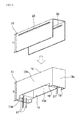
- Fig. 2 is an exploded perspective view showing a case and a cover that are used for the magnetic sensor according to the first embodiment. Description will be given with reference to Figs. 1A, 1B , and 2 .
- a magnetic sensor 10 includes a case 11, a magnet 31, a magnetoresistive element 33, and a cover 21.
- the case 11 is a substantially rectangular-parallelepiped box case having a lower plane being open.
- the case 11 includes a substantially rectangular upper wall 12, and a plurality of side walls 13a, 13b, 13c, and 13d that respectively extend from edges of the upper wall 12 substantially perpendicularly from a principal plane of the upper wall 12.
- the case 11 has a housing portion 14 being open to the lower side of the case 11.
- the housing portion 14 has steps near the side walls 13a and 13c.
- the case 11 is made of polyphenylene sulfide (PPS) resin.
- the material of the case 11 may be a thermoplastic resin such as liquid crystal polymer (LCP), or a thermosetting resin such as phenolic resin.
- Pin terminals 37 are provided at the steps of the housing portion 14.
- the pin terminals 37 penetrate through the steps of the housing portion 14. First ends of the pin terminals 37 are exposed from the upper wall 12 of the case 11, and second ends of the pin terminals 37 extend to the lower side of the case 11.
- the pin terminals 37 are used for electrically connect the magnetic sensor with an external circuit.
- the material of the pin terminals 37 may be a copper alloy treated by tinning.
- the magnet 31 is made of a substantially rectangular-parallelepiped magnetic material.
- the magnetoresistive element 33 includes a substantially rectangular element body and lead terminals (not shown) extending from an end portion of the element body.
- the magnetoresistive element 33 is an element having a resistance value that is variable in accordance with a change of a magnetic field.
- the magnetoresistive element 33 is fabricated, for example, by forming an InSb film on a surface of a silicon substrate.
- the magnet 31 is provided inside the case 11, and the magnetoresistive element 33 is provided outside the case 11, with the upper wall 12 interposed between the magnet 31 and the magnetoresistive element 33.
- the magnet 31 is housed in the housing portion 14 such that a surface of the magnet 31 contacts the inner side of the upper wall 12.
- the magnetoresistive element 33 is housed in a recess portion that is provided at the outer side of the upper wall 12.
- the element body of the magnetoresistive element 33 is bonded to a bottom surface of the recess portion with an adhesive layer 39 interposed between the element body and the bottom surface.
- the lead terminals are electrically connected with the first ends of the pin terminals 37.
- the recess portion has a depth that is larger than a combined thickness of the magnetoresistive element 33 and the adhesive later 39.
- the magnet 31 is provided to apply a biased magnetic field to the magnetoresistive element 33.
- an area of a portion of the magnet 31 facing the magnetoresistive element 33 is designed to be larger than an area of a portion of the magnetoresistive element 33 facing the magnet 31.
- the magnetoresistive element 33 may be other magnetoelectric conversion element such as a Hall element.
- the material of the adhesive layer 39 is preferably a silicon resin or the like with a high elastic coefficient so as to absorb mechanical vibration from the outside.
- the magnetoresistive element 33 may be directly attached to the outer side of the upper wall 12 of the case 11.
- a protrusion protruding by a height that is larger than the thickness of the magnetoresistive element 33 may be provided at the case 11, as a positioning member.
- the magnetoresistive element 33 may be fixed by the protrusion.
- the cover 21 includes three members that respectively cover the upper wall 12 of the case 11 and the two facing side walls 13b and 13d among the plurality of side walls of the case 11.
- the cover 21 is formed by bending a stainless-steel plate member.
- the material of the cover 21 may be a metal other than the stainless steel, or a conductive resin.
- the housing portion 14 of the case 11 is filled with a resin 35 that is made of a thermosetting resin such as epoxy resin to fix the magnet 31.
- the resin 35 leaking from the housing portion 14 is spread into a space between the case 11 and the cover 21, which closely contact each other, by a capillary action.
- the resin 35 fixes the magnet 31, and bonds the cover 21 to the case 11.
- the cover attachment grooves do not have to be provided.
- the size of the case 11 can be reduced by the amount of the cover attachment grooves. Accordingly, the size of the magnetic sensor 10 can be reduced.
- the cover 21 is formed preferably to cover the entire surfaces of the two facing side walls 13b and 13d of the case 11.
- the cover 21 preferably has a height H larger than a height h of the side walls 13a, 13b, 13c, and 13d of the case 11. Accordingly, the resin 35 can be reliably spread into the space between the case 11 and the cover 21.
- the side walls 13b and 13d of the case 11 covered with the cover 21 have notches 16. With the notches 16, the resin 35 can reliably leak from the case 11 even if the amount of the resin 35 is small.
- the side walls 13b and 13d of the case 11 covered with the cover 21 also have grooves 15 that prevent the resin 35 from reaching the magnetoresistive element 33 even if the amount of the resin 35 is large.
- the resin 35 spreading into the space between the case 11 and the cover 21 by the capillary action flows into the grooves 15 but does not flow to the magnetoresistive element 33.
- the grooves 15 are provided at the side walls 13b and 13d preferably at positions near the upper wall 12. Accordingly, the amount of the resin 35 flowing into the grooves 15 is decreased, and a bonding area between the case 11 and the cover 21 is increased.
- the number of the groove 15 may be plural.
- the groove 15 is provided preferably in parallel to lines on which the side walls 13b and 13d contact the upper wall 12. In this case, the groove 15 can be easily formed.
- FIG. 3 is a cross-sectional view when the magnetic sensor according to the first embodiment is used for a bill identifying device.
- a bill identifying device 1 includes the magnetic sensor 10, a stage 55 that supports the magnetic sensor 10, and a roller 51 provided at a position at which the roller 51 faces the magnetic sensor 10.
- a rotation direction of the roller 51 is a direction indicated by arrow R.
- a detection subject 53 such as a bill (paper money) is conveyed along a circumferential surface of the roller 51 in a direction indicated by arrow X.
- the magnetic sensor according to this embodiment is manufactured as follows.
- a case made of PPS resin and fabricated by ejection molding is prepared. Then, pin terminals are press-fitted into the case.
- the pin terminals are substantially round bars formed such that a copper alloy material is treated by tinning.
- a magnetoresistive element is provided outside an upper wall of the case.
- An element body having a plurality of resistive elements is prepared.
- a frame formed such that a copper material is treated by tinning is prepared.
- First ends of a plurality of lead terminals are commonly coupled with the frame.
- An end portion of the element body is connected with second ends of the lead terminals, and then the lead terminals are separated from the frame. Accordingly, the magnetoresistive element is formed.
- the magnetoresistive element is bonded and fixed to a recess portion of the case with silicon resin.
- the lead terminals and the pin terminals are bonded by heat sealing at a temperature in a range from about 360 to about 400 degrees centigrade, and hence are electrically connected with each other.
- the inside of the case is filled with epoxy resin, which is a thermosetting resin, to bond and fix the case and the magnet together, and the case and the cover together simultaneously at a temperature of about 120 degrees centigrade.
- epoxy resin which is a thermosetting resin
- the resin leaking from the housing portion is spread into a space between the case and the cover, which closely contact each other, by a capillary action. Hence, the resin fixes the magnet, and simultaneously, bonds the cover to the case.
- the magnetic sensor is manufactured by the above-described method.
- Fig. 4 is an exploded perspective view showing a case and a cover that are used for a magnetic sensor according to a second embodiment of the invention. Description for part of the second embodiment common to the first embodiment is omitted.
- holes 17 are formed at the side walls 13b and 13d of the case 11 covered with the cover 21, instead of the notches.
- the holes 17 can cause the resin 35 to smoothly flow from the housing portion 14 in the case 11 to the space between the case 11 and the cover 21, in a manner similar to the notches.
- Fig. 5 is an exploded perspective view showing a case and a cover that are used for a magnetic sensor according to a third embodiment of the invention.
- a hole 23 may be provided at a portion of the cover 21 covering the side walls 13b and 13d, as a structure that attains an advantage similar to the advantage of the grooves at the case.
- the holes 23 each may have any shape like a substantially circular shape or a substantially rectangular shape.
- a gap between the case 11 and the cover 21 is increased at edges of the hole 23. Hence, flow of the resin is stopped by surface tension. If both the grooves at the case 11 and the holes 23 at the cover 21 are provided, the flow of the resin can be effectively controlled. Thus, this structure is preferable.
- grooves may be formed at the cover 21 at portions covering the side walls 13b and 13d, so as to increase gaps between the cover 21 and the side walls 13b and 13d.
- the gap between the case 11 and the cover 21 is increased at the grooves, and the flow of the resin is stopped by surface tension.
Landscapes
- Physics & Mathematics (AREA)
- Condensed Matter Physics & Semiconductors (AREA)
- General Physics & Mathematics (AREA)
- Engineering & Computer Science (AREA)
- Manufacturing & Machinery (AREA)
- Measuring Magnetic Variables (AREA)
Abstract
Description
- The present invention relates to a magnetic sensor that identifies a bill (paper money) or the like.
- A magnetic sensor is used for reading and identifying information such as a number, a character, or a symbol printed with a magnetic ink etc. on a detection object such as a bill or a security. The magnetic sensor is arranged in a bill identifying device of, for example, an automated teller machine (ATM). For example, such a magnetic sensor is disclosed in Japanese Unexamined Patent Application Publication No.
2010-175490 Fig. 6 , the magnetic sensor disclosed in Japanese Unexamined Patent Application Publication No.2010-175490 case 110, acover 115, amagnetoresistive element 111 and amagnet 114. Thecase 110 hascover attachment grooves 121 at side surfaces of thecase 110. Thecover 115 includes a top portion that faces a magnetism detection surface, and side portions that are formed substantially perpendicularly to the top portion. The side portions of thecover 115 are inserted into thecover attachment grooves 121. Thecover attachment grooves 121 are filled with athermosetting resin 116. Thecase 110 and thecover 115 are fixed with theresin 116. - As described above, with the magnetic sensor of related art, the case and cover are attached together by a method of fitting the cover into the cover attachment grooves of the case, then filling the cover attachment grooves with the resin, and hardening the resin. Hence, the process may be complicated. Also, since the cover attachment grooves are provided at the side portions of the case, the size of the magnetic sensor may be increased.
- An aim of the present invention is to provide a small magnetic sensor by a simple process. The present invention is defined in the independent claim to which reference is now directed. Preferred features are set out in the dependent claims.
- According to preferred embodiments of the present invention, a magnetic sensor includes a substantially rectangular-parallelepiped case including an upper wall and a plurality of side walls extending from the upper wall substantially perpendicularly to the upper wall, the case having a housing portion therein; a magnet provided in the housing portion; a magnetoelectric conversion element provided outside the upper wall of the case; and a cover provided to cover the upper wall and the plurality of side walls. A resin, which is the same as a resin that fills a space between the housing portion of the case and the magnet and a space between the case and the cover, bonds and fixes the case and the magnet together and the case and the cover together.
- Preferably in the magnetic sensor, the cover may be provided to cover the upper wall and two facing side walls among the plurality of side walls.
- Preferably in the magnetic sensor, the cover may be provided to cover the entire surfaces of the two facing side walls of the case.
- Preferably in the magnetic sensor, a notch may be provided at the side walls of the case covered with the cover.
- Preferably in the magnetic sensor, a hole may be provided at the side walls of the case covered with the cover.
- Preferably in the magnetic sensor, a groove that prevents the flow of the resin may be provided at the side walls of the case covered with the cover.
- Preferably in the magnetic sensor, the groove may be provided at the side walls at a position near the upper wall.
- Preferably in the magnetic sensor, the groove may be provided in parallel to lines on which the side walls contact the upper wall.
- Preferably in the magnetic sensor, at least a hole that stops the flow of the resin is provided at a portion of the cover covering the side walls of the case.
- With the preferred embodiments of the present invention fixing of the magnet, and fixing of the cover and the case are simultaneously performed with the same resin. Accordingly, the case can be fixed by the simple process. Also, since the cover attachment grooves do not have to be provided unlike the process of related art, the size of the magnetic sensor can be reduced.
- Other features, elements, characteristics and advantages of the present invention will become more apparent from the following detailed description of preferred embodiments of the present invention with reference to the attached drawings.
- Preferred embodiments of the present invention will now be described, by way of example only, with reference to the accompanying drawings, in which:
-
Fig. 1A is a perspective view showing a magnetic sensor according to a first embodiment of the invention, andFig. 1B is a cross―sectional view taken along line M-M inFig. 1A according to the first embodiment; -
Fig. 2 is an exploded perspective view showing a case and a cover that are used for the magnetic sensor according to the first embodiment; -
Fig. 3 is a cross-sectional view when the magnetic sensor according to the first embodiment is used for a bill identifying device; -
Fig. 4 is an exploded perspective view showing a case and a cover that are used for a magnetic sensor according to a second embodiment of the invention; -
Fig. 5 is an exploded perspective view showing a case and a cover that are used for a magnetic sensor according to a third embodiment of the invention; and -
Fig. 6 is a cross-sectional view showing a magnetic sensor according to related art. - Embodiments for implementing the present invention will be described below.
-
Fig. 1A is a perspective view showing a magnetic sensor according to a first embodiment of the invention.Fig. 1B is a cross-sectional view taken along line M-M inFig. 1A . Also,Fig. 2 is an exploded perspective view showing a case and a cover that are used for the magnetic sensor according to the first embodiment. Description will be given with reference toFigs. 1A, 1B , and2 . - Referring to
Fig. 1B , amagnetic sensor 10 includes acase 11, amagnet 31, amagnetoresistive element 33, and acover 21. - Referring to
Fig. 2 , thecase 11 is a substantially rectangular-parallelepiped box case having a lower plane being open. In particular, thecase 11 includes a substantially rectangularupper wall 12, and a plurality ofside walls upper wall 12 substantially perpendicularly from a principal plane of theupper wall 12. Thecase 11 has ahousing portion 14 being open to the lower side of thecase 11. Thehousing portion 14 has steps near theside walls case 11 is made of polyphenylene sulfide (PPS) resin. Alternatively, the material of thecase 11 may be a thermoplastic resin such as liquid crystal polymer (LCP), or a thermosetting resin such as phenolic resin. -
Pin terminals 37 are provided at the steps of thehousing portion 14. Thepin terminals 37 penetrate through the steps of thehousing portion 14. First ends of thepin terminals 37 are exposed from theupper wall 12 of thecase 11, and second ends of thepin terminals 37 extend to the lower side of thecase 11. Thepin terminals 37 are used for electrically connect the magnetic sensor with an external circuit. The material of thepin terminals 37 may be a copper alloy treated by tinning. - The
magnet 31 is made of a substantially rectangular-parallelepiped magnetic material. Themagnetoresistive element 33 includes a substantially rectangular element body and lead terminals (not shown) extending from an end portion of the element body. Themagnetoresistive element 33 is an element having a resistance value that is variable in accordance with a change of a magnetic field. Themagnetoresistive element 33 is fabricated, for example, by forming an InSb film on a surface of a silicon substrate. - Referring to
Fig. 1B , themagnet 31 is provided inside thecase 11, and themagnetoresistive element 33 is provided outside thecase 11, with theupper wall 12 interposed between themagnet 31 and themagnetoresistive element 33. To be more specific, themagnet 31 is housed in thehousing portion 14 such that a surface of themagnet 31 contacts the inner side of theupper wall 12. Themagnetoresistive element 33 is housed in a recess portion that is provided at the outer side of theupper wall 12. The element body of themagnetoresistive element 33 is bonded to a bottom surface of the recess portion with anadhesive layer 39 interposed between the element body and the bottom surface. The lead terminals are electrically connected with the first ends of thepin terminals 37. The recess portion has a depth that is larger than a combined thickness of themagnetoresistive element 33 and the adhesive later 39. Themagnet 31 is provided to apply a biased magnetic field to themagnetoresistive element 33. Hence, an area of a portion of themagnet 31 facing themagnetoresistive element 33 is designed to be larger than an area of a portion of themagnetoresistive element 33 facing themagnet 31. - The
magnetoresistive element 33 may be other magnetoelectric conversion element such as a Hall element. The material of theadhesive layer 39 is preferably a silicon resin or the like with a high elastic coefficient so as to absorb mechanical vibration from the outside. Alternatively, themagnetoresistive element 33 may be directly attached to the outer side of theupper wall 12 of thecase 11. In this case, for example, a protrusion protruding by a height that is larger than the thickness of themagnetoresistive element 33 may be provided at thecase 11, as a positioning member. Themagnetoresistive element 33 may be fixed by the protrusion. - Referring to
Fig. 2 , thecover 21 includes three members that respectively cover theupper wall 12 of thecase 11 and the two facingside walls case 11. In this embodiment, thecover 21 is formed by bending a stainless-steel plate member. Hence, thecover 21 can be easily processed. Alternatively, the material of thecover 21 may be a metal other than the stainless steel, or a conductive resin. - Referring to
Fig. 1B , thehousing portion 14 of thecase 11 is filled with aresin 35 that is made of a thermosetting resin such as epoxy resin to fix themagnet 31. Theresin 35 leaking from thehousing portion 14 is spread into a space between thecase 11 and thecover 21, which closely contact each other, by a capillary action. Hence, theresin 35 fixes themagnet 31, and bonds thecover 21 to thecase 11. Further, unlike the case of related art, the cover attachment grooves do not have to be provided. The size of thecase 11 can be reduced by the amount of the cover attachment grooves. Accordingly, the size of themagnetic sensor 10 can be reduced. - The
cover 21 is formed preferably to cover the entire surfaces of the two facingside walls case 11. In particular, as shown inFig. 2 , thecover 21 preferably has a height H larger than a height h of theside walls case 11. Accordingly, theresin 35 can be reliably spread into the space between thecase 11 and thecover 21. - The
side walls case 11 covered with thecover 21 havenotches 16. With thenotches 16, theresin 35 can reliably leak from thecase 11 even if the amount of theresin 35 is small. - The
side walls case 11 covered with thecover 21 also havegrooves 15 that prevent theresin 35 from reaching themagnetoresistive element 33 even if the amount of theresin 35 is large. Theresin 35 spreading into the space between thecase 11 and thecover 21 by the capillary action flows into thegrooves 15 but does not flow to themagnetoresistive element 33. Thegrooves 15 are provided at theside walls upper wall 12. Accordingly, the amount of theresin 35 flowing into thegrooves 15 is decreased, and a bonding area between thecase 11 and thecover 21 is increased. The number of thegroove 15 may be plural. Also, thegroove 15 is provided preferably in parallel to lines on which theside walls upper wall 12. In this case, thegroove 15 can be easily formed. - A problem that occurs if the
resin 35 reaches themagnetoresistive element 33 will be described below.Fig. 3 is a cross-sectional view when the magnetic sensor according to the first embodiment is used for a bill identifying device. Abill identifying device 1 includes themagnetic sensor 10, astage 55 that supports themagnetic sensor 10, and aroller 51 provided at a position at which theroller 51 faces themagnetic sensor 10. A rotation direction of theroller 51 is a direction indicated by arrow R.A detection subject 53 such as a bill (paper money) is conveyed along a circumferential surface of theroller 51 in a direction indicated by arrow X. - If no gap is provided between the
cover 21 and themagnetoresistive element 33, a pressure from theroller 51 directly propagates to themagnetoresistive element 33, and a noise is generated as the result of the pressure. Owing to this, a phenomenon in which theresin 35 reaches themagnetoresistive element 33 and fills the gap has to be prevented from occurring. - For example, the magnetic sensor according to this embodiment is manufactured as follows.
- First, a case made of PPS resin and fabricated by ejection molding is prepared. Then, pin terminals are press-fitted into the case. The pin terminals are substantially round bars formed such that a copper alloy material is treated by tinning.
- Then, a magnetoresistive element is provided outside an upper wall of the case. An element body having a plurality of resistive elements is prepared. Then, a frame formed such that a copper material is treated by tinning is prepared. First ends of a plurality of lead terminals are commonly coupled with the frame. An end portion of the element body is connected with second ends of the lead terminals, and then the lead terminals are separated from the frame. Accordingly, the magnetoresistive element is formed. The magnetoresistive element is bonded and fixed to a recess portion of the case with silicon resin. Then, the lead terminals and the pin terminals are bonded by heat sealing at a temperature in a range from about 360 to about 400 degrees centigrade, and hence are electrically connected with each other.
- Next, while an open part of a housing portion of the case is directed upward, a magnet is inserted into the housing portion defined in the case.
- Then, a cover is fitted to the case from the upper wall side.
- Then, the inside of the case is filled with epoxy resin, which is a thermosetting resin, to bond and fix the case and the magnet together, and the case and the cover together simultaneously at a temperature of about 120 degrees centigrade. The resin leaking from the housing portion is spread into a space between the case and the cover, which closely contact each other, by a capillary action. Hence, the resin fixes the magnet, and simultaneously, bonds the cover to the case.
- The magnetic sensor is manufactured by the above-described method.
- Also,
Fig. 4 is an exploded perspective view showing a case and a cover that are used for a magnetic sensor according to a second embodiment of the invention. Description for part of the second embodiment common to the first embodiment is omitted. - In this embodiment, holes 17 are formed at the
side walls case 11 covered with thecover 21, instead of the notches. Theholes 17 can cause theresin 35 to smoothly flow from thehousing portion 14 in thecase 11 to the space between thecase 11 and thecover 21, in a manner similar to the notches. -
Fig. 5 is an exploded perspective view showing a case and a cover that are used for a magnetic sensor according to a third embodiment of the invention. - Referring to
Fig. 5 , preferably, at least ahole 23 may be provided at a portion of thecover 21 covering theside walls holes 23 each may have any shape like a substantially circular shape or a substantially rectangular shape. A gap between thecase 11 and thecover 21 is increased at edges of thehole 23. Hence, flow of the resin is stopped by surface tension. If both the grooves at thecase 11 and theholes 23 at thecover 21 are provided, the flow of the resin can be effectively controlled. Thus, this structure is preferable. - Alternatively, as a structure that attains an advantage similar to the advantage of the grooves at the case, grooves may be formed at the
cover 21 at portions covering theside walls cover 21 and theside walls case 11 and thecover 21 is increased at the grooves, and the flow of the resin is stopped by surface tension. - While preferred embodiments of the invention have been described above, it is to be understood that variations and modifications will be apparent to those skilled in the art without departing from the scope of the invention. The scope of the invention, therefore, is to be determined solely by the following claims.
Claims (9)
- A magnetic sensor (10), comprising:a substantially rectangular-parallelepiped case (11) including an upper wall (12) and a plurality of side walls (13a, 13b, 13c, 13d) extending from the upper wall substantially perpendicularly to the upper wall, the case having a housing portion (14) inside;a magnet (31) provided in the housing portion;a magnetoelectric conversion element (33) provided outside the upper wall of the case; anda cover (21) provided to cover the upper wall and the plurality of side walls,wherein a resin (35), which is the same as a resin that fills a space between the housing portion of the case and the magnet and a space between the case and the cover, bonds and fixes the case and the magnet together and the case and the cover together.
- The magnetic sensor according to claim 1, wherein the cover is provided to cover the upper wall and two facing side walls (13b, 13d) among the plurality of side walls.
- The magnetic sensor according to claim 2, wherein the cover is provided to cover the entire surfaces of the two facing side walls among the plurality of side walls.
- The magnetic sensor according to any of claims 1 to 3, wherein a notch (16) is provided at the plurality of side walls covered with the cover.
- The magnetic sensor according to any of claims 1 to 4, wherein a hole (17) is provided at the plurality of side walls covered with the cover.
- The magnetic sensor according to any of claims 1 to 5, wherein a groove (15) that prevents the flow of the resin is provided at the plurality of side walls covered with the cover.
- The magnetic sensor according to claim 6, wherein the groove is provided at the plurality of side walls at a position near the upper wall.
- The magnetic sensor according to claim 6 or 7, wherein the groove is provided in parallel to a line on which the plurality of side walls contact the upper wall.
- The magnetic sensor according to any of claims 1 to 8, wherein at least a hole (23) that prevents the flow of the resin is provided at a portion of the cover where the cover covers the plurality of side walls.
Applications Claiming Priority (1)
| Application Number | Priority Date | Filing Date | Title |
|---|---|---|---|
| JP2010244756A JP5240276B2 (en) | 2010-10-29 | 2010-10-29 | Magnetic sensor |
Publications (2)
| Publication Number | Publication Date |
|---|---|
| EP2447731A1 true EP2447731A1 (en) | 2012-05-02 |
| EP2447731B1 EP2447731B1 (en) | 2013-07-03 |
Family
ID=45047572
Family Applications (1)
| Application Number | Title | Priority Date | Filing Date |
|---|---|---|---|
| EP20110186111 Not-in-force EP2447731B1 (en) | 2010-10-29 | 2011-10-21 | Magnetic sensor |
Country Status (3)
| Country | Link |
|---|---|
| EP (1) | EP2447731B1 (en) |
| JP (1) | JP5240276B2 (en) |
| CN (1) | CN102564465A (en) |
Cited By (1)
| Publication number | Priority date | Publication date | Assignee | Title |
|---|---|---|---|---|
| US20180313911A1 (en) * | 2014-07-25 | 2018-11-01 | Mitsubishi Electric Corporation | Magnetic sensor device having an enclosure with step portions and grooves continuous with the step portions and method of manufacture thereof |
Families Citing this family (4)
| Publication number | Priority date | Publication date | Assignee | Title |
|---|---|---|---|---|
| JP6111507B2 (en) * | 2012-08-31 | 2017-04-12 | パナソニックIpマネジメント株式会社 | Locking detection device for joinery |
| CN103971444A (en) * | 2013-01-29 | 2014-08-06 | 北京嘉岳同乐极电子有限公司 | Magnetic sensor for magnetic detection |
| EP3736841B1 (en) * | 2018-01-25 | 2025-12-17 | Murata Manufacturing Co., Ltd. | Film capacitor, and exterior case for film capacitor |
| KR102908472B1 (en) * | 2024-09-03 | 2026-01-06 | 한국전자통신연구원 | Radio frequency magnetic sensor for magnetic field communication and manufacturing method of the same |
Citations (2)
| Publication number | Priority date | Publication date | Assignee | Title |
|---|---|---|---|---|
| JP2010127756A (en) * | 2008-11-27 | 2010-06-10 | Yaskawa Electric Corp | Encoder sensor for vacuum, and motor for vacuum including same |
| JP2010175490A (en) | 2009-02-02 | 2010-08-12 | Murata Mfg Co Ltd | Manufacturing method of magnetic sensor and magnetic sensor |
Family Cites Families (5)
| Publication number | Priority date | Publication date | Assignee | Title |
|---|---|---|---|---|
| JPH0720625Y2 (en) * | 1989-09-21 | 1995-05-15 | 株式会社村田製作所 | Magnetoresistive sensor |
| JP3314548B2 (en) * | 1994-09-16 | 2002-08-12 | 松下電器産業株式会社 | Magnetic detector |
| US7639196B2 (en) * | 2001-07-10 | 2009-12-29 | Andrew Llc | Cellular antenna and systems and methods therefor |
| JP3775296B2 (en) * | 2001-12-12 | 2006-05-17 | 株式会社村田製作所 | Magnetic sensor |
| CN2788259Y (en) * | 2005-04-15 | 2006-06-14 | 福建省电影机械厂 | Huge magnetic resistance sensor of paper money counter |
-
2010
- 2010-10-29 JP JP2010244756A patent/JP5240276B2/en active Active
-
2011
- 2011-10-21 EP EP20110186111 patent/EP2447731B1/en not_active Not-in-force
- 2011-10-28 CN CN2011103337672A patent/CN102564465A/en active Pending
Patent Citations (2)
| Publication number | Priority date | Publication date | Assignee | Title |
|---|---|---|---|---|
| JP2010127756A (en) * | 2008-11-27 | 2010-06-10 | Yaskawa Electric Corp | Encoder sensor for vacuum, and motor for vacuum including same |
| JP2010175490A (en) | 2009-02-02 | 2010-08-12 | Murata Mfg Co Ltd | Manufacturing method of magnetic sensor and magnetic sensor |
Cited By (1)
| Publication number | Priority date | Publication date | Assignee | Title |
|---|---|---|---|---|
| US20180313911A1 (en) * | 2014-07-25 | 2018-11-01 | Mitsubishi Electric Corporation | Magnetic sensor device having an enclosure with step portions and grooves continuous with the step portions and method of manufacture thereof |
Also Published As
| Publication number | Publication date |
|---|---|
| CN102564465A (en) | 2012-07-11 |
| JP5240276B2 (en) | 2013-07-17 |
| EP2447731B1 (en) | 2013-07-03 |
| JP2012098095A (en) | 2012-05-24 |
Similar Documents
| Publication | Publication Date | Title |
|---|---|---|
| EP2447731B1 (en) | Magnetic sensor | |
| EP2187435B1 (en) | Electronic component | |
| US8358122B2 (en) | Current sensor with laminated magnetic core | |
| CN108541319B (en) | Electronic sensor supported on rigid substrate | |
| WO2019117171A1 (en) | Current sensor and current sensor case manufacturing method | |
| JP6123578B2 (en) | Manufacturing method of liquid level detection device | |
| WO2016013438A1 (en) | Magnetic sensor device and method of manufacture thereof | |
| CN115702543B (en) | Temperature sensor and rotating electrical machine | |
| JP2004354254A (en) | Current sensor | |
| JPH11304894A (en) | Magnetic detection device and method of manufacturing the same | |
| JP2015159224A (en) | sensor structure | |
| JP2008151792A5 (en) | ||
| JP2015200546A (en) | sensor structure | |
| KR102212845B1 (en) | Gas sensor package | |
| JP2006504193A (en) | Smart card including accessible components and method of manufacturing the same | |
| US20150260564A1 (en) | Sensor | |
| JP4881041B2 (en) | Magnetic sensor device | |
| JP5593704B2 (en) | Magnetic detection element, rotation angle detection device and stroke amount detection device using the same | |
| WO2013132815A1 (en) | Module with embedded electronic components, electronic device, and method for manufacturing module with embedded electronic components | |
| JP4647755B2 (en) | Capacitance sensor | |
| JP6469335B2 (en) | Magnetic sensor device | |
| KR20100063364A (en) | Laminated sheet integrated with antenna coil including rf chip module and a method for manufacturing the same | |
| JP2011145188A (en) | Moving body detector | |
| JP2010185740A (en) | Sensor device | |
| JP5233916B2 (en) | Rotation detector |
Legal Events
| Date | Code | Title | Description |
|---|---|---|---|
| PUAI | Public reference made under article 153(3) epc to a published international application that has entered the european phase |
Free format text: ORIGINAL CODE: 0009012 |
|
| 17P | Request for examination filed |
Effective date: 20111121 |
|
| AK | Designated contracting states |
Kind code of ref document: A1 Designated state(s): AL AT BE BG CH CY CZ DE DK EE ES FI FR GB GR HR HU IE IS IT LI LT LU LV MC MK MT NL NO PL PT RO RS SE SI SK SM TR |
|
| AX | Request for extension of the european patent |
Extension state: BA ME |
|
| GRAP | Despatch of communication of intention to grant a patent |
Free format text: ORIGINAL CODE: EPIDOSNIGR1 |
|
| RIC1 | Information provided on ipc code assigned before grant |
Ipc: G01R 33/00 20060101AFI20130103BHEP |
|
| GRAS | Grant fee paid |
Free format text: ORIGINAL CODE: EPIDOSNIGR3 |
|
| GRAA | (expected) grant |
Free format text: ORIGINAL CODE: 0009210 |
|
| AK | Designated contracting states |
Kind code of ref document: B1 Designated state(s): AL AT BE BG CH CY CZ DE DK EE ES FI FR GB GR HR HU IE IS IT LI LT LU LV MC MK MT NL NO PL PT RO RS SE SI SK SM TR |
|
| REG | Reference to a national code |
Ref country code: GB Ref legal event code: FG4D |
|
| REG | Reference to a national code |
Ref country code: AT Ref legal event code: REF Ref document number: 620067 Country of ref document: AT Kind code of ref document: T Effective date: 20130715 Ref country code: CH Ref legal event code: EP |
|
| REG | Reference to a national code |
Ref country code: IE Ref legal event code: FG4D |
|
| REG | Reference to a national code |
Ref country code: DE Ref legal event code: R096 Ref document number: 602011002214 Country of ref document: DE Effective date: 20130829 |
|
| PG25 | Lapsed in a contracting state [announced via postgrant information from national office to epo] |
Ref country code: SI Free format text: LAPSE BECAUSE OF FAILURE TO SUBMIT A TRANSLATION OF THE DESCRIPTION OR TO PAY THE FEE WITHIN THE PRESCRIBED TIME-LIMIT Effective date: 20130703 |
|
| REG | Reference to a national code |
Ref country code: AT Ref legal event code: MK05 Ref document number: 620067 Country of ref document: AT Kind code of ref document: T Effective date: 20130703 |
|
| REG | Reference to a national code |
Ref country code: NL Ref legal event code: VDEP Effective date: 20130703 |
|
| REG | Reference to a national code |
Ref country code: LT Ref legal event code: MG4D |
|
| PG25 | Lapsed in a contracting state [announced via postgrant information from national office to epo] |
Ref country code: IS Free format text: LAPSE BECAUSE OF FAILURE TO SUBMIT A TRANSLATION OF THE DESCRIPTION OR TO PAY THE FEE WITHIN THE PRESCRIBED TIME-LIMIT Effective date: 20131103 Ref country code: LT Free format text: LAPSE BECAUSE OF FAILURE TO SUBMIT A TRANSLATION OF THE DESCRIPTION OR TO PAY THE FEE WITHIN THE PRESCRIBED TIME-LIMIT Effective date: 20130703 Ref country code: PT Free format text: LAPSE BECAUSE OF FAILURE TO SUBMIT A TRANSLATION OF THE DESCRIPTION OR TO PAY THE FEE WITHIN THE PRESCRIBED TIME-LIMIT Effective date: 20131104 Ref country code: HR Free format text: LAPSE BECAUSE OF FAILURE TO SUBMIT A TRANSLATION OF THE DESCRIPTION OR TO PAY THE FEE WITHIN THE PRESCRIBED TIME-LIMIT Effective date: 20130703 Ref country code: NO Free format text: LAPSE BECAUSE OF FAILURE TO SUBMIT A TRANSLATION OF THE DESCRIPTION OR TO PAY THE FEE WITHIN THE PRESCRIBED TIME-LIMIT Effective date: 20131003 Ref country code: BE Free format text: LAPSE BECAUSE OF FAILURE TO SUBMIT A TRANSLATION OF THE DESCRIPTION OR TO PAY THE FEE WITHIN THE PRESCRIBED TIME-LIMIT Effective date: 20130703 Ref country code: CY Free format text: LAPSE BECAUSE OF FAILURE TO SUBMIT A TRANSLATION OF THE DESCRIPTION OR TO PAY THE FEE WITHIN THE PRESCRIBED TIME-LIMIT Effective date: 20130821 Ref country code: AT Free format text: LAPSE BECAUSE OF FAILURE TO SUBMIT A TRANSLATION OF THE DESCRIPTION OR TO PAY THE FEE WITHIN THE PRESCRIBED TIME-LIMIT Effective date: 20130703 Ref country code: SE Free format text: LAPSE BECAUSE OF FAILURE TO SUBMIT A TRANSLATION OF THE DESCRIPTION OR TO PAY THE FEE WITHIN THE PRESCRIBED TIME-LIMIT Effective date: 20130703 |
|
| PG25 | Lapsed in a contracting state [announced via postgrant information from national office to epo] |
Ref country code: ES Free format text: LAPSE BECAUSE OF FAILURE TO SUBMIT A TRANSLATION OF THE DESCRIPTION OR TO PAY THE FEE WITHIN THE PRESCRIBED TIME-LIMIT Effective date: 20131014 Ref country code: LV Free format text: LAPSE BECAUSE OF FAILURE TO SUBMIT A TRANSLATION OF THE DESCRIPTION OR TO PAY THE FEE WITHIN THE PRESCRIBED TIME-LIMIT Effective date: 20130703 Ref country code: NL Free format text: LAPSE BECAUSE OF FAILURE TO SUBMIT A TRANSLATION OF THE DESCRIPTION OR TO PAY THE FEE WITHIN THE PRESCRIBED TIME-LIMIT Effective date: 20130703 Ref country code: FI Free format text: LAPSE BECAUSE OF FAILURE TO SUBMIT A TRANSLATION OF THE DESCRIPTION OR TO PAY THE FEE WITHIN THE PRESCRIBED TIME-LIMIT Effective date: 20130703 Ref country code: PL Free format text: LAPSE BECAUSE OF FAILURE TO SUBMIT A TRANSLATION OF THE DESCRIPTION OR TO PAY THE FEE WITHIN THE PRESCRIBED TIME-LIMIT Effective date: 20130703 Ref country code: GR Free format text: LAPSE BECAUSE OF FAILURE TO SUBMIT A TRANSLATION OF THE DESCRIPTION OR TO PAY THE FEE WITHIN THE PRESCRIBED TIME-LIMIT Effective date: 20131004 |
|
| PG25 | Lapsed in a contracting state [announced via postgrant information from national office to epo] |
Ref country code: CY Free format text: LAPSE BECAUSE OF FAILURE TO SUBMIT A TRANSLATION OF THE DESCRIPTION OR TO PAY THE FEE WITHIN THE PRESCRIBED TIME-LIMIT Effective date: 20130703 |
|
| PG25 | Lapsed in a contracting state [announced via postgrant information from national office to epo] |
Ref country code: EE Free format text: LAPSE BECAUSE OF FAILURE TO SUBMIT A TRANSLATION OF THE DESCRIPTION OR TO PAY THE FEE WITHIN THE PRESCRIBED TIME-LIMIT Effective date: 20130703 Ref country code: RO Free format text: LAPSE BECAUSE OF FAILURE TO SUBMIT A TRANSLATION OF THE DESCRIPTION OR TO PAY THE FEE WITHIN THE PRESCRIBED TIME-LIMIT Effective date: 20130703 Ref country code: SK Free format text: LAPSE BECAUSE OF FAILURE TO SUBMIT A TRANSLATION OF THE DESCRIPTION OR TO PAY THE FEE WITHIN THE PRESCRIBED TIME-LIMIT Effective date: 20130703 Ref country code: DK Free format text: LAPSE BECAUSE OF FAILURE TO SUBMIT A TRANSLATION OF THE DESCRIPTION OR TO PAY THE FEE WITHIN THE PRESCRIBED TIME-LIMIT Effective date: 20130703 Ref country code: CZ Free format text: LAPSE BECAUSE OF FAILURE TO SUBMIT A TRANSLATION OF THE DESCRIPTION OR TO PAY THE FEE WITHIN THE PRESCRIBED TIME-LIMIT Effective date: 20130703 |
|
| PLBE | No opposition filed within time limit |
Free format text: ORIGINAL CODE: 0009261 |
|
| STAA | Information on the status of an ep patent application or granted ep patent |
Free format text: STATUS: NO OPPOSITION FILED WITHIN TIME LIMIT |
|
| PG25 | Lapsed in a contracting state [announced via postgrant information from national office to epo] |
Ref country code: IT Free format text: LAPSE BECAUSE OF FAILURE TO SUBMIT A TRANSLATION OF THE DESCRIPTION OR TO PAY THE FEE WITHIN THE PRESCRIBED TIME-LIMIT Effective date: 20130703 Ref country code: MC Free format text: LAPSE BECAUSE OF FAILURE TO SUBMIT A TRANSLATION OF THE DESCRIPTION OR TO PAY THE FEE WITHIN THE PRESCRIBED TIME-LIMIT Effective date: 20130703 |
|
| 26N | No opposition filed |
Effective date: 20140404 |
|
| REG | Reference to a national code |
Ref country code: DE Ref legal event code: R097 Ref document number: 602011002214 Country of ref document: DE Effective date: 20140404 |
|
| REG | Reference to a national code |
Ref country code: IE Ref legal event code: MM4A |
|
| REG | Reference to a national code |
Ref country code: FR Ref legal event code: ST Effective date: 20140630 |
|
| PG25 | Lapsed in a contracting state [announced via postgrant information from national office to epo] |
Ref country code: FR Free format text: LAPSE BECAUSE OF NON-PAYMENT OF DUE FEES Effective date: 20131031 |
|
| PG25 | Lapsed in a contracting state [announced via postgrant information from national office to epo] |
Ref country code: IE Free format text: LAPSE BECAUSE OF NON-PAYMENT OF DUE FEES Effective date: 20131021 |
|
| PG25 | Lapsed in a contracting state [announced via postgrant information from national office to epo] |
Ref country code: SM Free format text: LAPSE BECAUSE OF FAILURE TO SUBMIT A TRANSLATION OF THE DESCRIPTION OR TO PAY THE FEE WITHIN THE PRESCRIBED TIME-LIMIT Effective date: 20130703 |
|
| REG | Reference to a national code |
Ref country code: CH Ref legal event code: PL |
|
| PG25 | Lapsed in a contracting state [announced via postgrant information from national office to epo] |
Ref country code: TR Free format text: LAPSE BECAUSE OF FAILURE TO SUBMIT A TRANSLATION OF THE DESCRIPTION OR TO PAY THE FEE WITHIN THE PRESCRIBED TIME-LIMIT Effective date: 20130703 |
|
| PG25 | Lapsed in a contracting state [announced via postgrant information from national office to epo] |
Ref country code: HU Free format text: LAPSE BECAUSE OF FAILURE TO SUBMIT A TRANSLATION OF THE DESCRIPTION OR TO PAY THE FEE WITHIN THE PRESCRIBED TIME-LIMIT; INVALID AB INITIO Effective date: 20111021 Ref country code: LU Free format text: LAPSE BECAUSE OF NON-PAYMENT OF DUE FEES Effective date: 20131021 Ref country code: CH Free format text: LAPSE BECAUSE OF NON-PAYMENT OF DUE FEES Effective date: 20141031 Ref country code: LI Free format text: LAPSE BECAUSE OF NON-PAYMENT OF DUE FEES Effective date: 20141031 Ref country code: MK Free format text: LAPSE BECAUSE OF FAILURE TO SUBMIT A TRANSLATION OF THE DESCRIPTION OR TO PAY THE FEE WITHIN THE PRESCRIBED TIME-LIMIT Effective date: 20130703 Ref country code: RS Free format text: LAPSE BECAUSE OF FAILURE TO SUBMIT A TRANSLATION OF THE DESCRIPTION OR TO PAY THE FEE WITHIN THE PRESCRIBED TIME-LIMIT Effective date: 20131003 Ref country code: BG Free format text: LAPSE BECAUSE OF FAILURE TO SUBMIT A TRANSLATION OF THE DESCRIPTION OR TO PAY THE FEE WITHIN THE PRESCRIBED TIME-LIMIT Effective date: 20130703 |
|
| PG25 | Lapsed in a contracting state [announced via postgrant information from national office to epo] |
Ref country code: MT Free format text: LAPSE BECAUSE OF FAILURE TO SUBMIT A TRANSLATION OF THE DESCRIPTION OR TO PAY THE FEE WITHIN THE PRESCRIBED TIME-LIMIT Effective date: 20130703 |
|
| GBPC | Gb: european patent ceased through non-payment of renewal fee |
Effective date: 20151021 |
|
| PG25 | Lapsed in a contracting state [announced via postgrant information from national office to epo] |
Ref country code: GB Free format text: LAPSE BECAUSE OF NON-PAYMENT OF DUE FEES Effective date: 20151021 |
|
| PG25 | Lapsed in a contracting state [announced via postgrant information from national office to epo] |
Ref country code: AL Free format text: LAPSE BECAUSE OF FAILURE TO SUBMIT A TRANSLATION OF THE DESCRIPTION OR TO PAY THE FEE WITHIN THE PRESCRIBED TIME-LIMIT Effective date: 20130703 |
|
| PGFP | Annual fee paid to national office [announced via postgrant information from national office to epo] |
Ref country code: DE Payment date: 20201022 Year of fee payment: 10 |
|
| REG | Reference to a national code |
Ref country code: DE Ref legal event code: R119 Ref document number: 602011002214 Country of ref document: DE |
|
| PG25 | Lapsed in a contracting state [announced via postgrant information from national office to epo] |
Ref country code: DE Free format text: LAPSE BECAUSE OF NON-PAYMENT OF DUE FEES Effective date: 20220503 |