EP2447580A2 - Automatic bleed valve assembly - Google Patents
Automatic bleed valve assembly Download PDFInfo
- Publication number
- EP2447580A2 EP2447580A2 EP20110187165 EP11187165A EP2447580A2 EP 2447580 A2 EP2447580 A2 EP 2447580A2 EP 20110187165 EP20110187165 EP 20110187165 EP 11187165 A EP11187165 A EP 11187165A EP 2447580 A2 EP2447580 A2 EP 2447580A2
- Authority
- EP
- European Patent Office
- Prior art keywords
- movable member
- port
- inlet
- valve assembly
- chamber
- Prior art date
- Legal status (The legal status is an assumption and is not a legal conclusion. Google has not performed a legal analysis and makes no representation as to the accuracy of the status listed.)
- Withdrawn
Links
Images


Classifications
-
- F—MECHANICAL ENGINEERING; LIGHTING; HEATING; WEAPONS; BLASTING
- F16—ENGINEERING ELEMENTS AND UNITS; GENERAL MEASURES FOR PRODUCING AND MAINTAINING EFFECTIVE FUNCTIONING OF MACHINES OR INSTALLATIONS; THERMAL INSULATION IN GENERAL
- F16K—VALVES; TAPS; COCKS; ACTUATING-FLOATS; DEVICES FOR VENTING OR AERATING
- F16K24/00—Devices, e.g. valves, for venting or aerating enclosures
- F16K24/04—Devices, e.g. valves, for venting or aerating enclosures for venting only
-
- Y—GENERAL TAGGING OF NEW TECHNOLOGICAL DEVELOPMENTS; GENERAL TAGGING OF CROSS-SECTIONAL TECHNOLOGIES SPANNING OVER SEVERAL SECTIONS OF THE IPC; TECHNICAL SUBJECTS COVERED BY FORMER USPC CROSS-REFERENCE ART COLLECTIONS [XRACs] AND DIGESTS
- Y10—TECHNICAL SUBJECTS COVERED BY FORMER USPC
- Y10T—TECHNICAL SUBJECTS COVERED BY FORMER US CLASSIFICATION
- Y10T137/00—Fluid handling
- Y10T137/7722—Line condition change responsive valves
- Y10T137/7736—Consistency responsive
Definitions
- the present invention relates to an automatic bleed valve assembly. More particularly, the present invention relates to an automatic air bleed valve assembly for venting air from a fire hose attached to the intake of a fire truck pump.
- typical fire trucks (not shown) have an on-board water tank 1 (or reservoir) to allow the pumping of water onto a fire upon the immediate arrival of the fire truck at a fire scene.
- a large diameter lay-flat hose 2 is run from the fire truck to the nearest fire-scene-available water source 3, such as a fire hydrant (or a pressurized wet standpipe).
- a fire pump 5 generally a centrifugal pump
- the pump intake valve 4 is opened and the tank outlet valve 6 controlling the flow of water from the on-board water tank 1 is closed so that the fire pump is supplied with water from the hydrant or standpipe.
- an automatic intake air bleed valve assembly for venting air from the lay-flat hose without operator intervention is highly desirable.
- one aspect of the present invention is directed to an automatic bleed valve assembly for intake gas in an intake line supplying a liquid.
- the valve assembly comprises a body having an inlet port, an outlet port and a chamber in fluid communication with the inlet port and the outlet port.
- An inlet-port sealing surface is in the chamber.
- An outlet-port sealing surface is in the chamber.
- a movable member in the chamber is movable in translation between an inlet-port sealing position in which the movable member is in sealing contact with the inlet-port sealing surface and an outlet-port sealing position in which the movable member is in sealing contact with the outlet-port sealing surface.
- a biasing member operatively coupled to the movable member and to the chamber is configured to apply to the movable member a reactive force directed toward the inlet port, the reactive force being greater than a gas-resistance force applied to the movable member by the intake gas when the intake gas is flowing into the chamber and less than a liquid-resistance force applied to the movable member by the liquid when the liquid is flowing into the chamber.
- Fig. 1 is a schematic diagram of an embodiment of an automatic intake air bleed valve in accordance with the present invention as typically installed at a fire scene;
- Fig. 2 is an enlarged schematic diagram of the automatic intake air bleed valve of Fig. 1 ;
- Fig. 3 is a cross sectional view of the automatic intake air bleed valve of Fig. 1 ;
- Figs. 4A and 4B are cross sectional views of the automatic intake air bleed valve of Fig. 1 showing the movable member in a first position sealing the inlet port and a second position sealing the outlet port;
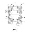
- Fig. 5 is a cross sectional view of another embodiment of an automatic intake air bleed valve in accordance with the present invention.
- Fig. 6 is a cross sectional view of still another embodiment of an automatic intake air bleed valve in accordance with the present invention.
- first, second, etc. are used herein to describe various elements, these elements should not be limited by these words. These words are only used to distinguish one element from another.
- a first tube could be termed a second tube, and, similarly, a second tube could be termed a first tube, without departing from the scope of the present invention.
- the words “if” may be construed to mean “when” or “upon” or “in response to determining” or “in response to detecting,” depending on the context.
- the phrase “if it is determined” or “if [a stated condition or event] is detected” may be construed to mean “upon determining” or “in response to determining” or “upon detecting [the stated condition or event]” or “in response to detecting [the stated condition or event],” depending on the context.
- valve assembly 10 in accordance with the present invention.
- the valve assembly 10 is for venting to atmosphere air entrapped in the water supply hose 2 attached to the intake valve 4 of a fire truck water pump 5.
- the valve assembly 10 has a body 12 with an inlet port 14 and an outlet port 16.
- the inlet port 14 is configured for fluid connection with a lay-flat hose 2 and an intake valve 4 of a fire pump 5.
- the connection may be through a "T” joint, "Y” joint or the like and typically requires a threaded or Storz connection (see, U.S. Patent No. 489,107 incorporated herein by reference).
- the valve assembly 10 may be integrated with the pump intake valve 4.
- the body 12 has an internal chamber 18 between the inlet port 14 and the outlet port 16.
- the internal chamber 18 is in fluid communication with both the inlet and outlet ports 14, 16.
- the internal chamber 18 has an inlet port seating surface 20 surrounding the entrance of the inlet port 14 into the internal chamber 18.
- the inlet port seating surface 20 may have the shape of an internal surface of the frustum of a hollow cone.
- the inlet port seating surface 20 may have the configuration of any of a variety of well known sealing surfaces such as a radially inwardly extending lip or channel for receiving a sealing material 34 such as an O-ring or gasket.
- the internal chamber 18 also has an outlet port seating surface 22 surrounding the entrance of the outlet port 16 into the internal chamber 18.
- the outlet port seating surface 22 may have the shape of an annulus with a planar surface.
- the outlet port seating surface 22 may have the configuration of any of a variety of well known sealing surfaces such as the internal surface of the frustum of a hollow cone or a channel or flat for receiving a sealing material 34 such as an O-ring or gasket.
- a movable member (or piston) 24 in the internal chamber 18 is movable in translation between a first position P 1 , shown in Fig. 4A , in which the movable member 24 is in contact with the inlet port seating surface 20 and a second position P 2 , shown in Fig. 4B , in which the movable member 24 is in contact with the outlet port seating surface 22.
- a first position P 1 shown in Fig. 4A
- a second position P 2 shown in Fig. 4B
- the movable member 24 is in contact with the outlet port seating surface 22.
- either the seating surfaces 20, 22 of the inner chamber 18 or the surfaces of the movable body 24 in contact with the seating surfaces 20, 22 may have a sealing material such as an O-ring or gasket applied or attached thereto ( See Fig. 3 ).
- the movable member 24 is biased toward the inlet port 14 by a resilient member 26.
- the resilient member 26 may be a compressible coil spring. In other embodiments, the resilient member 26 may a porous compliant material.
- the movable member 24 is a body of revolution having a first end 24a proximal to the inlet port 14 and a second end 24b proximal to the outlet port 16.
- the first end 24a of the movable member 24 may have a generally conical shape configured to make sealing contact with the inlet port seating surface 20 when the movable member is in the first position P 1 .
- the first end 24a of the movable member 24 may have a generally hemispherical, elliptical or elongated shape configured to make sealing contact with the inlet port seating surface 20.
- the first end 24a of the movable member 24 may have any shape congruent with the shape of the inlet port seating surface 20.
- the second end 24b of the movable member 24 may have a generally cylindrical shape terminating in a disk-like surface perpendicular to the axis along which the movable member 24 travels. The disk-like surface makes sealing contact with the outlet port seating surface 22 when the movable member is in the second position P 2 .
- the second end 24b of the movable member 24 may have a generally hemispherical, elliptical or elongated shape configured to make a sealing contact with the outlet port seating surface 22.
- the second end 24b of the movable member 24 may have any shape congruent with the shape of the outlet port seating surface 22.
- a resilient member 26 is positioned within the internal chamber 18 between the outlet port 16 and the movable member 24.
- the resilient member 26 has a first end 26a proximal to the second end 24b of the movable member 24 and a second end 26b proximal to the outlet port 16.
- the first end 26a of the resilient member 26 is operatively coupled to the movable member 24 in an manner that biases the movable member 24 toward the inlet port 14 and also allows the movable member 24 to move relative to the resilient member 26 to make a sealing contact with the inlet port seating surface 20 when the pressure in the inlet port 14 is less than the pressure in the inner chamber 18 thereby acting as a check valve preventing fluid flow from the inner chamber 18 into the inlet port 14.
- the resilient member 26 is coupled to the moveable member 24 by a circumferential step 28 extending radially outwardly from the movable member 26.
- the resilient member 26 may be coupled to the movable member 24 by a slot and peg assembly 30 (See Fig. 5 ) allowing the movable member 24 to contact the inlet port seating surface 20 after the resilient member 26 achieves full extension.
- the second end 26b of the resilient member 26 is operatively coupled to the wall of the inner chamber 18 proximal to the outlet port 16 in any manner allowing the valve body 12 to apply a reactive force to the resilient member 26.
- the second end 26b of the resilient member 26 is retained in a circumferential channel 32 surrounding the outlet port 16.
- the movable member when air is venting to the atmosphere, the movable member is in an intermediate position P 1-2 between the first position P 1 and the second position P 2 .
- the movable member 24 In the intermediate position P 1-2 , the movable member 24 is spaced from both the inlet port seating surface 20 and is also spaced from the outlet port seating surface 22.
- a volume of air in the hose down stream from the water is pushed ahead of the water and is compressed and pressurized by the upstream column of water. The pressurized air pushes the movable member 24 off the inlet port seating surface 20.
- the outlet port 16 remains open allowing air flow through the valve. After the air has evacuated and water arrives at the inlet port 14, the pressure drop across the movable member 24 increases and the movable member 24 moves from the intermediate position P 1-2 to the second position P 2 and the second end 24b of the movable member 24 makes sealing contact with the outlet port seating surface 22.
- the valve assembly 10 allows the bleeding of air at air flow pressures within the supply hose 2 that are typically 60-100 psi and closes and keeps sealed the outlet port 16 when the water pressure in the supply hose is in the range of 7 ⁇ 10 psi.
- the valve assembly 10 may be configured to allow the bleeding of air at pressures less than 60 psi and/or greater that 100 psi without departing from the general concept of the invention.
- FIG. 6 there is shown another embodiment of the automatic intake air bleed valve assembly, generally designated 100, and hereinafter referred to as the "valve assembly 100" in accordance with the present invention.
- the assembly 100 has a two piece valve body 112 comprising an inlet component 112a and an outlet component 112b coupled to the inlet component 112a to form an internal chamber 118 having a generally cylindrical shape.
- the inlet component 112a has an inlet port 114 in fluid communication with the internal chamber 118.
- the inlet port 114 may preferably have internal threads.
- the inlet component 112a may have external threads.
- the outlet component 112b has an outlet port 116 in fluid communication with the internal chamber 118.
- the outlet port 116 may preferably have internal threads.
- the outlet component 112b may have external threads.
- a generally cylindrical piston 124 with grooves or passageways 125 to allow the flow of fluid from the inlet side 124a of the piston 124 to the outlet side 124b of the piston is provided in the internal chamber 118.
- the piston 124 is movable in translation between a first position P 1 in which the inlet side 124a of the piston 124 is in contact with the inlet port 114 and a second position P 2 in which the outlet side 124b of the piston 24 is in contact with the outlet port 116.
- contact between the inlet side 124a of the piston 124 and the inlet port 114 seals the inlet port 114 preventing the flow of fluid from the internal chamber 118 into the inlet port 114.
- either the seating surfaces of the inlet and outlet ports 114, 116 or the seating surfaces of the inlet side 124a and/or outlet side 124b of the piston 124 may have a sealing material 134 such as an O-ring or gasket applied or attached thereto.
- a position biasing member 126 is provided within the internal chamber 118 between the outlet port 116 and the piston 124.
- the position biasing member 126 is a compression spring.
- the position biasing member 126 has a first end 126a proximal to the outlet side 124b of the piston 124 and a second end 26b proximal to the outlet port 116.
- the first end 126a of the position biasing member 126 is operatively coupled to the piston 124 in an manner that biases the piston 124 toward the inlet port 114 allowing the piston 124 to make a sealing contact with the inlet port 114 when the pressure in the inlet port 14 is less than the pressure in the inner chamber 118 thereby acting as a check valve preventing fluid flow from the inner chamber 118 into the inlet port 114.
- the second end 126b of the position biasing member 126 is operatively coupled to the wall of the inner chamber 18 proximal to the outlet port 116 in any manner allowing the valve body 112 to apply a reactive force to the position biasing member 26.
- the second end 126b of the position biasing member 126 is retained in a circumferential channel 132 surrounding the outlet port 116.
- the valve assembly 10, 10', 100 allows the air to escape from the supply hose attached to the fire pump intake valve (or suction) 4 and closes when the water reaches the valve assembly 10, 10', 100.
- the valve assembly 10, 10', 100 remains closed under pressure to prevent water leakage.
- the hoses may or may not be lay-flat hoses and may have a diameter of at lease 3.5 inches and, more typically 5 to 6 inches.
- valve assembly 10, 10', 100 is not limited to fire pumps.
- the valve assembly 10, 10', 100 may be configured for use in any application where air in a fluid supply line must be bled to atmosphere prior to the flow of a liquid in the supply line.
- the valve assembly 10, 10', 100 is desirably fabricated from a metal, preferably from alloy 360 brass and has polymeric seals. In other applications the material used for fabrication may be fluid and environment dependent.
- valve assembly 10, 10', 100 may be redesigned as shown in the schematic in Fig. 2 such that each function is performed by a separate check valve sub-assembly 10a and a separate bleed valve sub-assembly 10b. In such instances, one of either the inlet port seating surface 20 or the outlet port seating surface 22 may not be present in the corresponding sub-assembly.
Abstract
Description
- This application is related to
U.S. Provisional Patent Application No. 61/408,799, filed November 1, 2010 - The present invention relates to an automatic bleed valve assembly. More particularly, the present invention relates to an automatic air bleed valve assembly for venting air from a fire hose attached to the intake of a fire truck pump.
- Referring to
Fig. 1 , typical fire trucks (not shown) have an on-board water tank 1 (or reservoir) to allow the pumping of water onto a fire upon the immediate arrival of the fire truck at a fire scene. At the same time as the initial pumping of water from the reservoir, a large diameter lay-flat hose 2 is run from the fire truck to the nearest fire-scene-available water source 3, such as a fire hydrant (or a pressurized wet standpipe). One end of thehose 2 is connected to thewater source 3 and the other end to theintake valve 4 of a fire pump 5 (generally a centrifugal pump) on the fire truck. Once the water source is turned "On" and the hose is charged with water, thepump intake valve 4 is opened and thetank outlet valve 6 controlling the flow of water from the on-board water tank 1 is closed so that the fire pump is supplied with water from the hydrant or standpipe. - When the lay-
flat hose 2 is initially charged with water, residual air entrapped in the hose is often pushed ahead of the water as the lay flat hose contains some air even when flat in storage on the fire truck. The trapped air must be removed to avoid problems caused by a water hammer or by cavitation in thewater pump 5. - Typically, removal of the air from the hose is accomplished with a manually operated ball valve or by charging the hose with water before it is attached to the pump. Both of these methods have problems. In the first case, an operator may forget to open the manually operated ball valve. In the second case, the weight of the hose filled with water is an operator hazard as the hose is difficult to simultaneously lift and connect to the pump intake.
- As an alternative to the conventional practice, an automatic intake air bleed valve assembly for venting air from the lay-flat hose without operator intervention is highly desirable.
- Briefly stated, one aspect of the present invention is directed to an automatic bleed valve assembly for intake gas in an intake line supplying a liquid. The valve assembly comprises a body having an inlet port, an outlet port and a chamber in fluid communication with the inlet port and the outlet port. An inlet-port sealing surface is in the chamber. An outlet-port sealing surface is in the chamber. A movable member in the chamber is movable in translation between an inlet-port sealing position in which the movable member is in sealing contact with the inlet-port sealing surface and an outlet-port sealing position in which the movable member is in sealing contact with the outlet-port sealing surface. A biasing member operatively coupled to the movable member and to the chamber is configured to apply to the movable member a reactive force directed toward the inlet port, the reactive force being greater than a gas-resistance force applied to the movable member by the intake gas when the intake gas is flowing into the chamber and less than a liquid-resistance force applied to the movable member by the liquid when the liquid is flowing into the chamber.
- The foregoing summary, as well as the following detailed description of preferred embodiments of the invention, will be better understood when read in conjunction with the appended drawings. For the purpose of illustrating the invention, there is shown in the drawings embodiments which are presently preferred. It should be understood, however, that the invention is not limited to the precise arrangements and instrumentalities shown.
- In the drawings:
-
Fig. 1 is a schematic diagram of an embodiment of an automatic intake air bleed valve in accordance with the present invention as typically installed at a fire scene; -
Fig. 2 is an enlarged schematic diagram of the automatic intake air bleed valve ofFig. 1 ; -
Fig. 3 is a cross sectional view of the automatic intake air bleed valve ofFig. 1 ; -
Figs. 4A and 4B are cross sectional views of the automatic intake air bleed valve ofFig. 1 showing the movable member in a first position sealing the inlet port and a second position sealing the outlet port; -
Fig. 5 is a cross sectional view of another embodiment of an automatic intake air bleed valve in accordance with the present invention; and -
Fig. 6 is a cross sectional view of still another embodiment of an automatic intake air bleed valve in accordance with the present invention. - Reference will now be made in detail to embodiments of the invention, examples of which are illustrated in the accompanying drawings. The terminology used in the description of the invention herein is for the purpose of describing particular embodiments only and is not intended to be limiting of the invention.
- As used in the description of the invention and the appended claims, the singular forms "a", "an" and "the" are intended to include the plural forms as well, unless the context clearly indicates otherwise. The words "and/or" as used herein refers to and encompasses any and all possible combinations of one or more of the associated listed items. The words "comprises" and/or "comprising," when used in this specification, specify the presence of stated features, integers, steps, operations, elements, and/or components, but do not preclude the presence or addition of one or more other features, integers, steps, operations, elements, components, and/or groups thereof.
- The words "right," "left," "lower" and "upper" designate directions in the drawings to which reference is made. The words "inwardly" and "outwardly" refer to directions toward and away from, respectively, the geometric center of the automatic bleed valve assembly, and designated parts thereof. The terminology includes the words noted above, derivatives thereof and words of similar import.
- Although the words first, second, etc., are used herein to describe various elements, these elements should not be limited by these words. These words are only used to distinguish one element from another. For example, a first tube could be termed a second tube, and, similarly, a second tube could be termed a first tube, without departing from the scope of the present invention.
- As used herein, the words "if" may be construed to mean "when" or "upon" or "in response to determining" or "in response to detecting," depending on the context. Similarly, the phrase "if it is determined" or "if [a stated condition or event] is detected" may be construed to mean "upon determining" or "in response to determining" or "upon detecting [the stated condition or event]" or "in response to detecting [the stated condition or event]," depending on the context.
- The following description is directed towards various embodiments of an automatic air bleed valve assembly in accordance with the present invention.
- Referring to the drawings in detail, where like numerals indicate like elements throughout, there is shown in
Figs. 1-4B a first preferred embodiment of the automatic intake air bleed valve assembly, generally designated 10, and hereinafter referred to as the "valve assembly" 10 in accordance with the present invention. Thevalve assembly 10 is for venting to atmosphere air entrapped in thewater supply hose 2 attached to theintake valve 4 of a firetruck water pump 5. - The
valve assembly 10 has abody 12 with aninlet port 14 and anoutlet port 16. Theinlet port 14 is configured for fluid connection with a lay-flat hose 2 and anintake valve 4 of afire pump 5. The connection may be through a "T" joint, "Y" joint or the like and typically requires a threaded or Storz connection (see,U.S. Patent No. 489,107 incorporated herein by reference). Alternatively, thevalve assembly 10 may be integrated with thepump intake valve 4. - The
body 12 has aninternal chamber 18 between theinlet port 14 and theoutlet port 16. Theinternal chamber 18 is in fluid communication with both the inlet andoutlet ports internal chamber 18 has an inletport seating surface 20 surrounding the entrance of theinlet port 14 into theinternal chamber 18. In one embodiment the inletport seating surface 20 may have the shape of an internal surface of the frustum of a hollow cone. Alternatively, the inletport seating surface 20 may have the configuration of any of a variety of well known sealing surfaces such as a radially inwardly extending lip or channel for receiving a sealingmaterial 34 such as an O-ring or gasket. - The
internal chamber 18 also has an outletport seating surface 22 surrounding the entrance of theoutlet port 16 into theinternal chamber 18. In one embodiment the outletport seating surface 22 may have the shape of an annulus with a planar surface. Alternatively, the outletport seating surface 22 may have the configuration of any of a variety of well known sealing surfaces such as the internal surface of the frustum of a hollow cone or a channel or flat for receiving a sealingmaterial 34 such as an O-ring or gasket. - A movable member (or piston) 24 in the
internal chamber 18 is movable in translation between a first position P1, shown inFig. 4A , in which themovable member 24 is in contact with the inletport seating surface 20 and a second position P2, shown inFig. 4B , in which themovable member 24 is in contact with the outletport seating surface 22. When themovable member 24 is in the first position P1, contact between themovable member 24 and the inlet port seating surface 20 seals theinlet port 14 preventing the flow of fluid from theinternal chamber 18 into theinlet port 14. This prevents a vacuum leak when the pump is operating from negative pressure or draft. When themovable member 24 is in the second position P2, contact between themovable member 24 and the outlet port seating surface 22 seals theoutlet port 16 preventing the flow of fluid into theoutlet port 16. In one embodiment, either the seating surfaces 20, 22 of theinner chamber 18 or the surfaces of themovable body 24 in contact with the seating surfaces 20, 22 may have a sealing material such as an O-ring or gasket applied or attached thereto (SeeFig. 3 ). - The
movable member 24 is biased toward theinlet port 14 by aresilient member 26. In one embodiment, theresilient member 26 may be a compressible coil spring. In other embodiments, theresilient member 26 may a porous compliant material. - In one embodiment, the
movable member 24 is a body of revolution having afirst end 24a proximal to theinlet port 14 and asecond end 24b proximal to theoutlet port 16. Preferably, thefirst end 24a of themovable member 24 may have a generally conical shape configured to make sealing contact with the inletport seating surface 20 when the movable member is in the first position P1. Alternatively, thefirst end 24a of themovable member 24 may have a generally hemispherical, elliptical or elongated shape configured to make sealing contact with the inletport seating surface 20. Still further, thefirst end 24a of themovable member 24 may have any shape congruent with the shape of the inletport seating surface 20. - In one embodiment, the
second end 24b of themovable member 24 may have a generally cylindrical shape terminating in a disk-like surface perpendicular to the axis along which themovable member 24 travels. The disk-like surface makes sealing contact with the outletport seating surface 22 when the movable member is in the second position P2. Alternatively, thesecond end 24b of themovable member 24 may have a generally hemispherical, elliptical or elongated shape configured to make a sealing contact with the outletport seating surface 22. Still further, thesecond end 24b of themovable member 24 may have any shape congruent with the shape of the outletport seating surface 22. - A
resilient member 26 is positioned within theinternal chamber 18 between theoutlet port 16 and themovable member 24. Theresilient member 26 has afirst end 26a proximal to thesecond end 24b of themovable member 24 and asecond end 26b proximal to theoutlet port 16. Thefirst end 26a of theresilient member 26 is operatively coupled to themovable member 24 in an manner that biases themovable member 24 toward theinlet port 14 and also allows themovable member 24 to move relative to theresilient member 26 to make a sealing contact with the inletport seating surface 20 when the pressure in theinlet port 14 is less than the pressure in theinner chamber 18 thereby acting as a check valve preventing fluid flow from theinner chamber 18 into theinlet port 14. Preferably, theresilient member 26 is coupled to themoveable member 24 by acircumferential step 28 extending radially outwardly from themovable member 26. In another embodiment designated 10', theresilient member 26 may be coupled to themovable member 24 by a slot and peg assembly 30 (SeeFig. 5 ) allowing themovable member 24 to contact the inletport seating surface 20 after theresilient member 26 achieves full extension. - The
second end 26b of theresilient member 26 is operatively coupled to the wall of theinner chamber 18 proximal to theoutlet port 16 in any manner allowing thevalve body 12 to apply a reactive force to theresilient member 26. In one embodiment, thesecond end 26b of theresilient member 26 is retained in acircumferential channel 32 surrounding theoutlet port 16. - The
resilient member 26, in cooperation with themovable member 24, allows thevalve assembly 10 to function like a spring loaded normally closed valve that remains open venting air to the atmosphere and that closes when the flow of water past the piston creates a greater differential pressure exceeding the biasing force of theresilient member 26. - Referring to
Figs. 3 ,4A and 4B , when air is venting to the atmosphere, the movable member is in an intermediate position P1-2 between the first position P1 and the second position P2. In the intermediate position P1-2, themovable member 24 is spaced from both the inletport seating surface 20 and is also spaced from the outletport seating surface 22. As water flows through the hose connected to theinlet port 14, a volume of air in the hose down stream from the water is pushed ahead of the water and is compressed and pressurized by the upstream column of water. The pressurized air pushes themovable member 24 off the inletport seating surface 20. Since the air flowing past themovable member 24 does create enough drag to completely overcome the biasing force of theresilient member 26, theoutlet port 16 remains open allowing air flow through the valve. After the air has evacuated and water arrives at theinlet port 14, the pressure drop across themovable member 24 increases and themovable member 24 moves from the intermediate position P1-2 to the second position P2 and thesecond end 24b of themovable member 24 makes sealing contact with the outletport seating surface 22. - In one embodiment, the
valve assembly 10 allows the bleeding of air at air flow pressures within thesupply hose 2 that are typically 60-100 psi and closes and keeps sealed theoutlet port 16 when the water pressure in the supply hose is in the range of 7 ― 10 psi. In other embodiments, thevalve assembly 10 may be configured to allow the bleeding of air at pressures less than 60 psi and/or greater that 100 psi without departing from the general concept of the invention. - Referring to
Fig. 6 , there is shown another embodiment of the automatic intake air bleed valve assembly, generally designated 100, and hereinafter referred to as the "valve assembly 100" in accordance with the present invention. Theassembly 100 has a twopiece valve body 112 comprising aninlet component 112a and anoutlet component 112b coupled to theinlet component 112a to form aninternal chamber 118 having a generally cylindrical shape. - The
inlet component 112a has aninlet port 114 in fluid communication with theinternal chamber 118. Theinlet port 114 may preferably have internal threads. Alternatively, theinlet component 112a may have external threads. Theoutlet component 112b has anoutlet port 116 in fluid communication with theinternal chamber 118. Theoutlet port 116 may preferably have internal threads. Alternatively, theoutlet component 112b may have external threads. - A generally
cylindrical piston 124 with grooves orpassageways 125 to allow the flow of fluid from theinlet side 124a of thepiston 124 to theoutlet side 124b of the piston is provided in theinternal chamber 118. Thepiston 124 is movable in translation between a first position P1 in which theinlet side 124a of thepiston 124 is in contact with theinlet port 114 and a second position P2 in which theoutlet side 124b of thepiston 24 is in contact with theoutlet port 116. When thepiston 124 is in the first position P1, contact between theinlet side 124a of thepiston 124 and theinlet port 114 seals theinlet port 114 preventing the flow of fluid from theinternal chamber 118 into theinlet port 114. When thepiston 124 is in the second position P2, contact between theoutlet side 124b of thepiston 124 and theoutlet port 116 seals theoutlet port 116 preventing the flow of fluid from theinternal chamber 118 into theoutlet port 116. In one embodiment, either the seating surfaces of the inlet andoutlet ports inlet side 124a and/oroutlet side 124b of thepiston 124 may have a sealingmaterial 134 such as an O-ring or gasket applied or attached thereto. - A
position biasing member 126 is provided within theinternal chamber 118 between theoutlet port 116 and thepiston 124. Preferably, theposition biasing member 126 is a compression spring. Theposition biasing member 126 has afirst end 126a proximal to theoutlet side 124b of thepiston 124 and asecond end 26b proximal to theoutlet port 116. Thefirst end 126a of theposition biasing member 126 is operatively coupled to thepiston 124 in an manner that biases thepiston 124 toward theinlet port 114 allowing thepiston 124 to make a sealing contact with theinlet port 114 when the pressure in theinlet port 14 is less than the pressure in theinner chamber 118 thereby acting as a check valve preventing fluid flow from theinner chamber 118 into theinlet port 114. Thesecond end 126b of theposition biasing member 126 is operatively coupled to the wall of theinner chamber 18 proximal to theoutlet port 116 in any manner allowing thevalve body 112 to apply a reactive force to theposition biasing member 26. In one embodiment, thesecond end 126b of theposition biasing member 126 is retained in acircumferential channel 132 surrounding theoutlet port 116. - Referring to
Fig. 1 , in a fire scene application, thevalve assembly valve assembly valve assembly - Although the invention has been described in the context of a fire scene application, the
valve assembly valve assembly valve assembly - Further, the invention is also not limited to performing both a bleed valve and check valve function in one assembly. The
valve assembly Fig. 2 such that each function is performed by a separatecheck valve sub-assembly 10a and a separatebleed valve sub-assembly 10b. In such instances, one of either the inletport seating surface 20 or the outletport seating surface 22 may not be present in the corresponding sub-assembly. - The foregoing detailed description of the invention has been disclosed with reference to specific embodiments. However, the disclosure is not intended to be exhaustive or to limit the invention to the precise forms disclosed. Those skilled in the art will appreciate that changes could be made to the embodiments described above without departing from the broad inventive concept thereof. Therefore, the disclosure is intended to cover modifications within the spirit and scope of the present invention as defined by the appended claims.
- All references, patent applications, and patents mentioned above are incorporated herein by reference in their entirety and are not to be construed as an admission that any of the cited documents constitutes prior art, or as an admission against interest in any manner.
Claims (12)
- An automatic bleed valve assembly for intake gas in an intake line supplying a liquid, the assembly comprising:a body having an inlet port, an outlet port and a chamber in fluid communication with the inlet port and the outlet port;an inlet-port sealing surface in the chamber;an outlet-port sealing surface in the chamber;a movable member in the chamber, the movable member movable in translation between an inlet-port sealing position in which the movable member is in sealing contact with the inlet-port sealing surface and an outlet-port sealing position in which the movable member is in sealing contact with the outlet-port sealing surface; anda biasing member operatively coupled to the movable member and to the chamber, the biasing member configured to apply to the movable member a reactive force directed toward the inlet port, the reactive force being greater than a gas-resistance force applied to the movable member by the intake gas when the intake gas is flowing into the chamber and less than a liquid-resistance force applied to the movable member by the liquid when the liquid is flowing into the chamber.
- The automatic bleed valve assembly according to claim 1, wherein the inlet-port sealing surface and a first end of the movable member proximal to the inlet port are congruent and the outlet-port sealing surface and the second end of the movable member proximal to the outlet port are congruent.
- The automatic bleed valve assembly according to claim 1, wherein the inlet-port sealing surface is a beveled annulus and a first end of the movable member proximal to the inlet port has a generally conical shape.
- The automatic bleed valve assembly according to claim 1, wherein a second end of the movable member proximal to the outlet port has generally cylindrical shape terminating in a disk-like surface sealingly contacting the outlet-port sealing surface when the movable member is in the second position.
- The automatic bleed valve assembly according to claim 1, wherein the inlet-port sealing surface or the first end of the movable member has a channel supporting a sealing material.
- The automatic bleed valve assembly according to claim 1, wherein the outlet-port sealing surface or the second end of the movable member has a channel supporting a sealing material.
- The automatic bleed valve assembly according to claim 1, wherein the movable member is configured to move relative to the biasing member and sealingly contact the inlet-port sealing surface when an inlet-port pressure is less than a chamber pressure.
- The automatic bleed valve assembly according to claim 1, wherein the biasing member is a coil spring.
- The automatic bleed valve assembly according to claim 1, wherein the biasing -member is coupled to the movable member by a circumferential step extending radially outwardly from the movable member.
- The automatic bleed valve assembly according to claim 1, wherein the inlet port is configured for fluid connection to a lay-flat hose and the intake valve of a pump.
- The automatic bleed valve assembly according to claim 10 wherein the pump is a fire pump.
- The automatic bleed valve assembly according to claim 1, wherein the movable member seals the outlet port when a liquid pressure in the chamber is more than about seven psi and less than about 10 psi and the movable member is spaced from the outlet port when a gas pressure in the chamber is more than about sixty psi and less than about one-hundred psi.
Applications Claiming Priority (2)
| Application Number | Priority Date | Filing Date | Title |
|---|---|---|---|
| US40879910P | 2010-11-01 | 2010-11-01 | |
| US13/282,641 US20120103435A1 (en) | 2010-11-01 | 2011-10-27 | Automatic bleed valve assembly |
Publications (2)
| Publication Number | Publication Date |
|---|---|
| EP2447580A2 true EP2447580A2 (en) | 2012-05-02 |
| EP2447580A3 EP2447580A3 (en) | 2016-11-16 |
Family
ID=44936195
Family Applications (1)
| Application Number | Title | Priority Date | Filing Date |
|---|---|---|---|
| EP11187165.3A Withdrawn EP2447580A3 (en) | 2010-11-01 | 2011-10-28 | Automatic bleed valve assembly |
Country Status (2)
| Country | Link |
|---|---|
| US (1) | US20120103435A1 (en) |
| EP (1) | EP2447580A3 (en) |
Families Citing this family (3)
| Publication number | Priority date | Publication date | Assignee | Title |
|---|---|---|---|---|
| EP3634586A1 (en) * | 2017-07-28 | 2020-04-15 | Idex Europe GmbH | Control device for operating a fire extinguisher system |
| CN107605986A (en) * | 2017-09-05 | 2018-01-19 | 安徽江淮汽车集团股份有限公司 | A kind of clutch slave cylinder assembly deflation structure |
| US11648509B2 (en) | 2019-10-04 | 2023-05-16 | Hamilton Sundstrand Corporation | Process water gas management of inert gas generation electrolyzer system with gas-activated valve |
Citations (1)
| Publication number | Priority date | Publication date | Assignee | Title |
|---|---|---|---|---|
| US489107A (en) | 1893-01-03 | Carl august guido storz |
Family Cites Families (13)
| Publication number | Priority date | Publication date | Assignee | Title |
|---|---|---|---|---|
| US1384486A (en) * | 1920-03-01 | 1921-07-12 | Riesberg Van Vechton | Valve for heating-radiators |
| US2046228A (en) * | 1930-08-04 | 1936-06-30 | Oilgear Co | Air drain valve |
| US2684684A (en) * | 1951-08-30 | 1954-07-27 | Anco Inc | Automatic air bleeder valve for hydraulic systems |
| US3122162A (en) * | 1963-06-20 | 1964-02-25 | Asa D Sands | Flow control device |
| DE1901776C3 (en) * | 1969-01-15 | 1980-04-17 | Ermeto Armaturen Gmbh, 4800 Bielefeld | Device for automatic venting of hydraulic systems |
| US3683957A (en) * | 1970-09-29 | 1972-08-15 | Asa D Sands | Safety valve |
| US4191428A (en) * | 1977-02-17 | 1980-03-04 | Midland-Ross Corporation | Air brake system with pressure holding valve |
| CH671075A5 (en) * | 1986-01-11 | 1989-07-31 | Lacrex Brevetti Sa | |
| US4813446A (en) * | 1987-04-06 | 1989-03-21 | Pall Corporation | Automatic pressurized reservoir bleed valve |
| GB9111327D0 (en) * | 1991-05-24 | 1991-07-17 | Pall Corp | Automatic bleed valves |
| US6374852B1 (en) * | 2000-08-09 | 2002-04-23 | Brightvalve, Llc | Leak arresting valve |
| US6586131B2 (en) * | 2001-02-16 | 2003-07-01 | Wilson Greatbatch Ltd. | Apparatus for releasing gases from rechargeable lithium electrochemical cells during the formation stage of manufacturing |
| US8418712B2 (en) * | 2009-09-14 | 2013-04-16 | Ying Lin Cai | Air discharge implement for a portable pressurized sprayer |
-
2011
- 2011-10-27 US US13/282,641 patent/US20120103435A1/en not_active Abandoned
- 2011-10-28 EP EP11187165.3A patent/EP2447580A3/en not_active Withdrawn
Patent Citations (1)
| Publication number | Priority date | Publication date | Assignee | Title |
|---|---|---|---|---|
| US489107A (en) | 1893-01-03 | Carl august guido storz |
Also Published As
| Publication number | Publication date |
|---|---|
| US20120103435A1 (en) | 2012-05-03 |
| EP2447580A3 (en) | 2016-11-16 |
Similar Documents
| Publication | Publication Date | Title |
|---|---|---|
| US8267666B2 (en) | Air flow control apparatus | |
| EP3569921A1 (en) | Poppet type pneumatic valve for inflation system | |
| US7971608B2 (en) | Breathable low pressure accumulator | |
| KR20180040010A (en) | Safe valve for high pressure regulator | |
| EP2722575B1 (en) | Gas spring accumulator | |
| CN205859285U (en) | Automatic exhaust steam valve and liquid communication system | |
| EP2447580A2 (en) | Automatic bleed valve assembly | |
| JP2016003007A (en) | Fluid pressure unit for slip control device of fluid pressure type vehicle brake device | |
| US8777592B2 (en) | Dispensing pump having piston assembly arrangement | |
| CA2514706C (en) | Pumping system | |
| US10871237B2 (en) | Dual stage pressure relief valve | |
| CA2404427A1 (en) | Valve assembly for a pressure flush system | |
| CN102792137B (en) | Measuring needle with non return valve function | |
| JP2848807B2 (en) | Reciprocating pump with automatic degassing mechanism | |
| US9891635B1 (en) | Dual-piston pressure reducer | |
| JP4860171B2 (en) | Metering pump | |
| US20090035157A1 (en) | Vacuum pump incorporating safety device and manufacturing method thereof | |
| US10408235B2 (en) | Accumulator and fluid material discharge system | |
| WO2009113877A3 (en) | Device for pressure testing of pipes | |
| US4201243A (en) | Check valves | |
| US20160223427A1 (en) | Valve Testing Apparatus and Method, Especially Suitable For Compressor Valve Testing | |
| US11231215B2 (en) | Fluid material injection device | |
| CN215634638U (en) | Pressure control check valve | |
| US20240125317A1 (en) | Plunger pumps having leak-detection systems and methods for using the same | |
| CN209782012U (en) | Pipeline constant pressure shutoff gasbag |
Legal Events
| Date | Code | Title | Description |
|---|---|---|---|
| PUAI | Public reference made under article 153(3) epc to a published international application that has entered the european phase |
Free format text: ORIGINAL CODE: 0009012 |
|
| AK | Designated contracting states |
Kind code of ref document: A2 Designated state(s): AL AT BE BG CH CY CZ DE DK EE ES FI FR GB GR HR HU IE IS IT LI LT LU LV MC MK MT NL NO PL PT RO RS SE SI SK SM TR |
|
| AX | Request for extension of the european patent |
Extension state: BA ME |
|
| PUAL | Search report despatched |
Free format text: ORIGINAL CODE: 0009013 |
|
| AK | Designated contracting states |
Kind code of ref document: A3 Designated state(s): AL AT BE BG CH CY CZ DE DK EE ES FI FR GB GR HR HU IE IS IT LI LT LU LV MC MK MT NL NO PL PT RO RS SE SI SK SM TR |
|
| AX | Request for extension of the european patent |
Extension state: BA ME |
|
| RIC1 | Information provided on ipc code assigned before grant |
Ipc: F16K 24/04 20060101AFI20161012BHEP |
|
| STAA | Information on the status of an ep patent application or granted ep patent |
Free format text: STATUS: THE APPLICATION IS DEEMED TO BE WITHDRAWN |
|
| 18D | Application deemed to be withdrawn |
Effective date: 20170503 |