EP2447560A2 - Dual clutch transmission - Google Patents
Dual clutch transmission Download PDFInfo
- Publication number
- EP2447560A2 EP2447560A2 EP11187259A EP11187259A EP2447560A2 EP 2447560 A2 EP2447560 A2 EP 2447560A2 EP 11187259 A EP11187259 A EP 11187259A EP 11187259 A EP11187259 A EP 11187259A EP 2447560 A2 EP2447560 A2 EP 2447560A2
- Authority
- EP
- European Patent Office
- Prior art keywords
- wall
- clutch
- input shaft
- clutch disc
- pressure plate
- Prior art date
- Legal status (The legal status is an assumption and is not a legal conclusion. Google has not performed a legal analysis and makes no representation as to the accuracy of the status listed.)
- Granted
Links
- 230000009977 dual effect Effects 0.000 title claims abstract description 44
- 230000005540 biological transmission Effects 0.000 title claims abstract description 35
- 230000010355 oscillation Effects 0.000 claims description 16
- 230000000149 penetrating effect Effects 0.000 claims description 2
- 238000002485 combustion reaction Methods 0.000 description 38
- 238000010276 construction Methods 0.000 description 12
- 230000002093 peripheral effect Effects 0.000 description 11
- 238000005299 abrasion Methods 0.000 description 5
- 230000007935 neutral effect Effects 0.000 description 5
- 239000013256 coordination polymer Substances 0.000 description 4
- 238000005452 bending Methods 0.000 description 2
- 230000000694 effects Effects 0.000 description 2
- 238000006243 chemical reaction Methods 0.000 description 1
- 238000000034 method Methods 0.000 description 1
- 239000007787 solid Substances 0.000 description 1
Images


Classifications
-
- F—MECHANICAL ENGINEERING; LIGHTING; HEATING; WEAPONS; BLASTING
- F16—ENGINEERING ELEMENTS AND UNITS; GENERAL MEASURES FOR PRODUCING AND MAINTAINING EFFECTIVE FUNCTIONING OF MACHINES OR INSTALLATIONS; THERMAL INSULATION IN GENERAL
- F16D—COUPLINGS FOR TRANSMITTING ROTATION; CLUTCHES; BRAKES
- F16D21/00—Systems comprising a plurality of actuated clutches
- F16D21/02—Systems comprising a plurality of actuated clutches for interconnecting three or more shafts or other transmission members in different ways
- F16D21/06—Systems comprising a plurality of actuated clutches for interconnecting three or more shafts or other transmission members in different ways at least two driving shafts or two driven shafts being concentric
-
- F—MECHANICAL ENGINEERING; LIGHTING; HEATING; WEAPONS; BLASTING
- F16—ENGINEERING ELEMENTS AND UNITS; GENERAL MEASURES FOR PRODUCING AND MAINTAINING EFFECTIVE FUNCTIONING OF MACHINES OR INSTALLATIONS; THERMAL INSULATION IN GENERAL
- F16D—COUPLINGS FOR TRANSMITTING ROTATION; CLUTCHES; BRAKES
- F16D21/00—Systems comprising a plurality of actuated clutches
- F16D21/02—Systems comprising a plurality of actuated clutches for interconnecting three or more shafts or other transmission members in different ways
- F16D21/06—Systems comprising a plurality of actuated clutches for interconnecting three or more shafts or other transmission members in different ways at least two driving shafts or two driven shafts being concentric
- F16D2021/0669—Hydraulically actuated clutches with two clutch plates
-
- F—MECHANICAL ENGINEERING; LIGHTING; HEATING; WEAPONS; BLASTING
- F16—ENGINEERING ELEMENTS AND UNITS; GENERAL MEASURES FOR PRODUCING AND MAINTAINING EFFECTIVE FUNCTIONING OF MACHINES OR INSTALLATIONS; THERMAL INSULATION IN GENERAL
- F16D—COUPLINGS FOR TRANSMITTING ROTATION; CLUTCHES; BRAKES
- F16D25/00—Fluid-actuated clutches
- F16D25/10—Clutch systems with a plurality of fluid-actuated clutches
-
- F—MECHANICAL ENGINEERING; LIGHTING; HEATING; WEAPONS; BLASTING
- F16—ENGINEERING ELEMENTS AND UNITS; GENERAL MEASURES FOR PRODUCING AND MAINTAINING EFFECTIVE FUNCTIONING OF MACHINES OR INSTALLATIONS; THERMAL INSULATION IN GENERAL
- F16H—GEARING
- F16H3/00—Toothed gearings for conveying rotary motion with variable gear ratio or for reversing rotary motion
- F16H3/02—Toothed gearings for conveying rotary motion with variable gear ratio or for reversing rotary motion without gears having orbital motion
- F16H3/08—Toothed gearings for conveying rotary motion with variable gear ratio or for reversing rotary motion without gears having orbital motion exclusively or essentially with continuously meshing gears, that can be disengaged from their shafts
- F16H3/087—Toothed gearings for conveying rotary motion with variable gear ratio or for reversing rotary motion without gears having orbital motion exclusively or essentially with continuously meshing gears, that can be disengaged from their shafts characterised by the disposition of the gears
- F16H3/093—Toothed gearings for conveying rotary motion with variable gear ratio or for reversing rotary motion without gears having orbital motion exclusively or essentially with continuously meshing gears, that can be disengaged from their shafts characterised by the disposition of the gears with two or more countershafts
- F16H2003/0931—Toothed gearings for conveying rotary motion with variable gear ratio or for reversing rotary motion without gears having orbital motion exclusively or essentially with continuously meshing gears, that can be disengaged from their shafts characterised by the disposition of the gears with two or more countershafts each countershaft having an output gear meshing with a single common gear on the output shaft
-
- F—MECHANICAL ENGINEERING; LIGHTING; HEATING; WEAPONS; BLASTING
- F16—ENGINEERING ELEMENTS AND UNITS; GENERAL MEASURES FOR PRODUCING AND MAINTAINING EFFECTIVE FUNCTIONING OF MACHINES OR INSTALLATIONS; THERMAL INSULATION IN GENERAL
- F16H—GEARING
- F16H3/00—Toothed gearings for conveying rotary motion with variable gear ratio or for reversing rotary motion
- F16H3/006—Toothed gearings for conveying rotary motion with variable gear ratio or for reversing rotary motion power being selectively transmitted by parallel flow paths, e.g. dual clutch transmissions
Definitions
- the dual clutch includes a clutch frame including a first wall and a second wall which are rotatably supported on the first input shaft and are connected to each other while keeping a distance from each other in an axial direction of the first input shaft, the clutch frame being restricted from moving towards the prime mover, a first clutch disc provided between the first wall and the second wall to be movable in the axial direction, a first pressure plate provided between the first clutch disc and the second wall to be movable in the axial direction, a first operational mechanism moving the first pressure plate towards the first wall, a second clutch disc positioned closer to the prime mover relative to the second wall to be movable in the axial direction, a second pressure prate provided between the second clutch disc and the prime mover to be movable in the axial direction, and a second operational mechanism moving the second pressure plate towards the second wall.
- the axial movement of the first wall and the second wall of the clutch frame supported by the first input shaft relative to the first input shaft towards the prime mover is restricted independently.
- the engagement between the first wall and the first clutch disc or between the second wall and the second clutch disc is not assumed to be unstable due to the undesired movement of the first wall or the second wall in the pressed direction even if the first clutch disc or the second clutch disc presses the first wall or the second wall. Accordingly, there is no possibility that the abrasion is generated at the engaging surfaces, and reliability is further enhanced.
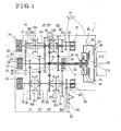
- Fig. 1 is a schematic view showing an overall construction of a dual clutch transmission according to an embodiment disclosed here;
- a second speed drive gear 52, a fourth speed drive gear 54 with larger diameter, and a sixth speed drive gear 56 are provided on the first input shaft 21.Further, a connection portion connected to the first clutch disc 44 of the dual clutch 40 is formed on the first input shaft 21 in a form of a spline.
- the second input shaft 22 which is a solid shaft, is rotatably supported by a ball bearing (i.e.,serving as the bearing) 23 relative to the transmission case 11. That is, the second input shaft 22 is arranged coaxially with the first input shalt 21to be penetrated through the first input shaft 21and to be relatively rotatable. Portions to support the bearings and plural external splines are formed on an external peripheral surface of the second input shaft 22. A first speed drive gear 51 and a third speed drive gear 53 having a larger diameter are directly formed on the second input shaft 22. A fifth speed drive gear 55 and a seventh speed drive gear 57 are fitted onto the external spline formed on the external peripheral surface of the second input shaft 22 by means of a spline engagement. Further, an end portion of the second input shaft 22 is formed with a connection portion connected to a second clutch disc 47 of the dual clutch 40 in a form of spline. A hollow shaft may, alternatively, be applied as the second input shaft 22.
- the first output shaft 31 is supported by the bearings 24, 27 to be rotatable relative to the transmission case 11 and the clutch housing 12, and is arranged in parallel to the second input shaft 22 in the transmission case 11.
- the final speed reduction drive gear 68, portions supporting the bearings and plural external splines are formed on an external peripheral surface of the first output shaft 31.
- Hubs 201 each provided for shift clutches 102, 104, respectively, are fitted to the external spline of the first output shaft 31 by means of spline fitting.
- the final speed reduction drive gear 68 is meshed with the ring gear 80 of a differential mechanism.
- the first output shaft 31 is formed with a support portion which idly supports a second speed driven gear 62, a fifth speed driven gear 65, a sixth speed driven gear 66, and a seventh speed driven gear 67.
- the second output shaft 32 is supported by the bearings 25, 28 to be rotatable relative to the transmission case 11 and the clutch housing 12, and is arranged in parallel with the second Input shaft 22 in the transmission case 11.
- the final speed reduction drive gear 58 is formed on an external peripheral surface of the second output shaft 32. Further, portions to support bearings and plural external splines are formed on the external peripheral surface of the second output shaft 32.
- the hub 201 for each shift clutch 101, 103 is press-fitted to the external spline of the second output shaft 32 by a spline engagement.
- the final speed reduction drive gear 58 is meshed with the ring gear 80 of the differential mechanism.
- the second output shaft 32 is formed with support portions which Idly support a first speed driven gear 61,a third speed driven gear 63, a fourth speed driven gear 64, and the reverse gear 70.
- the sleeve 202 When the sleeve 202 axially slides relative to the hub 201, the sleeve 202 is configured to engage with a synchromesh gear portion of the reverse gear 70 or one of the driven gears 61 to 67. Namely, by the sliding movement in the axial direction, the sleeve 202 switches an engaged state and a disengaged state with the synchromesh gear provided at the driven gears 61 to 67 and the reverse gear 70,to selectively connect one of the first speed driven gear 61, the third speed driven gear 63, the fourth speed driven gear 64, and the reverse gear 70 to the second output shaft 32 , or one of the second speed driven gear 62, the fifth speed driven gear 65, the sixth speed driven gear 66, and the seventh speed driven gear 67 to the first output shaft 31 .
- the ring gear 80 is engaged with the final speed reduction drive gear 58 and the final speed reduction drive gear 68 so as to be always rotatably connected to the first output shaft 31 and the second output shaft 32.
- the ring gear 80 is connected to driving wheels via a rotational shaft pivotally supported by the case 10 and the differential mechanism. That is, the ring gear 80 of the differential mechanism serves as a final gear for the transmission.
- a first pressure plate P1 is arranged on an axis close to an engine E/G.
- a first clutch disc CD1 is arranged coaxially to the first pressure plate P1.
- a center plate CP is arranged adjacent to the first clutch disc CD1 in an axial direction.
- a second clutch disc CD2 is arranged coaxially to the first clutch disc CD1 so that the center plate CP is sandwiched by the second clutch disc CD2 and the first clutch disc CD1.
- a second pressure plate P2 is arranged adjacent to the second clutch disc CD2 in the axial direction.
Landscapes
- Engineering & Computer Science (AREA)
- General Engineering & Computer Science (AREA)
- Mechanical Engineering (AREA)
- Mechanical Operated Clutches (AREA)
- Structure Of Transmissions (AREA)
Abstract
Description
- This disclosure generally relates to an automatic transmission including a dual dutch.
- A dual clutch transmission (DCT), which is an automatic transmission including a dual clutch which shifts gears at high speed by selecting one of two coaxially provided input shafts to engage and disengage the input shafts and an engine effectively at an appropriate timing, is know.
- For example,
EP16326B7A2 - Notwithstanding, according to the disclosure in Patent reference 1, only the intermediate pressure plate is mounted to the input shaft to support an output of the engine. Thus, a supporting strength of the intermediate pressure plate is low and the intermediate pressure plate may be deformed when one of the clutch discs presses the intermediate pressure plate axially in a direction of the input shaft. Further, the construction disclosed in Patent reference 1 is susceptible to an engine oscillation/vibration, and the intermediate pressure plate may oscillate. Consequently, a connection between the intermediate pressure plate and one of the clutch discs which rotatably connects to the intermediate pressure plate is not stabilized to generate a dragging, or the like, and thus the clutch discs may be partially worn and/or a shifting feeling may be deteriorated.
- A need thus exists for a dual clutch transmission which securely engages and disengages clutches with simple structures.
- In light of the foregoing, the disclosure provides a dual clutch transmission, which includes a first input shaft rotatably supported by a case, the first input shaft including a hollow, a second input shaft penetrating through the first input shaft on a common axis with the first input shaft to be supported by the case, and a dual clutch selectively transmitting a rotational driving force of a prime mover to the first input shaft or the second input shaft. The dual clutch includes a clutch frame including a first wall and a second wall which are rotatably supported on the first input shaft and are connected to each other while keeping a distance from each other in an axial direction of the first input shaft, the clutch frame being restricted from moving towards the prime mover, a first clutch disc provided between the first wall and the second wall to be movable in the axial direction, a first pressure plate provided between the first clutch disc and the second wall to be movable in the axial direction, a first operational mechanism moving the first pressure plate towards the first wall, a second clutch disc positioned closer to the prime mover relative to the second wall to be movable in the axial direction, a second pressure prate provided between the second clutch disc and the prime mover to be movable in the axial direction, and a second operational mechanism moving the second pressure plate towards the second wall.
- According to the disclosure, the clutch frame connected to the prime mover is rotatably supported by the first input shaft which has a larger diameter and high flexural rigidity. Further, because the clutch frame is formed by connecting the first wall and the second wall, the rigidity of the clutch frame per se is enhanced. According to the foregoing construction, even if the clutch frame and the first input shaft receive the oscillation of the prime mover, the oscillation (flexure) of the clutch frame and the first input shaft can be effectively restrained. Further, when the first clutch disc or the second clutch disc presses the first wall or the second wall, respectively, for establishing a rotatably connecting state, the pressing force applied to the first wall and the second wall can be effectively received by the clutch frame with high rigidity and by the first input shaft with high flexure rigidity, and thus there is no possibility that the first wall and/or the second wall are/is bent. Accordingly, there is no possibility of abrasion because of an unstable engagement between the first-wall and the first clutch disc or between the second wall and the second clutch disc, and the rotational force (torque) of the prime mover can be effectively transmitted to each of the input shafts.
- According to another aspect of the disclosure, the clutch frame is connected to the prime mover via an oscillation absorbing mechanism.
- According to the disclosure, because the clutch frame is connected to the prime mover via the oscillation absorbing mechanism, the oscillation (vibration) of the prime mover is restrained so as not be transmitted to the first wall or the second wall. Thus, the dual clutch can transmit the rotational force (torque) of the prime mover to each of the input shafts more effectively.
- According to further aspect of the disclosure,the first wall and the second wall of the clutch frame are rotatably supported on the first input shaft while being restricted not to move relative to the first input shaft in the axial direction towards the prime mover.
- According to the disclosure,the axial movement of the first wall and the second wall of the clutch frame supported by the first input shaft relative to the first input shaft towards the prime mover is restricted independently. Thus, the engagement between the first wall and the first clutch disc or between the second wall and the second clutch disc is not assumed to be unstable due to the undesired movement of the first wall or the second wall in the pressed direction even if the first clutch disc or the second clutch disc presses the first wall or the second wall. Accordingly, there is no possibility that the abrasion is generated at the engaging surfaces, and reliability is further enhanced.
- The foregoing and additional features and characteristics of this disclosure will become more apparent from the following detailed description considered with the reference to the accompanying drawings, wherein:
-
Fig. 1 is a schematic view showing an overall construction of a dual clutch transmission according to an embodiment disclosed here; and -
Fig. 2 is a schematic view of a dual clutch and a damper according to the embodiment disclosed here. - One embodiment of a dual clutch transmission according to the disclosure will be explained with reference to illustrations of drawing figures as follows.
- Referring to
Figs. 1 and2 , a construction of a dual clutch transmission (DCT) 1 will be explained. - As shown in
Fig. 1 , the dual clutch transmission 1 includes afirst input shaft 21, asecond input shaft 22, afirst output shaft 31, and asecond output shaft 32 which are disposed within a case10. Further, adual clutch 40,drive gears 51 to 57 for each of shift stages, a finial-speedreduction drive gears 58, 68, drivengears 61 to 67 for each of the shift stages, a reverse gear 70, and aring gear 80 are provided in thecase 10. - As shown in
Fig. 1 , thecase 10 includes atransmission case 11 and aclutch housing 12. Thetransmission case 11 pivotally supports shafts via bearings 23 to 25, respectively. Theclutch housing 12 is positioned to face an end surface of thetransmission case 11 and is fixed to thetransmission case 11 by bolts. The clutch housing 12 pivotally supports the shafts viabearings 26 to 28, respectively, and houses thedual clutch 40 therein. - The
first input shaft 21, which is a hollow shaft, is rotatably supported on a portion of an external peripheral surface (external periphery) of thesecond input shaft 22 via needle bearings (i.e.,serving as a bearing) 33 to 35, and is rotatably supported by a ball bearing 26 (i.e., serving as a bearing) relative to theclutch housing 12. Portions for supporting the bearings and plural external gears are formed on the external periphery of thefirst input shaft 21. A secondspeed drive gear 52, a fourth speed drive gear 54 with larger diameter, and a sixth speed drive gear 56 are provided on the first input shaft 21.Further, a connection portion connected to thefirst clutch disc 44 of thedual clutch 40 is formed on thefirst input shaft 21 in a form of a spline. - The
second input shaft 22, which is a solid shaft, is rotatably supported by a ball bearing (i.e.,serving as the bearing) 23 relative to thetransmission case 11. That is, thesecond input shaft 22 is arranged coaxially with the first input shalt 21to be penetrated through the first input shaft 21and to be relatively rotatable. Portions to support the bearings and plural external splines are formed on an external peripheral surface of thesecond input shaft 22. A firstspeed drive gear 51 and a thirdspeed drive gear 53 having a larger diameter are directly formed on thesecond input shaft 22. A fifthspeed drive gear 55 and a seventhspeed drive gear 57 are fitted onto the external spline formed on the external peripheral surface of thesecond input shaft 22 by means of a spline engagement. Further, an end portion of thesecond input shaft 22 is formed with a connection portion connected to asecond clutch disc 47 of thedual clutch 40 in a form of spline. A hollow shaft may, alternatively, be applied as thesecond input shaft 22. - The
first output shaft 31 is supported by thebearings transmission case 11 and theclutch housing 12, and is arranged in parallel to thesecond input shaft 22 in thetransmission case 11. The final speed reduction drive gear 68, portions supporting the bearings and plural external splines are formed on an external peripheral surface of thefirst output shaft 31.Hubs 201 each provided forshift clutches first output shaft 31 by means of spline fitting. The final speed reduction drive gear 68 is meshed with thering gear 80 of a differential mechanism. Further, thefirst output shaft 31 is formed with a support portion which idly supports a second speed drivengear 62, a fifth speed drivengear 65, a sixth speed drivengear 66, and a seventh speed drivengear 67. - The
second output shaft 32 is supported by thebearings transmission case 11 and theclutch housing 12, and is arranged in parallel with thesecond Input shaft 22 in thetransmission case 11. The final speedreduction drive gear 58 is formed on an external peripheral surface of thesecond output shaft 32. Further, portions to support bearings and plural external splines are formed on the external peripheral surface of thesecond output shaft 32. Thehub 201 for eachshift clutch second output shaft 32 by a spline engagement. The final speedreduction drive gear 58 is meshed with thering gear 80 of the differential mechanism. Further, thesecond output shaft 32 is formed with support portions which Idly support a first speed drivengear 61,a third speed drivengear 63, a fourth speed drivengear 64, and the reverse gear 70. - The reverse gear 70 is idly provided at the support portion of the reverse gear 70 formed on the
second output shaft 32. According to the embodiment, the reverse gear 70 is always engaged with a small diameter gear 62a which is integrally formed with the second speed drivengear 62. - Each of the
shift clutches 101, 102,103,104 includes thehub 201 and a sleeve202. Thehub 201 is formed in a disc shape having a hollow, which is formed with an internal spline and an external spline, and is fitted onto the external spline of thefirst output shaft 31, or thesecond output shaft 32 by means of the spline engagement. Thesleeve 202 is geared with the external spline of thehub 201 to be axially slidable relative to thehub 201. When thesleeve 202 axially slides relative to thehub 201, thesleeve 202 is configured to engage with a synchromesh gear portion of the reverse gear 70 or one of the driven gears 61 to 67. Namely, by the sliding movement in the axial direction, thesleeve 202 switches an engaged state and a disengaged state with the synchromesh gear provided at the driven gears 61 to 67 and the reverse gear 70,to selectively connect one of the first speed drivengear 61, the third speed drivengear 63, the fourth speed drivengear 64, and the reverse gear 70 to thesecond output shaft 32, or one of the second speed drivengear 62, the fifth speed drivengear 65, the sixth speed drivengear 66, and the seventh speed drivengear 67 to thefirst output shaft 31. - As shown in
Fig. 1 , thering gear 80 is engaged with the final speedreduction drive gear 58 and the final speed reduction drive gear 68 so as to be always rotatably connected to thefirst output shaft 31 and thesecond output shaft 32. Thering gear 80 is connected to driving wheels via a rotational shaft pivotally supported by thecase 10 and the differential mechanism. That is, thering gear 80 of the differential mechanism serves as a final gear for the transmission. - Constructions of the
dual clutch 40 will be explained in detail referring toFigs. 1 and2 as follows. Thedual clutch 40, which is a dry type clutch, includes aclutch frame 43, a firstclutch disc 44, afirst pressure plate 45, a firstoperational mechanism 46, a secondclutch disc 47, asecond pressure plate 48, and a secondoperational mechanism 49. The firstclutch disc 44 transmits a torque (rotational driving force) of an internal combustion engine (i.e.,serving as a prime mover) E/G to the first input shaft 21.The secondclutch disc 47 transmits a driving force of the internal combustion engine E/G to thesecond input shaft 22. - The
dual clutch 40 is housed in theclutch housing 12 at a right side inFig. 1 , and a rotational shaft of thedual clutch 40 is provided coaxially to thefirst input shaft 21 and the second-input shaft 22. The firstclutch disc 44 is spline fitted onto a connecting shaft portion of thefirst input shaft 21 to be axially movable while being restricted with a rotational movement. The secondclutch disc 47 is spline fitted onto a connecting shaft portion of thesecond input shaft 22 to be axially movable while being restricted with a rotational movement. According to thedual clutch 40, a high speed shift change is performed by switching the connections with the internal combustion engine E/G by consecutively operating the first and secondclutch discs second input shafts - The
clutch frame 43 is rotatably mounted on thefirst input shaft 21, and is rotatably connected to the internal combustion engine E/G while a rotational direction is limited, Thus, theclutch frame 43 integrally rotates with the internal combustion engine E/G. Theclutch frame 43 includes afirst wall 43a and asecond wall 43b which are connected to each other as shown inFig. 2 . Thefirst wall 43a and thesecond wall 43b are each formed in a disc shape. Thesecond wall 43b is positioned at a side closer to the internal combustion engine E/G keeping a predetermined distance from thefirst wall 43a in an axial direction on thefirst input shaft 21. Internal periphery portions of thefirst wall 43a and thesecond wall 43b are rotatably supported by bearings (e.g.,ball bearings) 41, 42, respectively. - End surfaces of the
bearings bearings first input shaft 21 towards the internal combustion engine E/Gin one axial direction of thefirst input shaft 21 is securely restricted. For example, a C-ring fitted into a groove formed on an external peripheral surface of thefirst input shaft 21 serves as thestopper plate stopper plates bearings stopper plate 82 may be provided, and adequate effects can be attained. Alternatively, only thestopper plate 81 may be provided. - Outer periphery portions of the
first wall 43a and thesecond wall 43b are connected by a connectingportion 43c, thus, by integrally forming thefirst wall 43a and thesecond wall 43b into a box shaped structure, theclutch frame 43 with high rigidity is attained. - The first
clutch disc 44 is a frictional plate formed in a disc shape. The firstclutch disc 44 is pressed onto a plane surface of thefirst wall 43a of theclutch frame 43 facing the internal combustion engine E/G to engage with-thefirst wall 43a by a frictional force so as to integrally rotate with thefirst wall 43a. The firstclutch disc 44 is positioned between thefirst wall 43a and thesecond wall 43b. A spline is formed on an internalperipheral portion 44a of the firstclutch disc 44. The spline of the firstclutch disc 44 is engaged with a spline formed on the external peripheral surface of thefirst input shaft 21, thereby restricting the rotation of the firstclutch disc 44 and allowing the movement of the firstclutch disc 44 in the axial direction. Accordingly, by the engagement of the firstclutch disc 44 with thefirst wall 43a (the clutch frame 43) to integrally rotate, a rotational force of the internal combustion engine E/G is transmitted to the firstclutch disc 44 via theclutch frame 43 and is transmitted to the first input shaft 21from the firstclutch disc 44. - The
first pressure plate 45 is configured to press the firstclutch disc 44 towards thefirst wall 43a in order to engage the firstclutch disc 44 with thefirst wall 43a. Thus, thefirst pressure plate 45 is positioned between the firstclutch disc 44 and thesecond wall 43b to be movable in the axial direction. Thefirst pressure plate 45 is formed in a disc plate shape, presses the firstclutch disc 44 towards thefirst wall 43a by means of the firstoperational mechanism 46, and sandwiches the firstclutch disc 44 together with thefirst wall 43a. Thefirst pressure plate 45 is supported by the firstoperational mechanism 46. - The first
operational mechanism 46 is configured to press the firstclutch disc 44 towards thefirst wall 43a via thefirst pressure plate 45 to move the firstclutch disc 44 forward or backward. The firstoperational mechanism 46 includes alink portion 71 and acylinder portion 72, Thelink portion 71 includes a lever mechanism having alever 71a, aconnection lever 71d, and aprojection portion 77. - The
projection portion 77 supporting afulcrum 71e of thelever 71 a is formed on a wall surface of thefirst wall 43a facing the transmission. Anapplication point portion 71b of force of thelever 71a serving as a point of application of the lever mechanism is connected to thefirst pressure plate 45 by theconnection lever 71d. A tip end of acylinder piston 72b of acylinder 72a of thecylinder portion 72 is attachable to and detachable from a point ofeffort portion 71c of thelever 71a (i.e., serving as a point of effort of the lever).The connection lever71d is supported by thefirst wall 43a by means of a plate shaped spring member which restricts a rotational movement and allows a linear movement of theconnection lever 71d in an axial direction. Thus, thelink portion 71 including theconnection lever 71d and thefirst pressure plate 45 connected to theconnection lever 71d are integrally rotated with thefirst wall 43a. - The
cylinder portion 72 includes an electric motor supported by theclutch housing 12 and thecylinder 72a. The electric motor converts a rotational movement to a linear movement to move the tip end of thecylinder piston 72b of thecylinder 72a in a forward or backward direction. Then, by pressing the point ofeffort portion 71 c of thelever 71a by the tip end of thecylinder piston 72b towards the internal combustion E/G, thefirst pressure plate 45 is moved towards thefirst wall 43a to press the firstclutch disc 44 in the axial direction so that the firstclutch disc 44 and thefirst wall 43a are engaged. - The second
clutch disc 47 is a frictional plate formed in a disc shape. The secondclutch disc 47 is pressed onto a plane surface of thesecond wall 43b of theclutch frame 43 facing the internal combustion engine E/G to engage with thesecond wall 43b by a frictional force so as to integrally rotate with thesecond wall 43b. The secondclutch disc 47 is positioned closer to the internal combustion engine E/G relative to thesecond wall 43b. A spline is formed on an internalperipheral portion 47a of the secondclutch disc 47. The spline of the secondclutch disc 47 is engaged with a spline formed on the external peripheral surface of thesecond input shaft 22, thereby restricting the rotation of the secondclutch disc 47 and allowing the movement of the secondclutch disc 47 in the axial direction. Accordingly, by the engagement of the secondclutch disc 47 with thesecond wall 43b (the clutch frame 43) to integrally rotate, a rotational force of the internal combustion engine E/G is transmitted to the secondclutch disc 47 via theclutch frame 43 and is transmitted to thesecond input shaft 22 from the secondclutch disc 47. - The
second pressure plate 48 is configured to press the secondclutch disc 47 towards thesecond wall 43b in order to engage the secondclutch disc 47 with thesecond wall 43b. Thus, thesecond pressure plate 48 is positioned closer to the internal combustion engine E/G relative to the secondclutch disc 47 to be movable in the axial direction. Thesecond pressure plate 48 is formed in a disc plate shape, presses the secondclutch disc 47 towards thesecond wall 43b by means of the secondoperational mechanism 49, and sandwiches the secondclutch disc 47 together with thesecond wall 43b. Thesecond pressure plate 46 is supported by the secondoperational mechanism 49. - The second
operational mechanism 49 is configured to press the secondclutch disc 47 towards thesecond wall 43b via thesecond pressure plate 48 to move the secondclutch disc 47 forward or backward. The secondoperational mechanism 49 includes alink portion 73 and a cylinder portion74.Thelink portion 73 includes a lever mechanism having alever 73a,connection lever 73d, and aprojection portion 78. - The
projection portion 78 supporting afulcrum 73e of thelever 73a is formed on a wall surface of thefirst wall 43a facing the transmission. Anapplication point portion 73b of force of thelever 73a serving as a point of application of the lever mechanism is connected to thesecond pressure plate 48 by the connection lever73d. A tip end of acylinder piston 74b of acylinder 74a of thecylinder portion 74 is attachable to and detachable from a point ofeffort portion 73c of thelever 73a (i.e., serving as a point of effort of the lever). Theconnection lever 73d is supported by thesecond wall 43b by means of a plate shaped spring member which restricts a rotational movement and allows a linear movement of theconnection lever 73d in an axial direction. Thus, thelink portion 73 including theconnection lever 73d and thesecond pressure plate 48 connected to theconnection lever 73d are integrally rotated with thesecond wall 43b. - The
cylinder portion 74 includes an electric motor supported by theclutch housing 12 and thecylinder 74a. The electric motor converts a rotational movement to a linear movement to move the tip end of thecylinder piston 74b of thecylinder 74a in a forward or backward direction. Then, by pressing the point ofeffort portion 73c of thelever 73a by the tip end of thecylinder piston 74b towards the internal combustion E/G, thesecond pressure plate 48 is moved towards thesecond wall 43b to press the secondclutch disc 47 in the axial direction so that the secondclutch disc 47 and thesecond wall 43b are engaged. - The
clutch frame 43 is connected to anoutput shaft 13 of the internal combustion engine E/G via aflywheel 94, adamper 75 serving as an oscillation absorbing mechanism, and a connectingarm 76. As shown inFig. 2 , thedamper 75 is arranged between the connectingarm 76 and theflywheel 94 in order to absorb oscillations generated in an axial direction and an orthogonal direction relative to the output shaft of the internal combustion engine E/G.A coil spring 75a is compressingly in contact with thedamper 75 so that a neutral position at theclutch frame 43 side is maintained by a reaction force of thecoil spring 75a. When a vibration (oscillation) in a rotational direction is transmitted from the internal combustion engine E/G, thecoil spring 75a is compressed to absorb the vibration, and thecoil spring 75a returns to an original state when the vibration converges to restore theclutch frame 43 side to be in the neutral state. Further, when the vibration in a rotational axis direction is generated, the vibration is absorbed by a play for assembling thedamper 75. Thus, the vibration is absorbed by thedamper 75 even if the vibration is generated at the internal combustion engine E/G in the axial direction and in the orthogonal direction, theclutch frame 43 is unlikely influenced by the vibration and the vibration (oscillation) is not generated at thefirst wall 43a and thesecond wall 43b of theclutch frame 43. Accordingly, thefirst wall 43a and thesecond wall 43b, and the firstclutch disc 44 and the secondclutch disc 47 are favorably engaged without oscillation, - An operation of the dual clutch type transmission according to the embodiment will be explained hereinafter. When the dual clutch transmission 1 starts operating, a controlling device operates the first and second
clutch discs dual clutch 40 and theshift clutches 101 to 104 in accordance with vehicle operational states, for example, a throttle opening degree, an engine rotation speed, and a vehicle speed. In a state where the dual clutch transmission 1 is not operated, the first and secondclutch discs dual clutch 40 are disengaged and theshift clutches 101 to 104 are positioned at each of the neutral positions. - First, when the internal combustion engine E/G is started in a state where a vehicle stops and a shift lever of the dual clutch transmission 1 is shifted to a forward position for moving a vehicle forward, the control device slides the
sleeve 202 of theshift clutch 101 to engage thesleeve 202 with the synchromesh gear portion of the drivengear 61 of the speed gears, and controls other clutches to be at the neutral portions to establish a gear arrangement for a first speed gear stage. When a rotation speed of the internal combustion engine E/G exceeds a predetermined speed upon an increase in the throttle opening degree, the control device operates the secondclutch disc 47 of the dual clutch 40 in accordance with the level of throttle opening degree to gradually increase an engaging force so that the secondclutch disc 47 is rotatably connected to thesecond input shaft 22 and thesecond output shaft 32 including the first speed gear set 51, 61. - In those circumstances, the control device operates the electric motor of the second
operational mechanism 49 to operate the secondclutch disc 47, thus to move thecylinder piston 74b of thecylinder portion 74 in a forward direction, that is, towards the internal combustion engine E/G. Thereafter, the control device controls to contact the tip end of thecylinder piston 74b to the point ofeffort portion 73c of thelever 73a of thelink portion 73 and further moves thecylinder piston 74b forward. Thelever 73a whose point of effort (i.e., the point ofeffort portion 73c) is pressed towards the internal combustion engine E/G rotates about a fulcrum (i.e., the projection portion 78) provided at thefirst wall 43a so that the point ofapplication portion 73b moves to be away from thefirst wall 43a. Because the point ofapplication portion 73b is connected to the second pressure plate 4B by means of theconnection lever 73d, the movement of the point of application portion being away from thefirst wall 43a allows thesecond pressure plate 48 to move towards thesecond wall 43b, and thesecond pressure plate 48 pushes the secondclutch disc 47 towards thesecond wall 43b. By further moving thecylinder piston 74b in the forward direction, the secondclutch disc 47 is pressed to thesecond wall 43b and is positioned between thesecond pressure plate 48 and thesecond wall 43b to integrally rotate. Then, the rotational force of the internal combustion engine E/G is transmitted to thesecond input shaft 22 to which the secondclutch disc 47 is rotatably connected. - In those circumstance, the
second wall 43b, which is pressed by the secondclutch disc 47, is integrally connected to thefirst wall 43a to form theclutch frame 43 to have high rigidity, and is mounted to thefirst input shaft 21, which has a larger diameter and a higher rigidity than thesecond input shaft 22, via thebearings first wall 43a. Accordingly, because theclutch frame 43 and thefirst input shaft 21 stably support thesecond wall 43b without bending even if thesecond wall 43b is pushed by the secondclutch disc 47, there is no possibility of abrasion due to an undesired partial contact of the secondclutch disc 47 to thesecond wall 43b because of an unstable engagement between the secondclutch disc 47 and thesecond wall 43b. - Accordingly, the driving force of the internal combustion engine E/G is transmitted from the
second wall 43b (clutch frame 43) to thering gear 80 of the differential mechanism via the secondclutch disc 47, thesecond input shaft 22, the first speed gear set 51, 61, theshift clutch 101, thesecond output shaft 32, and the final speedreduction driving gear 58, in the mentioned order, and thus the vehicle travels in the first speed. - Next, when the vehicle operational state is assumed to be a state which is appropriate for a second-speed traveling, for example, by an increase of the throttle opening degree, the control device slides the
sleeve 202 of theshift clutch 102 to engage thesleeve 202 with the synchromesh gear portion of the drivengear 62 of the speed gears to establish a gear arrangement for a second speed gear stage. Then, thedual clutch 40 is switched to the firstclutch disc 44 to switch to a second speed traveling, and thesleeve 202 of theshift clutch 101 is disengaged thereafter. - In those circumstances, the control device activates the electric motor of the first
operational mechanism 46 in order to switch the dual clutch 40 to connect the firstclutch disc 44, and controls thecylinder piston 72b of thecylinder portion 72 to move forward towards the internal combustion engine E/G. Then, the control device controls thecylinder piston 72b so that the tip end thereof contacts the point ofeffort portion 71c of thelever 71a of thelink portion 71 and thecylinder piston 72b further moves forward. Thelever 71a whose point of effort (i.e., the point ofeffort portion 71c) is pressed towards the internal combustion engine E/G rotates about a fulcrum-(i.e., the projection portion 77) provided at thefirst wall 43a so that the point ofapplication portion 71 b moves to be away from thefirst wall 43a. Because the point ofapplication portion 71 b is connected to thefirst pressure plate 45 by means of theconnection lever 71d, the movement of the point ofapplication portion 71 b being away from thefirst wall 43a allows thefirst pressure plate 45 to move towards thefirst wall 43a, and thefirst pressure plate 45 pushes the firstclutch disc 44 towards thefirst wall 43a. By further moving thecylinder piston 72b in the forward direction, the firstclutch disc 44 is pressed to thefirst wall 43a and is positioned between thefirst pressure plate 45 and thefirst wall 43a to integrally rotate. Then, the rotational force of the internal combustion engine E/G is transmitted to thefirst input shaft 21 to which the firstclutch disc 44 is rotatably connected. - In those circumstances, similar to the operation of the second
clutch disc 47, because theclutch frame 43 and thefirst input shaft 21 stably support thefirst wall 43a without bending even if thefirst wall 43a is pushed by the firstclutch disc 44, there is no possibility of abrasion due to an undesired partial contact of the firstclutch disc 44 to thefirst wall 43a because of an unstable engagement between the firstclutch disc 44 and thefirst wall 43a. - Accordingly, the driving force of the internal combustion engine E/G is transmitted from the
first wall 43a (clutch frame 43) to thering gear 80 of the differential mechanism via the firstclutch disc 44, thefirst input shaft 21, the second speed gear set 52, 62, theshift clutch 102, thefirst output shaft 31, and the final speed reduction driving gear 68, in the mentioned order, and thus the vehicle travels in the second speed. - Similar to the foregoing operations, in the third speed to the seventh speed, the control device controls to consecutively select speed gears appropriate for the operational state of the vehicle, and selects the first
clutch disc 44 and the secondclutch disc 47 alternately, so that the vehicle travels with the selection of a speed gear which is appropriate for the traveling state, - When the shift lever of the dual clutch transmission 1 is shifted to a reverse position in a state where the vehicle stops while the engine E/G is running, the control device detects that the shift lever is at the reverse position and slides the
sleeve 202 of the shift dutch 103 to engage thesleeve 202 with the synchromesh gear portion of the reverse gear 70, and controls other clutches to be at the neutral portions to establish a gear arrangement for a reverse gear stage. In those circumstances, the reverse gear 70 is always engaged with the small diameter gear 62a which is integrally formed with the drivengear 62 of the speed gears. Then, as explained above, when the reverse gear 70 is selected, the firstclutch disc 44 is selected to connect to thefirst input shaft 21. Accordingly, the driving force of the internal combustion engine E/G is transmitted from thefirst wall 43a (clutch frame 43) to thering gear 80 of the differential mechanism via the firstclutch disc 44, thefirst input shaft 21, the second speed gear set 62, 62, 62a, the reverse gear 70, theshift clutch 103, thesecond output shaft 32, and the final speedreduction driving gear 58, in the mentioned order, and thus the vehicle starts moving in a reverse direction. - As explained above, according to the embodiment, the
clutch frame 43 rotatably connected to the internal combustion engine E/G serving as the prime mover is supported by thefirst input shaft 21 which has a large diameter and has a high flexural rigidity. Further, because theclutch frame 43 is formed by connecting thefirst wall 43a and thesecond wall 43b, a strength/rigidity of theclutch frame 43 per se is enhanced. Accordingly, even if theclutch frame 43 and thefirst input shaft 21 receive the oscillation of the internal combustion engine E/G, the oscillation (flexure) of theclutch frame 43 and thefirst input shaft 21 is effectively restrained. Further, because thefirst wall 43a or thesecond wall 43b effectively receives the pressing force as theclutch frame 43 having high rigidity and by thefirst input shaft 21 having high flexural rigidity when the firstclutch disc 44 or the secondclutch disc 47 is rotatably connected while pressing thefirst wall 43a or thesecond wall 43b, there is no possibility that thefirst wall 43a or thesecond wall 43b is bent. Accordingly, there is no possibility of abrasion at the engaging surfaces of the clutch disc and the wall because of an unstable engagement between thefirst wall 43a and the firstclutch disc 44 or between the secondclutch disc 47 and thesecond wall 43b, and thus the rotational force of the internal combustion engine E/G can be effectively transmitted to theinput shafts - Further, according to the construction of the embodiment, because the
clutch frame 43 is rotatably connected to the internal combustion engine E/G via thedamper 75 serving as the oscillation absorbing mechanism, the oscillation (vibration) of the internal combustion engine E/G is restrained and is not transmitted to thefirst wall 43a and/or thesecond wall 43b. Accordingly, the dual clutch 40 transmits the rotational force (torque) of the internal combustion E/G to each of theinput shafts - According to a known construction, for example, shown in
Fig. 3 , a first pressure plate P1 is arranged on an axis close to an engine E/G. A first clutch disc CD1 is arranged coaxially to the first pressure plate P1. A center plate CP is arranged adjacent to the first clutch disc CD1 in an axial direction. A second clutch disc CD2 is arranged coaxially to the first clutch disc CD1 so that the center plate CP is sandwiched by the second clutch disc CD2 and the first clutch disc CD1. A second pressure plate P2 is arranged adjacent to the second clutch disc CD2 in the axial direction. When a torque is transmitted, the first clutch disc CD1 and the second clutch disc CD2 are pressed to contact the first pressure plate P1 and the second pressure plate P2, respectively, and to contact the center plate CP. In those circumstance, the both side surfaces of the first clutch disc CD1 and the both side surfaces of the second clutch disc CD2 are heated by a frictional contact with the first pressure plate P1 and the second pressure plate P2, respectively, and with the center plate CP, thus, a torque is not stabilized. On the other hand, according to the construction of the embodiment, as shown inFig. 2 , a portion of the flrstclutch disc 44 pressed by thefirst pressure plate 45 corresponds to one side surface of the firstclutch disc 44, and a portion of the secondclutch disc 47 pressed by thesecond pressure plate 48 corresponds to one side surface of the secondclutch disc 47. Further thefirst pressure plate 45 and thesecond wall 43b are positioned keeping a predetermined length of distance therebetween. Thus, the firstclutch disc 44 and the secondclutch disc 47 are not affected by the heat generated due to being pressed on the both side surfaces thereof. Accordingly, a frictional coefficient of the firstclutch disc 45 and the secondclutch disc 47 can be estimated with high precision, and the torque is stabilized. - According to the embodiment, a frictional plate with a single plate is applied as the first
clutch disc 44 and the secondclutch disc 47. However, the construction of the firstclutch disc 44 and the secondclutch disc 47 is not limited, and any types of multiple plate clutches with multiple frictional plates are applicable. Namely, for example, multiple clutch discs and multiple movable bodies are arranged alternately so that each of the movable bodies is positioned between the adjacent clutch discs to be pressed by a pressure plate. The same effects and advantage from the embodiment can be attained with this structure. - According to the embodiment, the internal combustion engine E/G is applied as the prime mover, the construction of the prime mover is not limited. For example, an electric motor may be applied.
- According to the embodiment, the
cylinder portions clutch disc 44 and the secondclutch disc 47 are driven by the electric motor, however, the construction for actuating thecylinder portions - Further, according to the embodiment, the dual clutch transmission is applied to an automobile, however, the dual clutch transmission of the disclosure is applicable to other vehicles, for example, ships, boats, trains, and aircrafts.
It is explicitly stated that all features disclosed in the description and/or the claims are intended to be disclosed separately and independently from each other for the purpose of original disclosure as well as for the purpose of restricting the claimed invention independent of the composition of the features in the embodiments and/or the claims. It is explicitly stated that all value ranges or indications of groups of entities disclose every possible intermediate value or intermediate entity for the purpose of original disclosure as well as for the purpose of restricting the claimed invention, in particular as limits of value ranges.
Claims (4)
- A dual clutch transmission, comprising:a first input shaft (21) rotatably supported by a case (10), the first input shaft (21) including a hollow;a second input shaft (22) penetrating through the first input shaft (21) on a common axis with the first input shaft (21) to be supported by the case;a dual clutch (40) selectively transmitting a rotational driving force of a prime mover (E/G) to the first input shaft (21) or the second input shaft (22), the dual clutch (40) including:a clutch frame (43) including a first wall (43a) and a second wall (43b) which are rotatably supported on the first input shaft (21) and are connected to each other while keeping a distance from each other in an axial direction of the first input shaft (21), the clutch frame (43) being restricted from moving towards the prime mover;a first clutch disc (44) provided between the first wall (43a) and the second wall (43b) to be movable in the axial direction;a first pressure plate (45) provided between the first clutch disc (44) and the second wall (43b) to be movable in the axial direction;a first operational mechanism (46) moving the first pressure plate (45) towards the first wall (43a);a second clutch disc (47) positioned closer to the prime mover relative to the second wall (43b) - to be movable in the axial direction;a second pressure plate (48) provided between the second clutch disc (47) and the prime mover to be movable in the axial direction; anda second operational mechanism (49) moving the second pressure plate (48) towards the second wall (43b).
- The dual clutch transmission according to claim 1, wherein the clutch frame (43) is connected to the prime mover (E/G) via an oscillation absorbing mechanism (75).
- The dual clutch transmission according to either claim 1 or 2, wherein the first wall (43a) and the second wall (43b) of the clutch frame (43) are rotatably supported on the first input shaft (21) while being restricted not to move relative to the first input shaft in the axial direction towards the prime mover (E/G).
- The dual clutch transmission according to claim 3 further comprising:at least one restriction member (81, 82) provided on the first input shaft for restricting the clutch frame (43) from moving towards the prime mover (E/G).
Applications Claiming Priority (1)
| Application Number | Priority Date | Filing Date | Title |
|---|---|---|---|
| JP2010246881A JP5528302B2 (en) | 2010-11-02 | 2010-11-02 | Dual clutch automatic transmission |
Publications (4)
| Publication Number | Publication Date |
|---|---|
| EP2447560A2 true EP2447560A2 (en) | 2012-05-02 |
| EP2447560A3 EP2447560A3 (en) | 2013-06-19 |
| EP2447560B1 EP2447560B1 (en) | 2014-06-11 |
| EP2447560B8 EP2447560B8 (en) | 2014-07-16 |
Family
ID=44862809
Family Applications (1)
| Application Number | Title | Priority Date | Filing Date |
|---|---|---|---|
| EP11187259.4A Not-in-force EP2447560B8 (en) | 2010-11-02 | 2011-10-31 | Dual clutch transmission |
Country Status (3)
| Country | Link |
|---|---|
| EP (1) | EP2447560B8 (en) |
| JP (1) | JP5528302B2 (en) |
| CN (1) | CN102562844B (en) |
Cited By (2)
| Publication number | Priority date | Publication date | Assignee | Title |
|---|---|---|---|---|
| CN104482172A (en) * | 2014-12-18 | 2015-04-01 | 重庆隆旺机电有限责任公司 | Double-clutch transmission |
| CN111059168A (en) * | 2020-01-08 | 2020-04-24 | 尚尔航 | Lever-controlled clutch and speed-changing device |
Families Citing this family (3)
| Publication number | Priority date | Publication date | Assignee | Title |
|---|---|---|---|---|
| KR101745157B1 (en) | 2015-10-26 | 2017-06-08 | 현대자동차주식회사 | Method for controlling driving of vehicles |
| CN112744065B (en) * | 2019-10-30 | 2022-10-18 | 比亚迪股份有限公司 | Hybrid power system and vehicle with same |
| CN112747112B (en) * | 2019-10-30 | 2022-05-13 | 比亚迪股份有限公司 | Clutch, transmission, power system and vehicle |
Citations (1)
| Publication number | Priority date | Publication date | Assignee | Title |
|---|---|---|---|---|
| EP1632687A2 (en) | 2004-09-03 | 2006-03-08 | LuK Lamellen und Kupplungsbau Beteiligungs KG | Torque transmission device |
Family Cites Families (10)
| Publication number | Priority date | Publication date | Assignee | Title |
|---|---|---|---|---|
| GB1517516A (en) * | 1974-11-27 | 1978-07-12 | Automotive Prod Co Ltd | Clutches |
| JPH08320054A (en) * | 1995-05-24 | 1996-12-03 | Toyota Motor Corp | Gear type transmission |
| DE10134118B4 (en) * | 2001-07-13 | 2013-02-21 | Volkswagen Ag | Double coupling |
| DE102004001278B4 (en) * | 2004-01-07 | 2015-08-13 | Volkswagen Ag | Double clutch transmission for a motor vehicle |
| DE102006045163A1 (en) * | 2006-09-25 | 2008-04-03 | Robert Bosch Gmbh | Double clutch for a dual-clutch transmission |
| DE102007047671A1 (en) * | 2007-10-05 | 2009-04-09 | Daimler Ag | Dual clutch transmission device |
| DE102009002351B4 (en) * | 2009-04-14 | 2019-10-10 | Zf Friedrichshafen Ag | Double clutch |
| US8302500B2 (en) * | 2009-04-22 | 2012-11-06 | GM Global Technology Operations LLC | Dual clutch transmission |
| KR101132458B1 (en) * | 2009-04-24 | 2012-03-30 | 강명구 | Multiple-clutch Transmission with dual front-positioned gears |
| CN201502668U (en) * | 2009-07-21 | 2010-06-09 | 上海汽车集团股份有限公司 | dual clutch transmission |
-
2010
- 2010-11-02 JP JP2010246881A patent/JP5528302B2/en not_active Expired - Fee Related
-
2011
- 2011-10-31 EP EP11187259.4A patent/EP2447560B8/en not_active Not-in-force
- 2011-11-02 CN CN201110344212.8A patent/CN102562844B/en not_active Expired - Fee Related
Patent Citations (1)
| Publication number | Priority date | Publication date | Assignee | Title |
|---|---|---|---|---|
| EP1632687A2 (en) | 2004-09-03 | 2006-03-08 | LuK Lamellen und Kupplungsbau Beteiligungs KG | Torque transmission device |
Cited By (2)
| Publication number | Priority date | Publication date | Assignee | Title |
|---|---|---|---|---|
| CN104482172A (en) * | 2014-12-18 | 2015-04-01 | 重庆隆旺机电有限责任公司 | Double-clutch transmission |
| CN111059168A (en) * | 2020-01-08 | 2020-04-24 | 尚尔航 | Lever-controlled clutch and speed-changing device |
Also Published As
| Publication number | Publication date |
|---|---|
| JP2012097852A (en) | 2012-05-24 |
| EP2447560B1 (en) | 2014-06-11 |
| JP5528302B2 (en) | 2014-06-25 |
| CN102562844A (en) | 2012-07-11 |
| EP2447560B8 (en) | 2014-07-16 |
| EP2447560A3 (en) | 2013-06-19 |
| CN102562844B (en) | 2015-12-09 |
Similar Documents
| Publication | Publication Date | Title |
|---|---|---|
| US8156837B2 (en) | Multiple-ratio transmission with concentric offset shift forks | |
| JP5789508B2 (en) | Synchronous lock clutch-combination of friction clutch and mechanical locking clutch | |
| EP2405162B1 (en) | Park lock apparatus for a transmission | |
| EP2738421B1 (en) | Transmission and electric vehicle comprising same | |
| EP2447560B1 (en) | Dual clutch transmission | |
| JP5145185B2 (en) | Power transmission device | |
| CN107407378B (en) | Dual Countershaft Transmission with Splines | |
| JP5303318B2 (en) | Power transmission device | |
| KR101103969B1 (en) | DCT clutch actuator | |
| KR20090021263A (en) | Gearshift Interlock | |
| KR20100066373A (en) | Compact dry dual clutch module | |
| JPH0792115B2 (en) | Dual mass flywheel | |
| EP2110578A2 (en) | Dual clutch type automated transmission apparatus | |
| KR101647529B1 (en) | Dual clutch mechanism including a dual fork control device | |
| JP6699353B2 (en) | transmission | |
| CN219263108U (en) | A two-speed gearbox for electric vehicles using dual clutches | |
| JPH1037977A (en) | Gearbox prevention device for transmission | |
| CN111536210A (en) | Transmission, double-clutch mechanism and two-gear bridge driving system | |
| CN112923033A (en) | Compact torque transmission device for motor vehicle | |
| KR100597351B1 (en) | Manual transmission for rear wheel drive | |
| JP2003278808A (en) | Automatic transmission | |
| KR102089304B1 (en) | Gear unit | |
| JP2011127660A (en) | Shift operating device of automatic transmission | |
| KR102469747B1 (en) | Dual clutch device | |
| JP2003269609A (en) | Transmission for vehicles |
Legal Events
| Date | Code | Title | Description |
|---|---|---|---|
| PUAI | Public reference made under article 153(3) epc to a published international application that has entered the european phase |
Free format text: ORIGINAL CODE: 0009012 |
|
| AK | Designated contracting states |
Kind code of ref document: A2 Designated state(s): AL AT BE BG CH CY CZ DE DK EE ES FI FR GB GR HR HU IE IS IT LI LT LU LV MC MK MT NL NO PL PT RO RS SE SI SK SM TR |
|
| AX | Request for extension of the european patent |
Extension state: BA ME |
|
| PUAL | Search report despatched |
Free format text: ORIGINAL CODE: 0009013 |
|
| AK | Designated contracting states |
Kind code of ref document: A3 Designated state(s): AL AT BE BG CH CY CZ DE DK EE ES FI FR GB GR HR HU IE IS IT LI LT LU LV MC MK MT NL NO PL PT RO RS SE SI SK SM TR |
|
| AX | Request for extension of the european patent |
Extension state: BA ME |
|
| RIC1 | Information provided on ipc code assigned before grant |
Ipc: F16D 21/06 20060101AFI20130513BHEP |
|
| GRAP | Despatch of communication of intention to grant a patent |
Free format text: ORIGINAL CODE: EPIDOSNIGR1 |
|
| 17P | Request for examination filed |
Effective date: 20131015 |
|
| RBV | Designated contracting states (corrected) |
Designated state(s): AL AT BE BG CH CY CZ DE DK EE ES FI FR GB GR HR HU IE IS IT LI LT LU LV MC MK MT NL NO PL PT RO RS SE SI SK SM TR |
|
| INTG | Intention to grant announced |
Effective date: 20131126 |
|
| GRAS | Grant fee paid |
Free format text: ORIGINAL CODE: EPIDOSNIGR3 |
|
| GRAA | (expected) grant |
Free format text: ORIGINAL CODE: 0009210 |
|
| RAP1 | Party data changed (applicant data changed or rights of an application transferred) |
Owner name: EXEDY CORPORATION Owner name: AISIN SEIKI KABUSHIKI KAISHA |
|
| AK | Designated contracting states |
Kind code of ref document: B1 Designated state(s): AL AT BE BG CH CY CZ DE DK EE ES FI FR GB GR HR HU IE IS IT LI LT LU LV MC MK MT NL NO PL PT RO RS SE SI SK SM TR |
|
| REG | Reference to a national code |
Ref country code: GB Ref legal event code: FG4D |
|
| REG | Reference to a national code |
Ref country code: CH Ref legal event code: EP |
|
| REG | Reference to a national code |
Ref country code: DE Ref legal event code: R082 Ref document number: 602011007562 Country of ref document: DE Representative=s name: KRAMER BARSKE SCHMIDTCHEN PATENTANWAELTE PARTG, DE Ref country code: DE Ref legal event code: R082 Ref document number: 602011007562 Country of ref document: DE Representative=s name: KRAMER - BARSKE - SCHMIDTCHEN, DE |
|
| RIN2 | Information on inventor provided after grant (corrected) |
Inventor name: KUMIKAWA, YUKI Inventor name: TANAKA, SATOSHI Inventor name: NAGASAKA, HIROYUKI Inventor name: TOMITA, YUSUKE Inventor name: MORI, KYOSUKE |
|
| REG | Reference to a national code |
Ref country code: IE Ref legal event code: FG4D |
|
| REG | Reference to a national code |
Ref country code: AT Ref legal event code: REF Ref document number: 672419 Country of ref document: AT Kind code of ref document: T Effective date: 20140715 |
|
| REG | Reference to a national code |
Ref country code: DE Ref legal event code: R096 Ref document number: 602011007562 Country of ref document: DE Effective date: 20140724 |
|
| PG25 | Lapsed in a contracting state [announced via postgrant information from national office to epo] |
Ref country code: GR Free format text: LAPSE BECAUSE OF FAILURE TO SUBMIT A TRANSLATION OF THE DESCRIPTION OR TO PAY THE FEE WITHIN THE PRESCRIBED TIME-LIMIT Effective date: 20140912 Ref country code: LT Free format text: LAPSE BECAUSE OF FAILURE TO SUBMIT A TRANSLATION OF THE DESCRIPTION OR TO PAY THE FEE WITHIN THE PRESCRIBED TIME-LIMIT Effective date: 20140611 Ref country code: FI Free format text: LAPSE BECAUSE OF FAILURE TO SUBMIT A TRANSLATION OF THE DESCRIPTION OR TO PAY THE FEE WITHIN THE PRESCRIBED TIME-LIMIT Effective date: 20140611 Ref country code: NO Free format text: LAPSE BECAUSE OF FAILURE TO SUBMIT A TRANSLATION OF THE DESCRIPTION OR TO PAY THE FEE WITHIN THE PRESCRIBED TIME-LIMIT Effective date: 20140911 |
|
| REG | Reference to a national code |
Ref country code: NL Ref legal event code: VDEP Effective date: 20140611 |
|
| REG | Reference to a national code |
Ref country code: AT Ref legal event code: MK05 Ref document number: 672419 Country of ref document: AT Kind code of ref document: T Effective date: 20140611 |
|
| REG | Reference to a national code |
Ref country code: LT Ref legal event code: MG4D |
|
| PG25 | Lapsed in a contracting state [announced via postgrant information from national office to epo] |
Ref country code: LV Free format text: LAPSE BECAUSE OF FAILURE TO SUBMIT A TRANSLATION OF THE DESCRIPTION OR TO PAY THE FEE WITHIN THE PRESCRIBED TIME-LIMIT Effective date: 20140611 Ref country code: SE Free format text: LAPSE BECAUSE OF FAILURE TO SUBMIT A TRANSLATION OF THE DESCRIPTION OR TO PAY THE FEE WITHIN THE PRESCRIBED TIME-LIMIT Effective date: 20140611 Ref country code: HR Free format text: LAPSE BECAUSE OF FAILURE TO SUBMIT A TRANSLATION OF THE DESCRIPTION OR TO PAY THE FEE WITHIN THE PRESCRIBED TIME-LIMIT Effective date: 20140611 Ref country code: RS Free format text: LAPSE BECAUSE OF FAILURE TO SUBMIT A TRANSLATION OF THE DESCRIPTION OR TO PAY THE FEE WITHIN THE PRESCRIBED TIME-LIMIT Effective date: 20140611 |
|
| PG25 | Lapsed in a contracting state [announced via postgrant information from national office to epo] |
Ref country code: EE Free format text: LAPSE BECAUSE OF FAILURE TO SUBMIT A TRANSLATION OF THE DESCRIPTION OR TO PAY THE FEE WITHIN THE PRESCRIBED TIME-LIMIT Effective date: 20140611 Ref country code: SK Free format text: LAPSE BECAUSE OF FAILURE TO SUBMIT A TRANSLATION OF THE DESCRIPTION OR TO PAY THE FEE WITHIN THE PRESCRIBED TIME-LIMIT Effective date: 20140611 Ref country code: CZ Free format text: LAPSE BECAUSE OF FAILURE TO SUBMIT A TRANSLATION OF THE DESCRIPTION OR TO PAY THE FEE WITHIN THE PRESCRIBED TIME-LIMIT Effective date: 20140611 Ref country code: PT Free format text: LAPSE BECAUSE OF FAILURE TO SUBMIT A TRANSLATION OF THE DESCRIPTION OR TO PAY THE FEE WITHIN THE PRESCRIBED TIME-LIMIT Effective date: 20141013 Ref country code: ES Free format text: LAPSE BECAUSE OF FAILURE TO SUBMIT A TRANSLATION OF THE DESCRIPTION OR TO PAY THE FEE WITHIN THE PRESCRIBED TIME-LIMIT Effective date: 20140611 Ref country code: RO Free format text: LAPSE BECAUSE OF FAILURE TO SUBMIT A TRANSLATION OF THE DESCRIPTION OR TO PAY THE FEE WITHIN THE PRESCRIBED TIME-LIMIT Effective date: 20140611 |
|
| PG25 | Lapsed in a contracting state [announced via postgrant information from national office to epo] |
Ref country code: AT Free format text: LAPSE BECAUSE OF FAILURE TO SUBMIT A TRANSLATION OF THE DESCRIPTION OR TO PAY THE FEE WITHIN THE PRESCRIBED TIME-LIMIT Effective date: 20140611 Ref country code: PL Free format text: LAPSE BECAUSE OF FAILURE TO SUBMIT A TRANSLATION OF THE DESCRIPTION OR TO PAY THE FEE WITHIN THE PRESCRIBED TIME-LIMIT Effective date: 20140611 Ref country code: NL Free format text: LAPSE BECAUSE OF FAILURE TO SUBMIT A TRANSLATION OF THE DESCRIPTION OR TO PAY THE FEE WITHIN THE PRESCRIBED TIME-LIMIT Effective date: 20140611 Ref country code: IS Free format text: LAPSE BECAUSE OF FAILURE TO SUBMIT A TRANSLATION OF THE DESCRIPTION OR TO PAY THE FEE WITHIN THE PRESCRIBED TIME-LIMIT Effective date: 20141011 |
|
| REG | Reference to a national code |
Ref country code: DE Ref legal event code: R097 Ref document number: 602011007562 Country of ref document: DE |
|
| PLBE | No opposition filed within time limit |
Free format text: ORIGINAL CODE: 0009261 |
|
| STAA | Information on the status of an ep patent application or granted ep patent |
Free format text: STATUS: NO OPPOSITION FILED WITHIN TIME LIMIT |
|
| PG25 | Lapsed in a contracting state [announced via postgrant information from national office to epo] |
Ref country code: DK Free format text: LAPSE BECAUSE OF FAILURE TO SUBMIT A TRANSLATION OF THE DESCRIPTION OR TO PAY THE FEE WITHIN THE PRESCRIBED TIME-LIMIT Effective date: 20140611 |
|
| 26N | No opposition filed |
Effective date: 20150312 |
|
| PG25 | Lapsed in a contracting state [announced via postgrant information from national office to epo] |
Ref country code: MC Free format text: LAPSE BECAUSE OF FAILURE TO SUBMIT A TRANSLATION OF THE DESCRIPTION OR TO PAY THE FEE WITHIN THE PRESCRIBED TIME-LIMIT Effective date: 20140611 Ref country code: LU Free format text: LAPSE BECAUSE OF FAILURE TO SUBMIT A TRANSLATION OF THE DESCRIPTION OR TO PAY THE FEE WITHIN THE PRESCRIBED TIME-LIMIT Effective date: 20141031 |
|
| REG | Reference to a national code |
Ref country code: CH Ref legal event code: PL |
|
| REG | Reference to a national code |
Ref country code: DE Ref legal event code: R097 Ref document number: 602011007562 Country of ref document: DE Effective date: 20150312 |
|
| REG | Reference to a national code |
Ref country code: IE Ref legal event code: MM4A |
|
| PG25 | Lapsed in a contracting state [announced via postgrant information from national office to epo] |
Ref country code: LI Free format text: LAPSE BECAUSE OF NON-PAYMENT OF DUE FEES Effective date: 20141031 Ref country code: SI Free format text: LAPSE BECAUSE OF FAILURE TO SUBMIT A TRANSLATION OF THE DESCRIPTION OR TO PAY THE FEE WITHIN THE PRESCRIBED TIME-LIMIT Effective date: 20140611 Ref country code: CH Free format text: LAPSE BECAUSE OF NON-PAYMENT OF DUE FEES Effective date: 20141031 |
|
| PG25 | Lapsed in a contracting state [announced via postgrant information from national office to epo] |
Ref country code: IE Free format text: LAPSE BECAUSE OF NON-PAYMENT OF DUE FEES Effective date: 20141031 |
|
| PG25 | Lapsed in a contracting state [announced via postgrant information from national office to epo] |
Ref country code: SM Free format text: LAPSE BECAUSE OF FAILURE TO SUBMIT A TRANSLATION OF THE DESCRIPTION OR TO PAY THE FEE WITHIN THE PRESCRIBED TIME-LIMIT Effective date: 20140611 |
|
| GBPC | Gb: european patent ceased through non-payment of renewal fee |
Effective date: 20151031 |
|
| PG25 | Lapsed in a contracting state [announced via postgrant information from national office to epo] |
Ref country code: CY Free format text: LAPSE BECAUSE OF FAILURE TO SUBMIT A TRANSLATION OF THE DESCRIPTION OR TO PAY THE FEE WITHIN THE PRESCRIBED TIME-LIMIT Effective date: 20140611 Ref country code: BG Free format text: LAPSE BECAUSE OF FAILURE TO SUBMIT A TRANSLATION OF THE DESCRIPTION OR TO PAY THE FEE WITHIN THE PRESCRIBED TIME-LIMIT Effective date: 20140611 |
|
| PG25 | Lapsed in a contracting state [announced via postgrant information from national office to epo] |
Ref country code: TR Free format text: LAPSE BECAUSE OF FAILURE TO SUBMIT A TRANSLATION OF THE DESCRIPTION OR TO PAY THE FEE WITHIN THE PRESCRIBED TIME-LIMIT Effective date: 20140611 Ref country code: GB Free format text: LAPSE BECAUSE OF NON-PAYMENT OF DUE FEES Effective date: 20151031 Ref country code: MT Free format text: LAPSE BECAUSE OF FAILURE TO SUBMIT A TRANSLATION OF THE DESCRIPTION OR TO PAY THE FEE WITHIN THE PRESCRIBED TIME-LIMIT Effective date: 20140611 Ref country code: BE Free format text: LAPSE BECAUSE OF FAILURE TO SUBMIT A TRANSLATION OF THE DESCRIPTION OR TO PAY THE FEE WITHIN THE PRESCRIBED TIME-LIMIT Effective date: 20140611 Ref country code: HU Free format text: LAPSE BECAUSE OF FAILURE TO SUBMIT A TRANSLATION OF THE DESCRIPTION OR TO PAY THE FEE WITHIN THE PRESCRIBED TIME-LIMIT; INVALID AB INITIO Effective date: 20111031 |
|
| REG | Reference to a national code |
Ref country code: FR Ref legal event code: PLFP Year of fee payment: 6 |
|
| REG | Reference to a national code |
Ref country code: FR Ref legal event code: PLFP Year of fee payment: 7 |
|
| PG25 | Lapsed in a contracting state [announced via postgrant information from national office to epo] |
Ref country code: MK Free format text: LAPSE BECAUSE OF FAILURE TO SUBMIT A TRANSLATION OF THE DESCRIPTION OR TO PAY THE FEE WITHIN THE PRESCRIBED TIME-LIMIT Effective date: 20140611 |
|
| REG | Reference to a national code |
Ref country code: FR Ref legal event code: PLFP Year of fee payment: 8 |
|
| PG25 | Lapsed in a contracting state [announced via postgrant information from national office to epo] |
Ref country code: AL Free format text: LAPSE BECAUSE OF FAILURE TO SUBMIT A TRANSLATION OF THE DESCRIPTION OR TO PAY THE FEE WITHIN THE PRESCRIBED TIME-LIMIT Effective date: 20140611 |
|
| PGFP | Annual fee paid to national office [announced via postgrant information from national office to epo] |
Ref country code: FR Payment date: 20190913 Year of fee payment: 9 |
|
| PGFP | Annual fee paid to national office [announced via postgrant information from national office to epo] |
Ref country code: DE Payment date: 20191015 Year of fee payment: 9 |
|
| PGFP | Annual fee paid to national office [announced via postgrant information from national office to epo] |
Ref country code: IT Payment date: 20191009 Year of fee payment: 9 |
|
| REG | Reference to a national code |
Ref country code: DE Ref legal event code: R119 Ref document number: 602011007562 Country of ref document: DE |
|
| PG25 | Lapsed in a contracting state [announced via postgrant information from national office to epo] |
Ref country code: DE Free format text: LAPSE BECAUSE OF NON-PAYMENT OF DUE FEES Effective date: 20210501 Ref country code: FR Free format text: LAPSE BECAUSE OF NON-PAYMENT OF DUE FEES Effective date: 20201031 |
|
| PG25 | Lapsed in a contracting state [announced via postgrant information from national office to epo] |
Ref country code: IT Free format text: LAPSE BECAUSE OF NON-PAYMENT OF DUE FEES Effective date: 20201031 |