EP2447512B1 - Bypass air volume control system for throttle body - Google Patents
Bypass air volume control system for throttle body Download PDFInfo
- Publication number
- EP2447512B1 EP2447512B1 EP11187101.8A EP11187101A EP2447512B1 EP 2447512 B1 EP2447512 B1 EP 2447512B1 EP 11187101 A EP11187101 A EP 11187101A EP 2447512 B1 EP2447512 B1 EP 2447512B1
- Authority
- EP
- European Patent Office
- Prior art keywords
- valve
- guide hole
- throttle
- blocking member
- air
- Prior art date
- Legal status (The legal status is an assumption and is not a legal conclusion. Google has not performed a legal analysis and makes no representation as to the accuracy of the status listed.)
- Not-in-force
Links
Images


Classifications
-
- F—MECHANICAL ENGINEERING; LIGHTING; HEATING; WEAPONS; BLASTING
- F02—COMBUSTION ENGINES; HOT-GAS OR COMBUSTION-PRODUCT ENGINE PLANTS
- F02D—CONTROLLING COMBUSTION ENGINES
- F02D9/00—Controlling engines by throttling air or fuel-and-air induction conduits or exhaust conduits
- F02D9/08—Throttle valves specially adapted therefor; Arrangements of such valves in conduits
- F02D9/10—Throttle valves specially adapted therefor; Arrangements of such valves in conduits having pivotally-mounted flaps
- F02D9/1035—Details of the valve housing
- F02D9/1055—Details of the valve housing having a fluid by-pass
-
- F—MECHANICAL ENGINEERING; LIGHTING; HEATING; WEAPONS; BLASTING
- F02—COMBUSTION ENGINES; HOT-GAS OR COMBUSTION-PRODUCT ENGINE PLANTS
- F02D—CONTROLLING COMBUSTION ENGINES
- F02D9/00—Controlling engines by throttling air or fuel-and-air induction conduits or exhaust conduits
- F02D9/08—Throttle valves specially adapted therefor; Arrangements of such valves in conduits
- F02D9/10—Throttle valves specially adapted therefor; Arrangements of such valves in conduits having pivotally-mounted flaps
- F02D9/109—Throttle valves specially adapted therefor; Arrangements of such valves in conduits having pivotally-mounted flaps having two or more flaps
- F02D9/1095—Rotating on a common axis, e.g. having a common shaft
Definitions
- the present invention relates to a bypass air volume control system for a throttle body, including: a throttle body which has an intake passage with a throttle valve disposed therein, to which drive means is fixed, and which is provided with a valve-body guide hole into which a valve body connected to the drive means is slidably fitted, and into which atmospheric air is introduced, a flat surface formed by opening one end of the valve-body guide hole to face a side opposite to the drive means and disposed along a plane perpendicular to an axis of the valve-body guide hole, an air control groove which is opened at an inner periphery of the valve-body guide hole in such a manner as to be opened and closed by the valve body and which is opened at the flat surface, and a downstream air passage having one end continuous with the air control groove and the other end continuous with the intake passage downstream of the throttle valve; and a blocking member which is fixed to the throttle body and which closes an opening end of the air control groove at the flat surface.
- a bypass air volume control system for a throttle body having the following configuration is known from Japanese Patent Application Laid-open No. 2007-132235 , and EP 1 296 049 A1 .
- an air control groove which is opened at an inner periphery of a valve-body guide hole provided to a throttle body and which is opened at a flat surface formed by opening one end of the valve-body guide hole is provided to the throttle body.
- a bushing which is a blocking member for closing an opening end of the air control groove at the flat surface is fixed to the throttle body by press-fitting.
- a valve-body guide hole coaxially continuous with and having the same diameter as the valve-body guide hole of the throttle body is provided in the bushing in such a manner as to fit on a portion of a valve body when fully closed.
- An object of the present invention is to provide a bypass air volume control system for a throttle body, which achieves reduction in production cost by reducing the processing cost and reducing the number of operation steps.
- a bypass air volume control system for a throttle body including: a throttle body which has an intake passage with a throttle valve disposed therein, to which drive means is fixed, and which is provided with a valve-body guide hole into which a valve body connected to the drive means is slidably fitted, and into which atmospheric air is introduced, a flat surface formed by opening one end of the valve-body guide hole to face a side opposite to the drive means and disposed along a plane perpendicular to an axis of the valve-body guide hole, an air control groove which is opened at an inner periphery of the valve-body guide hole in such a manner as to be opened and closed by the valve body and which is opened at the flat surface, and a downstream air passage having one end continuous with the air control groove and the other end continuous with the intake passage downstream of the throttle valve; and a blocking member which is fixed to the throttle body and which closes an opening end of the air control groove at the flat surface, wherein the blocking
- the blocking member has a function as the stopper for restricting the closing movement of the valve body when the valve body reaches the fully closed position.
- the blocking member is formed in such a manner that at least a portion thereof exists inside the inner periphery of the valve-body guide hole for the throttle body on the plane including the flat surface.
- a passage hole having a smaller diameter than the valve-body guide hole is provided in the blocking member in such a manner as to constitute a part of an upstream air passage for introducing atmospheric air to the one end of the valve-body guide hole.
- the passage hole having a smaller diameter than the valve-body guide hole for the throttle body is provided in the blocking member, the passage hole constituting a part of the upstream air passage for guiding atmospheric air to the one end of the valve-body guide hole. Accordingly, the blocking member can be utilized as a constituent member of the upstream air passage.
- the blocking member in addition to the configuration of claim 1 or 2, is formed to have an annular appearance.
- the blocking member has an annular appearance. This enables press-fitting of the blocking member to the throttle body. Thus, further cost reduction is possible and a portion between the outer periphery of the blocking member and the throttle body is easily sealed.
- a pipe for guiding atmospheric air is fixed to the throttle body through the blocking member.
- the blocking member is formed into a pipe-like shape to guide atmospheric air to the one end of the valve-body guide hole.
- the blocking member is formed into a pipe-like shape for guiding atmospheric air. Accordingly, the number of components is reduced and further cost reduction is possible.
- a step motor 13 of embodiments corresponds to the drive means of the present invention.
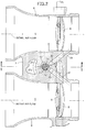
- FIG. 1 is a longitudinal cross-sectional view of a bypass air volume control system of a first embodiment in a fully closed state, the cross-sectional view taken along a line 1-1 in FIG. 2;
- FIG. 2 is a cross-sectional view taken along a line 2-2 in FIG. 1 ;
- FIG. 3 is a longitudinal cross-sectional view corresponding to FIG. 1 , showing the bypass air volume control system in a fully opened state;
- FIG. 4 is a longitudinal cross-sectional view of a second embodiment corresponding to FIG. 1 .
- FIGS. 1 to 3 A first embodiment of the present invention will be described with reference to FIGS. 1 to 3 .
- a pair of throttle bodies 6, 6 respectively having intake passages 5, 5 extending parallel to each other are disposed in parallel and connected to each other through a connecting portion 7 integrally formed with the throttle bodies 6.
- Butterfly throttle valves 8, 8 for controlling the opening degree of the intake passages 5 are fixed to a throttle valve shaft 9 which traverses the intake passages 5 and is rotatably movably supported on the throttle bodies 6.
- the connecting portion 7 integrally formed with the two throttle bodies 6 includes: a valve-body guide hole 10 extending in an up-and-down direction and having one end at the lower end position; a fitting hole 11 formed to have a larger diameter than the valve-body guide hole 10 and being continuous with the one end (lower end) of the valve-body guide hole 10; and an attachment hole 12 formed to have a larger diameter than the valve-body guide hole 10 and being continuous with the other end (upper end) of the valve-body guide hole 10.
- the valve-body guide hole 10, the fitting hole 11, and the attachment hole 12 are coaxially provided in such a manner that outer ends of the fitting hole 11 and the attachment hole 12 are opened to the outside.
- a step motor 13 is fixedly provided which is drive means for generating a driving force in an axial direction of the valve-body guide hole 10.
- the step motor 13 is covered with a cover 14 which has a cylindrical portion 14a fitted into the attachment hole 12.
- the cover 14 has flange portions 14b fastened to the connecting portion 7 with screw members 15.
- the step motor 13 is fixed to the connecting portion 7 integrally formed with the throttle bodies 6 at the side of the other end of the valve-body guide hole 10.
- an annular first seal member 16 which is resiliently in contact with an inner periphery of the attachment hole 12 is attached to an outer periphery of the cylindrical portion 14a.
- annular step portion 17 facing the step motor 13, i.e., upward is formed between the other end of the valve-body guide hole 10 and the attachment hole 12.
- a cylindrical sleeve 18 is inserted in and fixed to the cylindrical portion 14a in such a manner that the cylindrical sleeve 18 together with a tip end of the cylindrical portion 14a comes into contact with the annular step portion 17.
- the sleeve 18 is formed to have a smaller inner diameter than the valve-body guide hole 10.
- the step motor 13 has a motor shaft 19 disposed in the sleeve 18 coaxially with the axis of the valve-body guide hole 10.
- a male screw 20 provided on an outer periphery of the motor shaft 19 is screwed into a cylindrical nut 21 coaxially disposed in the valve-body guide hole 10.
- a flange portion 21a is provided on an end portion, on the step motor 13 side, of the nut 21, the flange portion 21a protruding outward in a radial direction of the nut 21 and being slidably fitted in the sleeve 18.
- An end portion of the nut 21 opposite from the step motor 13 is joined by crimping to a valve-body supporting member 25 in the shape of a short cylinder.
- a retaining ring 26 is fitted and attached to an outer periphery of the valve-body supporting member 25.
- a valve body 27 made of a synthetic resin is slidably fitted into the valve-body guide hole 10.
- the valve body 27 integrally has a large diameter portion 27a whose outer periphery slides on and contacts an inner periphery of the valve-body guide hole 10, and a small diameter portion 27b continuous with the large diameter portion 27a in such a manner as to be inserted in the sleeve 18.
- the valve body 27 is formed in such a dented cylindrical shape that the valve body 27 coaxially surrounds the nut 21 except for the flange portion 21a thereof and coaxially surrounds the valve-body supporting member 25 above the retaining ring 26.
- a coiled spring 28 is provided in a compressed state between the flange portion 21a of the nut 21 and the valve body 27, the coiled spring 28 surrounding a portion of the nut 21.
- the valve body 27 is biased by the spring 28 in such a manner that a lower end of the valve body 27 is received by the retaining ring 26.
- the connecting portion 7 is provided with an annular flat surface 29 between the one end of the valve-body guide hole 10 and the fitting hole 11 along a plane perpendicular to the axis of the valve-body guide hole 10.
- the annular flat surface 29 is an annular step portion facing a side opposite to the step motor 13, i.e., downward.
- the connecting portion 7 is provided with: a pair of air control grooves 30, 30 opened at the inner periphery of the valve-body guide hole 10 and opened at the flat surface 29; and downstream air passages 31, 31 whose one ends are continuous with these air control grooves 30 and whose other ends are continuous with the intake passages 5 of the two throttle bodies 6 downstream of the throttle valves 8, respectively.
- Opening ends of the air control grooves 30 at the flat surface 29 are closed by a blocking member 32.
- this blocking member 32 functions as a stopper for restricting closing movement of the valve body 27 side.
- the blocking member 32 is formed in such a manner that at least a portion thereof exists inside the inner periphery of the valve-body guide hole 10 on the plane including the flat surface 29.
- valve body 27 As shown in FIG. 1 , while the downward movement of the valve body 27 is restricted by being in contact with the blocking member 32, the opening ends of the air control grooves 30 at the valve-body guide hole 10 are fully closed by the valve body 27.
- the valve body 27 When the valve body 27 is elevated as shown in FIG. 3 , the opening ends of the air control grooves 30 at the valve-body guide hole 10 are in a fully opened state. Thus, the valve body 27 is lowered and elevated between the fully closed position and the fully opened position.
- the blocking member 32 is formed to have a flange portion 32b integrally at an end portion, on the valve-body guide hole 10 side, of a cylindrical portion 32a thereof, the flange portion 32b protruding inward in a radial direction of the blocking member 32.
- An inner periphery of the flange portion 32b forms a passage hole 35 having a smaller diameter than the valve-body guide hole 10.
- the passage hole 35 having a smaller diameter than the valve-body guide hole 10 is provided, for example, in a central portion of the blocking member 32.
- the cylindrical portion 32a is formed in a cylindrical shape, which makes the blocking member 32 have an annular appearance.
- the blocking member 32 is fitted in and fixed to the fitting hole 11 in such a manner that the opening ends of the air control grooves 30 at the flat surface 29 are closed by the flange portion 32b.
- One end portion of a pipe 37 bent into, for example, a substantially L shape is fitted in the cylindrical portion 32a of the blocking member 32 with an annular second seal member 38 therebetween while the other end portion of the pipe 37 is connected to a hose 36 for guiding air cleaned with an unillustrated air cleaner.
- the pipe 37 is fixed to the connecting portion 7 of the throttle bodies 6 through the blocking member 32.
- the upstream air passage 39 includes the hose 36, the pipe 37, and the passage hole 35 in the blocking member 32.
- the passage hole 35 is provided, for example, in the central portion of the blocking member 32 in such a manner as to constitute a part of the upstream air passage 39.
- valve body 27 When the valve body 27 reaches the fully closed position where the openings of the air control grooves 30 at the inner periphery of the valve-body guide hole 10 are fully closed, the closing movement of the valve body 27 is restricted by the blocking member 32 which closes the opening ends of the air control grooves 30 at the flat surface 29 having an opening at the one end of the valve-body guide hole 10.
- the blocking member 32 functioning as the stopper is formed in such a manner that at least a portion thereof exists inside the inner periphery of the valve-body guide hole 10 on the plane including the flat surface 29. Thus, this eliminates the need to process and form a valve-body guide hole continuous with the valve-body guide hole 10 in the blocking member 32.
- valve-body guide hole 10 just in the connecting portion 7 integrally formed with the throttle bodies 6. Accordingly, a metallic machining drill having a high hardness does not have to be used in processing the valve-body guide hole 10, and an increase in the processing cost can be avoided. Moreover, a burr or the like does not enter a joint surface between the throttle bodies 6 and the blocking member 32, and a post-treatment such as high-pressure cleaning is not required, either. Hence, reductions in the number of operation steps and the production cost can be achieved.
- the passage hole 35 having a smaller diameter than the valve-body guide hole 10 is provided, for example, in the central portion of the blocking member 32 in such a manner as to constitute a part of the upstream air passage 39 for guiding atmospheric air to the one end of the valve-body guide hole 10.
- the blocking member 32 can be utilized as a constituent member of the upstream air passage 39.
- valve-body guide hole 10 is provided in the connecting portion 7 in such a manner as to extend in the up-and-down direction.
- the passage hole 35 in the blocking member 32 is disposed at the uppermost portion of the upstream air passage 39 connected to the lower end of the valve-body guide hole 10. Accordingly, even if dust or the like enters the upstream air passage 39 by any chance, the gravity on the dust and the flow of fluid prevent the dust from adhering to an inner periphery of the passage hole 35 as much as possible. This makes it possible to avoid a situation where the dust or the like sandwiched between the valve body 27 and the blocking member 32 hinders the movement of the valve body 27 to the fully closed position. It can also suppress entering of the dust to the valve-body guide hole 10 as much as possible. This is desirable particularly when a flow amount is controlled finely during idle driving, for example.
- the blocking member 32 is formed to have an annular appearance, this enables press-fitting of the blocking member 32 to the connecting portion 7 integrally with the throttle bodies 6, and further cost reduction is possible.
- the pipe 37 for guiding atmospheric air is fixed to the connecting portion 7 integrally formed with the throttle bodies 6 through the blocking member 32.
- this increases the degree of freedom of the piping operation for introducing atmospheric air to the one end of the valve-body guide hole 10.
- a second embodiment of the present invention will be described with reference to FIG. 4 .
- the parts corresponding to those in the first embodiment are denoted by the same reference numerals and merely illustrated. Detailed description thereof will be omitted.
- the opening ends of the air control grooves 30 at the annular flat surface 29 provided between the one end of the valve-body guide hole 10 and the fitting hole 11 is closed by a blocking member 41.
- this blocking member 41 functions as a stopper for restricting closing movement of the valve body 27.
- the blocking member 41 is formed in such a manner that at least a portion thereof exists inside the inner periphery of the valve-body guide hole 10 on the plane including the flat surface 29.
- the blocking member 41 is formed to have an annular appearance in a pipe-like shape bent into a substantially L shape in such a manner that, for example, one end thereof is connected to the hose 36.
- the blocking member 41 is fitted in and fixed to the fitting hole 11 in such a manner that the opening ends of the air control grooves 30 at the flat surface 29 are closed by the one end of the blocking member 41.
- An annular third seal member 43 which is resiliently in contact with an inner periphery of the fitting hole 11 is attached to an outer periphery of the blocking member 41.
- a passage hole 42 having a smaller diameter than the valve-body guide hole 10 is provided, for example, in a central portion of the blocking member 41.
- This passage hole 42 constitutes a part of an upstream air passage 44 for guiding atmospheric air to the one end of the valve-body guide hole 10.
- the operations as those in the first embodiment can be produced. Additionally, since the blocking member 41 is formed into the pipe-like shape to guide atmospheric air to the one end of the valve-body guide hole 10, the number of components is reduced and further cost reduction is possible. Moreover, using the third seal member 43 attached to the outer periphery of the blocking member 41 having an annular appearance, a portion between the outer periphery of the blocking member 41 and the connecting portion 7 integrally formed with the throttle bodies 6 is easily sealed.
- atmospheric air is introduced to the one end of the valve-body guide hole 10.
- a control groove continuous with the upstream air passage for introducing atmospheric air may be provided in the inner periphery on the one end side of the valve-body guide hole 10.
- a bypass air volume control system for a throttle body includes a throttle body provided with: a valve-body guide hole into which a valve body is slidably fitted and into which atmospheric air is introduced; a flat surface formed by opening one end of the valve-body guide hole; and an air control groove which is opened at an inner periphery of the valve-body guide hole in such a manner as to be opened and closed by the valve body and which is opened at the flat surface, a blocking member being fixed to the throttle body and closing an opening end of the air control groove at the flat surface.
- the blocking member (32) is formed in such a manner that at least a portion thereof exists inside an inner periphery of the valve-body guide hole (10) on the plane including the flat surface (29), the blocking member (32) functioning as a stopper for restricting closing movement of the valve body (27) when the valve body (27) reaches a fully closed position where the opening of the air control groove (30) at the inner periphery of the valve-body guide hole (10) is fully closed. Accordingly, it is possible to achieve reduction in production cost by reducing the processing cost and reducing the number of operation steps.
Description
- The present invention relates to a bypass air volume control system for a throttle body, including: a throttle body which has an intake passage with a throttle valve disposed therein, to which drive means is fixed, and which is provided with a valve-body guide hole into which a valve body connected to the drive means is slidably fitted, and into which atmospheric air is introduced, a flat surface formed by opening one end of the valve-body guide hole to face a side opposite to the drive means and disposed along a plane perpendicular to an axis of the valve-body guide hole, an air control groove which is opened at an inner periphery of the valve-body guide hole in such a manner as to be opened and closed by the valve body and which is opened at the flat surface, and a downstream air passage having one end continuous with the air control groove and the other end continuous with the intake passage downstream of the throttle valve; and a blocking member which is fixed to the throttle body and which closes an opening end of the air control groove at the flat surface.
- A bypass air volume control system for a throttle body having the following configuration is known from Japanese Patent Application Laid-open No.
2007-132235 EP 1 296 049 A1 - However, in Japanese Patent Application Laid-open No.
2007-132235 - The present invention has been made in view of such circumstances. An object of the present invention is to provide a bypass air volume control system for a throttle body, which achieves reduction in production cost by reducing the processing cost and reducing the number of operation steps.
- In order to achieve the object, according to the invention described in
claim 1, there is provided a bypass air volume control system for a throttle body, including: a throttle body which has an intake passage with a throttle valve disposed therein, to which drive means is fixed, and which is provided with a valve-body guide hole into which a valve body connected to the drive means is slidably fitted, and into which atmospheric air is introduced, a flat surface formed by opening one end of the valve-body guide hole to face a side opposite to the drive means and disposed along a plane perpendicular to an axis of the valve-body guide hole, an air control groove which is opened at an inner periphery of the valve-body guide hole in such a manner as to be opened and closed by the valve body and which is opened at the flat surface, and a downstream air passage having one end continuous with the air control groove and the other end continuous with the intake passage downstream of the throttle valve; and a blocking member which is fixed to the throttle body and which closes an opening end of the air control groove at the flat surface, wherein the blocking member is formed in such a manner that at least a portion thereof exists inside the inner periphery of the valve-body guide hole on the plane including the flat surface, the blocking member functioning as a stopper for restricting closing movement of the valve body when the valve body reaches a fully closed position where the opening of the air control groove at the inner periphery of the valve-body guide hole is fully closed. - With the above configuration, the blocking member has a function as the stopper for restricting the closing movement of the valve body when the valve body reaches the fully closed position. The blocking member is formed in such a manner that at least a portion thereof exists inside the inner periphery of the valve-body guide hole for the throttle body on the plane including the flat surface. Thus, this eliminates the need to process and form a valve-body guide hole continuous with the valve-body guide hole in the blocking member. It is only necessary to form the valve-body guide hole just in the throttle body. Accordingly, a metallic machining drill having a high hardness does not have to be used in processing the valve-body guide hole, and an increase in the processing cost can be avoided. Moreover, a burr or the like does not enter a joint surface between the throttle body and the blocking member, and a post-treatment such as high-pressure cleaning is not required, either. Hence, reductions in the number of operation steps and the production cost can be achieved.
- According to the invention described in
claim 2, in addition to the configuration ofclaim 1, a passage hole having a smaller diameter than the valve-body guide hole is provided in the blocking member in such a manner as to constitute a part of an upstream air passage for introducing atmospheric air to the one end of the valve-body guide hole. - With the above configuration, the passage hole having a smaller diameter than the valve-body guide hole for the throttle body is provided in the blocking member, the passage hole constituting a part of the upstream air passage for guiding atmospheric air to the one end of the valve-body guide hole. Accordingly, the blocking member can be utilized as a constituent member of the upstream air passage.
- According to the invention described in claim 3, in addition to the configuration of
claim - With the above configuration, the blocking member has an annular appearance. This enables press-fitting of the blocking member to the throttle body. Thus, further cost reduction is possible and a portion between the outer periphery of the blocking member and the throttle body is easily sealed.
- According to the invention described in claim 4, in addition to the configuration of any one of
claims 1 to 3, a pipe for guiding atmospheric air is fixed to the throttle body through the blocking member. - With the above configuration, the pipe for guiding atmospheric air is fixed to the throttle body through the blocking member. Thus, this increases the degree of freedom of the piping operation for introducing atmospheric air to the one end of valve-body guide hole.
- According to the invention described in
claim 5, in addition to the configuration of any one ofclaims 1 to 3, the blocking member is formed into a pipe-like shape to guide atmospheric air to the one end of the valve-body guide hole. - With the above configuration, the blocking member is formed into a pipe-like shape for guiding atmospheric air. Accordingly, the number of components is reduced and further cost reduction is possible.
- Here, a
step motor 13 of embodiments corresponds to the drive means of the present invention. - The above and other objects, characteristics and advantages of the present invention will be clear from detailed descriptions of the preferred embodiments which will be provided below while referring to the attached drawings.
-
FIG. 1 is a longitudinal cross-sectional view of a bypass air volume control system of a first embodiment in a fully closed state, the cross-sectional view taken along a line 1-1 inFIG. 2; FIG. 2 is a cross-sectional view taken along a line 2-2 inFIG. 1 ;FIG. 3 is a longitudinal cross-sectional view corresponding toFIG. 1 , showing the bypass air volume control system in a fully opened state; andFIG. 4 is a longitudinal cross-sectional view of a second embodiment corresponding toFIG. 1 . - Hereinafter, embodiments of the present invention will be described with reference to the accompanying drawings.
- A first embodiment of the present invention will be described with reference to
FIGS. 1 to 3 . First, referring toFIGS. 1 and2 , a pair ofthrottle bodies intake passages portion 7 integrally formed with thethrottle bodies 6.Butterfly throttle valves intake passages 5 are fixed to athrottle valve shaft 9 which traverses theintake passages 5 and is rotatably movably supported on thethrottle bodies 6. - The connecting
portion 7 integrally formed with the twothrottle bodies 6 includes: a valve-body guide hole 10 extending in an up-and-down direction and having one end at the lower end position; afitting hole 11 formed to have a larger diameter than the valve-body guide hole 10 and being continuous with the one end (lower end) of the valve-body guide hole 10; and anattachment hole 12 formed to have a larger diameter than the valve-body guide hole 10 and being continuous with the other end (upper end) of the valve-body guide hole 10. The valve-body guide hole 10, thefitting hole 11, and theattachment hole 12 are coaxially provided in such a manner that outer ends of thefitting hole 11 and theattachment hole 12 are opened to the outside. - On an upper portion of the connecting
portion 7, astep motor 13 is fixedly provided which is drive means for generating a driving force in an axial direction of the valve-body guide hole 10. Thestep motor 13 is covered with acover 14 which has acylindrical portion 14a fitted into theattachment hole 12. Thecover 14 hasflange portions 14b fastened to the connectingportion 7 withscrew members 15. Thereby, thestep motor 13 is fixed to the connectingportion 7 integrally formed with thethrottle bodies 6 at the side of the other end of the valve-body guide hole 10. Moreover, an annularfirst seal member 16 which is resiliently in contact with an inner periphery of theattachment hole 12 is attached to an outer periphery of thecylindrical portion 14a. - Meanwhile, an
annular step portion 17 facing thestep motor 13, i.e., upward is formed between the other end of the valve-body guide hole 10 and theattachment hole 12. Acylindrical sleeve 18 is inserted in and fixed to thecylindrical portion 14a in such a manner that thecylindrical sleeve 18 together with a tip end of thecylindrical portion 14a comes into contact with theannular step portion 17. Thesleeve 18 is formed to have a smaller inner diameter than the valve-body guide hole 10. - The
step motor 13 has amotor shaft 19 disposed in thesleeve 18 coaxially with the axis of the valve-body guide hole 10. Amale screw 20 provided on an outer periphery of themotor shaft 19 is screwed into acylindrical nut 21 coaxially disposed in the valve-body guide hole 10. Moreover, aflange portion 21a is provided on an end portion, on thestep motor 13 side, of thenut 21, theflange portion 21a protruding outward in a radial direction of thenut 21 and being slidably fitted in thesleeve 18. A protrudingportion 22 protruding from the outer periphery of theflange portion 21a engages with alocking groove 23 which is provided on an inner periphery of thesleeve 18 and which extends in an axial direction of thesleeve 18. This inhibits rotation of thenut 21, but thenut 21 can move in the axial direction as themotor shaft 19 rotates in accordance with an operation of thestep motor 13. - An end portion of the
nut 21 opposite from thestep motor 13 is joined by crimping to a valve-body supporting member 25 in the shape of a short cylinder. Aretaining ring 26 is fitted and attached to an outer periphery of the valve-body supporting member 25. - A
valve body 27 made of a synthetic resin is slidably fitted into the valve-body guide hole 10. Thevalve body 27 integrally has alarge diameter portion 27a whose outer periphery slides on and contacts an inner periphery of the valve-body guide hole 10, and asmall diameter portion 27b continuous with thelarge diameter portion 27a in such a manner as to be inserted in thesleeve 18. Thevalve body 27 is formed in such a dented cylindrical shape that thevalve body 27 coaxially surrounds thenut 21 except for theflange portion 21a thereof and coaxially surrounds the valve-body supporting member 25 above the retainingring 26. - Further, a
coiled spring 28 is provided in a compressed state between theflange portion 21a of thenut 21 and thevalve body 27, thecoiled spring 28 surrounding a portion of thenut 21. Thevalve body 27 is biased by thespring 28 in such a manner that a lower end of thevalve body 27 is received by the retainingring 26. Thereby, when thestep motor 13 rotates to a side where thenut 21 and the valve-body supporting member 25 are lowered, thevalve body 27 is lowered accompanying thenut 21 and the valve-body supporting member 25 by a spring biased force of thespring 28. When thestep motor 13 rotates to a side where thenut 21 and the valve-body supporting member 25 are elevated, thevalve body 27 is pushed up by the retainingring 26 and elevated. - The connecting
portion 7 is provided with an annularflat surface 29 between the one end of the valve-body guide hole 10 and thefitting hole 11 along a plane perpendicular to the axis of the valve-body guide hole 10. The annularflat surface 29 is an annular step portion facing a side opposite to thestep motor 13, i.e., downward. In addition, the connectingportion 7 is provided with: a pair ofair control grooves body guide hole 10 and opened at theflat surface 29; anddownstream air passages air control grooves 30 and whose other ends are continuous with theintake passages 5 of the twothrottle bodies 6 downstream of thethrottle valves 8, respectively. - Opening ends of the
air control grooves 30 at theflat surface 29 are closed by a blockingmember 32. When thevalve body 27 reaches a fully closed position where the openings of theair control grooves 30 at the inner periphery of the valve-body guide hole 10 are fully closed, this blockingmember 32 functions as a stopper for restricting closing movement of thevalve body 27 side. The blockingmember 32 is formed in such a manner that at least a portion thereof exists inside the inner periphery of the valve-body guide hole 10 on the plane including theflat surface 29. - As shown in
FIG. 1 , while the downward movement of thevalve body 27 is restricted by being in contact with the blockingmember 32, the opening ends of theair control grooves 30 at the valve-body guide hole 10 are fully closed by thevalve body 27. When thevalve body 27 is elevated as shown inFIG. 3 , the opening ends of theair control grooves 30 at the valve-body guide hole 10 are in a fully opened state. Thus, thevalve body 27 is lowered and elevated between the fully closed position and the fully opened position. - The blocking
member 32 is formed to have aflange portion 32b integrally at an end portion, on the valve-body guide hole 10 side, of acylindrical portion 32a thereof, theflange portion 32b protruding inward in a radial direction of the blockingmember 32. An inner periphery of theflange portion 32b forms apassage hole 35 having a smaller diameter than the valve-body guide hole 10. In other words, thepassage hole 35 having a smaller diameter than the valve-body guide hole 10 is provided, for example, in a central portion of the blockingmember 32. - Furthermore, the
cylindrical portion 32a is formed in a cylindrical shape, which makes the blockingmember 32 have an annular appearance. By, for example, press-fitting, the blockingmember 32 is fitted in and fixed to thefitting hole 11 in such a manner that the opening ends of theair control grooves 30 at theflat surface 29 are closed by theflange portion 32b. - One end portion of a
pipe 37 bent into, for example, a substantially L shape is fitted in thecylindrical portion 32a of the blockingmember 32 with an annularsecond seal member 38 therebetween while the other end portion of thepipe 37 is connected to ahose 36 for guiding air cleaned with an unillustrated air cleaner. Thepipe 37 is fixed to the connectingportion 7 of thethrottle bodies 6 through the blockingmember 32. - Thus, atmospheric air cleaned by the air cleaner is introduced to the one end of the valve-
body guide hole 10 through anupstream air passage 39. Theupstream air passage 39 includes thehose 36, thepipe 37, and thepassage hole 35 in the blockingmember 32. Thepassage hole 35 is provided, for example, in the central portion of the blockingmember 32 in such a manner as to constitute a part of theupstream air passage 39. - Next, operations of this first embodiment will be described. When the
valve body 27 reaches the fully closed position where the openings of theair control grooves 30 at the inner periphery of the valve-body guide hole 10 are fully closed, the closing movement of thevalve body 27 is restricted by the blockingmember 32 which closes the opening ends of theair control grooves 30 at theflat surface 29 having an opening at the one end of the valve-body guide hole 10. The blockingmember 32 functioning as the stopper is formed in such a manner that at least a portion thereof exists inside the inner periphery of the valve-body guide hole 10 on the plane including theflat surface 29. Thus, this eliminates the need to process and form a valve-body guide hole continuous with the valve-body guide hole 10 in the blockingmember 32. It is only necessary to form the valve-body guide hole 10 just in the connectingportion 7 integrally formed with thethrottle bodies 6. Accordingly, a metallic machining drill having a high hardness does not have to be used in processing the valve-body guide hole 10, and an increase in the processing cost can be avoided. Moreover, a burr or the like does not enter a joint surface between thethrottle bodies 6 and the blockingmember 32, and a post-treatment such as high-pressure cleaning is not required, either. Hence, reductions in the number of operation steps and the production cost can be achieved. - Further, the
passage hole 35 having a smaller diameter than the valve-body guide hole 10 is provided, for example, in the central portion of the blockingmember 32 in such a manner as to constitute a part of theupstream air passage 39 for guiding atmospheric air to the one end of the valve-body guide hole 10. Thus, the blockingmember 32 can be utilized as a constituent member of theupstream air passage 39. - Furthermore, in this embodiment, the valve-
body guide hole 10 is provided in the connectingportion 7 in such a manner as to extend in the up-and-down direction. In addition, thepassage hole 35 in the blockingmember 32 is disposed at the uppermost portion of theupstream air passage 39 connected to the lower end of the valve-body guide hole 10. Accordingly, even if dust or the like enters theupstream air passage 39 by any chance, the gravity on the dust and the flow of fluid prevent the dust from adhering to an inner periphery of thepassage hole 35 as much as possible. This makes it possible to avoid a situation where the dust or the like sandwiched between thevalve body 27 and the blockingmember 32 hinders the movement of thevalve body 27 to the fully closed position. It can also suppress entering of the dust to the valve-body guide hole 10 as much as possible. This is desirable particularly when a flow amount is controlled finely during idle driving, for example. - In addition, since the blocking
member 32 is formed to have an annular appearance, this enables press-fitting of the blockingmember 32 to the connectingportion 7 integrally with thethrottle bodies 6, and further cost reduction is possible. - Moreover, the
pipe 37 for guiding atmospheric air is fixed to the connectingportion 7 integrally formed with thethrottle bodies 6 through the blockingmember 32. Thus, this increases the degree of freedom of the piping operation for introducing atmospheric air to the one end of the valve-body guide hole 10. - A second embodiment of the present invention will be described with reference to
FIG. 4 . The parts corresponding to those in the first embodiment are denoted by the same reference numerals and merely illustrated. Detailed description thereof will be omitted. - The opening ends of the
air control grooves 30 at the annularflat surface 29 provided between the one end of the valve-body guide hole 10 and thefitting hole 11 is closed by a blockingmember 41. When thevalve body 27 reaches to the fully closed position where the openings of theair control grooves 30 at the inner periphery of the valve-body guide hole 10 are fully closed, this blockingmember 41 functions as a stopper for restricting closing movement of thevalve body 27. The blockingmember 41 is formed in such a manner that at least a portion thereof exists inside the inner periphery of the valve-body guide hole 10 on the plane including theflat surface 29. - The blocking
member 41 is formed to have an annular appearance in a pipe-like shape bent into a substantially L shape in such a manner that, for example, one end thereof is connected to thehose 36. The blockingmember 41 is fitted in and fixed to thefitting hole 11 in such a manner that the opening ends of theair control grooves 30 at theflat surface 29 are closed by the one end of the blockingmember 41. An annularthird seal member 43 which is resiliently in contact with an inner periphery of thefitting hole 11 is attached to an outer periphery of the blockingmember 41. - Furthermore, a
passage hole 42 having a smaller diameter than the valve-body guide hole 10 is provided, for example, in a central portion of the blockingmember 41. Thispassage hole 42 constitutes a part of anupstream air passage 44 for guiding atmospheric air to the one end of the valve-body guide hole 10. - According to this second embodiment, the operations as those in the first embodiment can be produced. Additionally, since the blocking
member 41 is formed into the pipe-like shape to guide atmospheric air to the one end of the valve-body guide hole 10, the number of components is reduced and further cost reduction is possible. Moreover, using thethird seal member 43 attached to the outer periphery of the blockingmember 41 having an annular appearance, a portion between the outer periphery of the blockingmember 41 and the connectingportion 7 integrally formed with thethrottle bodies 6 is easily sealed. - Hereinabove, embodiments of the present invention have been described. However, the present invention is not limited to the above embodiments, and the design can be modified variously without departing from inventions described in claims.
- For example, although the above embodiments have been described by taking the case where the pair of
throttle bodies 6 are integrally connected to each other, the present invention is applicable to a single throttle body. - Moreover, in the above embodiments, atmospheric air is introduced to the one end of the valve-
body guide hole 10. Nevertheless, as similar to theair control grooves 30 continuous with thedownstream air passages 31, a control groove continuous with the upstream air passage for introducing atmospheric air may be provided in the inner periphery on the one end side of the valve-body guide hole 10. - A bypass air volume control system for a throttle body includes a throttle body provided with: a valve-body guide hole into which a valve body is slidably fitted and into which atmospheric air is introduced; a flat surface formed by opening one end of the valve-body guide hole; and an air control groove which is opened at an inner periphery of the valve-body guide hole in such a manner as to be opened and closed by the valve body and which is opened at the flat surface, a blocking member being fixed to the throttle body and closing an opening end of the air control groove at the flat surface. The blocking member (32) is formed in such a manner that at least a portion thereof exists inside an inner periphery of the valve-body guide hole (10) on the plane including the flat surface (29), the blocking member (32) functioning as a stopper for restricting closing movement of the valve body (27) when the valve body (27) reaches a fully closed position where the opening of the air control groove (30) at the inner periphery of the valve-body guide hole (10) is fully closed. Accordingly, it is possible to achieve reduction in production cost by reducing the processing cost and reducing the number of operation steps.
Claims (5)
- A bypass air volume control system for a throttle body, including:a throttle body (6) which has an intake passage (5) with a throttle valve (8) disposed therein, to which drive means (13) is fixed, and which is provided with
a valve-body guide hole (10) into which a valve body (27) connected to the drive means (13) is slidably fitted, and into which atmospheric air is introduced,
a flat surface (29) formed by opening one end of the valve-body guide hole (10) to face a side opposite to the drive means (13) and disposed along a plane perpendicular to an axis of the valve-body guide hole (10),
an air control groove (30) which is directly opened at an inner periphery of the valve-body guide hole (10) in such a manner as to be opened and closed by the valve body (27) and which is directly opened at the flat surface (29) such that the air control groove (30) is continuous with the flat surface (29), and.
a downstream air passage (31) having one end continuous with the air control groove (30) and the other end continuous with the intake passage (5) downstream of the throttle valve (8); and
a blocking member (32, 41) which has an annular appearance and is fixed to the throttle body (6) by press-fitting so as to close an opening end of the air control groove (30) at the flat surface (29),
wherein the air control groove (30) and the valve-body guide hole (10) are formed directly in the throttle body (6); and
wherein the blocking member (32, 41), is formed in such a manner that at least a portion thereof exists inside the inner periphery of the valve-body guide hole (10) on the plane including the flat surface (29), the blocking member (32, 41) functioning as a stopper for restricting closing movement of the valve body (27) when the valve body (27) reaches a fully closed position where the opening of the air control groove (30) at the inner periphery of the valve-body guide hole (10) is fully closed. - The bypass air volume control system for a throttle body according to claim 1,
wherein a passage hole (35, 42) having a smaller diameter than the valve-body guide hole (10) is provided in the blocking member (32, 41) in such a manner as to constitute a part of an upstream air passage (39, 44) for introducing atmospheric air to the one end of the valve-body guide hole (10). - The bypass air volume control system for a throttle body according to claim 1 or 2,
wherein as said throttle body, a plurality of throttle bodies (6) are provided as a single member, and as said air control groove, a plurality of air control grooves (30) are provided so as to communicate with the respective intake passages (5) of the throttle bodies (6). - The bypass air volume control system for a throttle body according to any one of claims 1 to 3,
wherein a pipe (37) for guiding atmospheric air is formed separately from the throttle body (6) and fixed to the throttle body (6) through the blocking member (32), and the pipe (37) is of a substantially L-shape and fitted into the blocking member (32) via an annular seal member (38) which is mounted on a cylindrical surface of the pipe (37). - The bypass air volume control system for a throttle body according to any one of claims 1 to 3,
wherein the blocking member (41) is formed separately from the throttle body (6) and formed into a pipe-like shape to guide atmospheric air to the one end of the valve-body guide hole (10).
Applications Claiming Priority (1)
| Application Number | Priority Date | Filing Date | Title |
|---|---|---|---|
| JP2010245343A JP5675276B2 (en) | 2010-11-01 | 2010-11-01 | Bypass air volume control device for throttle body |
Publications (2)
| Publication Number | Publication Date |
|---|---|
| EP2447512A1 EP2447512A1 (en) | 2012-05-02 |
| EP2447512B1 true EP2447512B1 (en) | 2017-08-23 |
Family
ID=44862759
Family Applications (1)
| Application Number | Title | Priority Date | Filing Date |
|---|---|---|---|
| EP11187101.8A Not-in-force EP2447512B1 (en) | 2010-11-01 | 2011-10-28 | Bypass air volume control system for throttle body |
Country Status (2)
| Country | Link |
|---|---|
| EP (1) | EP2447512B1 (en) |
| JP (1) | JP5675276B2 (en) |
Families Citing this family (3)
| Publication number | Priority date | Publication date | Assignee | Title |
|---|---|---|---|---|
| JP6297338B2 (en) | 2014-01-27 | 2018-03-20 | 株式会社ミクニ | Flow control valve |
| JP6193788B2 (en) * | 2014-03-14 | 2017-09-06 | 株式会社ケーヒン | Bypass valve device |
| JP6461266B1 (en) * | 2017-09-08 | 2019-01-30 | 株式会社ケーヒン | Intake control device |
Family Cites Families (8)
| Publication number | Priority date | Publication date | Assignee | Title |
|---|---|---|---|---|
| DE3028898A1 (en) * | 1980-07-30 | 1982-03-04 | Robert Bosch Gmbh, 7000 Stuttgart | DEVICE FOR CONTROLLING THE IDLE SPEED OF AN INTERNAL COMBUSTION ENGINE |
| JPH0752375Y2 (en) * | 1987-01-16 | 1995-11-29 | 日本電装株式会社 | Auxiliary air control device for internal combustion engine |
| JPH0219869U (en) * | 1988-07-25 | 1990-02-09 | ||
| JPH09144569A (en) * | 1995-11-28 | 1997-06-03 | Jidosha Kiki Co Ltd | Exhaust brake device |
| DE60136179D1 (en) * | 2000-06-19 | 2008-11-27 | Keihin Corp | CONTROL OF THE BYPASS AIR QUANTITY |
| JP4459154B2 (en) * | 2005-11-09 | 2010-04-28 | 株式会社ケーヒン | Air bypass device for multiple throttle bodies |
| JP2007132235A (en) * | 2005-11-09 | 2007-05-31 | Keihin Corp | Air bypass device for multiple throttle body |
| JP2007332904A (en) * | 2006-06-16 | 2007-12-27 | Mikuni Corp | Valve device and idle air quantity control device |
-
2010
- 2010-11-01 JP JP2010245343A patent/JP5675276B2/en not_active Expired - Fee Related
-
2011
- 2011-10-28 EP EP11187101.8A patent/EP2447512B1/en not_active Not-in-force
Non-Patent Citations (1)
| Title |
|---|
| None * |
Also Published As
| Publication number | Publication date |
|---|---|
| JP5675276B2 (en) | 2015-02-25 |
| EP2447512A1 (en) | 2012-05-02 |
| JP2012097650A (en) | 2012-05-24 |
Similar Documents
| Publication | Publication Date | Title |
|---|---|---|
| US10041401B2 (en) | Overrun air recirculation valve for a compressor of an internal combustion engine | |
| US10041396B2 (en) | Overrun air recirculation valve for a compressor of an internal combustion engine | |
| EP1777447B1 (en) | Valve for adjusting the flow-rate of fluids, particularly refrigeration fluids | |
| CN100591911C (en) | Valve for use in a fuel line of a motor vehicle | |
| US9929417B2 (en) | Valve device | |
| WO2014089953A1 (en) | Electronic expansion valve | |
| JPWO2008090657A1 (en) | Flow control device | |
| EP2447512B1 (en) | Bypass air volume control system for throttle body | |
| US9915208B2 (en) | Flap device for an internal combustion engine | |
| US10036480B2 (en) | Clamped bonnet assembly for an axial flow valve and axial flow valve comprising same | |
| JP2013224708A (en) | Motor-operated valve | |
| JP4418267B2 (en) | Check valve | |
| US20080116408A1 (en) | Valve for closing a seawater pipe | |
| US11313485B2 (en) | Electric valve and manufacturing method thereof | |
| US20180347706A1 (en) | Shaft Sealing Device | |
| WO2016031109A1 (en) | Fuel tank check valve | |
| KR970008665B1 (en) | Pressure regulator device and fuel line receptor | |
| WO2021085077A1 (en) | Egr valve system | |
| CN114198538A (en) | Control valve | |
| US20210140549A1 (en) | Valve | |
| CN111594628A (en) | Electronic expansion valve | |
| US10280845B2 (en) | Valve device in a motor vehicle | |
| US20050211519A1 (en) | Brake servo-unit comprising a floating element bearing offset valve seats | |
| CN113227558B (en) | Air inlet device | |
| EP3557115B1 (en) | Valve device |
Legal Events
| Date | Code | Title | Description |
|---|---|---|---|
| PUAI | Public reference made under article 153(3) epc to a published international application that has entered the european phase |
Free format text: ORIGINAL CODE: 0009012 |
|
| 17P | Request for examination filed |
Effective date: 20111028 |
|
| AK | Designated contracting states |
Kind code of ref document: A1 Designated state(s): AL AT BE BG CH CY CZ DE DK EE ES FI FR GB GR HR HU IE IS IT LI LT LU LV MC MK MT NL NO PL PT RO RS SE SI SK SM TR |
|
| AX | Request for extension of the european patent |
Extension state: BA ME |
|
| GRAP | Despatch of communication of intention to grant a patent |
Free format text: ORIGINAL CODE: EPIDOSNIGR1 |
|
| INTG | Intention to grant announced |
Effective date: 20170321 |
|
| GRAS | Grant fee paid |
Free format text: ORIGINAL CODE: EPIDOSNIGR3 |
|
| GRAA | (expected) grant |
Free format text: ORIGINAL CODE: 0009210 |
|
| AK | Designated contracting states |
Kind code of ref document: B1 Designated state(s): AL AT BE BG CH CY CZ DE DK EE ES FI FR GB GR HR HU IE IS IT LI LT LU LV MC MK MT NL NO PL PT RO RS SE SI SK SM TR |
|
| REG | Reference to a national code |
Ref country code: GB Ref legal event code: FG4D |
|
| REG | Reference to a national code |
Ref country code: CH Ref legal event code: EP |
|
| REG | Reference to a national code |
Ref country code: AT Ref legal event code: REF Ref document number: 921610 Country of ref document: AT Kind code of ref document: T Effective date: 20170915 |
|
| REG | Reference to a national code |
Ref country code: IE Ref legal event code: FG4D |
|
| REG | Reference to a national code |
Ref country code: DE Ref legal event code: R096 Ref document number: 602011040796 Country of ref document: DE |
|
| REG | Reference to a national code |
Ref country code: FR Ref legal event code: PLFP Year of fee payment: 7 |
|
| REG | Reference to a national code |
Ref country code: NL Ref legal event code: MP Effective date: 20170823 |
|
| REG | Reference to a national code |
Ref country code: LT Ref legal event code: MG4D |
|
| REG | Reference to a national code |
Ref country code: AT Ref legal event code: MK05 Ref document number: 921610 Country of ref document: AT Kind code of ref document: T Effective date: 20170823 |
|
| PG25 | Lapsed in a contracting state [announced via postgrant information from national office to epo] |
Ref country code: NO Free format text: LAPSE BECAUSE OF FAILURE TO SUBMIT A TRANSLATION OF THE DESCRIPTION OR TO PAY THE FEE WITHIN THE PRESCRIBED TIME-LIMIT Effective date: 20171123 Ref country code: FI Free format text: LAPSE BECAUSE OF FAILURE TO SUBMIT A TRANSLATION OF THE DESCRIPTION OR TO PAY THE FEE WITHIN THE PRESCRIBED TIME-LIMIT Effective date: 20170823 Ref country code: SE Free format text: LAPSE BECAUSE OF FAILURE TO SUBMIT A TRANSLATION OF THE DESCRIPTION OR TO PAY THE FEE WITHIN THE PRESCRIBED TIME-LIMIT Effective date: 20170823 Ref country code: HR Free format text: LAPSE BECAUSE OF FAILURE TO SUBMIT A TRANSLATION OF THE DESCRIPTION OR TO PAY THE FEE WITHIN THE PRESCRIBED TIME-LIMIT Effective date: 20170823 Ref country code: NL Free format text: LAPSE BECAUSE OF FAILURE TO SUBMIT A TRANSLATION OF THE DESCRIPTION OR TO PAY THE FEE WITHIN THE PRESCRIBED TIME-LIMIT Effective date: 20170823 Ref country code: AT Free format text: LAPSE BECAUSE OF FAILURE TO SUBMIT A TRANSLATION OF THE DESCRIPTION OR TO PAY THE FEE WITHIN THE PRESCRIBED TIME-LIMIT Effective date: 20170823 Ref country code: LT Free format text: LAPSE BECAUSE OF FAILURE TO SUBMIT A TRANSLATION OF THE DESCRIPTION OR TO PAY THE FEE WITHIN THE PRESCRIBED TIME-LIMIT Effective date: 20170823 |
|
| PGFP | Annual fee paid to national office [announced via postgrant information from national office to epo] |
Ref country code: DE Payment date: 20171013 Year of fee payment: 7 Ref country code: FR Payment date: 20171024 Year of fee payment: 7 |
|
| PG25 | Lapsed in a contracting state [announced via postgrant information from national office to epo] |
Ref country code: GR Free format text: LAPSE BECAUSE OF FAILURE TO SUBMIT A TRANSLATION OF THE DESCRIPTION OR TO PAY THE FEE WITHIN THE PRESCRIBED TIME-LIMIT Effective date: 20171124 Ref country code: RS Free format text: LAPSE BECAUSE OF FAILURE TO SUBMIT A TRANSLATION OF THE DESCRIPTION OR TO PAY THE FEE WITHIN THE PRESCRIBED TIME-LIMIT Effective date: 20170823 Ref country code: LV Free format text: LAPSE BECAUSE OF FAILURE TO SUBMIT A TRANSLATION OF THE DESCRIPTION OR TO PAY THE FEE WITHIN THE PRESCRIBED TIME-LIMIT Effective date: 20170823 Ref country code: BG Free format text: LAPSE BECAUSE OF FAILURE TO SUBMIT A TRANSLATION OF THE DESCRIPTION OR TO PAY THE FEE WITHIN THE PRESCRIBED TIME-LIMIT Effective date: 20171123 Ref country code: ES Free format text: LAPSE BECAUSE OF FAILURE TO SUBMIT A TRANSLATION OF THE DESCRIPTION OR TO PAY THE FEE WITHIN THE PRESCRIBED TIME-LIMIT Effective date: 20170823 Ref country code: PL Free format text: LAPSE BECAUSE OF FAILURE TO SUBMIT A TRANSLATION OF THE DESCRIPTION OR TO PAY THE FEE WITHIN THE PRESCRIBED TIME-LIMIT Effective date: 20170823 Ref country code: IS Free format text: LAPSE BECAUSE OF FAILURE TO SUBMIT A TRANSLATION OF THE DESCRIPTION OR TO PAY THE FEE WITHIN THE PRESCRIBED TIME-LIMIT Effective date: 20171223 |
|
| PGFP | Annual fee paid to national office [announced via postgrant information from national office to epo] |
Ref country code: GB Payment date: 20171019 Year of fee payment: 7 Ref country code: IT Payment date: 20171025 Year of fee payment: 7 |
|
| PG25 | Lapsed in a contracting state [announced via postgrant information from national office to epo] |
Ref country code: CZ Free format text: LAPSE BECAUSE OF FAILURE TO SUBMIT A TRANSLATION OF THE DESCRIPTION OR TO PAY THE FEE WITHIN THE PRESCRIBED TIME-LIMIT Effective date: 20170823 Ref country code: RO Free format text: LAPSE BECAUSE OF FAILURE TO SUBMIT A TRANSLATION OF THE DESCRIPTION OR TO PAY THE FEE WITHIN THE PRESCRIBED TIME-LIMIT Effective date: 20170823 Ref country code: DK Free format text: LAPSE BECAUSE OF FAILURE TO SUBMIT A TRANSLATION OF THE DESCRIPTION OR TO PAY THE FEE WITHIN THE PRESCRIBED TIME-LIMIT Effective date: 20170823 |
|
| REG | Reference to a national code |
Ref country code: DE Ref legal event code: R097 Ref document number: 602011040796 Country of ref document: DE |
|
| PG25 | Lapsed in a contracting state [announced via postgrant information from national office to epo] |
Ref country code: SM Free format text: LAPSE BECAUSE OF FAILURE TO SUBMIT A TRANSLATION OF THE DESCRIPTION OR TO PAY THE FEE WITHIN THE PRESCRIBED TIME-LIMIT Effective date: 20170823 Ref country code: EE Free format text: LAPSE BECAUSE OF FAILURE TO SUBMIT A TRANSLATION OF THE DESCRIPTION OR TO PAY THE FEE WITHIN THE PRESCRIBED TIME-LIMIT Effective date: 20170823 Ref country code: MC Free format text: LAPSE BECAUSE OF FAILURE TO SUBMIT A TRANSLATION OF THE DESCRIPTION OR TO PAY THE FEE WITHIN THE PRESCRIBED TIME-LIMIT Effective date: 20170823 Ref country code: SK Free format text: LAPSE BECAUSE OF FAILURE TO SUBMIT A TRANSLATION OF THE DESCRIPTION OR TO PAY THE FEE WITHIN THE PRESCRIBED TIME-LIMIT Effective date: 20170823 |
|
| REG | Reference to a national code |
Ref country code: CH Ref legal event code: PL |
|
| PLBE | No opposition filed within time limit |
Free format text: ORIGINAL CODE: 0009261 |
|
| STAA | Information on the status of an ep patent application or granted ep patent |
Free format text: STATUS: NO OPPOSITION FILED WITHIN TIME LIMIT |
|
| REG | Reference to a national code |
Ref country code: IE Ref legal event code: MM4A |
|
| PG25 | Lapsed in a contracting state [announced via postgrant information from national office to epo] |
Ref country code: CH Free format text: LAPSE BECAUSE OF NON-PAYMENT OF DUE FEES Effective date: 20171031 Ref country code: LI Free format text: LAPSE BECAUSE OF NON-PAYMENT OF DUE FEES Effective date: 20171031 Ref country code: LU Free format text: LAPSE BECAUSE OF NON-PAYMENT OF DUE FEES Effective date: 20171028 |
|
| 26N | No opposition filed |
Effective date: 20180524 |
|
| REG | Reference to a national code |
Ref country code: BE Ref legal event code: MM Effective date: 20171031 |
|
| PG25 | Lapsed in a contracting state [announced via postgrant information from national office to epo] |
Ref country code: BE Free format text: LAPSE BECAUSE OF NON-PAYMENT OF DUE FEES Effective date: 20171031 Ref country code: SI Free format text: LAPSE BECAUSE OF FAILURE TO SUBMIT A TRANSLATION OF THE DESCRIPTION OR TO PAY THE FEE WITHIN THE PRESCRIBED TIME-LIMIT Effective date: 20170823 |
|
| PG25 | Lapsed in a contracting state [announced via postgrant information from national office to epo] |
Ref country code: MT Free format text: LAPSE BECAUSE OF NON-PAYMENT OF DUE FEES Effective date: 20171028 |
|
| PG25 | Lapsed in a contracting state [announced via postgrant information from national office to epo] |
Ref country code: IE Free format text: LAPSE BECAUSE OF NON-PAYMENT OF DUE FEES Effective date: 20171028 |
|
| REG | Reference to a national code |
Ref country code: DE Ref legal event code: R119 Ref document number: 602011040796 Country of ref document: DE |
|
| GBPC | Gb: european patent ceased through non-payment of renewal fee |
Effective date: 20181028 |
|
| PG25 | Lapsed in a contracting state [announced via postgrant information from national office to epo] |
Ref country code: HU Free format text: LAPSE BECAUSE OF FAILURE TO SUBMIT A TRANSLATION OF THE DESCRIPTION OR TO PAY THE FEE WITHIN THE PRESCRIBED TIME-LIMIT; INVALID AB INITIO Effective date: 20111028 |
|
| PG25 | Lapsed in a contracting state [announced via postgrant information from national office to epo] |
Ref country code: DE Free format text: LAPSE BECAUSE OF NON-PAYMENT OF DUE FEES Effective date: 20190501 |
|
| PG25 | Lapsed in a contracting state [announced via postgrant information from national office to epo] |
Ref country code: FR Free format text: LAPSE BECAUSE OF NON-PAYMENT OF DUE FEES Effective date: 20181031 |
|
| PG25 | Lapsed in a contracting state [announced via postgrant information from national office to epo] |
Ref country code: IT Free format text: LAPSE BECAUSE OF NON-PAYMENT OF DUE FEES Effective date: 20181028 Ref country code: GB Free format text: LAPSE BECAUSE OF NON-PAYMENT OF DUE FEES Effective date: 20181028 Ref country code: CY Free format text: LAPSE BECAUSE OF NON-PAYMENT OF DUE FEES Effective date: 20170823 |
|
| PG25 | Lapsed in a contracting state [announced via postgrant information from national office to epo] |
Ref country code: MK Free format text: LAPSE BECAUSE OF FAILURE TO SUBMIT A TRANSLATION OF THE DESCRIPTION OR TO PAY THE FEE WITHIN THE PRESCRIBED TIME-LIMIT Effective date: 20170823 |
|
| PG25 | Lapsed in a contracting state [announced via postgrant information from national office to epo] |
Ref country code: TR Free format text: LAPSE BECAUSE OF FAILURE TO SUBMIT A TRANSLATION OF THE DESCRIPTION OR TO PAY THE FEE WITHIN THE PRESCRIBED TIME-LIMIT Effective date: 20170823 |
|
| PG25 | Lapsed in a contracting state [announced via postgrant information from national office to epo] |
Ref country code: PT Free format text: LAPSE BECAUSE OF FAILURE TO SUBMIT A TRANSLATION OF THE DESCRIPTION OR TO PAY THE FEE WITHIN THE PRESCRIBED TIME-LIMIT Effective date: 20170823 |
|
| PG25 | Lapsed in a contracting state [announced via postgrant information from national office to epo] |
Ref country code: AL Free format text: LAPSE BECAUSE OF FAILURE TO SUBMIT A TRANSLATION OF THE DESCRIPTION OR TO PAY THE FEE WITHIN THE PRESCRIBED TIME-LIMIT Effective date: 20170823 |