EP2447069A1 - Web cutting device - Google Patents
Web cutting device Download PDFInfo
- Publication number
- EP2447069A1 EP2447069A1 EP20110185405 EP11185405A EP2447069A1 EP 2447069 A1 EP2447069 A1 EP 2447069A1 EP 20110185405 EP20110185405 EP 20110185405 EP 11185405 A EP11185405 A EP 11185405A EP 2447069 A1 EP2447069 A1 EP 2447069A1
- Authority
- EP
- European Patent Office
- Prior art keywords
- cutting blade
- cutting
- web
- support member
- cutting device
- Prior art date
- Legal status (The legal status is an assumption and is not a legal conclusion. Google has not performed a legal analysis and makes no representation as to the accuracy of the status listed.)
- Withdrawn
Links
Images



Classifications
-
- B—PERFORMING OPERATIONS; TRANSPORTING
- B41—PRINTING; LINING MACHINES; TYPEWRITERS; STAMPS
- B41F—PRINTING MACHINES OR PRESSES
- B41F33/00—Indicating, counting, warning, control or safety devices
- B41F33/18—Web break detection
-
- B—PERFORMING OPERATIONS; TRANSPORTING
- B26—HAND CUTTING TOOLS; CUTTING; SEVERING
- B26D—CUTTING; DETAILS COMMON TO MACHINES FOR PERFORATING, PUNCHING, CUTTING-OUT, STAMPING-OUT OR SEVERING
- B26D1/00—Cutting through work characterised by the nature or movement of the cutting member or particular materials not otherwise provided for; Apparatus or machines therefor; Cutting members therefor
- B26D1/01—Cutting through work characterised by the nature or movement of the cutting member or particular materials not otherwise provided for; Apparatus or machines therefor; Cutting members therefor involving a cutting member which does not travel with the work
- B26D1/04—Cutting through work characterised by the nature or movement of the cutting member or particular materials not otherwise provided for; Apparatus or machines therefor; Cutting members therefor involving a cutting member which does not travel with the work having a linearly-movable cutting member
- B26D1/06—Cutting through work characterised by the nature or movement of the cutting member or particular materials not otherwise provided for; Apparatus or machines therefor; Cutting members therefor involving a cutting member which does not travel with the work having a linearly-movable cutting member wherein the cutting member reciprocates
- B26D1/065—Cutting through work characterised by the nature or movement of the cutting member or particular materials not otherwise provided for; Apparatus or machines therefor; Cutting members therefor involving a cutting member which does not travel with the work having a linearly-movable cutting member wherein the cutting member reciprocates for thin material, e.g. for sheets, strips or the like
-
- B—PERFORMING OPERATIONS; TRANSPORTING
- B26—HAND CUTTING TOOLS; CUTTING; SEVERING
- B26D—CUTTING; DETAILS COMMON TO MACHINES FOR PERFORATING, PUNCHING, CUTTING-OUT, STAMPING-OUT OR SEVERING
- B26D5/00—Arrangements for operating and controlling machines or devices for cutting, cutting-out, stamping-out, punching, perforating, or severing by means other than cutting
- B26D5/08—Means for actuating the cutting member to effect the cut
- B26D5/18—Toggle-link means
-
- B—PERFORMING OPERATIONS; TRANSPORTING
- B41—PRINTING; LINING MACHINES; TYPEWRITERS; STAMPS
- B41F—PRINTING MACHINES OR PRESSES
- B41F33/00—Indicating, counting, warning, control or safety devices
- B41F33/0018—Protection means against injury to the operator
-
- B—PERFORMING OPERATIONS; TRANSPORTING
- B65—CONVEYING; PACKING; STORING; HANDLING THIN OR FILAMENTARY MATERIAL
- B65H—HANDLING THIN OR FILAMENTARY MATERIAL, e.g. SHEETS, WEBS, CABLES
- B65H26/00—Warning or safety devices, e.g. automatic fault detectors, stop-motions, for web-advancing mechanisms
- B65H26/02—Warning or safety devices, e.g. automatic fault detectors, stop-motions, for web-advancing mechanisms responsive to presence of irregularities in running webs
- B65H26/025—Warning or safety devices, e.g. automatic fault detectors, stop-motions, for web-advancing mechanisms responsive to presence of irregularities in running webs responsive to web breakage
-
- B—PERFORMING OPERATIONS; TRANSPORTING
- B65—CONVEYING; PACKING; STORING; HANDLING THIN OR FILAMENTARY MATERIAL
- B65H—HANDLING THIN OR FILAMENTARY MATERIAL, e.g. SHEETS, WEBS, CABLES
- B65H35/00—Delivering articles from cutting or line-perforating machines; Article or web delivery apparatus incorporating cutting or line-perforating devices, e.g. adhesive tape dispensers
- B65H35/04—Delivering articles from cutting or line-perforating machines; Article or web delivery apparatus incorporating cutting or line-perforating devices, e.g. adhesive tape dispensers from or with transverse cutters or perforators
-
- B—PERFORMING OPERATIONS; TRANSPORTING
- B65—CONVEYING; PACKING; STORING; HANDLING THIN OR FILAMENTARY MATERIAL
- B65H—HANDLING THIN OR FILAMENTARY MATERIAL, e.g. SHEETS, WEBS, CABLES
- B65H35/00—Delivering articles from cutting or line-perforating machines; Article or web delivery apparatus incorporating cutting or line-perforating devices, e.g. adhesive tape dispensers
- B65H35/10—Delivering articles from cutting or line-perforating machines; Article or web delivery apparatus incorporating cutting or line-perforating devices, e.g. adhesive tape dispensers from or with devices for breaking partially-cut or perforated webs, e.g. bursters
-
- B—PERFORMING OPERATIONS; TRANSPORTING
- B26—HAND CUTTING TOOLS; CUTTING; SEVERING
- B26D—CUTTING; DETAILS COMMON TO MACHINES FOR PERFORATING, PUNCHING, CUTTING-OUT, STAMPING-OUT OR SEVERING
- B26D5/00—Arrangements for operating and controlling machines or devices for cutting, cutting-out, stamping-out, punching, perforating, or severing by means other than cutting
- B26D5/08—Means for actuating the cutting member to effect the cut
- B26D5/12—Fluid-pressure means
-
- B—PERFORMING OPERATIONS; TRANSPORTING
- B26—HAND CUTTING TOOLS; CUTTING; SEVERING
- B26F—PERFORATING; PUNCHING; CUTTING-OUT; STAMPING-OUT; SEVERING BY MEANS OTHER THAN CUTTING
- B26F3/00—Severing by means other than cutting; Apparatus therefor
- B26F3/02—Tearing
-
- B—PERFORMING OPERATIONS; TRANSPORTING
- B65—CONVEYING; PACKING; STORING; HANDLING THIN OR FILAMENTARY MATERIAL
- B65H—HANDLING THIN OR FILAMENTARY MATERIAL, e.g. SHEETS, WEBS, CABLES
- B65H2601/00—Problem to be solved or advantage achieved
- B65H2601/20—Avoiding or preventing undesirable effects
- B65H2601/26—Damages to handling machine
-
- Y—GENERAL TAGGING OF NEW TECHNOLOGICAL DEVELOPMENTS; GENERAL TAGGING OF CROSS-SECTIONAL TECHNOLOGIES SPANNING OVER SEVERAL SECTIONS OF THE IPC; TECHNICAL SUBJECTS COVERED BY FORMER USPC CROSS-REFERENCE ART COLLECTIONS [XRACs] AND DIGESTS
- Y10—TECHNICAL SUBJECTS COVERED BY FORMER USPC
- Y10T—TECHNICAL SUBJECTS COVERED BY FORMER US CLASSIFICATION
- Y10T83/00—Cutting
- Y10T83/869—Means to drive or to guide tool
- Y10T83/8748—Tool displaceable to inactive position [e.g., for work loading]
- Y10T83/8749—By pivotal motion
Definitions
- the present invention relates to a web cutting device of a rotary offset printing press for applying printing to a web.
- a web cutting device for cutting the web at the same time that the breakage of the web is detected is provided on the travel path of the web (for example, between respective printing units and between a final printing unit and a dryer).
- an elongated frame 100 is installed to cross the travel direction of a web W, and a passage space 101 for passage of the web W is provided within the frame 100.
- This passage space 101 accommodates a blade 102, an elongated pedestal 103 facing the blade 102, and an approach mechanism 104 for bringing the blade 102 close to the pedestal 103 within the passage space 101 in order to cut the web W.
- the approach mechanism 104 includes link rod assemblies 105a and 105b arranged symmetrically with respect to a plane P parallel to the travel direction of the web W.
- Each link rod assembly 105a or 105b has a first link rod 107 connected to the frame 100 via a first support shaft 106, and a second L-shaped link rod 110 joined to the first link rod 107 by a second support shaft 109 at a control joint (connecting portion) 108.
- the blade 102 and at least one press 111 extending parallel to the blade 102 are joined to the second link rod 110 in a coupling arrangement via a slot 112 and a third support shaft 113 and a support shaft 114.
- At least one operating jack 115 is present which has ends joined to the control joints 108 (second support shafts 109) of the link rod assemblies 105a and 105b.
- the first link rod 107 and the second link rod 110 shift from a folded (closed) state to an extended (opened) state as the operating jack 115 extends.
- the press 111 and the blade 102 descend within the passage space 101 to approach the pedestal 103.
- the blade 102 jumps downwardly (outwardly) of the press 111 to cut the web W (see the standby state of the blade in Fig. 7 ⁇ the cutting state of the blade in Fig. 8 ).
- the web W is instantaneously cut to minimize the length of the web W wrapping about the blanket cylinder, thereby preventing the occurrence of an accident such as damage to the cylinder bearing or cylinder shaft of the blanket cylinder, and also preventing an operator's hand from being injured by the blade 102 jumping out.
- the approach mechanism 104 comprises the link rod assemblies 105a and 105b each including the first link rod 107, the second link rod 110, the first to third support shafts 106, 109, 113, the support shaft 114, and the slot 112. Since the structure is thus complicated and the number of the components is great, the problem has arisen that a cost increase is entailed.
- holdback may occur at the junction of the first and second link rods 107 and 110 connected by the second support shaft 109, the junction of the second link rod 110 and the press 111 connected by the support shaft 114, or the junction of the second link rod 110 and the blade 102 connected by the third support shaft 113. Hence, the reliability of the web cutting device has been low.
- a web cutting device intended to solve the above-mentioned problems, is a web cutting device equipped with a cutting blade for cutting a web, comprising:
- the cutting blade support member may comprise: a body portion having the cutting blade of a saw blade shape secured thereto; support shaft portions annexed to opposite end parts of the body portion and pivotably supported by side frames via bearings; lever portions which are provided on the support shaft portions to extend in a direction orthogonal to an axis of the body portion, and against one end part of each of which the operating portion can be pressed; engaging grooves which are provided in the one end part of each of the lever portions, and with which stopper pins being the position restricting members provided protrusively at the side frames can engage at the standby position and the cutting position; and spring hooks which are provided in another end part of each of the lever portions, and which hold return springs being the elastic members in cooperation with the side frames.
- the cutting blade support member may be entirely shielded by a cover, and an opening allowing cutting edges of the cutting blade to enter and exit may be formed in a lower surface part of the cover.
- the cutting blade bearing member may be a casing-shaped cover opening downward, and a slit as the blade receiving portion may be formed in a top surface part of the cover.
- the cutting blade support member may support the cutting blade of a saw blade shape, the cutting blade bearing member may be a casing-shaped cover opening downward, and many engaging knife holes as the blade receiving portion may be arranged in a row in a top surface part of the cover in correspondence with sawteeth of the cutting blade.
- At least two of the drive means may be provided in a width direction of the web, and each of the drive means may be composed of an L-shaped lever for connecting a stay, which is provided to span side frames, to the cutting blade bearing member located above the stay, and an air cylinder interposed between an intermediate part of the L-shaped lever and the stay.
- the L-shaped levers may be provided frontward and rearward as a pair, upper end parts of the L-shaped levers may be joined by separate pins to side surface parts of a casing-shaped cover opening downward as the cutting blade bearing member, while lower end parts of the L-shaped levers may be joined by the same support shaft to the stays provided frontward and rearward as a pair, and a leading end of a piston rod of the air cylinder may be joined by the same support shaft to the intermediate parts of the L-shaped levers provided frontward and rearward as a pair, while a base end of a head of the air cylinder may be joined by the same support shaft to the stays provided frontward and rearward as a pair.
- the cutting blade bearing member is approached and moved to the cutting blade support member and, at a later stage of this movement, the cutting blade support member is pivoted by the operating portion. Because of such a simple structure, an injury to the operator is prevented, and the web can be reliably cut. The simplification of the structure results in cost reduction. Moreover, the stability of operation is ensured, and the reliability of the device is enhanced.
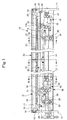
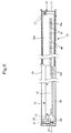
- Fig. 1 is a sectional front view of a web cutting device showing Embodiment 1 of the present invention.
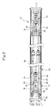
- Fig. 2 is a sectional bottom view of the web cutting device.
- Fig. 3 is a sectional plan view of the web cutting device.
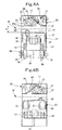
- Fig. 4-A is a sectional view taken along line A-A in Fig. 1 .
- Fig. 4-B is a sectional view taken along line B-B in Fig. 1 .
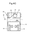
- Fig. 4-C is a sectional view taken along line C-C in Fig. 1 .
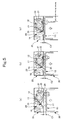
- Figs. 5(a) to 5(c) are operating state views of the web cutting device, in which Fig. 5(a) shows the position of a knife at the initial stage of pressing by a knock bolt, Fig. 5(b) shows the position of the knife in the course of pressing by the knock bolt, and Fig. 5(c) shows the position of the knife when cutting a web while the knock bolt is pressing the knife.
- a web cutting device 10 of a rotary offset printing press has a cutting blade support member 12 pivotably installed between right and left side frames 11.
- a cutting blade bearing member 13 is located below the cutting blade support member 12, and is supported by front and rear stays 14 as a pair, which are installed between the right and left side frames 11, so as to be rendered ascendable and descendable by right and left drive means 15 as a pair, in other words, so as to be movable by these drive means 15 toward and away from the cutting blade support member 12.
- the cutting blade support member 12 has a body portion (holder) 17 in which a saw blade-like knife (cutting blade) 16 is secured, with its cutting edges protruding, to one side of its prismatic body; support shaft portions 19 annexed to opposite end faces of the body portion 17 and pivotably supported by the side frames 11 via bearings 18; and prismatic lever portions 20 extending on the support shaft portions 19 in a direction orthogonal to the axes thereof and having lower surface parts on one end side against which knock bolts to be described later can be pressed.
- each lever portion 20 In an end face part on one end side of each lever portion 20, there is formed an engaging groove 22 with which a stopper pin (position restricting member) 21 provided protrusively at the side frame 11 can engage at the standby position (see Fig. 5(a) ) and the cutting (force-cutting) position (see Fig. 5(c) ) of the knife 16.
- a spring hook 24 In a side surface part on the other end side of each lever portion 20, there is provided a spring hook 24 for holding a return spring (elastic member) 23 which urges the cutting blade support member 12 (knife 16) toward the standby position in cooperation with the side frame 11.
- a cover 25 entirely shields the cutting blade support member 12, and an opening 26 allowing the cutting edges of the knife 16 to enter and exit is formed in a lower surface part 25a of the cover 25.
- a stay 30 for reinforcing the cover is installed to span the right and left side frames 11.
- the cutting blade bearing member 13 is a casing-shaped cover with an open lower surface.
- a slit (blade receiving portion) 27 corresponding to the opening 26 is formed in a top surface part 13a of the cutting blade bearing member 13.
- the aforementioned knock bolt (operating portion) 28 which can be pressed against the lower surface part on the one end side of the lever portion 20, is screwed to the top surface part 13a of the cutting blade bearing member 13 via a nut 29.
- the drive means 15 is provided in two sets (optionally, three sets or more) in the width direction of the web W, each of the sets being composed of front and rear L-shaped levers 31 as a pair which connect the front and rear stays 14 as a pair spanning the side frames 11 to the cutting blade bearing member 13 positioned above the stays 14; and an air cylinder 32 interposed between intermediate parts of the front and rear L-shaped levers 31 as a pair and the front and rear stays 14 as a pair.
- the front and rear L-shaped levers 31 as a pair have upper end parts joined to side surface parts of the cutting blade bearing member 13 by separate pins 33, and have lower end parts joined to support plate portions 35 of the front and rear stays 14 as a pair by the same support shaft 34.
- the leading end of a piston rod of the air cylinder 32 is joined to intermediate parts of the front and rear L-shaped levers 31 as a pair by the same support shaft 36, whereas the base end of a head of the air cylinder 32 is joined to the front and rear stays 14 as a pair by the same support shaft 37.
- a cover 38 shields the side surfaces and lower surface of the cutting blade bearing member 13 and the drive means 15.
- Air piping 39 allows air to be supplied from an air supply source (not shown) to the air cylinder 32 and to be discharged from the air cylinder 32.
- the air cylinder 32 in the drive means 15 of the web cutting device 10 is contracted during ordinary printing to bring the L-shaped levers 31 into a state indicated by solid lines in Fig. 1 . That is, the cutting blade bearing member 13 is separated from the cutting blade support member 12.
- the cutting blade support member 12 (lever portion 20) is restricted to the standby position by the return spring 23, the stopper pin 21, and the engaging groove 22, as shown in Fig. 4A .
- the air cylinder 32 in the drive means 15 is extended to pivot the L-shaped levers 31 counterclockwise about the support shaft 34 so that the L-shaped levers 31 are brought from the state indicated by the solid lines into a state indicated by chain lines in Fig. 1 .
- the cutting blade bearing member 13 obliquely ascends (is lifted) as in a so-called parallel link to approach the cutting blade support member 12, exhibiting behaviors as shown in Figs. 5(a) to 5(c) .
- the aforementioned clearance C which is the passage space for the passage of the web W narrows over time.
- the knock bolt 28 is pressed against the cutting blade support member 12 (lever portion 20).
- the present embodiment features a simple configuration in which the cutting blade bearing member 13 is approached and moved to the cutting blade support member 12 and, at a later stage of this movement, the cutting blade support member 12 is pivoted by the knock bolt 28. Because of such a simple configuration, an injury to the operator is prevented, and the web W is reliably cut, whereby the length of the web W wrapping about the blanket cylinder can be minimized.
- Fig. 6 is a sectional plan view of a web cutting device showing Embodiment 2 of the present invention.
- the other features in the present embodiment are the same as those in Embodiment 1.
- the same members as those in Fig. 3 will be assigned the same numerals as those in Fig. 3 , and duplicate explanations will be omitted.
- the following advantages are obtained: During cutting, the web W is held by the sections between the engaging knife holes 40 (i.e., the top surface part 13a), so that the web W does not sag, and perforations are formed accurately. Since the web W is pulled forward, moreover, the web W is reliably cut at the perforated area.
- the present invention is not limited to the foregoing embodiments, but various changes and modifications, such as changes in the structures of the cutting blade support member 12 and the cutting blade bearing member 13, changes in the shapes of the respective members, a change in the number of the drive means, changes in the actuators, and a change in the structure of the operating portion, may be made without departing from the gist of the present invention.
Landscapes
- Life Sciences & Earth Sciences (AREA)
- Forests & Forestry (AREA)
- Engineering & Computer Science (AREA)
- Mechanical Engineering (AREA)
- Details Of Cutting Devices (AREA)
- Inking, Control Or Cleaning Of Printing Machines (AREA)
Abstract
A web cutting device (10), is equipped with a cutting blade (16) for cutting a web (W), and comprises: a cutting blade support member (12) supporting the cutting blade and supported to be pivotable between a standby position and a cutting position; a return spring (23) for urging the cutting blade support member toward the standby position; a stopper pin (21) and an engaging groove (22) for stopping the cutting blade support member at least at the standby position; a cutting blade bearing member (13) provided with a slit (27) for receiving the cutting blade, and a knock bolt (28) for pivoting the cutting blade support member to the cutting position; and drive means (15), composed of an L-shaped lever (31) and an air cylinder (32), for moving the cutting blade bearing member toward and away from the cutting blade support member.
Description
- The present invention relates to a web cutting device of a rotary offset printing press for applying printing to a web.
- With a rotary offset printing press for applying printing to a web, when breakage of the web (paper breakage) occurs, the web wraps around the circumferential surface of a blanket cylinder because of adhesion of ink. This has led to an accident such as damage to a cylinder bearing or a cylinder shaft of the blanket cylinder.
- As disclosed in
Patent Document 1, etc., therefore, a web cutting device for cutting the web at the same time that the breakage of the web is detected is provided on the travel path of the web (for example, between respective printing units and between a final printing unit and a dryer). By so doing, the length of the web wrapping around the blanket cylinder is minimized, whereby an accident such as damage to the cylinder bearing or cylinder shaft of the blanket cylinder has been avoided. - In the web cutting device of
Patent Document 1, as shown inFigs. 7 and8 , anelongated frame 100 is installed to cross the travel direction of a web W, and apassage space 101 for passage of the web W is provided within theframe 100. Thispassage space 101 accommodates ablade 102, anelongated pedestal 103 facing theblade 102, and anapproach mechanism 104 for bringing theblade 102 close to thepedestal 103 within thepassage space 101 in order to cut the web W. - The
approach mechanism 104 includeslink rod assemblies link rod assembly first link rod 107 connected to theframe 100 via afirst support shaft 106, and a second L-shaped link rod 110 joined to thefirst link rod 107 by asecond support shaft 109 at a control joint (connecting portion) 108. Theblade 102 and at least onepress 111 extending parallel to theblade 102 are joined to thesecond link rod 110 in a coupling arrangement via aslot 112 and athird support shaft 113 and asupport shaft 114. At least oneoperating jack 115 is present which has ends joined to the control joints 108 (second support shafts 109) of thelink rod assemblies - According to the above-described configuration, when the web W is to be cut, the
first link rod 107 and thesecond link rod 110 shift from a folded (closed) state to an extended (opened) state as theoperating jack 115 extends. As a result, thepress 111 and theblade 102 descend within thepassage space 101 to approach thepedestal 103. At the very time when thefirst link rod 107 and thesecond link rod 110 have maximally extended (when the spacing between thepress 111 and thepedestal 103 has fully narrowed), theblade 102 jumps downwardly (outwardly) of thepress 111 to cut the web W (see the standby state of the blade inFig. 7 → the cutting state of the blade inFig. 8 ). - In the manner mentioned above, with the web cutting device of
Patent Document 1, at the time of breakage of the web W, the web W is instantaneously cut to minimize the length of the web W wrapping about the blanket cylinder, thereby preventing the occurrence of an accident such as damage to the cylinder bearing or cylinder shaft of the blanket cylinder, and also preventing an operator's hand from being injured by theblade 102 jumping out. - [Patent Document 1] European Patent
0686505 - With the web cutting device of
Patent Document 1, however, theapproach mechanism 104 comprises thelink rod assemblies first link rod 107, thesecond link rod 110, the first tothird support shafts support shaft 114, and theslot 112. Since the structure is thus complicated and the number of the components is great, the problem has arisen that a cost increase is entailed. - Furthermore, holdback may occur at the junction of the first and
second link rods second support shaft 109, the junction of thesecond link rod 110 and thepress 111 connected by thesupport shaft 114, or the junction of thesecond link rod 110 and theblade 102 connected by thethird support shaft 113. Hence, the reliability of the web cutting device has been low. - It is an object of the present invention, therefore, to provide a web cutting device which achieves cost reduction by a simplified structure, ensures operational stability, and enhances the reliability of the device.
- A web cutting device according to the present invention, intended to solve the above-mentioned problems, is a web cutting device equipped with a cutting blade for cutting a web, comprising:
- a cutting blade support member supporting the cutting blade and supported to be pivotable between a standby position and a cutting position;
- an elastic member for urging the cutting blade support member toward the standby position;
- a position restricting member for stopping the cutting blade support member at least at the standby position;
- a cutting blade bearing member provided with a blade receiving portion for receiving the cutting blade, and an operating portion for pivoting the cutting blade support member to the cutting position; and
- drive means for moving the cutting blade bearing member toward and away from the cutting blade support member.
- The cutting blade support member may comprise: a body portion having the cutting blade of a saw blade shape secured thereto; support shaft portions annexed to opposite end parts of the body portion and pivotably supported by side frames via bearings; lever portions which are provided on the support shaft portions to extend in a direction orthogonal to an axis of the body portion, and against one end part of each of which the operating portion can be pressed; engaging grooves which are provided in the one end part of each of the lever portions, and with which stopper pins being the position restricting members provided protrusively at the side frames can engage at the standby position and the cutting position; and spring hooks which are provided in another end part of each of the lever portions, and which hold return springs being the elastic members in cooperation with the side frames.
- The cutting blade support member may be entirely shielded by a cover, and an opening allowing cutting edges of the cutting blade to enter and exit may be formed in a lower surface part of the cover.
- The cutting blade bearing member may be a casing-shaped cover opening downward, and a slit as the blade receiving portion may be formed in a top surface part of the cover.
- The cutting blade support member may support the cutting blade of a saw blade shape, the cutting blade bearing member may be a casing-shaped cover opening downward, and many engaging knife holes as the blade receiving portion may be arranged in a row in a top surface part of the cover in correspondence with sawteeth of the cutting blade.
- At least two of the drive means may be provided in a width direction of the web, and each of the drive means may be composed of an L-shaped lever for connecting a stay, which is provided to span side frames, to the cutting blade bearing member located above the stay, and an air cylinder interposed between an intermediate part of the L-shaped lever and the stay.
- The L-shaped levers may be provided frontward and rearward as a pair, upper end parts of the L-shaped levers may be joined by separate pins to side surface parts of a casing-shaped cover opening downward as the cutting blade bearing member, while lower end parts of the L-shaped levers may be joined by the same support shaft to the stays provided frontward and rearward as a pair, and a leading end of a piston rod of the air cylinder may be joined by the same support shaft to the intermediate parts of the L-shaped levers provided frontward and rearward as a pair, while a base end of a head of the air cylinder may be joined by the same support shaft to the stays provided frontward and rearward as a pair.
- According to the above-described web cutting device concerned with the present invention, the cutting blade bearing member is approached and moved to the cutting blade support member and, at a later stage of this movement, the cutting blade support member is pivoted by the operating portion. Because of such a simple structure, an injury to the operator is prevented, and the web can be reliably cut. The simplification of the structure results in cost reduction. Moreover, the stability of operation is ensured, and the reliability of the device is enhanced.
-
- [
Fig. 1] Fig. 1 is a sectional front view of a web cuttingdevice showing Embodiment 1 of the present invention. - [
Fig. 2] Fig. 2 is a sectional bottom view of the web cutting device. - [
Fig. 3] Fig. 3 is a sectional plan view of the web cutting device. - [
Fig. 4A] Fig. 4-A is a sectional view taken along line A-A inFig. 1 . - [
Fig. 4B] Fig. 4-B is a sectional view taken along line B-B inFig. 1 . - [
Fig. 4C] Fig. 4-C is a sectional view taken along line C-C inFig. 1 . - [
Figs. 5(a) to 5(c) Figs. 5(a) to 5(c) are operating state views of the web cutting device, in whichFig. 5(a) shows the position of a knife when a clearance is 10 mm,Fig. 5(b) shows the position of the knife when it contacts the web, andFig. 5(c) shows the position of the knife when cutting the web, while pressing it down, up to a stopper. - [
Fig. 6] Fig. 6 is a sectional plan view of a web cutting device showing Embodiment 2 of the present invention. - [
Fig. 7] Fig. 7 is a sectional front view of a conventional web cutting device during standby of a blade. - [
Fig. 8] Fig. 8 is a sectional front view of the conventional web cutting device when the blade is cutting a web. - Hereinafter, a web cutting device according to the present invention will be described in detail by embodiments with reference to the accompanying drawings.
-
Fig. 1 is a sectional front view of a web cuttingdevice showing Embodiment 1 of the present invention.Fig. 2 is a sectional bottom view of the web cutting device.Fig. 3 is a sectional plan view of the web cutting device.Fig. 4-A is a sectional view taken along line A-A inFig. 1 .Fig. 4-B is a sectional view taken along line B-B inFig. 1 .Fig. 4-C is a sectional view taken along line C-C inFig. 1 .Figs. 5(a) to 5(c) are operating state views of the web cutting device, in whichFig. 5(a) shows the position of a knife at the initial stage of pressing by a knock bolt,Fig. 5(b) shows the position of the knife in the course of pressing by the knock bolt, andFig. 5(c) shows the position of the knife when cutting a web while the knock bolt is pressing the knife. - As shown in the drawings, a
web cutting device 10 of a rotary offset printing press has a cuttingblade support member 12 pivotably installed between right and left side frames 11. A cuttingblade bearing member 13 is located below the cuttingblade support member 12, and is supported by front and rear stays 14 as a pair, which are installed between the right and left side frames 11, so as to be rendered ascendable and descendable by right and left drive means 15 as a pair, in other words, so as to be movable by these drive means 15 toward and away from the cuttingblade support member 12. - The cutting
blade support member 12 has a body portion (holder) 17 in which a saw blade-like knife (cutting blade) 16 is secured, with its cutting edges protruding, to one side of its prismatic body;support shaft portions 19 annexed to opposite end faces of thebody portion 17 and pivotably supported by the side frames 11 viabearings 18; andprismatic lever portions 20 extending on thesupport shaft portions 19 in a direction orthogonal to the axes thereof and having lower surface parts on one end side against which knock bolts to be described later can be pressed. - In an end face part on one end side of each
lever portion 20, there is formed an engaginggroove 22 with which a stopper pin (position restricting member) 21 provided protrusively at theside frame 11 can engage at the standby position (seeFig. 5(a) ) and the cutting (force-cutting) position (seeFig. 5(c) ) of theknife 16. In a side surface part on the other end side of eachlever portion 20, there is provided aspring hook 24 for holding a return spring (elastic member) 23 which urges the cutting blade support member 12 (knife 16) toward the standby position in cooperation with theside frame 11. - A
cover 25 entirely shields the cuttingblade support member 12, and anopening 26 allowing the cutting edges of theknife 16 to enter and exit is formed in alower surface part 25a of thecover 25. Astay 30 for reinforcing the cover is installed to span the right and left side frames 11. - The cutting
blade bearing member 13 is a casing-shaped cover with an open lower surface. A slit (blade receiving portion) 27 corresponding to theopening 26 is formed in atop surface part 13a of the cuttingblade bearing member 13. The aforementioned knock bolt (operating portion) 28, which can be pressed against the lower surface part on the one end side of thelever portion 20, is screwed to thetop surface part 13a of the cuttingblade bearing member 13 via anut 29. - The drive means 15 is provided in two sets (optionally, three sets or more) in the width direction of the web W, each of the sets being composed of front and rear L-shaped
levers 31 as a pair which connect the front and rear stays 14 as a pair spanning the side frames 11 to the cuttingblade bearing member 13 positioned above thestays 14; and anair cylinder 32 interposed between intermediate parts of the front and rear L-shapedlevers 31 as a pair and the front and rear stays 14 as a pair. - The front and rear L-shaped
levers 31 as a pair have upper end parts joined to side surface parts of the cuttingblade bearing member 13 byseparate pins 33, and have lower end parts joined to supportplate portions 35 of the front and rear stays 14 as a pair by thesame support shaft 34. The leading end of a piston rod of theair cylinder 32 is joined to intermediate parts of the front and rear L-shapedlevers 31 as a pair by thesame support shaft 36, whereas the base end of a head of theair cylinder 32 is joined to the front and rear stays 14 as a pair by thesame support shaft 37. - A
cover 38 shields the side surfaces and lower surface of the cuttingblade bearing member 13 and the drive means 15. Air piping 39 allows air to be supplied from an air supply source (not shown) to theair cylinder 32 and to be discharged from theair cylinder 32. - Because of the above-described features, the
air cylinder 32 in the drive means 15 of theweb cutting device 10 is contracted during ordinary printing to bring the L-shapedlevers 31 into a state indicated by solid lines inFig. 1 . That is, the cuttingblade bearing member 13 is separated from the cuttingblade support member 12. - As a result, a clearance C adequate as a passage space for passage of the web W is ensured, as shown in
Figs. 4A to 4C , between the cutting blade support member 12 (its cover 25) and the cutting blade bearing member 13 (its cover 38), so that the web W can travel therethrough smoothly. - On this occasion, the cutting blade support member 12 (lever portion 20) is restricted to the standby position by the
return spring 23, thestopper pin 21, and the engaginggroove 22, as shown inFig. 4A . - When the
web cutting device 10 cuts the web W in response to the breakage of the web W, theair cylinder 32 in the drive means 15 is extended to pivot the L-shapedlevers 31 counterclockwise about thesupport shaft 34 so that the L-shapedlevers 31 are brought from the state indicated by the solid lines into a state indicated by chain lines inFig. 1 . - By the above-mentioned motion, the cutting
blade bearing member 13 obliquely ascends (is lifted) as in a so-called parallel link to approach the cuttingblade support member 12, exhibiting behaviors as shown inFigs. 5(a) to 5(c) . - That is, as the cutting
blade bearing member 13 ascends, the aforementioned clearance C which is the passage space for the passage of the web W narrows over time. In the end, theknock bolt 28 is pressed against the cutting blade support member 12 (lever portion 20). The clearance C changes from a clearance C1 (C1 = 10 mm, for example) which defines the knife position at the initial stage of pressing by the knock bolt, to a clearance C2 which defines the knife position in the course of pressing by the knock bolt, and to a clearance C3 which defines the knife position when force-cutting upon pressing by the knock bolt. - These changes from the clearances C1 to C2 to C3 are dependent on the protruding height of the
knock bolt 28 determined by the adjustment of the degree of screwing-in of theknock bolt 28. With these clearances C1, C2 and C3, an operator's hand can be prevented from being injured by theknife 16 jumping out from inside thecover 25 for the cuttingblade support member 12. - The present embodiment features a simple configuration in which the cutting
blade bearing member 13 is approached and moved to the cuttingblade support member 12 and, at a later stage of this movement, the cuttingblade support member 12 is pivoted by theknock bolt 28. Because of such a simple configuration, an injury to the operator is prevented, and the web W is reliably cut, whereby the length of the web W wrapping about the blanket cylinder can be minimized. - Consequently, at the time of breakage of the web W, an accident, such as damage to the cylinder bearing or the cylinder shaft of the blanket cylinder, can be avoided. Moreover, the simplification of the structure of the
web cutting device 10 results in cost reduction, and ensures the stability of operation, leading to enhanced reliability. -
Fig. 6 is a sectional plan view of a web cutting device showing Embodiment 2 of the present invention. - This is an embodiment in which instead of the slit (blade receiving portion) 27 formed in the
top surface part 13a of the cuttingblade bearing member 13 inEmbodiment 1, many engaging knife holes (blade receiving portion) 40 are arranged in a row in correspondence withsawteeth 16a of the saw blade-like knife 16. The other features in the present embodiment are the same as those inEmbodiment 1. Thus, the same members as those inFig. 3 will be assigned the same numerals as those inFig. 3 , and duplicate explanations will be omitted. - According to the present embodiment, in addition to the same actions and effects as those in
Embodiment 1, the following advantages are obtained: During cutting, the web W is held by the sections between the engaging knife holes 40 (i.e., thetop surface part 13a), so that the web W does not sag, and perforations are formed accurately. Since the web W is pulled forward, moreover, the web W is reliably cut at the perforated area. - It goes without saying that the present invention is not limited to the foregoing embodiments, but various changes and modifications, such as changes in the structures of the cutting
blade support member 12 and the cuttingblade bearing member 13, changes in the shapes of the respective members, a change in the number of the drive means, changes in the actuators, and a change in the structure of the operating portion, may be made without departing from the gist of the present invention. -
- 10
- Web cutting device
- 11
- Side frame
- 12
- Cutting blade support member
- 13
- Cutting blade bearing member (casing-shaped cover)
- 13a
- Top surface part
- 14
- Stay
- 15
- Drive means
- 16
- Saw blade-like knife (cutting blade)
- 17
- Body portion (holder)
- 18
- Bearing
- 19
- Support shaft portion
- 20
- Lever portion
- 21
- Stopper pin (position restricting member)
- 22
- Engaging groove
- 23
- Return spring
- 24
- Spring hook
- 25
- Cover
- 25a
- Lower surface part
- 26
- Opening
- 27
- Slit (blade receiving portion)
- 28
- Knock bolt
- 29
- Nut
- 30
- Stay
- 31
- L-shaped lever
- 32
- Air cylinder
- 33
- Pin
- 34
- Support shaft
- 35
- Support plate portion
- 36
- Support shaft
- 37
- Support shaft
- 38
- Cover
- 39
- Air piping
- 40
- Engaging knife hole (blade receiving portion)
- C
- Clearance during ordinary printing
- C1
- Clearance at initial stage of pressing by knock bolt
- C2
- Clearance in course of pressing by knock bolt
- C3
- Clearance during force-cutting upon pressing by knock bolt
- W
- Web
Claims (7)
- A web cutting device (10) equipped with a cutting blade (16) for cutting a web (W), comprising:a cutting blade support member (12) supporting the cutting blade and supported to be pivotable between a standby position and a cutting position;an elastic member (23) for urging the cutting blade support member toward the standby position;a position restricting member (21) for stopping the cutting blade support member at least at the standby position;a cutting blade bearing member (13) provided with a blade receiving portion (27, 40) for receiving the cutting blade, and an operating portion (28) for pivoting the cutting blade support member to the cutting position; anddrive means (15) for moving the cutting blade bearing member toward and away from the cutting blade support member.
- The web cutting device according to claim 1, characterized in that the cutting blade support member (12) comprises:
a body portion (17) having the cutting blade of a saw blade shape secured thereto;
support shaft portions (19) annexed to opposite end parts of the body portion and pivotably supported by side frames (11) via bearings (18);
lever portions (20) which are provided on the support shaft portions to extend in a direction orthogonal to an axis of the body portion, and against one end part of each of which the operating portion can be pressed;
engaging grooves (22) which are provided in the one end part of each of the lever portions, and with which stopper pins (21) being the position restricting members provided protrusively at the side frames can engage at the standby position and the cutting position; and
spring hooks (24) which are provided in another end part of each of the lever portions, and which hold return springs (23) being the elastic members in cooperation with the side frames. - The web cutting device according to claim 1 or 2, characterized in that the cutting blade support member (12) is entirely shielded by a cover (25), and an opening (26) allowing cutting edges of the cutting blade to enter and exit is formed in a lower surface part of the cover.
- The web cutting device according to claim 1, characterized in that
the cutting blade bearing member (13) is a casing-shaped cover opening downward, and
a slit (27) as the blade receiving portion is formed in a top surface part of the cover. - The web cutting device according to claim 1, characterized in that
the cutting blade support member (12) supports the cutting blade of a saw blade shape,
the cutting blade bearing member (13) is a casing-shaped cover opening downward, and
many engaging knife holes (40) as the blade receiving portion are arranged in a row in a top surface part of the cover in correspondence with sawteeth (16a) of the cutting blade. - The web cutting device according to claim 1, characterized in that
at least two of the drive means (15) are provided in a width direction of the web, and
each of the drive means is composed of
an L-shaped lever (31) for connecting a stay (14), which is provided to span side frames, to the cutting blade bearing member located above the stay, and
an air cylinder (32) interposed between an intermediate part of the L-shaped lever and the stay. - The web cutting device according to claim 6, characterized in that
the L-shaped levers (31) are provided frontward and rearward as a pair,
upper end parts of the L-shaped levers are joined by separate pins (33) to side surface parts of a casing-shaped cover (13) opening downward as the cutting blade bearing member, while lower end parts of the L-shaped levers are joined by a same support shaft (34) to the stays (14) provided frontward and rearward as a pair, and
a leading end of a piston rod of the air cylinder (32) is joined by a same support shaft (36) to the intermediate parts of the L-shaped levers provided frontward and rearward as a pair, while a base end of a head of the air cylinder is joined by a same support shaft (37) to the stays provided frontward and rearward as a pair.
Applications Claiming Priority (1)
| Application Number | Priority Date | Filing Date | Title |
|---|---|---|---|
| JP2010245969A JP5603203B2 (en) | 2010-11-02 | 2010-11-02 | Web cutting device |
Publications (1)
| Publication Number | Publication Date |
|---|---|
| EP2447069A1 true EP2447069A1 (en) | 2012-05-02 |
Family
ID=44785720
Family Applications (1)
| Application Number | Title | Priority Date | Filing Date |
|---|---|---|---|
| EP20110185405 Withdrawn EP2447069A1 (en) | 2010-11-02 | 2011-10-17 | Web cutting device |
Country Status (4)
| Country | Link |
|---|---|
| US (1) | US20120103158A1 (en) |
| EP (1) | EP2447069A1 (en) |
| JP (1) | JP5603203B2 (en) |
| CN (1) | CN102555426A (en) |
Cited By (1)
| Publication number | Priority date | Publication date | Assignee | Title |
|---|---|---|---|---|
| EP3360829A1 (en) * | 2017-02-10 | 2018-08-15 | Tecnau, Inc. | Emergency stop cutting mechanism for a web rewinding device |
Families Citing this family (5)
| Publication number | Priority date | Publication date | Assignee | Title |
|---|---|---|---|---|
| CN103612469A (en) * | 2013-11-27 | 2014-03-05 | 湖南汉升机器制造有限公司 | Paper breaking device for printing machine |
| CN105480751B (en) * | 2015-12-26 | 2017-08-25 | 宁波市江北宏菱新兴绝缘材料有限公司 | A kind of reinforcing ring coiler device |
| CN105460657B (en) * | 2015-12-26 | 2017-03-29 | 宁波市江北宏菱新兴绝缘材料有限公司 | A kind of glass reinforcing ring wireline reel of convenient cutting |
| CN105479776B (en) * | 2015-12-26 | 2018-01-05 | 宁波市江北宏菱新兴绝缘材料有限公司 | Easily cutting glass reinforcing ring processing unit (plant) |
| JP2024151416A (en) * | 2023-04-12 | 2024-10-25 | 株式会社日本製鋼所 | Rewinding device, film forming device, and rewinding method |
Citations (4)
| Publication number | Priority date | Publication date | Assignee | Title |
|---|---|---|---|---|
| US2186884A (en) * | 1938-06-22 | 1940-01-09 | Wesley P Shomaker | Web cutting mechanism |
| US3831478A (en) * | 1973-07-30 | 1974-08-27 | Eastman Kodak Co | Print cutting mechanism for bordered and borderless prints |
| DE4340836C1 (en) * | 1993-12-01 | 1995-02-16 | Roland Man Druckmasch | Web cutting device for web-fed rotary printing machines |
| EP0686505A1 (en) | 1994-05-26 | 1995-12-13 | Pierre Tesseraud | Web cutting device |
Family Cites Families (5)
| Publication number | Priority date | Publication date | Assignee | Title |
|---|---|---|---|---|
| US4295400A (en) * | 1980-03-31 | 1981-10-20 | Baldwin-Korthe Web Controls, Inc. | Web severing device |
| JPS5997950U (en) * | 1982-12-20 | 1984-07-03 | 三菱重工業株式会社 | Folding machine safety device |
| DE3500719C2 (en) * | 1985-01-11 | 1986-11-06 | M.A.N.- Roland Druckmaschinen AG, 6050 Offenbach | Device for avoiding printing unit damage in a web-fed rotary printing press |
| DE102004016674A1 (en) * | 2004-04-05 | 2005-10-27 | Koenig & Bauer Ag | Cutting and/or feeding web into subsequent processing stage, by triggering correctly registered severing using phase position of cross-cutting device |
| JP4450385B2 (en) * | 2004-04-30 | 2010-04-14 | 株式会社小森コーポレーション | Folding machine |
-
2010
- 2010-11-02 JP JP2010245969A patent/JP5603203B2/en not_active Expired - Fee Related
-
2011
- 2011-10-17 EP EP20110185405 patent/EP2447069A1/en not_active Withdrawn
- 2011-10-25 CN CN2011103282218A patent/CN102555426A/en active Pending
- 2011-11-01 US US13/286,270 patent/US20120103158A1/en not_active Abandoned
Patent Citations (4)
| Publication number | Priority date | Publication date | Assignee | Title |
|---|---|---|---|---|
| US2186884A (en) * | 1938-06-22 | 1940-01-09 | Wesley P Shomaker | Web cutting mechanism |
| US3831478A (en) * | 1973-07-30 | 1974-08-27 | Eastman Kodak Co | Print cutting mechanism for bordered and borderless prints |
| DE4340836C1 (en) * | 1993-12-01 | 1995-02-16 | Roland Man Druckmasch | Web cutting device for web-fed rotary printing machines |
| EP0686505A1 (en) | 1994-05-26 | 1995-12-13 | Pierre Tesseraud | Web cutting device |
Cited By (5)
| Publication number | Priority date | Publication date | Assignee | Title |
|---|---|---|---|---|
| EP3360829A1 (en) * | 2017-02-10 | 2018-08-15 | Tecnau, Inc. | Emergency stop cutting mechanism for a web rewinding device |
| US10464769B2 (en) | 2017-02-10 | 2019-11-05 | Tecnau, Inc. | Emergency stop cutting mechanism for a web rewinding device |
| US10968065B2 (en) | 2017-02-10 | 2021-04-06 | Tecnau, Inc. | Emergency stop cutting mechanism for a web rewinding device |
| US11667487B2 (en) | 2017-02-10 | 2023-06-06 | Tecnau, Inc. | Emergency stop cutting mechanism for a web rewinding device |
| US12122623B2 (en) | 2017-02-10 | 2024-10-22 | Tecnau, Inc. | Emergency stop cutting mechanism for a web rewinding device |
Also Published As
| Publication number | Publication date |
|---|---|
| CN102555426A (en) | 2012-07-11 |
| JP5603203B2 (en) | 2014-10-08 |
| US20120103158A1 (en) | 2012-05-03 |
| JP2012096451A (en) | 2012-05-24 |
Similar Documents
| Publication | Publication Date | Title |
|---|---|---|
| US20120103158A1 (en) | Web cutting device | |
| US4646909A (en) | Apparatus for the separation of pallets on a roller conveyor | |
| KR100552075B1 (en) | Printer | |
| BR112015001092B1 (en) | Variable cutting angle shear and method of operation of a variable cutting angle shear for shearing material | |
| DE602005001511T2 (en) | Detection device for load transmission with a shear pin | |
| US8955298B2 (en) | Mowing finger arrangement | |
| KR100639511B1 (en) | Cutting bean | |
| US7628748B2 (en) | Chopper table | |
| US4295400A (en) | Web severing device | |
| EP2036841B1 (en) | Device for storing and transporting an item | |
| US20060266234A1 (en) | Squeegee device for sieve printing machine | |
| JP5096828B2 (en) | Band cutting device | |
| JP2001220030A (en) | Guide device for guiding a seat and method of operating the guide device | |
| US5740710A (en) | Device for cutting sheets of material | |
| BRPI0510538B1 (en) | DEVICE FOR GRADUALLY DISPLACEMENT OF WORK PARTS | |
| US7845275B2 (en) | Printing unit having a throw-off configuration which allows the risks of damage to the cylinders caused by winding the web of paper to be limited and corresponding printing press | |
| DK2366274T3 (en) | Mejningsfingeranordning | |
| KR20140014479A (en) | Cutting device with blade gap adjust function | |
| JP2777270B2 (en) | Hoisting machine brake release device | |
| US7093353B2 (en) | Automatic unit for inserting hangers from a strip of attached staples | |
| EP1702721A1 (en) | Clamping and centering device for work pieces, having a hook-shaped clamping member | |
| JP5184215B2 (en) | Rail cutting device | |
| JP2004043140A (en) | Elevator safety equipment | |
| US4957142A (en) | Tension lever for negative dobby | |
| US20020157267A1 (en) | Device for longitudinally separating material strips by means of locking brakes on the cutter holders |
Legal Events
| Date | Code | Title | Description |
|---|---|---|---|
| PUAI | Public reference made under article 153(3) epc to a published international application that has entered the european phase |
Free format text: ORIGINAL CODE: 0009012 |
|
| AK | Designated contracting states |
Kind code of ref document: A1 Designated state(s): AL AT BE BG CH CY CZ DE DK EE ES FI FR GB GR HR HU IE IS IT LI LT LU LV MC MK MT NL NO PL PT RO RS SE SI SK SM TR |
|
| AX | Request for extension of the european patent |
Extension state: BA ME |
|
| STAA | Information on the status of an ep patent application or granted ep patent |
Free format text: STATUS: THE APPLICATION IS DEEMED TO BE WITHDRAWN |
|
| 18D | Application deemed to be withdrawn |
Effective date: 20121103 |