EP2446842B1 - Device for stabilising a spine - Google Patents
Device for stabilising a spine Download PDFInfo
- Publication number
- EP2446842B1 EP2446842B1 EP10013960.9A EP10013960A EP2446842B1 EP 2446842 B1 EP2446842 B1 EP 2446842B1 EP 10013960 A EP10013960 A EP 10013960A EP 2446842 B1 EP2446842 B1 EP 2446842B1
- Authority
- EP
- European Patent Office
- Prior art keywords
- sleeve
- screw
- pitch
- external thread
- front portion
- Prior art date
- Legal status (The legal status is an assumption and is not a legal conclusion. Google has not performed a legal analysis and makes no representation as to the accuracy of the status listed.)
- Not-in-force
Links
Images


Classifications
-
- A—HUMAN NECESSITIES
- A61—MEDICAL OR VETERINARY SCIENCE; HYGIENE
- A61B—DIAGNOSIS; SURGERY; IDENTIFICATION
- A61B17/00—Surgical instruments, devices or methods, e.g. tourniquets
- A61B17/56—Surgical instruments or methods for treatment of bones or joints; Devices specially adapted therefor
- A61B17/58—Surgical instruments or methods for treatment of bones or joints; Devices specially adapted therefor for osteosynthesis, e.g. bone plates, screws, setting implements or the like
- A61B17/68—Internal fixation devices, including fasteners and spinal fixators, even if a part thereof projects from the skin
- A61B17/70—Spinal positioners or stabilisers ; Bone stabilisers comprising fluid filler in an implant
-
- A—HUMAN NECESSITIES
- A61—MEDICAL OR VETERINARY SCIENCE; HYGIENE
- A61B—DIAGNOSIS; SURGERY; IDENTIFICATION
- A61B17/00—Surgical instruments, devices or methods, e.g. tourniquets
- A61B17/56—Surgical instruments or methods for treatment of bones or joints; Devices specially adapted therefor
- A61B17/58—Surgical instruments or methods for treatment of bones or joints; Devices specially adapted therefor for osteosynthesis, e.g. bone plates, screws, setting implements or the like
- A61B17/68—Internal fixation devices, including fasteners and spinal fixators, even if a part thereof projects from the skin
- A61B17/686—Plugs, i.e. elements forming interface between bone hole and implant or fastener, e.g. screw
-
- A—HUMAN NECESSITIES
- A61—MEDICAL OR VETERINARY SCIENCE; HYGIENE
- A61B—DIAGNOSIS; SURGERY; IDENTIFICATION
- A61B17/00—Surgical instruments, devices or methods, e.g. tourniquets
- A61B17/56—Surgical instruments or methods for treatment of bones or joints; Devices specially adapted therefor
- A61B17/58—Surgical instruments or methods for treatment of bones or joints; Devices specially adapted therefor for osteosynthesis, e.g. bone plates, screws, setting implements or the like
- A61B17/68—Internal fixation devices, including fasteners and spinal fixators, even if a part thereof projects from the skin
- A61B17/84—Fasteners therefor or fasteners being internal fixation devices
- A61B17/86—Pins or screws or threaded wires; nuts therefor
- A61B17/8625—Shanks, i.e. parts contacting bone tissue
- A61B17/863—Shanks, i.e. parts contacting bone tissue with thread interrupted or changing its form along shank, other than constant taper
-
- A—HUMAN NECESSITIES
- A61—MEDICAL OR VETERINARY SCIENCE; HYGIENE
- A61B—DIAGNOSIS; SURGERY; IDENTIFICATION
- A61B17/00—Surgical instruments, devices or methods, e.g. tourniquets
- A61B17/56—Surgical instruments or methods for treatment of bones or joints; Devices specially adapted therefor
- A61B17/58—Surgical instruments or methods for treatment of bones or joints; Devices specially adapted therefor for osteosynthesis, e.g. bone plates, screws, setting implements or the like
- A61B17/68—Internal fixation devices, including fasteners and spinal fixators, even if a part thereof projects from the skin
- A61B17/84—Fasteners therefor or fasteners being internal fixation devices
- A61B17/86—Pins or screws or threaded wires; nuts therefor
- A61B17/864—Pins or screws or threaded wires; nuts therefor hollow, e.g. with socket or cannulated
-
- A—HUMAN NECESSITIES
- A61—MEDICAL OR VETERINARY SCIENCE; HYGIENE
- A61B—DIAGNOSIS; SURGERY; IDENTIFICATION
- A61B17/00—Surgical instruments, devices or methods, e.g. tourniquets
- A61B17/56—Surgical instruments or methods for treatment of bones or joints; Devices specially adapted therefor
- A61B17/58—Surgical instruments or methods for treatment of bones or joints; Devices specially adapted therefor for osteosynthesis, e.g. bone plates, screws, setting implements or the like
- A61B17/68—Internal fixation devices, including fasteners and spinal fixators, even if a part thereof projects from the skin
- A61B17/84—Fasteners therefor or fasteners being internal fixation devices
- A61B17/86—Pins or screws or threaded wires; nuts therefor
- A61B17/8685—Pins or screws or threaded wires; nuts therefor comprising multiple separate parts
-
- A—HUMAN NECESSITIES
- A61—MEDICAL OR VETERINARY SCIENCE; HYGIENE
- A61B—DIAGNOSIS; SURGERY; IDENTIFICATION
- A61B17/00—Surgical instruments, devices or methods, e.g. tourniquets
- A61B17/56—Surgical instruments or methods for treatment of bones or joints; Devices specially adapted therefor
- A61B17/58—Surgical instruments or methods for treatment of bones or joints; Devices specially adapted therefor for osteosynthesis, e.g. bone plates, screws, setting implements or the like
- A61B17/68—Internal fixation devices, including fasteners and spinal fixators, even if a part thereof projects from the skin
- A61B17/72—Intramedullary pins, nails or other devices
- A61B17/7233—Intramedullary pins, nails or other devices with special means of locking the nail to the bone
- A61B17/7258—Intramedullary pins, nails or other devices with special means of locking the nail to the bone with laterally expanding parts, e.g. for gripping the bone
-
- A—HUMAN NECESSITIES
- A61—MEDICAL OR VETERINARY SCIENCE; HYGIENE
- A61B—DIAGNOSIS; SURGERY; IDENTIFICATION
- A61B17/00—Surgical instruments, devices or methods, e.g. tourniquets
- A61B17/56—Surgical instruments or methods for treatment of bones or joints; Devices specially adapted therefor
- A61B17/58—Surgical instruments or methods for treatment of bones or joints; Devices specially adapted therefor for osteosynthesis, e.g. bone plates, screws, setting implements or the like
- A61B17/68—Internal fixation devices, including fasteners and spinal fixators, even if a part thereof projects from the skin
- A61B17/84—Fasteners therefor or fasteners being internal fixation devices
- A61B17/86—Pins or screws or threaded wires; nuts therefor
- A61B17/866—Material or manufacture
-
- A—HUMAN NECESSITIES
- A61—MEDICAL OR VETERINARY SCIENCE; HYGIENE
- A61B—DIAGNOSIS; SURGERY; IDENTIFICATION
- A61B17/00—Surgical instruments, devices or methods, e.g. tourniquets
- A61B2017/00831—Material properties
- A61B2017/00867—Material properties shape memory effect
-
- A—HUMAN NECESSITIES
- A61—MEDICAL OR VETERINARY SCIENCE; HYGIENE
- A61B—DIAGNOSIS; SURGERY; IDENTIFICATION
- A61B17/00—Surgical instruments, devices or methods, e.g. tourniquets
- A61B17/56—Surgical instruments or methods for treatment of bones or joints; Devices specially adapted therefor
- A61B17/58—Surgical instruments or methods for treatment of bones or joints; Devices specially adapted therefor for osteosynthesis, e.g. bone plates, screws, setting implements or the like
- A61B17/68—Internal fixation devices, including fasteners and spinal fixators, even if a part thereof projects from the skin
- A61B17/84—Fasteners therefor or fasteners being internal fixation devices
- A61B17/86—Pins or screws or threaded wires; nuts therefor
- A61B2017/8655—Pins or screws or threaded wires; nuts therefor with special features for locking in the bone
Description
Die Erfindung betrifft eine Vorrichtung zum Stabilisieren einer Wirbelsäule.The invention relates to a device for stabilizing a spinal column.
Bekannt ist es, eine Wirbelsäule dadurch zu stabilisieren, dass benachbarte Wirbelkörper mittels eines Stabsystems miteinander verbunden werden. Dazu werden in die benachbarten Wirbelkörper vier Pedikelschrauben quer zur Längsachse der Wirbelsäule eingesetzt und jeweils zwei Pedikelschrauben von benachbarten Wirbelkörpern mittels eines Stabs miteinander verbunden. Eine derartige Stabilisierung erfordert einen starken Eingriff beim Patienten und zieht in der Regel ein Weichteiltrauma über eine Länge von 10 cm oder mehr mit sich.It is known to stabilize a spinal column by connecting adjacent vertebral bodies to one another by means of a rod system. For this purpose, four pedicle screws are inserted transversely to the longitudinal axis of the spinal column into the adjacent vertebral bodies and in each case two pedicle screws of adjacent vertebral bodies are connected to one another by means of a rod. Such stabilization requires strong patient intervention and typically involves soft tissue trauma over a 10 cm length or more.
Als Stand der Technik werden die
Die Aufgabe der Erfindung besteht darin, eine Vorrichtung zum Stabilisieren einer Wirbelsäule bereitzustellen, welche mit wenigen Bauteilen eine zuverlässige Stabilisierung der Wirbelsäule bewirkt und insbesondere mit einem nur geringen Weichteiltrauma einsetzbar ist. Die Aufgabe wird erfindungsgemäß durch eine Vorrichtung zum Stabilisieren einer Wirbelsäule mit den Merkmalen des Patentanspruchs 1 oder des Patentanspruchs 7 gelöst.The object of the invention is to provide a device for stabilizing a spinal column, which causes a reliable stabilization of the spine with a few components and can be used in particular with only slight soft tissue trauma. The object is achieved by a device for stabilizing a spine with the features of claim 1 or claim 7.
Vorteilhafte Ausgestaltungen und Weiterbildungen der Erfindung sind in den Unteransprüchen angegeben.Advantageous embodiments and further developments of the invention are specified in the subclaims.
Die erfindungsgemäße Vorrichtung zum Stabilisieren einer Wirbelsäule weist eine Hülse zum Einbringen in einen Wirbelkörper auf, welche in einem Abschnitt ein Außengewinde aufweist, sowie eine Schraube. Die Hülse kann auf einfache Art und Weise implantiert werden und kann in Kombination mit der Schraube eine Stabilisierung zweier benachbarter Wirbelkörper bewirken und insbesondere ein aufwändiges Stabsystem mit mehreren Pedikelschrauben ersetzen. Die Zahl der zu implantierenden Elemente kann somit deutlich verringert werden. Die Hülse und die darin angeordnete Schraube können von dorso-medial durch einen oberen Wirbelkörper und den daran anschließenden Zwischenwirbelraum bis in den benachbarten unteren Wirbelkörper eingeführt werden, wodurch eine zuverlässige Stabilisierung der beiden benachbarten Wirbelkörper gegeneinander erreicht werden kann, jedoch lediglich ein kleiner Zugang im Patienten vonnöten ist, insbesondere ein minimalinvasiver Zutritt ermöglicht wird.The inventive device for stabilizing a spinal column has a sleeve for insertion into a vertebral body, which has an external thread in a section, and a screw. The Sleeve can be implanted in a simple manner and can cause a stabilization of two adjacent vertebral bodies in combination with the screw and in particular replace a complex rod system with multiple pedicle screws. The number of elements to be implanted can thus be significantly reduced. The sleeve and the screw disposed therein can be inserted from dorso-medial through an upper vertebral body and the adjoining intervertebral space to the adjacent lower vertebral body, whereby a reliable stabilization of the two adjacent vertebral bodies against each other can be achieved, but only a small access in the patient is necessary, in particular a minimally invasive access is made possible.
Gemäß der Erfindung weist die Hülse ein erstes Innengewinde mit einer ersten Steigung auf, in welche die Schraube eindrehbar ist. Die Hülse dient dabei zur Stabilisierung der Schraube innerhalb des Wirbelkörpers. Mit Hilfe der Schraube wird eine zuverlässige Stabilisierung zweier benachbarter Wirbelkörper gegeneinander möglich.According to the invention, the sleeve has a first internal thread with a first pitch, into which the screw can be screwed. The sleeve serves to stabilize the screw within the vertebral body. With the help of the screw, a reliable stabilization of two adjacent vertebral bodies against each other is possible.
Gemäß der Erfindung weist die Hülse einen vorderen Abschnitt, einen mittleren Abschnitt und einen hinteren Abschnitt auf, wobei der vordere Abschnitt das Außengewinde aufweist und in dem mittleren Abschnitt Spreizelemente angeordnet sind. Nach Einsetzen der Hülse können die Spreizelemente aufgespreizt werden, um einen der Wirbelkörper, durch welchen die Hülse geführt ist, zu stabilisieren, beispielsweise aufzurichten.According to the invention, the sleeve has a front portion, a middle portion and a rear portion, wherein the front portion has the external thread and in the central portion spreading elements are arranged. After insertion of the sleeve, the spreading elements can be spread open to stabilize one of the vertebral bodies, through which the sleeve is guided, for example, erect.
In dem mittleren Abschnitt der Hülse sind Öffnungen, insbesondere in Form von Schlitzen, angeordnet, welche insbesondere in Längsrichtung der Hülse angeordnet sind, zwischen welchen die Spreizelemente gebildet sind. Diese Ausgestaltung ermöglicht es auf konstruktiv einfache Art und Weise, die Spreizelemente in der Hülse auszubilden.In the central portion of the sleeve openings, in particular in the form of slots, are arranged, which are arranged in particular in the longitudinal direction of the sleeve, between which the spreading elements are formed. This configuration makes it possible in a structurally simple way to form the expansion elements in the sleeve.
Gemäß der Erfindung weist die Hülse das erste Innengewinde in dem vorderen Abschnitt auf, wobei die Schraube einen vorderen Abschnitt mit einem ersten Außengewinde mit einer dritten Steigung und einen hinteren Abschnitt mit einem zweiten Außengewinde mit einer vierten Steigung aufweist, wobei die dritte Steigung der ersten Steigung entspricht und die vierte Steigung von der dritten Steigung verschieden ist. Die Schraube ist dabei insbesondere als Zug- oder Kompressionsschraube ausgebildet und bewirkt beim Eindrehen in die Hülse, dass der vordere Abschnitt gegen den hinteren Abschnitt gezogen wird und dadurch die Spreizelemente aufspreizen. Weiterhin werden die beiden benachbarten Wirbelkörper gegeneinander verspannt und dadurch, beispielsweise in Kombination mit einem Zwischenwirbelimplantat, zuverlässig stabilisiert.According to the invention, the sleeve has the first internal thread in the front portion, the screw having a front portion with a first external thread having a third pitch and a rear portion with a second external thread having a fourth pitch, the third pitch of the first pitch and the fourth slope is different from the third slope. The screw is designed in particular as a pull or compression screw and causes when screwed into the sleeve, that the front portion is pulled against the rear portion and thereby spread the spreading. Furthermore, the two adjacent vertebrae are braced against each other and thereby reliably stabilized, for example in combination with an intervertebral implant.
Vorteilhafterweise sind die Spreizelemente in Umfangsrichtung der Hülse unterschiedlich ausgebildet, um gegebenenfalls der asymmetrischen Anordnung in der Hülse in dem Wirbelkörper und der Notwendigkeit, den Wirbelkörper in unterschiedlichen Richtungen unterschiedlich stark aufzurichten und zu stabilisieren, Rechnung tragen zu können.Advantageously, the spreading elements are formed differently in the circumferential direction of the sleeve, in order to possibly take into account the asymmetrical arrangement in the sleeve in the vertebral body and the need to erect and stabilize the vertebral body differently in different directions.
Vorteilhafterweise weisen die Spreizelemente Sollknickstellen auf, um ein definiertes Aufspreizen der Spreizelemente der Hülse zu ermöglichen.Advantageously, the spreading elements have predetermined bending points in order to allow a defined spreading of the spreading elements of the sleeve.
Vorzugsweise weist die Schraube an ihrem Schraubenschaft einen Anschlag auf, welcher insbesondere konisch ausgebildet ist, sodass das dem Kopf zugewandte Ende der Hülse an den Anschlag anschlägt und die Zugwirkung oder Kompressionswirkung der Schraube unterstützt. Preferably, the screw has a stop on its screw shaft, which is in particular conical, so that the end of the sleeve facing the head abuts against the stop and supports the tensile action or compression effect of the screw.
Gemäß einer bevorzugten Ausführungsform der Erfindung ist die Hülse zumindest in einem mittleren Abschnitt aus einer Memory-Legierung, insbesondere aus Nitinol gefertigt. Die Memory-Legierung ist insbesondere so gewählt, dass sie bei Erreichen der Körpertemperatur ihre Form ändert. Dabei ist insbesondere vorgesehen, dass diese Formänderung ein Aufspreizen vorhandener Spreizelemente bewirkt. Dadurch kann auf eine Schraube verzichtet werden und eine Stabilisierung der beiden benachbarten Wirbelkörper und ein Aufrichten oder Stabilisieren eines der Wirbelkörper ausschließlich durch die Hülse erreicht werden.According to a preferred embodiment of the invention, the sleeve is made at least in a central portion of a memory alloy, in particular nitinol. The memory alloy is particularly chosen so that it changes shape when reaching body temperature. It is provided in particular that this change in shape causes spreading of existing expansion elements. As a result, it is possible to dispense with a screw and stabilize the two adjacent vertebral bodies and erect or stabilize one of the vertebral bodies exclusively through the sleeve.
Das Einsetzen der Hülse und gegebenenfalls einer Schraube wird dadurch vereinfacht, dass die Hülse und die Schraube kannuliert ausgebildet sind, um zunächst einen Führungsdraht einführen zu können und anschließend entlang dieses Führungsdrahts die Hülse und gegebenenfalls die Schraube einführen zu können.The insertion of the sleeve and possibly a screw is simplified in that the sleeve and the screw are designed to be able to introduce a guidewire first and then along this guidewire to insert the sleeve and possibly the screw can.
Eine Alternative der Erfindung sieht vor, dass die Hülse das erste Innengewinde in einem hinteren Abschnitt aufweist und dass die Schraube einen vorderen Abschnitt mit einem ersten Außengewinde mit einer dritten Steigung und einen hinteren Abschnitt mit einem zweiten Außengewinde mit einer vierten Steigung aufweist, wobei die vierte Steigung der ersten Steigung entspricht. Auf diese Weise wird es ermöglicht, zunächst lediglich die Schraube in die Wirbelkörper einzuführen und schließlich die Hülse auf den hinteren Abschnitt der Schraube aufzudrehen.An alternative of the invention provides that the sleeve has the first internal thread in a rear portion and that the screw has a front portion with a first external thread with a third pitch and a rear portion with a second external thread with a fourth pitch, the fourth Slope of the first slope corresponds. That's the way it will be allows first to insert only the screw in the vertebral bodies and finally to turn the sleeve on the rear portion of the screw.
Gemäß der Alternative ist die Schraube in einem Bereich zwischen dem vorderen Abschnitt und dem hinteren Abschnitt elastisch ausgebildet. Verbleibt dieser Bereich nach Einbringen der Schraube in die Wirbelsäule im Zwischenwirbelraum zwischen zwei benachbarten Wirbelkörpern, ist es möglich, durch diesen elastischen Bereich eine Bandscheibe zu simulieren, welche durch den vorderen Abschnitt und den hinteren Abschnitt der Schraube in den beiden Wirbelkörpern verankert ist.According to the alternative, the screw is elastically formed in a region between the front portion and the rear portion. If this area remains after inserting the screw into the spinal column in the intervertebral space between two adjacent vertebral bodies, it is possible by means of this elastic area to simulate an intervertebral disc which is anchored in the two vertebral bodies by the front portion and the rear portion of the screw.
Die Erfindung wird anhand der nachfolgenden Figuren ausführlich erläutert. Es zeigt
- Figur 1
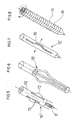
- eine perspektivische Ansicht eines ersten Ausführungsbeispiels einer Hülse,
- Figur 1a
- eine Draufsicht auf das hintere Ende der Hülse gemäß
Figur 1 , - Figur 2
- die Hülse gemäß
Figur 1 mit darin einzuführender Schraube, - Figur 3
- die Hülse gemäß
Figur 1 mit darin eingesetzter Schraube, - Figur 4
- die Hülse gemäß
Figur 1 mit daran angesetztem Eindrehinstrument, - Figur 5
- eine perspektivische Ansicht eines zweiten Ausführungsbeispiels einer Hülse,
- Figur 6
- die Hülse gemäß
Figur 5 in aufgespreiztem Zustand, - Figur 7
- eine Seitenansicht der Hülse gemäß
Figur 5 , - Figur 8
- eine Ausschnittsvergrößerung der Hülse gemäß
Figur 5 , - Figur 9
- eine Seitenansicht eines dritten Ausführungsbeispiels einer Hülse,
Figur 10- die Hülse gemäß
Figur 9 in teilweise geschnittenem Zustand, Figur 11- eine Draufsicht auf das hintere Ende der Hülse gemäß
Figur 9 , Figur 12- die Hülse gemäß
Figur 9 in teilweise eingedrehtem Zustand, Figur 13- die Hülse gemäß
Figur 9 in eingedrehtem Zustand, Figur 14- eine weitere Ansicht der Hülse gemäß
Figur 13 , Figur 15- einen Längsschnitt durch die Hülse gemäß
Figur 9 , Figur 16- eine schematische Darstellung der Hülse gemäß
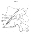
Figur 1 in in einen Wirbelkörper eingesetztem Zustand, Figur 17- eine schematische Darstellung der Hülse gemäß
Figur 9 in in einen Wirbelkörper eingesetztem Zustand, Figur 18- die
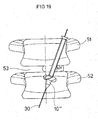
Hülse gemäß Figur 17 in weiter in den Wirbelkörper eingedrehtem Zustand in einer Seitenansicht, - Figur 19
- eine Frontansicht der Hülse gemäß
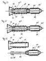
Figur 18 in in den Wirbelkörper eingesetztem Zustand, Figur 20- eine Seitenansicht eines vierten Ausführungsbeispiels einer Hülse mit darin eingesetzter Schraube,
Figur 21- die
Hülse gemäß Figur 20 mit nur teilweise eingesetzter Schraube, Figur 22- die
Hülse gemäß Figur 20 mit derSchraube gemäß Figur 20 , Figur 23- eine schematische Darstellung der Schraube gemäß
Figur 22 in in einen Wirbelkörper eingesetztem Zustand, Figur 24- die
Schraube gemäß Figur 22 , auf welche dieHülse gemäß Figur 22 aufgedreht wird, Figur 25- die
Schraube gemäß Figur 22 , auf welche dieHülse gemäß Figur 22 aufgedreht wird mit einer weiteren Position der Hülse, Figur 26- die
Schraube gemäß Figur 22 , auf welche dieHülse gemäß Figur 22 aufgedreht wird mit einer weiteren Position der Hülse und - Figur 27a, b
- die
Schraube gemäß Figur 22 , auf welche dieHülse gemäß Figur 22 aufgedreht wird mit einer weiteren Position der Hülse.
- FIG. 1
- a perspective view of a first embodiment of a sleeve,
- FIG. 1a
- a plan view of the rear end of the sleeve according to
FIG. 1 . - FIG. 2
- the sleeve according to
FIG. 1 with screw to be inserted therein, - FIG. 3
- the sleeve according to
FIG. 1 with screw inserted therein, - FIG. 4
- the sleeve according to
FIG. 1 with a driver inserted thereon, - FIG. 5
- a perspective view of a second embodiment of a sleeve,
- FIG. 6
- the sleeve according to
FIG. 5 in a spread state, - FIG. 7
- a side view of the sleeve according to
FIG. 5 . - FIG. 8
- an enlarged detail of the sleeve according to
FIG. 5 . - FIG. 9
- a side view of a third embodiment of a sleeve,
- FIG. 10
- the sleeve according to
FIG. 9 in partially cut condition, - FIG. 11
- a plan view of the rear end of the sleeve according to
FIG. 9 . - FIG. 12
- the sleeve according to
FIG. 9 in partially retracted state, - FIG. 13
- the sleeve according to
FIG. 9 in a tightened state, - FIG. 14
- another view of the sleeve according to
FIG. 13 . - FIG. 15
- a longitudinal section through the sleeve according to
FIG. 9 . - FIG. 16
- a schematic representation of the sleeve according to
FIG. 1 in a state used in a vertebral body, - FIG. 17
- a schematic representation of the sleeve according to
FIG. 9 in a state used in a vertebral body, - FIG. 18
- the sleeve according to
FIG. 17 in further rotated in the vertebral body state in a side view, - FIG. 19
- a front view of the sleeve according to
FIG. 18 in the inserted state in the vertebral body, - FIG. 20
- a side view of a fourth embodiment of a sleeve with screw inserted therein,
- FIG. 21
- the sleeve according to
FIG. 20 with only partially inserted screw, - FIG. 22
- the sleeve according to
FIG. 20 with the screw according toFIG. 20 . - FIG. 23
- a schematic representation of the screw according to
FIG. 22 in a state used in a vertebral body, - FIG. 24
- the screw according to
FIG. 22 on which the sleeve according toFIG. 22 is turned on, - FIG. 25
- the screw according to
FIG. 22 on which the sleeve according toFIG. 22 is turned on with another position of the sleeve, - FIG. 26
- the screw according to
FIG. 22 on which the sleeve according toFIG. 22 is turned on with another position of the sleeve and - Figure 27a, b
- the screw according to
FIG. 22 on which the sleeve according toFIG. 22 is turned on with another position of the sleeve.
In den Figuren sind gleiche Teile mit gleichen Bezugsziffern bezeichnet, wobei zur besseren Übersicht nicht sämtliche Bezugsziffern in sämtlichen Figuren angegeben sind.In the figures, the same parts are designated by the same reference numerals, for the sake of clarity, not all reference numerals are given in all figures.
Die
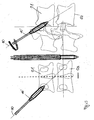
In dem vorderen Bereich 11 der Hülse 10 ist ein erstes Innengewinde angeordnet, welches eine erste Steigung aufweist. In die Hülse 10, insbesondere in das erste Innengewinde der Hülse 10, ist eine Schraube 20 eindrehbar, welche einen Schaft 20a und einen Kopf 20b aufweist. Der Schaft 20a weist einen vorderen Abschnitt 21, einen daran anschließenden mittleren Bereich 22 und einen daran anschließenden hinteren Abschnitt 23 auf, wobei sich an den hinteren Abschnitt 23 der Kopf 20b anschließt. In dem vorderen Abschnitt 21 der Schraube 20 ist ein erstes Außengewinde 24 angeordnet, während in dem hinteren Abschnitt 23 ein zweites Außengewinde 25 angeordnet ist. Das erste Außengewinde 24 weist dabei eine dritte Steigung auf, während das zweite Außengewinde 25 eine vierte Steigung aufweist. Die dritte Steigung des ersten Außengewindes 24 entspricht jedoch insbesondere der ersten Steigung des ersten Innengewindes der Hülse 10. Die dritte Steigung und die vierte Steigung sind dabei unterschiedlich gewählt, sodass die Schraube 20 als Zug- oder Kompressionsschraube wirkt. Wenn die Schraube 20 in die Hülse 10 eingedreht wird, wie insbesondere in
Die Hülse 10 kann auch lediglich den vorderen Abschnitt 11 mit dem Außengewinde 14 aufweisen, ohne die daran anschließenden mittleren und hinteren Bereiche 12, 13 (nicht dargestellt), um eine Stabilisierung der Schraube 20 in dem Wirbelkörper zu bewirken.The
Zum Einsetzen der Hülse 10 in Wirbelkörper 51, 52 (vgl.
An dem Schraubenschaft 20a, insbesondere zwischen dem mittleren Bereich 22 und dem hinteren Bereich 23 der Schraube 20, ist ein Anschlag 26 angeordnet, gegen welchen das freie Ende des hinteren Bereichs 13 der Hülse 10 beim Eindrehen der Schraube 20 anschlägt, sodass der vordere Bereich 11 der Hülse 10 gegen den hinteren Bereich 13 der Hülse 10 gezogen werden kann und sich die Spreizelemente 16 in dem mittleren Bereich 12 aufspreizen.On the
Die Schraube 20 ist kannuliert ausgebildet, sodass beim Implantieren zunächst ein Führungsdraht 30 eingebracht werden kann, über welchen anschließend die Hülse 10 und zuletzt die Schraube 20 eingeführt werden kann.The
Die
In den
In den
In den
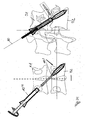
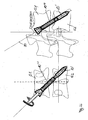
Die
Die Schraube 20' weist einen vorderen Abschnitt 21, einen daran anschließenden mittleren Bereich 22 und einen daran anschließenden hinteren Abschnitt 23 auf. In dem vorderen Abschnitt 21 der Schraube 20 ist ein erstes Außengewinde 24 angeordnet, während in dem hinteren Abschnitt 23 ein zweites Au-βengewinde 25 angeordnet ist. Das erste Außengewinde 24 weist dabei eine dritte Steigung auf, während das zweite Außengewinde 25 eine vierte Steigung aufweist. Die vierte Steigung des zweiten Außengewindes 25 entspricht jedoch insbesondere der ersten Steigung des ersten Innengewindes 16 der Hülse 10. Die dritte Steigung und die vierte Steigung können dabei unterschiedlich gewählt werden.The screw 20 'has a
Wie in den
In einer Ausführungsform ist der mittlere Abschnitt 22 der Schraube 20' elastisch ausgebildet. Wird die Hülse 10''' nur derart weit aufgeschraubt, dass sie im superioren Wirbelkörper 51 verbleibt und lediglich der mittlere Abschnitt 22 der Schraube 20' den Zwischenwirbelraum 53 durchsetzt, besteht die Möglichkeit, die Wirbelkörper 51, 52 gegeneinander zu kippen, zu drehen und relativ zueinander zu bewegen, so dass auf diese Weise eine Bandscheibe simuliert werden kann.In one embodiment, the
- 10, 10', 10''10, 10 ', 10' '
- Hülseshell
- 1111
- Vorderer AbschnittFront section
- 1212
- Mittlerer AbschnittMiddle section
- 1313
- Hinterer AbschnittRear section
- 1414
- Außengewindeexternal thread
- 15, 15', 15''15, 15 ', 15' '
- Schlitzslot
- 1616
- Spreizelementspreader
- 1717
- SollknickstellePredetermined breaking point
- 1818
- Konturcontour
- 2020
- Schraubescrew
- 20a20a
- Schaftshaft
- 20b20b
- Kopfhead
- 2121
- Vorderer AbschnittFront section
- 2222
- Mittlerer AbschnittMiddle section
- 2323
- Hinterer AbschnittRear section
- 2424
- Erstes AußengewindeFirst external thread
- 2525
- Zweites AußengewindeSecond external thread
- 2626
- Anschlagattack
- 3030
- Führungsdrahtguidewire
- 4040
- Eindrehinstrumentscrewing
- 5151
- Wirbelkörpervertebra
- 5252
- Wirbelkörpervertebra
- 5353
- ZwischenwirbelraumIntervertebral space
Claims (7)
- Device for stabilising a spinal column with a sleeve (10, 10', 10") for introduction into a vertebral body (51, 52), having an external thread (14) in one portion (11), and with a screw (20), characterised in that the sleeve (10, 10', 10") has a first internal thread with a first pitch into which the screw (20) can be screwed, that the sleeve (10, 10', 10") has a front portion (11), a central portion (12) and a rear portion (13), wherein the front portion (11) has the external thread (14) and at least one expansion element (16), preferably a plurality of expansion elements (16), is disposed in the central portion (12), that openings in the form of slots (15, 15', 15") disposed in the longitudinal direction of the sleeve (10, 10', 10") are disposed in the central portion (12) of the sleeve (10, 10', 10"), the expansion elements (16) being formed between the said slots, and that either the sleeve (10, 10', 10") has the first internal thread in the front portion (11) and that the screw (20) has a front portion (21) with a first external thread (24) with a third pitch and a rear portion (23) with a second external thread (25) with a fourth pitch, wherein the third pitch corresponds to the first pitch and the fourth pitch differs from the third pitch, or that the sleeve (10'") has the first internal thread in a rear portion (13) and that the screw (20') has a front portion (21) with a first external thread (24) with a third pitch and a rear portion (23) with a second external thread (25) with a fourth pitch, wherein in particular the fourth pitch corresponds to the first pitch.
- Device according to claim 1, characterised in that the expansion elements (16) are constructed differently in the circumferential direction of the sleeve (10, 10', 10").
- Device according to one of claims 1 or 2, characterised in that the expansion elements (16) have predetermined bending points (17).
- Device according to one of the preceding claims, characterised in that the screw (20) has on its shank (20a) a stop (26) which is in particular conical.
- Device according to one of the preceding claims, characterised in that the sleeve (10') is manufactured, at least in the central portion (12), from a memory alloy, in particular from nitinol.
- Device according to one of the preceding claims, characterised in that the sleeve (10, 10', 10") and the screw (20) are cannulated.
- Device for stabilising a spinal column with a sleeve (10"') for introduction into a vertebral body (51, 52), having an external thread (14) in one portion (11), and with a screw (20'), characterised in that the sleeve (10"') has a first internal thread with a first pitch into which the screw (20') can be screwed, that the sleeve (10"') has a front portion (11), a central portion (12) and a rear portion (13), wherein the front portion (11) has the external thread (14) and at least one expansion element (16), preferably a plurality of expansion elements (16), is disposed in the central portion (12), that openings in the form of slots disposed in the longitudinal direction of the sleeve (10"') are disposed in the central portion (12) of the sleeve (10'"), the expansion elements (16) being formed between the said slots, that the sleeve (10"') has the first internal thread in a rear portion (13) and that the screw (20') has a front portion (21) with a first external thread (24) with a third pitch and a rear portion (22) with a second external thread (25) with a fourth pitch, wherein the fourth pitch corresponds to the first pitch, and that the screw (20') is constructed resiliently in a region between the front portion (21) and the rear portion (22).
Priority Applications (2)
| Application Number | Priority Date | Filing Date | Title |
|---|---|---|---|
| ES10013960.9T ES2564415T3 (en) | 2010-10-26 | 2010-10-26 | Device to stabilize a spine |
| EP10013960.9A EP2446842B1 (en) | 2010-10-26 | 2010-10-26 | Device for stabilising a spine |
Applications Claiming Priority (1)
| Application Number | Priority Date | Filing Date | Title |
|---|---|---|---|
| EP10013960.9A EP2446842B1 (en) | 2010-10-26 | 2010-10-26 | Device for stabilising a spine |
Publications (2)
| Publication Number | Publication Date |
|---|---|
| EP2446842A1 EP2446842A1 (en) | 2012-05-02 |
| EP2446842B1 true EP2446842B1 (en) | 2015-12-02 |
Family
ID=43721489
Family Applications (1)
| Application Number | Title | Priority Date | Filing Date |
|---|---|---|---|
| EP10013960.9A Not-in-force EP2446842B1 (en) | 2010-10-26 | 2010-10-26 | Device for stabilising a spine |
Country Status (2)
| Country | Link |
|---|---|
| EP (1) | EP2446842B1 (en) |
| ES (1) | ES2564415T3 (en) |
Families Citing this family (5)
| Publication number | Priority date | Publication date | Assignee | Title |
|---|---|---|---|---|
| EP2676622B1 (en) | 2012-06-18 | 2015-12-30 | Biedermann Technologies GmbH & Co. KG | Bone anchor |
| ES2539501T3 (en) * | 2012-06-18 | 2015-07-01 | Biedermann Technologies Gmbh & Co. Kg | Bone anchor |
| CN104546106B (en) * | 2015-01-26 | 2016-07-13 | 山东省文登整骨医院 | A kind of high holding-force bone screw |
| KR102342948B1 (en) * | 2019-12-30 | 2021-12-24 | 주식회사 엔닥 | Bone fixation screw with expansion and restoration |
| CN111616788B (en) * | 2020-05-23 | 2022-04-26 | 北京庆北医疗器械有限公司 | Bone screw and perforating device with high anti-pulling capacity |
Family Cites Families (6)
| Publication number | Priority date | Publication date | Assignee | Title |
|---|---|---|---|---|
| DE10129490A1 (en) * | 2001-06-21 | 2003-01-02 | Helmut Mueckter | Implantable screw for stabilization of joint or bone fracture, has flexible shaft which interconnects proximal head portion and distal insertion portion of elongated screw body |
| US20100168751A1 (en) * | 2002-03-19 | 2010-07-01 | Anderson D Greg | Method, Implant & Instruments for Percutaneous Expansion of the Spinal Canal |
| US20060052788A1 (en) * | 2003-02-04 | 2006-03-09 | Thelen Sarah L | Expandable fixation devices for minimally invasive surgery |
| US20050143735A1 (en) * | 2003-04-29 | 2005-06-30 | Kyle Richard F. | Double compression unloadable screw system |
| US20080221623A1 (en) * | 2005-10-17 | 2008-09-11 | Gooch Hubert L | Systems and Methods for the Medical Treatment of Structural Tissue |
| WO2009059227A1 (en) * | 2007-11-02 | 2009-05-07 | Stout Medical Group, L.P. | Expandable attachment device and method |
-
2010
- 2010-10-26 EP EP10013960.9A patent/EP2446842B1/en not_active Not-in-force
- 2010-10-26 ES ES10013960.9T patent/ES2564415T3/en active Active
Also Published As
| Publication number | Publication date |
|---|---|
| EP2446842A1 (en) | 2012-05-02 |
| ES2564415T3 (en) | 2016-03-22 |
Similar Documents
| Publication | Publication Date | Title |
|---|---|---|
| EP3117787B1 (en) | Pedicle screw with tulip | |
| EP1570795B1 (en) | Apparatus for dynamic stabilisation of the spine or bones and rod-like element for same | |
| EP3954312B1 (en) | Surgical instrument | |
| EP1339335B1 (en) | Device for fixing bones, particularly vertebral bodies, in relation to one another | |
| DE69923962T2 (en) | BONE IMPLANT WITH A REVERSIBLE FASTENING DEVICE | |
| DE602004011613T2 (en) | EDDY OSTEOSYNTHESIS DEVICE | |
| EP2892451B1 (en) | Pelvic ring implant | |
| EP2515779B1 (en) | Bone plate system for osteosynthesis | |
| DE60214908T2 (en) | JOINT FORT SET-INTERFERENCE SCREW | |
| EP1684652B1 (en) | Bone fixing element and stabilising device comprising one such bone fixing element | |
| EP1753355B1 (en) | Articulated bone screw | |
| DE69630817T2 (en) | WIRBELSÄULENHALTERUNSVORRICHTUNG | |
| DE602005005664T2 (en) | Bone anchoring element | |
| DE102012107056A1 (en) | Surgical instruments | |
| EP2446842B1 (en) | Device for stabilising a spine | |
| DE69814060T2 (en) | MODULAR MARKING NAIL | |
| DE102004009429A1 (en) | Bone anchoring element | |
| WO2005084566A1 (en) | Connecting rod for bone connecting elements | |
| EP2116204B1 (en) | Device for stabilising hollow bone breaks | |
| EP2701622B1 (en) | Closure apparatus for cannulated bone screws | |
| DE202008016697U1 (en) | implant screw | |
| EP2911601B1 (en) | Bone screw | |
| EP2422752A1 (en) | Implant system for the fusion of vertebrae | |
| EP2422710B1 (en) | System for distracting an intervertebral disc space | |
| WO2019192932A1 (en) | Sij implant for the minimally invasive fusion of the sacroiliac joint |
Legal Events
| Date | Code | Title | Description |
|---|---|---|---|
| PUAI | Public reference made under article 153(3) epc to a published international application that has entered the european phase |
Free format text: ORIGINAL CODE: 0009012 |
|
| AK | Designated contracting states |
Kind code of ref document: A1 Designated state(s): AL AT BE BG CH CY CZ DE DK EE ES FI FR GB GR HR HU IE IS IT LI LT LU LV MC MK MT NL NO PL PT RO RS SE SI SK SM TR |
|
| AX | Request for extension of the european patent |
Extension state: BA ME |
|
| 17P | Request for examination filed |
Effective date: 20121031 |
|
| 17Q | First examination report despatched |
Effective date: 20130225 |
|
| GRAP | Despatch of communication of intention to grant a patent |
Free format text: ORIGINAL CODE: EPIDOSNIGR1 |
|
| RIC1 | Information provided on ipc code assigned before grant |
Ipc: A61B 17/70 20060101AFI20150506BHEP Ipc: A61B 17/72 20060101ALI20150506BHEP Ipc: A61B 17/00 20060101ALI20150506BHEP Ipc: A61B 17/86 20060101ALI20150506BHEP Ipc: A61B 17/68 20060101ALI20150506BHEP |
|
| INTG | Intention to grant announced |
Effective date: 20150529 |
|
| GRAS | Grant fee paid |
Free format text: ORIGINAL CODE: EPIDOSNIGR3 |
|
| GRAA | (expected) grant |
Free format text: ORIGINAL CODE: 0009210 |
|
| AK | Designated contracting states |
Kind code of ref document: B1 Designated state(s): AL AT BE BG CH CY CZ DE DK EE ES FI FR GB GR HR HU IE IS IT LI LT LU LV MC MK MT NL NO PL PT RO RS SE SI SK SM TR |
|
| REG | Reference to a national code |
Ref country code: GB Ref legal event code: FG4D Free format text: NOT ENGLISH |
|
| REG | Reference to a national code |
Ref country code: AT Ref legal event code: REF Ref document number: 763229 Country of ref document: AT Kind code of ref document: T Effective date: 20151215 Ref country code: CH Ref legal event code: EP |
|
| REG | Reference to a national code |
Ref country code: IE Ref legal event code: FG4D Free format text: LANGUAGE OF EP DOCUMENT: GERMAN |
|
| REG | Reference to a national code |
Ref country code: DE Ref legal event code: R096 Ref document number: 502010010723 Country of ref document: DE |
|
| REG | Reference to a national code |
Ref country code: CH Ref legal event code: NV Representative=s name: R.A. EGLI AND CO, PATENTANWAELTE, CH |
|
| REG | Reference to a national code |
Ref country code: SE Ref legal event code: TRGR Ref country code: ES Ref legal event code: FG2A Ref document number: 2564415 Country of ref document: ES Kind code of ref document: T3 Effective date: 20160322 |
|
| REG | Reference to a national code |
Ref country code: NL Ref legal event code: FP |
|
| REG | Reference to a national code |
Ref country code: LT Ref legal event code: MG4D |
|
| PG25 | Lapsed in a contracting state [announced via postgrant information from national office to epo] |
Ref country code: NO Free format text: LAPSE BECAUSE OF FAILURE TO SUBMIT A TRANSLATION OF THE DESCRIPTION OR TO PAY THE FEE WITHIN THE PRESCRIBED TIME-LIMIT Effective date: 20160302 Ref country code: HR Free format text: LAPSE BECAUSE OF FAILURE TO SUBMIT A TRANSLATION OF THE DESCRIPTION OR TO PAY THE FEE WITHIN THE PRESCRIBED TIME-LIMIT Effective date: 20151202 Ref country code: LT Free format text: LAPSE BECAUSE OF FAILURE TO SUBMIT A TRANSLATION OF THE DESCRIPTION OR TO PAY THE FEE WITHIN THE PRESCRIBED TIME-LIMIT Effective date: 20151202 |
|
| PG25 | Lapsed in a contracting state [announced via postgrant information from national office to epo] |
Ref country code: FI Free format text: LAPSE BECAUSE OF FAILURE TO SUBMIT A TRANSLATION OF THE DESCRIPTION OR TO PAY THE FEE WITHIN THE PRESCRIBED TIME-LIMIT Effective date: 20151202 Ref country code: PL Free format text: LAPSE BECAUSE OF FAILURE TO SUBMIT A TRANSLATION OF THE DESCRIPTION OR TO PAY THE FEE WITHIN THE PRESCRIBED TIME-LIMIT Effective date: 20151202 Ref country code: RS Free format text: LAPSE BECAUSE OF FAILURE TO SUBMIT A TRANSLATION OF THE DESCRIPTION OR TO PAY THE FEE WITHIN THE PRESCRIBED TIME-LIMIT Effective date: 20151202 Ref country code: GR Free format text: LAPSE BECAUSE OF FAILURE TO SUBMIT A TRANSLATION OF THE DESCRIPTION OR TO PAY THE FEE WITHIN THE PRESCRIBED TIME-LIMIT Effective date: 20160303 Ref country code: LV Free format text: LAPSE BECAUSE OF FAILURE TO SUBMIT A TRANSLATION OF THE DESCRIPTION OR TO PAY THE FEE WITHIN THE PRESCRIBED TIME-LIMIT Effective date: 20151202 |
|
| PG25 | Lapsed in a contracting state [announced via postgrant information from national office to epo] |
Ref country code: IS Free format text: LAPSE BECAUSE OF FAILURE TO SUBMIT A TRANSLATION OF THE DESCRIPTION OR TO PAY THE FEE WITHIN THE PRESCRIBED TIME-LIMIT Effective date: 20151202 |
|
| PG25 | Lapsed in a contracting state [announced via postgrant information from national office to epo] |
Ref country code: CZ Free format text: LAPSE BECAUSE OF FAILURE TO SUBMIT A TRANSLATION OF THE DESCRIPTION OR TO PAY THE FEE WITHIN THE PRESCRIBED TIME-LIMIT Effective date: 20151202 |
|
| PG25 | Lapsed in a contracting state [announced via postgrant information from national office to epo] |
Ref country code: EE Free format text: LAPSE BECAUSE OF FAILURE TO SUBMIT A TRANSLATION OF THE DESCRIPTION OR TO PAY THE FEE WITHIN THE PRESCRIBED TIME-LIMIT Effective date: 20151202 Ref country code: IS Free format text: LAPSE BECAUSE OF FAILURE TO SUBMIT A TRANSLATION OF THE DESCRIPTION OR TO PAY THE FEE WITHIN THE PRESCRIBED TIME-LIMIT Effective date: 20160402 Ref country code: SK Free format text: LAPSE BECAUSE OF FAILURE TO SUBMIT A TRANSLATION OF THE DESCRIPTION OR TO PAY THE FEE WITHIN THE PRESCRIBED TIME-LIMIT Effective date: 20151202 Ref country code: SM Free format text: LAPSE BECAUSE OF FAILURE TO SUBMIT A TRANSLATION OF THE DESCRIPTION OR TO PAY THE FEE WITHIN THE PRESCRIBED TIME-LIMIT Effective date: 20151202 Ref country code: RO Free format text: LAPSE BECAUSE OF FAILURE TO SUBMIT A TRANSLATION OF THE DESCRIPTION OR TO PAY THE FEE WITHIN THE PRESCRIBED TIME-LIMIT Effective date: 20151202 Ref country code: PT Free format text: LAPSE BECAUSE OF FAILURE TO SUBMIT A TRANSLATION OF THE DESCRIPTION OR TO PAY THE FEE WITHIN THE PRESCRIBED TIME-LIMIT Effective date: 20160404 |
|
| REG | Reference to a national code |
Ref country code: DE Ref legal event code: R097 Ref document number: 502010010723 Country of ref document: DE |
|
| PLBE | No opposition filed within time limit |
Free format text: ORIGINAL CODE: 0009261 |
|
| STAA | Information on the status of an ep patent application or granted ep patent |
Free format text: STATUS: NO OPPOSITION FILED WITHIN TIME LIMIT |
|
| PG25 | Lapsed in a contracting state [announced via postgrant information from national office to epo] |
Ref country code: DK Free format text: LAPSE BECAUSE OF FAILURE TO SUBMIT A TRANSLATION OF THE DESCRIPTION OR TO PAY THE FEE WITHIN THE PRESCRIBED TIME-LIMIT Effective date: 20151202 |
|
| 26N | No opposition filed |
Effective date: 20160905 |
|
| PG25 | Lapsed in a contracting state [announced via postgrant information from national office to epo] |
Ref country code: SI Free format text: LAPSE BECAUSE OF FAILURE TO SUBMIT A TRANSLATION OF THE DESCRIPTION OR TO PAY THE FEE WITHIN THE PRESCRIBED TIME-LIMIT Effective date: 20151202 |
|
| PG25 | Lapsed in a contracting state [announced via postgrant information from national office to epo] |
Ref country code: BE Free format text: LAPSE BECAUSE OF NON-PAYMENT OF DUE FEES Effective date: 20161031 |
|
| PG25 | Lapsed in a contracting state [announced via postgrant information from national office to epo] |
Ref country code: MC Free format text: LAPSE BECAUSE OF FAILURE TO SUBMIT A TRANSLATION OF THE DESCRIPTION OR TO PAY THE FEE WITHIN THE PRESCRIBED TIME-LIMIT Effective date: 20151202 |
|
| REG | Reference to a national code |
Ref country code: FR Ref legal event code: ST Effective date: 20170630 |
|
| PG25 | Lapsed in a contracting state [announced via postgrant information from national office to epo] |
Ref country code: FR Free format text: LAPSE BECAUSE OF NON-PAYMENT OF DUE FEES Effective date: 20161102 |
|
| PG25 | Lapsed in a contracting state [announced via postgrant information from national office to epo] |
Ref country code: LU Free format text: LAPSE BECAUSE OF NON-PAYMENT OF DUE FEES Effective date: 20161026 |
|
| REG | Reference to a national code |
Ref country code: BE Ref legal event code: MM Effective date: 20161031 |
|
| REG | Reference to a national code |
Ref country code: DE Ref legal event code: R082 Ref document number: 502010010723 Country of ref document: DE Representative=s name: BLUMBACH ZINNGREBE PATENTANWAELTE PARTG MBB, DE Ref country code: DE Ref legal event code: R082 Ref document number: 502010010723 Country of ref document: DE Representative=s name: BLUMBACH ZINNGREBE PATENT- UND RECHTSANWAELTE , DE |
|
| PG25 | Lapsed in a contracting state [announced via postgrant information from national office to epo] |
Ref country code: HU Free format text: LAPSE BECAUSE OF FAILURE TO SUBMIT A TRANSLATION OF THE DESCRIPTION OR TO PAY THE FEE WITHIN THE PRESCRIBED TIME-LIMIT; INVALID AB INITIO Effective date: 20101026 Ref country code: CY Free format text: LAPSE BECAUSE OF FAILURE TO SUBMIT A TRANSLATION OF THE DESCRIPTION OR TO PAY THE FEE WITHIN THE PRESCRIBED TIME-LIMIT Effective date: 20151202 |
|
| PG25 | Lapsed in a contracting state [announced via postgrant information from national office to epo] |
Ref country code: TR Free format text: LAPSE BECAUSE OF FAILURE TO SUBMIT A TRANSLATION OF THE DESCRIPTION OR TO PAY THE FEE WITHIN THE PRESCRIBED TIME-LIMIT Effective date: 20151202 Ref country code: MT Free format text: LAPSE BECAUSE OF FAILURE TO SUBMIT A TRANSLATION OF THE DESCRIPTION OR TO PAY THE FEE WITHIN THE PRESCRIBED TIME-LIMIT Effective date: 20151202 Ref country code: MK Free format text: LAPSE BECAUSE OF FAILURE TO SUBMIT A TRANSLATION OF THE DESCRIPTION OR TO PAY THE FEE WITHIN THE PRESCRIBED TIME-LIMIT Effective date: 20151202 |
|
| PG25 | Lapsed in a contracting state [announced via postgrant information from national office to epo] |
Ref country code: BG Free format text: LAPSE BECAUSE OF FAILURE TO SUBMIT A TRANSLATION OF THE DESCRIPTION OR TO PAY THE FEE WITHIN THE PRESCRIBED TIME-LIMIT Effective date: 20151202 |
|
| PG25 | Lapsed in a contracting state [announced via postgrant information from national office to epo] |
Ref country code: AL Free format text: LAPSE BECAUSE OF FAILURE TO SUBMIT A TRANSLATION OF THE DESCRIPTION OR TO PAY THE FEE WITHIN THE PRESCRIBED TIME-LIMIT Effective date: 20151202 |
|
| PGFP | Annual fee paid to national office [announced via postgrant information from national office to epo] |
Ref country code: IE Payment date: 20191021 Year of fee payment: 10 Ref country code: NL Payment date: 20191022 Year of fee payment: 10 Ref country code: SE Payment date: 20191023 Year of fee payment: 10 |
|
| PGFP | Annual fee paid to national office [announced via postgrant information from national office to epo] |
Ref country code: ES Payment date: 20191120 Year of fee payment: 10 Ref country code: IT Payment date: 20191021 Year of fee payment: 10 |
|
| PGFP | Annual fee paid to national office [announced via postgrant information from national office to epo] |
Ref country code: AT Payment date: 20191018 Year of fee payment: 10 |
|
| PGFP | Annual fee paid to national office [announced via postgrant information from national office to epo] |
Ref country code: GB Payment date: 20191023 Year of fee payment: 10 |
|
| REG | Reference to a national code |
Ref country code: SE Ref legal event code: EUG |
|
| REG | Reference to a national code |
Ref country code: NL Ref legal event code: MM Effective date: 20201101 |
|
| REG | Reference to a national code |
Ref country code: AT Ref legal event code: MM01 Ref document number: 763229 Country of ref document: AT Kind code of ref document: T Effective date: 20201026 |
|
| GBPC | Gb: european patent ceased through non-payment of renewal fee |
Effective date: 20201026 |
|
| PG25 | Lapsed in a contracting state [announced via postgrant information from national office to epo] |
Ref country code: NL Free format text: LAPSE BECAUSE OF NON-PAYMENT OF DUE FEES Effective date: 20201101 |
|
| PG25 | Lapsed in a contracting state [announced via postgrant information from national office to epo] |
Ref country code: AT Free format text: LAPSE BECAUSE OF NON-PAYMENT OF DUE FEES Effective date: 20201026 Ref country code: GB Free format text: LAPSE BECAUSE OF NON-PAYMENT OF DUE FEES Effective date: 20201026 Ref country code: SE Free format text: LAPSE BECAUSE OF NON-PAYMENT OF DUE FEES Effective date: 20201027 |
|
| PG25 | Lapsed in a contracting state [announced via postgrant information from national office to epo] |
Ref country code: IT Free format text: LAPSE BECAUSE OF NON-PAYMENT OF DUE FEES Effective date: 20201026 Ref country code: IE Free format text: LAPSE BECAUSE OF NON-PAYMENT OF DUE FEES Effective date: 20201026 |
|
| REG | Reference to a national code |
Ref country code: ES Ref legal event code: FD2A Effective date: 20220128 |
|
| PGFP | Annual fee paid to national office [announced via postgrant information from national office to epo] |
Ref country code: DE Payment date: 20211020 Year of fee payment: 12 |
|
| PGFP | Annual fee paid to national office [announced via postgrant information from national office to epo] |
Ref country code: CH Payment date: 20211022 Year of fee payment: 12 |
|
| PG25 | Lapsed in a contracting state [announced via postgrant information from national office to epo] |
Ref country code: ES Free format text: LAPSE BECAUSE OF NON-PAYMENT OF DUE FEES Effective date: 20201027 |
|
| REG | Reference to a national code |
Ref country code: DE Ref legal event code: R119 Ref document number: 502010010723 Country of ref document: DE |
|
| REG | Reference to a national code |
Ref country code: CH Ref legal event code: PL |
|
| PG25 | Lapsed in a contracting state [announced via postgrant information from national office to epo] |
Ref country code: LI Free format text: LAPSE BECAUSE OF NON-PAYMENT OF DUE FEES Effective date: 20221031 Ref country code: DE Free format text: LAPSE BECAUSE OF NON-PAYMENT OF DUE FEES Effective date: 20230503 Ref country code: CH Free format text: LAPSE BECAUSE OF NON-PAYMENT OF DUE FEES Effective date: 20221031 |