EP2446842A1 - Vorrichtung zum Stabilisieren einer Wirbelsäule - Google Patents
Vorrichtung zum Stabilisieren einer Wirbelsäule Download PDFInfo
- Publication number
- EP2446842A1 EP2446842A1 EP20100013960 EP10013960A EP2446842A1 EP 2446842 A1 EP2446842 A1 EP 2446842A1 EP 20100013960 EP20100013960 EP 20100013960 EP 10013960 A EP10013960 A EP 10013960A EP 2446842 A1 EP2446842 A1 EP 2446842A1
- Authority
- EP
- European Patent Office
- Prior art keywords
- sleeve
- screw
- external thread
- pitch
- figur
- Prior art date
- Legal status (The legal status is an assumption and is not a legal conclusion. Google has not performed a legal analysis and makes no representation as to the accuracy of the status listed.)
- Granted
Links
- 0 CC1(CCC(CC2)C3)C23CC(C*)C[*@]1C=CC Chemical compound CC1(CCC(CC2)C3)C23CC(C*)C[*@]1C=CC 0.000 description 1
Images


Classifications
-
- A—HUMAN NECESSITIES
- A61—MEDICAL OR VETERINARY SCIENCE; HYGIENE
- A61B—DIAGNOSIS; SURGERY; IDENTIFICATION
- A61B17/00—Surgical instruments, devices or methods, e.g. tourniquets
- A61B17/56—Surgical instruments or methods for treatment of bones or joints; Devices specially adapted therefor
- A61B17/58—Surgical instruments or methods for treatment of bones or joints; Devices specially adapted therefor for osteosynthesis, e.g. bone plates, screws, setting implements or the like
- A61B17/68—Internal fixation devices, including fasteners and spinal fixators, even if a part thereof projects from the skin
- A61B17/70—Spinal positioners or stabilisers ; Bone stabilisers comprising fluid filler in an implant
-
- A—HUMAN NECESSITIES
- A61—MEDICAL OR VETERINARY SCIENCE; HYGIENE
- A61B—DIAGNOSIS; SURGERY; IDENTIFICATION
- A61B17/00—Surgical instruments, devices or methods, e.g. tourniquets
- A61B17/56—Surgical instruments or methods for treatment of bones or joints; Devices specially adapted therefor
- A61B17/58—Surgical instruments or methods for treatment of bones or joints; Devices specially adapted therefor for osteosynthesis, e.g. bone plates, screws, setting implements or the like
- A61B17/68—Internal fixation devices, including fasteners and spinal fixators, even if a part thereof projects from the skin
- A61B17/686—Plugs, i.e. elements forming interface between bone hole and implant or fastener, e.g. screw
-
- A—HUMAN NECESSITIES
- A61—MEDICAL OR VETERINARY SCIENCE; HYGIENE
- A61B—DIAGNOSIS; SURGERY; IDENTIFICATION
- A61B17/00—Surgical instruments, devices or methods, e.g. tourniquets
- A61B17/56—Surgical instruments or methods for treatment of bones or joints; Devices specially adapted therefor
- A61B17/58—Surgical instruments or methods for treatment of bones or joints; Devices specially adapted therefor for osteosynthesis, e.g. bone plates, screws, setting implements or the like
- A61B17/68—Internal fixation devices, including fasteners and spinal fixators, even if a part thereof projects from the skin
- A61B17/84—Fasteners therefor or fasteners being internal fixation devices
- A61B17/86—Pins or screws or threaded wires; nuts therefor
- A61B17/8625—Shanks, i.e. parts contacting bone tissue
- A61B17/863—Shanks, i.e. parts contacting bone tissue with thread interrupted or changing its form along shank, other than constant taper
-
- A—HUMAN NECESSITIES
- A61—MEDICAL OR VETERINARY SCIENCE; HYGIENE
- A61B—DIAGNOSIS; SURGERY; IDENTIFICATION
- A61B17/00—Surgical instruments, devices or methods, e.g. tourniquets
- A61B17/56—Surgical instruments or methods for treatment of bones or joints; Devices specially adapted therefor
- A61B17/58—Surgical instruments or methods for treatment of bones or joints; Devices specially adapted therefor for osteosynthesis, e.g. bone plates, screws, setting implements or the like
- A61B17/68—Internal fixation devices, including fasteners and spinal fixators, even if a part thereof projects from the skin
- A61B17/84—Fasteners therefor or fasteners being internal fixation devices
- A61B17/86—Pins or screws or threaded wires; nuts therefor
- A61B17/864—Pins or screws or threaded wires; nuts therefor hollow, e.g. with socket or cannulated
-
- A—HUMAN NECESSITIES
- A61—MEDICAL OR VETERINARY SCIENCE; HYGIENE
- A61B—DIAGNOSIS; SURGERY; IDENTIFICATION
- A61B17/00—Surgical instruments, devices or methods, e.g. tourniquets
- A61B17/56—Surgical instruments or methods for treatment of bones or joints; Devices specially adapted therefor
- A61B17/58—Surgical instruments or methods for treatment of bones or joints; Devices specially adapted therefor for osteosynthesis, e.g. bone plates, screws, setting implements or the like
- A61B17/68—Internal fixation devices, including fasteners and spinal fixators, even if a part thereof projects from the skin
- A61B17/84—Fasteners therefor or fasteners being internal fixation devices
- A61B17/86—Pins or screws or threaded wires; nuts therefor
- A61B17/8685—Pins or screws or threaded wires; nuts therefor comprising multiple separate parts
-
- A—HUMAN NECESSITIES
- A61—MEDICAL OR VETERINARY SCIENCE; HYGIENE
- A61B—DIAGNOSIS; SURGERY; IDENTIFICATION
- A61B17/00—Surgical instruments, devices or methods, e.g. tourniquets
- A61B17/56—Surgical instruments or methods for treatment of bones or joints; Devices specially adapted therefor
- A61B17/58—Surgical instruments or methods for treatment of bones or joints; Devices specially adapted therefor for osteosynthesis, e.g. bone plates, screws, setting implements or the like
- A61B17/68—Internal fixation devices, including fasteners and spinal fixators, even if a part thereof projects from the skin
- A61B17/72—Intramedullary pins, nails or other devices
- A61B17/7233—Intramedullary pins, nails or other devices with special means of locking the nail to the bone
- A61B17/7258—Intramedullary pins, nails or other devices with special means of locking the nail to the bone with laterally expanding parts, e.g. for gripping the bone
-
- A—HUMAN NECESSITIES
- A61—MEDICAL OR VETERINARY SCIENCE; HYGIENE
- A61B—DIAGNOSIS; SURGERY; IDENTIFICATION
- A61B17/00—Surgical instruments, devices or methods, e.g. tourniquets
- A61B17/56—Surgical instruments or methods for treatment of bones or joints; Devices specially adapted therefor
- A61B17/58—Surgical instruments or methods for treatment of bones or joints; Devices specially adapted therefor for osteosynthesis, e.g. bone plates, screws, setting implements or the like
- A61B17/68—Internal fixation devices, including fasteners and spinal fixators, even if a part thereof projects from the skin
- A61B17/84—Fasteners therefor or fasteners being internal fixation devices
- A61B17/86—Pins or screws or threaded wires; nuts therefor
- A61B17/866—Material or manufacture
-
- A—HUMAN NECESSITIES
- A61—MEDICAL OR VETERINARY SCIENCE; HYGIENE
- A61B—DIAGNOSIS; SURGERY; IDENTIFICATION
- A61B17/00—Surgical instruments, devices or methods, e.g. tourniquets
- A61B2017/00831—Material properties
- A61B2017/00867—Material properties shape memory effect
-
- A—HUMAN NECESSITIES
- A61—MEDICAL OR VETERINARY SCIENCE; HYGIENE
- A61B—DIAGNOSIS; SURGERY; IDENTIFICATION
- A61B17/00—Surgical instruments, devices or methods, e.g. tourniquets
- A61B17/56—Surgical instruments or methods for treatment of bones or joints; Devices specially adapted therefor
- A61B17/58—Surgical instruments or methods for treatment of bones or joints; Devices specially adapted therefor for osteosynthesis, e.g. bone plates, screws, setting implements or the like
- A61B17/68—Internal fixation devices, including fasteners and spinal fixators, even if a part thereof projects from the skin
- A61B17/84—Fasteners therefor or fasteners being internal fixation devices
- A61B17/86—Pins or screws or threaded wires; nuts therefor
- A61B2017/8655—Pins or screws or threaded wires; nuts therefor with special features for locking in the bone
Definitions
- the invention relates to a device for stabilizing a spinal column.
- the object of the invention is to provide a device for stabilizing a spinal column, which causes a reliable stabilization of the spine with a few components and can be used in particular with only slight soft tissue trauma.
- the object is achieved by a device for stabilizing a spine with the features of claim 1.
- the inventive device for stabilizing a spinal column has a sleeve for introduction into a vertebral body, which has an external thread in a section.
- the Sleeve can be implanted in a simple manner and can either taken alone or in combination with a screw cause stabilization of two adjacent vertebrae and replace in particular a complex rod system with multiple pedicle screws. The number of elements to be implanted can thus be significantly reduced.
- the sleeve and an optionally disposed therein screw can be inserted from dorso-medial through an upper vertebral body and the adjoining intervertebral space to the adjacent lower vertebral body, whereby a reliable stabilization of the two adjacent vertebrae can be achieved against each other, but only a small access in Patients is needed, in particular a minimally invasive access is made possible.
- the sleeve has a first internal thread with a first pitch, in which a screw can be screwed.
- the sleeve serves to stabilize the screw within the vertebral body. With the help of the screw, a reliable stabilization of two adjacent vertebral bodies against each other is possible.
- the sleeve has a front portion, a middle portion and a rear portion, wherein the front portion has the external thread and in the central portion spreading elements are arranged.
- the spreading elements can be spread open to stabilize one of the vertebral bodies, through which the sleeve is guided, for example, erect.
- openings are arranged in the middle section of the sleeve, which are arranged in particular in the longitudinal direction of the sleeve, between which the spreading elements are formed.
- This configuration makes it possible in a structurally simple way to form the expansion elements in the sleeve.
- the spreading elements are designed differently in the circumferential direction of the sleeve, in order to possibly accommodate the asymmetrical arrangement in the sleeve in the vertebral body and the need to erect and stabilize the vertebral body differently in different directions.
- the spreading elements have predetermined bending points in order to allow a defined spreading of the spreading elements of the sleeve.
- the sleeve has the first internal thread in the front portion, wherein the screw has a front portion with a first external thread with a third pitch and a rear portion with a second external thread with a fourth pitch, in particular the third Slope of the first slope and the fourth slope is different from the third slope.
- the screw is designed in particular as a pull or compression screw and causes when screwed into the sleeve, that the front portion is pulled against the rear portion and thereby spread in particular existing spreading elements.
- the two adjacent vertebrae are braced against each other and thereby reliably stabilized, for example in combination with an intervertebral implant.
- the screw has a stop on its screw shaft, which is in particular conical, so that the end of the sleeve facing the head abuts against the stop and supports the tensile action or compression effect of the screw.
- the sleeve is made at least in a central portion of a memory alloy, in particular nitinol.
- the memory alloy is particularly chosen so that it changes shape when reaching body temperature. It is provided in particular that this change in shape causes spreading of existing expansion elements. As a result, it is possible to dispense with a screw and stabilize the two adjacent vertebral bodies and erect or stabilize one of the vertebral bodies exclusively through the sleeve.
- the insertion of the sleeve and optionally a screw is simplified in that the sleeve and a possibly existing screw are designed to be able to initially introduce a guide wire and then along this guide wire to insert the sleeve and possibly the screw can.
- a preferred embodiment of the invention provides that the sleeve has the first internal thread in a rear portion and that the screw has a front portion with a first external thread with a third pitch and a rear portion with a second external thread with a fourth pitch, in particular the fourth slope of the first slope corresponds. That's the way it will be allows first to insert only the screw in the vertebral bodies and finally to turn the sleeve on the rear portion of the screw.
- the screw is formed elastically in a region between the front portion and the rear portion. If this area remains after inserting the screw into the spinal column in the intervertebral space between two adjacent vertebral bodies, it is possible by means of this elastic area to simulate an intervertebral disc which is anchored in the two vertebral bodies by the front portion and the rear portion of the screw.
- FIGS. 1 to 4 show various views of a first embodiment of a sleeve 10 with a front portion 11, an adjoining central portion 12 and an adjoining rear portion 13.
- the front portion 11 carries an external thread 14.
- the rear portion 13 is smooth or on its outside optionally structured in the longitudinal direction.
- a plurality of slots 15 are arranged in the longitudinal direction of the sleeve 10, between which spreading elements 16 are formed.
- the slots 15 are distributed regularly over the circumference.
- four spreading elements 16 are formed.
- the number of spreading elements 16 can also be higher or lower.
- the spreading elements 16 can also be asymmetrically arranged distributed over the outer circumference of the sleeve 10 and formed.
- a first internal thread is arranged, which has a first pitch.
- a screw 20 can be screwed, which has a shaft 20 a and a head 20 b.
- the shaft 20a has a front Section 21, a subsequent central region 22 and an adjoining rear portion 23, wherein the rear portion 23 of the head 20b connects.
- a first external thread 24 is arranged, while in the rear portion 23, a second external thread 25 is arranged.
- the first external thread 24 has a third pitch, while the second external thread 25 has a fourth pitch.
- the third pitch of the first external thread 24 corresponds in particular to the first pitch of the first internal thread of the sleeve 10.
- the third pitch and the fourth pitch are chosen differently, so that the screw 20 acts as a pull or compression screw.
- the screw 20 is screwed into the sleeve 10, in particular in FIG. 3 can be seen, is pulled by the different slopes of the first and second external thread 24, 25 of the front portion 11 against the rear portion 13, wherein the arranged in the central region of the spreading elements 16 radially outwardly spread.
- the spreading elements 16 have predetermined bending points 17 which are intended to ensure a defined spreading of the spreading elements 16.
- the sleeve 10 may also have only the front portion 11 with the external thread 14, without the adjoining central and rear portions 12, 13 (not shown), to effect a stabilization of the screw 20 in the vertebral body.
- a driver 40 is used for insertion of the sleeve 10 in the vertebral body 51, 52 (see. FIG. 16 ) .
- the sleeve 10 has at its one end, in particular at the free end of the rear portion 13, a non-circular contour 18 (see Fig. La), in which a correspondingly shaped contour engages the Einwindinstruments 40 to screw the sleeve into the vertebral bodies 51, 52.
- a non-circular contour 18 see Fig. La
- the sleeve 10 is screwed through the upper vertebral body 51 into the lower vertebral body 52, wherein the sleeve 10 passes through the intervertebral space 53.
- the central region 12 with the spreading elements 16 comes to lie within the lower vertebral body 52. If the screw 20 is subsequently screwed in, the spreading elements 16 spread apart within the vertebral body 52 in order, for example, to erect and stabilize it.
- a stop 26 is arranged against which the free end of the rear region 13 of the sleeve 10 strikes when the screw 20 is screwed in, so that the front region 11 the sleeve 10 can be pulled against the rear portion 13 of the sleeve 10 and spread the spreading elements 16 in the central region 12.
- the screw 20 is designed to be cannulated, so that a guide wire 30 can first be introduced during implantation, via which the sleeve 10 and finally the screw 20 can subsequently be inserted.
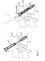
- FIGS. 5 to 8 show a further embodiment of a sleeve 10 ', which can be used without a screw.
- the sleeve 10 ' is made of a memory metal, in particular nitinol, which changes the shape, in particular when the body temperature is reached.
- the sleeve 10 ' also has longitudinally extending slots 15 between which the spreading elements 16 are formed.
- the sleeve 10 "has slots 15" which extend longitudinally but are inclined towards the longitudinal direction twisted against each other, the spread between the slots 15 '' spreading elements 16 spread, and they remain almost against each other in particular when rotating the front portion 11 against the rear portion 13 and form a circumferential bead (see. FIG. 13 ).
- FIGS. 17 to 19 it is shown how the sleeve 10 'comes to rest in the adjacent vertebral bodies 51, 52.
- the sleeve 10 ' is inserted through the upper vertebral body 51, passes through the intervertebral space 53 and is inserted so far that the front portion 11 and the central portion 12 come to lie in the lower vertebral body 52.
- the spreading elements 16 stabilize after spreading the sleeve 10 'the lower vertebral body 52 (see. Figures 18 and 19 ).
- FIGS. 20 to 22 is a further embodiment of a sleeve 10 '''shown with a further embodiment of a screw 20'.
- the FIGS. 23 to 29 show how the sleeve 10 '''and the screw 20' in two adjacent vertebral bodies 51, 52 are introduced.
- FIGS. 20 to 22 show various views of a first embodiment of a sleeve 10 '''with a front portion 11 and an adjoining rear portion 13.
- the front portion 11 carries an external thread 14.
- an internal thread 16 is arranged with a first pitch.
- the rear portion 13 may be conical.
- the screw 20 has a front portion 21, an adjoining central portion 22 and an adjoining rear portion 23.
- a first external thread 24 is arranged, while in the rear portion 23, a second Au- ⁇ engewinde 25 is arranged.
- the first external thread 24 has a third pitch, while the second external thread 25 has a fourth pitch.
- the fourth pitch of the second external thread 25 corresponds in particular to the first pitch of the first internal thread 16 of the sleeve 10.
- the third pitch and the fourth pitch may be selected differently.
- the screw 20 ' in particular along a guide wire 30, inserted into the vertebral bodies 51, 52, wherein the screw 20' is screwed through the upper vertebral body 51 into the lower vertebral body 52, wherein the screw 20 'the disc space 53rd interspersed.
- the central region 12 comes to lie in the intervertebral space 53 (cf. Figures 23 and 24 ).
- the sleeve 10 '''on the screw 20' is rotated (see. FIGS. 24 to 27 ).
- the second external thread engages 25 of the screw 20 'in the internal thread 16 of the sleeve 10''' a.
- the sleeve 10 ''' can in particular be screwed in so far that a stop 26 of the screw 20' against the distal edge of the sleeve 10 '''is pulled and then the vertebral bodies 51, 52 are distracted (see. FIG. 24 . 25 and 26 ).
- the sleeve 10 ''' only be screwed so far that it remains in the superior vertebral body 51 and only the central portion 22 of the screw 20' interspersed the intervertebral space 53 (see. FIG. 27 ).
- the central portion 22 of the screw 20 ' is formed elastically. If the sleeve 10 '''only screwed so far that it remains in the superior vertebral body 51 and only the central portion 22 of the screw 20' intersperses the intervertebral space 53, it is possible to tilt the vertebral bodies 51, 52 against each other, to rotate and to move relative to each other, so that in this way an intervertebral disc can be simulated.
Landscapes
- Health & Medical Sciences (AREA)
- Orthopedic Medicine & Surgery (AREA)
- Life Sciences & Earth Sciences (AREA)
- Surgery (AREA)
- Neurology (AREA)
- Heart & Thoracic Surgery (AREA)
- Engineering & Computer Science (AREA)
- Biomedical Technology (AREA)
- Nuclear Medicine, Radiotherapy & Molecular Imaging (AREA)
- Medical Informatics (AREA)
- Molecular Biology (AREA)
- Animal Behavior & Ethology (AREA)
- General Health & Medical Sciences (AREA)
- Public Health (AREA)
- Veterinary Medicine (AREA)
- Prostheses (AREA)
- Surgical Instruments (AREA)
Abstract
Description
- Die Erfindung betrifft eine Vorrichtung zum Stabilisieren einer Wirbelsäule.
- Bekannt ist es, eine Wirbelsäule dadurch zu stabilisieren, dass benachbarte Wirbelkörper mittels eines Stabsystems miteinander verbunden werden. Dazu werden in die benachbarten Wirbelkörper vier Pedikelschrauben quer zur Längsachse der Wirbelsäule eingesetzt und jeweils zwei Pedikelschrauben von benachbarten Wirbelkörpern mittels eines Stabs miteinander verbunden. Eine derartige Stabilisierung erfordert einen starken Eingriff beim Patienten und zieht in der Regel ein Weichteiltrauma über eine Länge von 10 cm oder mehr mit sich.
- Die Aufgabe der Erfindung besteht darin, eine Vorrichtung zum Stabilisieren einer Wirbelsäule bereitzustellen, welche mit wenigen Bauteilen eine zuverlässige Stabilisierung der Wirbelsäule bewirkt und insbesondere mit einem nur geringen Weichteiltrauma einsetzbar ist.
- Die Aufgabe wird erfindungsgemäß gelöst durch eine Vorrichtung zum Stabilisieren einer Wirbelsäule mit den Merkmalen des Patentanspruchs 1.
- Vorteilhafte Ausgestaltungen und Weiterbildungen der Erfindung sind in den Unteransprüchen angegeben.
- Die erfindungsgemäße Vorrichtung zum Stabilisieren einer Wirbelsäule weist eine Hülse zum Einbringen in einen Wirbelkörper auf, welche in einem Abschnitt ein Außengewinde aufweist. Die Hülse kann auf einfache Art und Weise implantiert werden und kann entweder für sich alleine genommen oder in Kombination mit einer Schraube eine Stabilisierung zweier benachbarter Wirbelkörper bewirken und insbesondere ein aufwändiges Stabsystem mit mehreren Pedikelschrauben ersetzen. Die Zahl der zu implantierenden Elemente kann somit deutlich verringert werden. Die Hülse und eine gegebenenfalls darin angeordnete Schraube können von dorso-medial durch einen oberen Wirbelkörper und den daran anschließenden Zwischenwirbelraum bis in den benachbarten unteren Wirbelkörper eingeführt werden, wodurch eine zuverlässige Stabilisierung der beiden benachbarten Wirbelkörper gegeneinander erreicht werden kann, jedoch lediglich ein kleiner Zugang im Patienten vonnöten ist, insbesondere ein minimalinvasiver Zutritt ermöglicht wird.
- Gemäß einer bevorzugten Ausführungsform der Erfindung weist die Hülse ein erstes Innengewinde mit einer ersten Steigung auf, in welche eine Schraube eindrehbar ist. Die Hülse dient dabei zur Stabilisierung der Schraube innerhalb des Wirbelkörpers. Mit Hilfe der Schraube wird eine zuverlässige Stabilisierung zweier benachbarter Wirbelkörper gegeneinander möglich.
- Gemäß einer besonders bevorzugten Ausführungsform der Erfindung weist die Hülse einen vorderen Abschnitt, einen mittleren Abschnitt und einen hinteren Abschnitt auf, wobei der vordere Abschnitt das Außengewinde aufweist und in dem mittleren Abschnitt Spreizelemente angeordnet sind. Nach Einsetzen der Hülse können die Spreizelemente aufgespreizt werden, um einen der Wirbelkörper, durch welchen die Hülse geführt ist, zu stabilisieren, beispielsweise aufzurichten.
- Vorteilhafterweise sind in dem mittleren Abschnitt der Hülse Öffnungen, insbesondere in Form von Schlitzen, angeordnet, welche insbesondere in Längsrichtung der Hülse angeordnet sind, zwischen welchen die Spreizelemente gebildet sind. Diese Ausgestaltung ermöglicht es auf konstruktiv einfache Art und Weise, die Spreizelemente in der Hülse auszubilden.
- Vorteilhafterweise sind die Spreizelemente in Umfangsrichtung der Hülse unterschiedlich ausgebildet, um gegebenenfalls der asymmetrischen Anordnung in der Hülse in dem Wirbelkörper und der Notwendigkeit, den Wirbelkörper in unterschiedlichen Richtungen unterschiedlich stark aufzurichten und zu stabilisieren, Rechnung tragen zu können.
- Vorteilhafterweise weisen die Spreizelemente Sollknickstellen auf, um ein definiertes Aufspreizen der Spreizelemente der Hülse zu ermöglichen.
- Gemäß einer bevorzugten Ausführungsform der Erfindung weist die Hülse das erste Innengewinde in dem vorderen Abschnitt auf, wobei die Schraube einen vorderen Abschnitt mit einem ersten Außengewinde mit einer dritten Steigung und einen hinteren Abschnitt mit einem zweiten Außengewinde mit einer vierten Steigung aufweist, wobei insbesondere die dritte Steigung der ersten Steigung entspricht und die vierte Steigung von der dritten Steigung verschieden ist. Die Schraube ist dabei insbesondere als Zug- oder Kompressionsschraube ausgebildet und bewirkt beim Eindrehen in die Hülse, dass der vordere Abschnitt gegen den hinteren Abschnitt gezogen wird und dadurch insbesondere vorhandene Spreizelemente aufspreizen. Weiterhin werden die beiden benachbarten Wirbelkörper gegeneinander verspannt und dadurch, beispielsweise in Kombination mit einem Zwischenwirbelimplantat, zuverlässig stabilisiert. Vorzugsweise weist die Schraube an ihrem Schraubenschaft einen Anschlag auf, welcher insbesondere konisch ausgebildet ist, sodass das dem Kopf zugewandte Ende der Hülse an den Anschlag anschlägt und die Zugwirkung oder Kompressionswirkung der Schraube unterstützt.
- Gemäß einer bevorzugten Ausführungsform der Erfindung ist die Hülse zumindest in einem mittleren Abschnitt aus einer Memory-Legierung, insbesondere aus Nitinol gefertigt. Die Memory-Legierung ist insbesondere so gewählt, dass sie bei Erreichen der Körpertemperatur ihre Form ändert. Dabei ist insbesondere vorgesehen, dass diese Formänderung ein Aufspreizen vorhandener Spreizelemente bewirkt. Dadurch kann auf eine Schraube verzichtet werden und eine Stabilisierung der beiden benachbarten Wirbelkörper und ein Aufrichten oder Stabilisieren eines der Wirbelkörper ausschließlich durch die Hülse erreicht werden.
- Das Einsetzen der Hülse und gegebenenfalls einer Schraube wird dadurch vereinfacht, dass die Hülse und eine eventuell vorhandene Schraube kannuliert ausgebildet sind, um zunächst einen Führungsdraht einführen zu können und anschließend entlang dieses Führungsdrahts die Hülse und gegebenenfalls die Schraube einführen zu können.
- Eine bevorzugte Ausführungsform der Erfindung sieht vor, dassdie Hülse das erste Innengewinde in einem hinteren Abschnitt aufweist und dass die Schraube einen vorderen Abschnitt mit einem ersten Außengewinde mit einer dritten Steigung und einen hinteren Abschnitt mit einem zweiten Außengewinde mit einer vierten Steigung aufweist, wobei insbesondere die vierte Steigung der ersten Steigung entspricht. Auf diese Weise wird es ermöglicht, zunächst lediglich die Schraube in die Wirbelkörper einzuführen und schließlich die Hülse auf den hinteren Abschnitt der Schraube aufzudrehen.
- Gemäß einer besonders bevorzugten Ausführungsform der Erfindung ist die Schraube in einem Bereich zwischen dem vorderen Abschnitt und dem hinteren Abschnitt elastisch ausgebildet. Verbleibt dieser Bereich nach Einbringen der Schraube in die Wirbelsäule im Zwischenwirbelraum zwischen zwei benachbarten Wirbelkörpern, ist es möglich, durch diesen elastischen Bereich eine Bandscheibe zu simulieren, welche durch den vorderen Abschnitt und den hinteren Abschnitt der Schraube in den beiden Wirbelkörpern verankert ist.
- Die Erfindung wird anhand der nachfolgenden Figuren ausführlich erläutert. Es zeigt
- Figur 1
- eine perspektivische Ansicht eines ersten Ausführungsbeispiels einer Hülse,
- Figur 1a
- eine Draufsicht auf das hintere Ende der Hülse gemäß
Figur 1 , - Figur 2
- die Hülse gemäß
Figur 1 mit darin einzuführender Schraube, - Figur 3
- die Hülse gemäß
Figur 1 mit darin eingesetzter Schraube, - Figur 4
- die Hülse gemäß
Figur 1 mit daran angesetztem Eindrehinstrument, - Figur 5
- eine perspektivische Ansicht eines zweiten Ausführungsbeispiels einer Hülse,
- Figur 6
- die Hülse gemäß
Figur 5 in aufgespreiztem Zustand, - Figur 7
- eine Seitenansicht der Hülse gemäß
Figur 5 , - Figur 8
- eine Ausschnittsvergrößerung der Hülse gemäß
Figur 5 , - Figur 9
- eine Seitenansicht eines dritten Ausführungsbeispiels einer Hülse,
- Figur 10
- die Hülse gemäß
Figur 9 in teilweise geschnittenem Zustand, - Figur 11
- eine Draufsicht auf das hintere Ende der Hülse gemäß
Figur 9 , - Figur 12
- die Hülse gemäß
Figur 9 in teilweise eingedrehtem Zustand, - Figur 13
- die Hülse gemäß
Figur 9 in eingedrehtem Zustand, - Figur 14
- eine weitere Ansicht der Hülse gemäß
Figur 13 , - Figur 15
- einen Längsschnitt durch die Hülse gemäß
Figur 9 , - Figur 16
- eine schematische Darstellung der Hülse gemäß
Figur 1 in in einen Wirbelkörper eingesetztem Zustand, - Figur 17
- eine schematische Darstellung der Hülse gemäß
Figur 9 in in einen Wirbelkörper eingesetztem Zustand, - Figur 18
- die Hülse gemäß
Figur 17 in weiter in den Wirbelkörper eingedrehtem Zustand in einer Seitenansicht, - Figur 19
- eine Frontansicht der Hülse gemäß
Figur 18 in in den Wirbelkörper eingesetztem Zustand, - Figur 20
- eine Seitenansicht eines vierten Ausführungsbeispiels einer Hülse mit darin eingesetzter Schraube,
- Figur 21
- die Hülse gemäß
Figur 20 mit nur teilweise eingesetzter Schraube, - Figur 22
- die Hülse gemäß
Figur 20 mit der Schraube gemäßFigur 20 , - Figur 23
- eine schematische Darstellung der Schraube gemäß
Figur 22 in in einen Wirbelkörper eingesetztem Zustand, - Figur 24
- die Schraube gemäß
Figur 22 , auf welche die Hülse gemäßFigur 22 aufgedreht wird, - Figur 25
- die Schraube gemäß
Figur 22 , auf welche die Hülse gemäßFigur 22 aufgedreht wird mit einer weiteren Position der Hülse, - Figur 26
- die Schraube gemäß
Figur 22 , auf welche die Hülse gemäßFigur 22 aufgedreht wird mit einer weiteren Position der Hülse und - Figur 27
- die Schraube gemäß
Figur 22 , auf welche die Hülse gemäßFigur 22 aufgedreht wird mit einer weiteren Position der Hülse. - In den Figuren sind gleiche Teile mit gleichen Bezugsziffern bezeichnet, wobei zur besseren Übersicht nicht sämtliche Bezugsziffern in sämtlichen Figuren angegeben sind.
- Die
Figuren 1 bis 4 zeigen verschiedene Ansichten eines ersten Ausführungsbeispiels einer Hülse 10 mit einem vorderen Abschnitt 11, einem sich daran anschließenden mittleren Bereich 12 und einem sich daran anschließenden hinteren Bereich 13. Der vordere Bereich 11 trägt ein Außengewinde 14. Der hintere Bereich 13 ist auf seiner Außenseite glatt oder gegebenenfalls in Längsrichtung strukturiert ausgebildet. In dem mittleren Bereich sind in Längsrichtung der Hülse 10 mehrere Schlitze 15 angeordnet, zwischen welchen Spreizelemente 16 gebildet sind. Vorliegend sind die Schlitze 15 über den Umfang regelmäßig verteilt angeordnet. Insgesamt werden vier Spreizelemente 16 gebildet. Die Zahl der Spreizelemente 16 kann jedoch auch höher oder niedriger sein. Insbesondere können die Spreizelemente 16 auch unsymmetrisch über den Außenumfang der Hülse 10 verteilt angeordnet und ausgeformt sein. - In dem vorderen Bereich 11 der Hülse 10 ist ein erstes Innengewinde angeordnet, welches eine erste Steigung aufweist. In die Hülse 10, insbesondere in das erste Innengewinde der Hülse 10, ist eine Schraube 20 eindrehbar, welche einen Schaft 20a und einen Kopf 20b aufweist. Der Schaft 20a weist einen vorderen Abschnitt 21, einen daran anschließenden mittleren Bereich 22 und einen daran anschließenden hinteren Abschnitt 23 auf, wobei sich an den hinteren Abschnitt 23 der Kopf 20b anschließt. In dem vorderen Abschnitt 21 der Schraube 20 ist ein erstes Außengewinde 24 angeordnet, während in dem hinteren Abschnitt 23 ein zweites Außengewinde 25 angeordnet ist. Das erste Außengewinde 24 weist dabei eine dritte Steigung auf, während das zweite Außengewinde 25 eine vierte Steigung aufweist. Die dritte Steigung des ersten Außengewindes 24 entspricht jedoch insbesondere der ersten Steigung des ersten Innengewindes der Hülse 10. Die dritte Steigung und die vierte Steigung sind dabei unterschiedlich gewählt, sodass die Schraube 20 als Zug- oder Kompressionsschraube wirkt. Wenn die Schraube 20 in die Hülse 10 eingedreht wird, wie insbesondere in
Figur 3 ersichtlich, wird durch die unterschiedlichen Steigungen des ersten und zweiten Außengewindes 24, 25 der vordere Abschnitt 11 gegen den hinteren Abschnitt 13 gezogen, wobei sich die in der mittleren Bereich angeordneten Spreizelemente 16 nach außen radial aufspreizen. Die Spreizelemente 16 weisen dabei Sollknickstellen 17 auf, die ein definiertes Aufspreizen der Spreizelemente 16 gewährleisten sollen. - Die Hülse 10 kann auch lediglich den vorderen Abschnitt 11 mit dem Außengewinde 14 aufweisen, ohne die daran anschließenden mittleren und hinteren Bereiche 12, 13 (nicht dargestellt), um eine Stabilisierung der Schraube 20 in dem Wirbelkörper zu bewirken.
- Zum Einsetzen der Hülse 10 in Wirbelkörper 51, 52 (vgl.
Figur 16 ) wird ein Eindrehinstrument 40 verwendet. Die Hülse 10 weist dabei an ihrem einen Ende, insbesondere an dem freien Ende des hinteren Abschnitts 13, eine unrunde Kontur 18 (vgl. Fig. la) auf, in welcher eine entsprechend ausgeformte Kontur des Eindrehinstruments 40 eingreift, um die Hülse in die Wirbelkörper 51, 52 einzuschrauben. Wie anhand vonFigur 16 ersichtlich, in welchen zwei benachbarte Wirbelkörper 51, 52 mit einem dazwischen liegenden Zwischenwirbelraum 53 schematisch dargestellt sind, wird die Hülse 10 durch den oberen Wirbelkörper 51 bis in den unteren Wirbelkörper 52 eingedreht, wobei die Hülse 10 den Zwischenwirbelraum 53 durchsetzt. Der mittlere Bereich 12 mit den Aufspreizelementen 16 kommt innerhalb des unteren Wirbelkörpers 52 zu liegen. Wird anschließend die Schraube 20 eingedreht, spreizen sich die Spreizelemente 16 innerhalb des Wirbelkörpers 52 auf, um diesen beispielsweise aufzurichten und zu stabilisieren. - An dem Schraubenschaft 20a, insbesondere zwischen dem mittleren Bereich 22 und dem hinteren Bereich 23 der Schraube 20, ist ein Anschlag 26 angeordnet, gegen welchen das freie Ende des hinteren Bereichs 13 der Hülse 10 beim Eindrehen der Schraube 20 anschlägt, sodass der vordere Bereich 11 der Hülse 10 gegen den hinteren Bereich 13 der Hülse 10 gezogen werden kann und sich die Spreizelemente 16 in dem mittleren Bereich 12 aufspreizen.
- Die Schraube 20 ist kannuliert ausgebildet, sodass beim Implantieren zunächst ein Führungsdraht 30 eingebracht werden kann, über welchen anschließend die Hülse 10 und zuletzt die Schraube 20 eingeführt werden kann.
- Die
Figuren 5 bis 8 zeigen ein weiteres Ausführungsbeispiel einer Hülse 10', welche ohne eine Schraube eingesetzt werden kann. Die Hülse 10' ist aus einem Memory-Metall, insbesondere Nitinol, gefertigt, welches die Form insbesondere bei Erreichen der Körpertemperatur verändert. Die Hülse 10' weist ebenfalls in Längsrichtung verlaufende Schlitze 15 auf, zwischen welchen die Spreizelemente 16 gebildet werden. Nachdem die Hülse 10' in die Wirbelkörper 51, 52 eingesetzt wurde und die Körpertemperatur erreicht wurde, bewegen sich der vordere Abschnitt 11 und der hintere Abschnitt 13 relativ gegeneinander aufeinander zu, sodass in dem mittleren Bereich 12 die Spreizelemente 16 aufgespreizt werden (vgl.Figur 6 ). Dabei ist die Hülse 10' über das Außengewinde 14 des vorderen Bereichs 11 in dem Wirbelkörper 52 stabilisiert. - In den
Figuren 9 bis 15 ist ein drittes Ausführungsbeispiel einer Hülse 10" dargestellt. Die Hülse 10" weist Schlitze 15" auf, welche sich in Längsrichtung erstrecken, jedoch gegen die Längsrichtung geneigt verlaufen. Werden der vordere Bereich 11 und der hintere Bereich 13 aufeinander zu bewegt, und dabei insbesondere gegeneinander verdreht, spreizen sich die zwischen den Schlitzen 15'' gebildeten Spreizelemente 16 auf, wobei sie insbesondere bei Verdrehen des vorderen Abschnitts 11 gegen den hinteren Abschnitt 13 nahezu aneinander anliegen bleiben und einen umlaufenden Wulst bilden (vgl.Figur 13 ). - In den
Figuren 17 bis 19 ist dargestellt, wie die Hülse 10' in den benachbarten Wirbelkörpern 51, 52 zu liegen kommt. Die Hülse 10' wird durch den oberen Wirbelkörper 51 eingeführt, durchsetzt den Zwischenwirbelraum 53 und wird soweit eingeführt, dass der vordere Bereich 11 und der mittlere Bereich 12 in dem unteren Wirbelkörper 52 zu liegen kommen. Die Spreizelemente 16 stabilisieren nach Aufspreizen der Hülse 10' den unteren Wirbelkörper 52 (vgl.Figuren 18 und19 ). - In den
Figuren 20 bis 22 ist ein weiteren Ausführungsbeispiel einer Hülse 10''' mit einem weiteren Ausführungsbeispiel einer Schraube 20' dargestellt. DieFiguren 23 bis 29 zeigen, wie die die Hülse 10''' und die Schraube 20' in zwei benachbarte Wirbelkörper 51, 52 eingebracht werden. - Die
Figuren 20 bis 22 zeigen verschiedene Ansichten eines ersten Ausführungsbeispiels einer Hülse 10''' mit einem vorderen Abschnitt 11 und einem sich daran anschließenden hinteren Bereich 13. Der vordere Bereich 11 trägt ein Außengewinde 14. In dem hinteren Abschnitt 13 ist ein Innengewinde 16 mit einer ersten Steigung angeordnet. Zur besseren Stabilisierung kann der hintere Abschnitt 13 konisch ausgebildet sein. - Die Schraube 20' weist einen vorderen Abschnitt 21, einen daran anschließenden mittleren Bereich 22 und einen daran anschließenden hinteren Abschnitt 23 auf. In dem vorderen Abschnitt 21 der Schraube 20 ist ein erstes Außengewinde 24 angeordnet, während in dem hinteren Abschnitt 23 ein zweites Au-βengewinde 25 angeordnet ist. Das erste Außengewinde 24 weist dabei eine dritte Steigung auf, während das zweite Außengewinde 25 eine vierte Steigung aufweist. Die vierte Steigung des zweiten Außengewindes 25 entspricht jedoch insbesondere der ersten Steigung des ersten Innengewindes 16 der Hülse 10. Die dritte Steigung und die vierte Steigung können dabei unterschiedlich gewählt werden.
- Wie in den
Figuren 23 bis 27 erkennbar, wird zunächst die Schraube 20', insbesondere entlang eines Führungsdrahts 30, in die Wirbelkörper 51, 52 eingeführt, wobei die Schraube 20' durch den oberen Wirbelkörper 51 bis in den unteren Wirbelkörper 52 eingedreht wird, wobei die Schraube 20' den Zwischenwirbelraum 53 durchsetzt. Der mittlere Bereich 12 kommt im Zwischenwirbelraum 53 zu liegen (vgl.Figuren 23 und24 ). Anschließend wird die Hülse 10''' auf die Schraube 20' gedreht (vgl.Figuren 24 bis 27 ). Dabei greift das zweite Außengewinde 25 der Schraube 20' in das Innengewinde 16 der Hülse 10''' ein. Die Hülse 10''' kann insbesondere so weit eingedreht werden, dass ein Anschlag 26 der Schraube 20' gegen den distalen Rand der Hülse 10''' gezogen wird und anschließend die Wirbelkörper 51, 52 distrahiert werden (vgl.Figur 24 ,25 und26 ). Alternativ kann auch die Hülse 10''' nur derart weit aufgeschraubt werden, dass sie im superioren Wirbelkörper 51 verbleibt und lediglich der mittlere Abschnitt 22 der Schraube 20' den Zwischenwirbelraum 53 durchsetzt (vgl.Figur 27 ). - In einer Ausführungsform ist der mittlere Abschnitt 22 der Schraube 20' elastisch ausgebildet. Wird die Hülse 10''' nur derart weit aufgeschraubt, dass sie im superioren Wirbelkörper 51 verbleibt und lediglich der mittlere Abschnitt 22 der Schraube 20' den Zwischenwirbelraum 53 durchsetzt, besteht die Möglichkeit, die Wirbelkörper 51, 52 gegeneinander zu kippen, zu drehen und relativ zueinander zu bewegen, so dass auf diese Weise eine Bandscheibe simuliert werden kann.
-
- 10, 10', 10''
- Hülse
- 11
- Vorderer Abschnitt
- 12
- Mittlerer Abschnitt
- 13
- Hinterer Abschnitt
- 14
- Außengewinde
- 15, 15', 15''
- Schlitz
- 16
- Spreizelement
- 17
- Sollknickstelle
- 18
- Kontur
- 20
- Schraube
- 20a
- Schaft
- 20b
- Kopf
- 21
- Vorderer Abschnitt
- 22
- Mittlerer Abschnitt
- 23
- Hinterer Abschnitt
- 24
- Erstes Außengewinde
- 25
- Zweites Außengewinde
- 26
- Anschlag
- 30
- Führungsdraht
- 40
- Eindrehinstrument
- 51
- Wirbelkörper
- 52
- Wirbelkörper
- 53
- Zwischenwirbelraum
Claims (12)
- Vorrichtung zum Stabilisieren einer Wirbelsäule mit einer Hülse (10, 10', 10'') zum Einbringen in einen Wirbelkörper (51, 52), welche in einem Abschnitt (11) ein Außengewinde (14) aufweist.
- Vorrichtung nach Anspruch 1,
dadurch gekennzeichnet, dass die Hülse (10, 10', 10'') ein erstes Innengewinde mit einer ersten Steigung aufweist, in welches eine Schraube (20) eindrehbar ist. - Vorrichtung nach einem der vorhergehenden Ansprüche,
dadurch gekennzeichnet, dass die Hülse (10, 10', 10'') einen vorderen Abschnitt (11), einen mittleren Abschnitt (12) und einen hinteren Abschnitt (13) aufweist, wobei der vordere Abschnitt (11) das Außengewinde (14) aufweist und in dem mittleren Abschnitt (12) wenigstens ein Spreizelement (16), vorzugsweise mehrere Spreizelemente (16), angeordnet ist. - Vorrichtung nach Anspruch 3,
dadurch gekennzeichnet, dass in dem mittleren Abschnitt (12) der Hülse (10, 10', 10'') Öffnungen, insbesondere in Form von Schlitzen (15, 15', 15''), angeordnet sind, welche insbesondere in Längsrichtung der Hülse (10, 10', 10'') angeordnet sind, zwischen welchen die Spreizelemente (16) gebildet sind. - Vorrichtung nach Anspruch 3 oder 4,
dadurch gekennzeichnet, dass die Spreizelemente (16) in Umfangsrichtung der Hülse (10, 10', 10'') unterschiedlich ausgebildet sind. - Vorrichtung nach einem der Ansprüche 3 bis 5,
dadurch gekennzeichnet, dass die Spreizelemente (16) Sollknickstellen (17) aufweisen. - Vorrichtung nach einem der Ansprüche 2 bis 6,
dadurch gekennzeichnet, dass die Hülse (10, 10', 10'') das erste Innengewinde in dem vorderen Abschnitt (11) aufweist und dass die Schraube (20) einen vorderen Abschnitt (21) mit einem ersten Außengewinde (24) mit einer dritten Steigung und einen hinteren Abschnitt (22) mit einem zweiten Außengewinde (25) mit einer vierten Steigung aufweist, wobei insbesondere die dritte Steigung der ersten Steigung entspricht und die vierte Steigung von der dritten Steigung verschieden ist. - Vorrichtung nach einem der Ansprüche 2 bis 7,
dadurch gekennzeichnet, dass die Schraube (20) an ihrem Schraubenschaft (20a) einen Anschlag (26) aufweist, welcher insbesondere konisch ausgebildet ist. - Vorrichtung nach einem der vorhergehenden Ansprüche,
dadurch gekennzeichnet, dass die Hülse (10') zumindest in dem mittleren Abschnitt (12) aus einer Memory-Legierung, insbesondere aus Nitinol, gefertigt ist. - Vorrichtung nach einem der vorhergehenden Ansprüche,
dadurch gekennzeichnet, dass die Hülse (10, 10', 10'') und eine eventuell vorhandene Schraube (20) kannuliert ausgebildet sind. - Vorrichtung nach einem der Ansprüche 2 bis 10,
dadurch gekennzeichnet, dass die Hülse (10''') das erste Innengewinde in einem hinteren Abschnitt (13) aufweist und dass die Schraube (20') einen vorderen Abschnitt (21) mit einem ersten Außengewinde (24) mit einer dritten Steigung und einen hinteren Abschnitt (22) mit einem zweiten Außengewinde (25) mit einer vierten Steigung aufweist, wobei insbesondere die vierte Steigung der ersten Steigung entspricht. - Vorrichtung nach Anspruch 11,
dadurch gekennzeichnet, dass die Schraube (20') in einem Bereich zwischen dem vorderen Abschnitt (21) und dem hinteren Abschnitt (22) elastisch ausgebildet ist.
Priority Applications (2)
| Application Number | Priority Date | Filing Date | Title |
|---|---|---|---|
| ES10013960.9T ES2564415T3 (es) | 2010-10-26 | 2010-10-26 | Dispositivo para estabilizar una columna vertebral |
| EP10013960.9A EP2446842B1 (de) | 2010-10-26 | 2010-10-26 | Vorrichtung zum Stabilisieren einer Wirbelsäule |
Applications Claiming Priority (1)
| Application Number | Priority Date | Filing Date | Title |
|---|---|---|---|
| EP10013960.9A EP2446842B1 (de) | 2010-10-26 | 2010-10-26 | Vorrichtung zum Stabilisieren einer Wirbelsäule |
Publications (2)
| Publication Number | Publication Date |
|---|---|
| EP2446842A1 true EP2446842A1 (de) | 2012-05-02 |
| EP2446842B1 EP2446842B1 (de) | 2015-12-02 |
Family
ID=43721489
Family Applications (1)
| Application Number | Title | Priority Date | Filing Date |
|---|---|---|---|
| EP10013960.9A Not-in-force EP2446842B1 (de) | 2010-10-26 | 2010-10-26 | Vorrichtung zum Stabilisieren einer Wirbelsäule |
Country Status (2)
| Country | Link |
|---|---|
| EP (1) | EP2446842B1 (de) |
| ES (1) | ES2564415T3 (de) |
Cited By (5)
| Publication number | Priority date | Publication date | Assignee | Title |
|---|---|---|---|---|
| EP2676621A1 (de) * | 2012-06-18 | 2013-12-25 | Biedermann Technologies GmbH & Co. KG | Knochenanker |
| CN104546106A (zh) * | 2015-01-26 | 2015-04-29 | 山东省文登整骨医院 | 一种高把持力骨螺钉 |
| US10010361B2 (en) | 2012-06-18 | 2018-07-03 | Biedermann Technologies Gmbh & Co. Kg | Bone anchor |
| CN111616788A (zh) * | 2020-05-23 | 2020-09-04 | 徐州长风生物科技有限公司 | 一种具有高抗拉拔能力的骨螺钉 |
| KR20210085510A (ko) * | 2019-12-30 | 2021-07-08 | 주식회사 엔닥 | 팽창 복원 기능을 구비한 뼈 고정용 스크류 |
Citations (6)
| Publication number | Priority date | Publication date | Assignee | Title |
|---|---|---|---|---|
| US20020198527A1 (en) * | 2001-06-21 | 2002-12-26 | Helmut Muckter | Implantable screw for stabilization of a joint or a bone fracture |
| US20050143735A1 (en) * | 2003-04-29 | 2005-06-30 | Kyle Richard F. | Double compression unloadable screw system |
| US20060052788A1 (en) * | 2003-02-04 | 2006-03-09 | Thelen Sarah L | Expandable fixation devices for minimally invasive surgery |
| US20080221623A1 (en) * | 2005-10-17 | 2008-09-11 | Gooch Hubert L | Systems and Methods for the Medical Treatment of Structural Tissue |
| US20090131992A1 (en) * | 2007-11-02 | 2009-05-21 | Stout Medical Group, L.P. | Expandable attachment device and method |
| US20100168751A1 (en) * | 2002-03-19 | 2010-07-01 | Anderson D Greg | Method, Implant & Instruments for Percutaneous Expansion of the Spinal Canal |
-
2010
- 2010-10-26 EP EP10013960.9A patent/EP2446842B1/de not_active Not-in-force
- 2010-10-26 ES ES10013960.9T patent/ES2564415T3/es active Active
Patent Citations (6)
| Publication number | Priority date | Publication date | Assignee | Title |
|---|---|---|---|---|
| US20020198527A1 (en) * | 2001-06-21 | 2002-12-26 | Helmut Muckter | Implantable screw for stabilization of a joint or a bone fracture |
| US20100168751A1 (en) * | 2002-03-19 | 2010-07-01 | Anderson D Greg | Method, Implant & Instruments for Percutaneous Expansion of the Spinal Canal |
| US20060052788A1 (en) * | 2003-02-04 | 2006-03-09 | Thelen Sarah L | Expandable fixation devices for minimally invasive surgery |
| US20050143735A1 (en) * | 2003-04-29 | 2005-06-30 | Kyle Richard F. | Double compression unloadable screw system |
| US20080221623A1 (en) * | 2005-10-17 | 2008-09-11 | Gooch Hubert L | Systems and Methods for the Medical Treatment of Structural Tissue |
| US20090131992A1 (en) * | 2007-11-02 | 2009-05-21 | Stout Medical Group, L.P. | Expandable attachment device and method |
Cited By (10)
| Publication number | Priority date | Publication date | Assignee | Title |
|---|---|---|---|---|
| EP2676621A1 (de) * | 2012-06-18 | 2013-12-25 | Biedermann Technologies GmbH & Co. KG | Knochenanker |
| CN103505278A (zh) * | 2012-06-18 | 2014-01-15 | 比德尔曼技术有限责任两合公司 | 骨锚固器 |
| EP2910210A1 (de) * | 2012-06-18 | 2015-08-26 | Biedermann Technologies GmbH & Co. KG | Knochenanker |
| US10010361B2 (en) | 2012-06-18 | 2018-07-03 | Biedermann Technologies Gmbh & Co. Kg | Bone anchor |
| US10092339B2 (en) | 2012-06-18 | 2018-10-09 | Biedermann Technologies Gmbh & Co. Kg | Bone anchor |
| US11116556B2 (en) | 2012-06-18 | 2021-09-14 | Biedermann Technologies Gmbh & Co. Kg | Bone anchor |
| CN104546106A (zh) * | 2015-01-26 | 2015-04-29 | 山东省文登整骨医院 | 一种高把持力骨螺钉 |
| KR20210085510A (ko) * | 2019-12-30 | 2021-07-08 | 주식회사 엔닥 | 팽창 복원 기능을 구비한 뼈 고정용 스크류 |
| CN111616788A (zh) * | 2020-05-23 | 2020-09-04 | 徐州长风生物科技有限公司 | 一种具有高抗拉拔能力的骨螺钉 |
| CN111616788B (zh) * | 2020-05-23 | 2022-04-26 | 北京庆北医疗器械有限公司 | 一种具有高抗拉拔能力的骨螺钉及打孔装置 |
Also Published As
| Publication number | Publication date |
|---|---|
| ES2564415T3 (es) | 2016-03-22 |
| EP2446842B1 (de) | 2015-12-02 |
Similar Documents
| Publication | Publication Date | Title |
|---|---|---|
| EP3117787B1 (de) | Pedikelschraube mit tulpe | |
| EP1570795B1 (de) | Einrichtung zur dynamischen Stabilisierung von Wirbeln oder Knochen und stabförmiges Element dafür | |
| DE69630817T2 (de) | Wirbelsäulenhalterunsvorrichtung | |
| EP1339335B1 (de) | Vorrichtung zur fixation von knochen, insbesondere von wirbelkörpern relativ zueinander | |
| EP3954312B1 (de) | Chirurgisches instrumtent | |
| EP2692304B1 (de) | Chirurgisches Instrumentarium | |
| DE602004011613T2 (de) | Wirbel-osteosynthese-gerät | |
| EP1684652B1 (de) | Knochenverankerungselement und stabilisierungseinrichtung mit einem derartigen knochenverankerungselement | |
| EP1753355B1 (de) | Knochenschraube mit gelenk | |
| DE602005005664T2 (de) | Knochenverankerungselement | |
| EP2446842B1 (de) | Vorrichtung zum Stabilisieren einer Wirbelsäule | |
| DE102011109677B4 (de) | Plattensystem zur zervikalen Stabilisation und Fixation | |
| WO2005084566A1 (de) | Verbindungsstab für knochenverbindungselemente | |
| DE102008017741A1 (de) | Vorrichtung zur Stabilisierung von Röhrenknochenbrüchen | |
| EP3023066A1 (de) | Pedikelschraubensystem und wirbelsäulenstabilisierungssystem | |
| EP2911601B1 (de) | Knochenschraube | |
| DE202012009023U1 (de) | Knochenschraube zur Fixation eines Knochenschrauben-Stabsystems | |
| DE102013001933B4 (de) | Knochenschraube zur Fixation eines Knochenschrauben-Stabsystems | |
| EP2422752A1 (de) | Implantantat-System für die Fusion von Wirbelkörpern | |
| DE102014107495A1 (de) | Knochenschraubensystem | |
| DE202018101800U1 (de) | ISG-Implantat zur minimal-invasiven Fusion des Iliosakralgelenks | |
| EP2768401B1 (de) | Mtv-implantations-set | |
| EP2422710A1 (de) | System zum distrahieren eines Bandscheibenfachs | |
| EP4223241A1 (de) | Dilatator für spinale chirurgie | |
| DE202020105885U1 (de) | Klingenartige Osteosynthesevorrichtung |
Legal Events
| Date | Code | Title | Description |
|---|---|---|---|
| PUAI | Public reference made under article 153(3) epc to a published international application that has entered the european phase |
Free format text: ORIGINAL CODE: 0009012 |
|
| AK | Designated contracting states |
Kind code of ref document: A1 Designated state(s): AL AT BE BG CH CY CZ DE DK EE ES FI FR GB GR HR HU IE IS IT LI LT LU LV MC MK MT NL NO PL PT RO RS SE SI SK SM TR |
|
| AX | Request for extension of the european patent |
Extension state: BA ME |
|
| 17P | Request for examination filed |
Effective date: 20121031 |
|
| 17Q | First examination report despatched |
Effective date: 20130225 |
|
| GRAP | Despatch of communication of intention to grant a patent |
Free format text: ORIGINAL CODE: EPIDOSNIGR1 |
|
| RIC1 | Information provided on ipc code assigned before grant |
Ipc: A61B 17/70 20060101AFI20150506BHEP Ipc: A61B 17/72 20060101ALI20150506BHEP Ipc: A61B 17/00 20060101ALI20150506BHEP Ipc: A61B 17/86 20060101ALI20150506BHEP Ipc: A61B 17/68 20060101ALI20150506BHEP |
|
| INTG | Intention to grant announced |
Effective date: 20150529 |
|
| GRAS | Grant fee paid |
Free format text: ORIGINAL CODE: EPIDOSNIGR3 |
|
| GRAA | (expected) grant |
Free format text: ORIGINAL CODE: 0009210 |
|
| AK | Designated contracting states |
Kind code of ref document: B1 Designated state(s): AL AT BE BG CH CY CZ DE DK EE ES FI FR GB GR HR HU IE IS IT LI LT LU LV MC MK MT NL NO PL PT RO RS SE SI SK SM TR |
|
| REG | Reference to a national code |
Ref country code: GB Ref legal event code: FG4D Free format text: NOT ENGLISH |
|
| REG | Reference to a national code |
Ref country code: AT Ref legal event code: REF Ref document number: 763229 Country of ref document: AT Kind code of ref document: T Effective date: 20151215 Ref country code: CH Ref legal event code: EP |
|
| REG | Reference to a national code |
Ref country code: IE Ref legal event code: FG4D Free format text: LANGUAGE OF EP DOCUMENT: GERMAN |
|
| REG | Reference to a national code |
Ref country code: DE Ref legal event code: R096 Ref document number: 502010010723 Country of ref document: DE |
|
| REG | Reference to a national code |
Ref country code: CH Ref legal event code: NV Representative=s name: R.A. EGLI AND CO, PATENTANWAELTE, CH |
|
| REG | Reference to a national code |
Ref country code: SE Ref legal event code: TRGR Ref country code: ES Ref legal event code: FG2A Ref document number: 2564415 Country of ref document: ES Kind code of ref document: T3 Effective date: 20160322 |
|
| REG | Reference to a national code |
Ref country code: NL Ref legal event code: FP |
|
| REG | Reference to a national code |
Ref country code: LT Ref legal event code: MG4D |
|
| PG25 | Lapsed in a contracting state [announced via postgrant information from national office to epo] |
Ref country code: NO Free format text: LAPSE BECAUSE OF FAILURE TO SUBMIT A TRANSLATION OF THE DESCRIPTION OR TO PAY THE FEE WITHIN THE PRESCRIBED TIME-LIMIT Effective date: 20160302 Ref country code: HR Free format text: LAPSE BECAUSE OF FAILURE TO SUBMIT A TRANSLATION OF THE DESCRIPTION OR TO PAY THE FEE WITHIN THE PRESCRIBED TIME-LIMIT Effective date: 20151202 Ref country code: LT Free format text: LAPSE BECAUSE OF FAILURE TO SUBMIT A TRANSLATION OF THE DESCRIPTION OR TO PAY THE FEE WITHIN THE PRESCRIBED TIME-LIMIT Effective date: 20151202 |
|
| PG25 | Lapsed in a contracting state [announced via postgrant information from national office to epo] |
Ref country code: FI Free format text: LAPSE BECAUSE OF FAILURE TO SUBMIT A TRANSLATION OF THE DESCRIPTION OR TO PAY THE FEE WITHIN THE PRESCRIBED TIME-LIMIT Effective date: 20151202 Ref country code: PL Free format text: LAPSE BECAUSE OF FAILURE TO SUBMIT A TRANSLATION OF THE DESCRIPTION OR TO PAY THE FEE WITHIN THE PRESCRIBED TIME-LIMIT Effective date: 20151202 Ref country code: RS Free format text: LAPSE BECAUSE OF FAILURE TO SUBMIT A TRANSLATION OF THE DESCRIPTION OR TO PAY THE FEE WITHIN THE PRESCRIBED TIME-LIMIT Effective date: 20151202 Ref country code: GR Free format text: LAPSE BECAUSE OF FAILURE TO SUBMIT A TRANSLATION OF THE DESCRIPTION OR TO PAY THE FEE WITHIN THE PRESCRIBED TIME-LIMIT Effective date: 20160303 Ref country code: LV Free format text: LAPSE BECAUSE OF FAILURE TO SUBMIT A TRANSLATION OF THE DESCRIPTION OR TO PAY THE FEE WITHIN THE PRESCRIBED TIME-LIMIT Effective date: 20151202 |
|
| PG25 | Lapsed in a contracting state [announced via postgrant information from national office to epo] |
Ref country code: IS Free format text: LAPSE BECAUSE OF FAILURE TO SUBMIT A TRANSLATION OF THE DESCRIPTION OR TO PAY THE FEE WITHIN THE PRESCRIBED TIME-LIMIT Effective date: 20151202 |
|
| PG25 | Lapsed in a contracting state [announced via postgrant information from national office to epo] |
Ref country code: CZ Free format text: LAPSE BECAUSE OF FAILURE TO SUBMIT A TRANSLATION OF THE DESCRIPTION OR TO PAY THE FEE WITHIN THE PRESCRIBED TIME-LIMIT Effective date: 20151202 |
|
| PG25 | Lapsed in a contracting state [announced via postgrant information from national office to epo] |
Ref country code: EE Free format text: LAPSE BECAUSE OF FAILURE TO SUBMIT A TRANSLATION OF THE DESCRIPTION OR TO PAY THE FEE WITHIN THE PRESCRIBED TIME-LIMIT Effective date: 20151202 Ref country code: IS Free format text: LAPSE BECAUSE OF FAILURE TO SUBMIT A TRANSLATION OF THE DESCRIPTION OR TO PAY THE FEE WITHIN THE PRESCRIBED TIME-LIMIT Effective date: 20160402 Ref country code: SK Free format text: LAPSE BECAUSE OF FAILURE TO SUBMIT A TRANSLATION OF THE DESCRIPTION OR TO PAY THE FEE WITHIN THE PRESCRIBED TIME-LIMIT Effective date: 20151202 Ref country code: SM Free format text: LAPSE BECAUSE OF FAILURE TO SUBMIT A TRANSLATION OF THE DESCRIPTION OR TO PAY THE FEE WITHIN THE PRESCRIBED TIME-LIMIT Effective date: 20151202 Ref country code: RO Free format text: LAPSE BECAUSE OF FAILURE TO SUBMIT A TRANSLATION OF THE DESCRIPTION OR TO PAY THE FEE WITHIN THE PRESCRIBED TIME-LIMIT Effective date: 20151202 Ref country code: PT Free format text: LAPSE BECAUSE OF FAILURE TO SUBMIT A TRANSLATION OF THE DESCRIPTION OR TO PAY THE FEE WITHIN THE PRESCRIBED TIME-LIMIT Effective date: 20160404 |
|
| REG | Reference to a national code |
Ref country code: DE Ref legal event code: R097 Ref document number: 502010010723 Country of ref document: DE |
|
| PLBE | No opposition filed within time limit |
Free format text: ORIGINAL CODE: 0009261 |
|
| STAA | Information on the status of an ep patent application or granted ep patent |
Free format text: STATUS: NO OPPOSITION FILED WITHIN TIME LIMIT |
|
| PG25 | Lapsed in a contracting state [announced via postgrant information from national office to epo] |
Ref country code: DK Free format text: LAPSE BECAUSE OF FAILURE TO SUBMIT A TRANSLATION OF THE DESCRIPTION OR TO PAY THE FEE WITHIN THE PRESCRIBED TIME-LIMIT Effective date: 20151202 |
|
| 26N | No opposition filed |
Effective date: 20160905 |
|
| PG25 | Lapsed in a contracting state [announced via postgrant information from national office to epo] |
Ref country code: SI Free format text: LAPSE BECAUSE OF FAILURE TO SUBMIT A TRANSLATION OF THE DESCRIPTION OR TO PAY THE FEE WITHIN THE PRESCRIBED TIME-LIMIT Effective date: 20151202 |
|
| PG25 | Lapsed in a contracting state [announced via postgrant information from national office to epo] |
Ref country code: BE Free format text: LAPSE BECAUSE OF NON-PAYMENT OF DUE FEES Effective date: 20161031 |
|
| PG25 | Lapsed in a contracting state [announced via postgrant information from national office to epo] |
Ref country code: MC Free format text: LAPSE BECAUSE OF FAILURE TO SUBMIT A TRANSLATION OF THE DESCRIPTION OR TO PAY THE FEE WITHIN THE PRESCRIBED TIME-LIMIT Effective date: 20151202 |
|
| REG | Reference to a national code |
Ref country code: FR Ref legal event code: ST Effective date: 20170630 |
|
| PG25 | Lapsed in a contracting state [announced via postgrant information from national office to epo] |
Ref country code: FR Free format text: LAPSE BECAUSE OF NON-PAYMENT OF DUE FEES Effective date: 20161102 |
|
| PG25 | Lapsed in a contracting state [announced via postgrant information from national office to epo] |
Ref country code: LU Free format text: LAPSE BECAUSE OF NON-PAYMENT OF DUE FEES Effective date: 20161026 |
|
| REG | Reference to a national code |
Ref country code: BE Ref legal event code: MM Effective date: 20161031 |
|
| REG | Reference to a national code |
Ref country code: DE Ref legal event code: R082 Ref document number: 502010010723 Country of ref document: DE Representative=s name: BLUMBACH ZINNGREBE PATENTANWAELTE PARTG MBB, DE Ref country code: DE Ref legal event code: R082 Ref document number: 502010010723 Country of ref document: DE Representative=s name: BLUMBACH ZINNGREBE PATENT- UND RECHTSANWAELTE , DE |
|
| PG25 | Lapsed in a contracting state [announced via postgrant information from national office to epo] |
Ref country code: HU Free format text: LAPSE BECAUSE OF FAILURE TO SUBMIT A TRANSLATION OF THE DESCRIPTION OR TO PAY THE FEE WITHIN THE PRESCRIBED TIME-LIMIT; INVALID AB INITIO Effective date: 20101026 Ref country code: CY Free format text: LAPSE BECAUSE OF FAILURE TO SUBMIT A TRANSLATION OF THE DESCRIPTION OR TO PAY THE FEE WITHIN THE PRESCRIBED TIME-LIMIT Effective date: 20151202 |
|
| PG25 | Lapsed in a contracting state [announced via postgrant information from national office to epo] |
Ref country code: TR Free format text: LAPSE BECAUSE OF FAILURE TO SUBMIT A TRANSLATION OF THE DESCRIPTION OR TO PAY THE FEE WITHIN THE PRESCRIBED TIME-LIMIT Effective date: 20151202 Ref country code: MT Free format text: LAPSE BECAUSE OF FAILURE TO SUBMIT A TRANSLATION OF THE DESCRIPTION OR TO PAY THE FEE WITHIN THE PRESCRIBED TIME-LIMIT Effective date: 20151202 Ref country code: MK Free format text: LAPSE BECAUSE OF FAILURE TO SUBMIT A TRANSLATION OF THE DESCRIPTION OR TO PAY THE FEE WITHIN THE PRESCRIBED TIME-LIMIT Effective date: 20151202 |
|
| PG25 | Lapsed in a contracting state [announced via postgrant information from national office to epo] |
Ref country code: BG Free format text: LAPSE BECAUSE OF FAILURE TO SUBMIT A TRANSLATION OF THE DESCRIPTION OR TO PAY THE FEE WITHIN THE PRESCRIBED TIME-LIMIT Effective date: 20151202 |
|
| PG25 | Lapsed in a contracting state [announced via postgrant information from national office to epo] |
Ref country code: AL Free format text: LAPSE BECAUSE OF FAILURE TO SUBMIT A TRANSLATION OF THE DESCRIPTION OR TO PAY THE FEE WITHIN THE PRESCRIBED TIME-LIMIT Effective date: 20151202 |
|
| PGFP | Annual fee paid to national office [announced via postgrant information from national office to epo] |
Ref country code: IE Payment date: 20191021 Year of fee payment: 10 Ref country code: NL Payment date: 20191022 Year of fee payment: 10 Ref country code: SE Payment date: 20191023 Year of fee payment: 10 |
|
| PGFP | Annual fee paid to national office [announced via postgrant information from national office to epo] |
Ref country code: ES Payment date: 20191120 Year of fee payment: 10 Ref country code: IT Payment date: 20191021 Year of fee payment: 10 |
|
| PGFP | Annual fee paid to national office [announced via postgrant information from national office to epo] |
Ref country code: AT Payment date: 20191018 Year of fee payment: 10 |
|
| PGFP | Annual fee paid to national office [announced via postgrant information from national office to epo] |
Ref country code: GB Payment date: 20191023 Year of fee payment: 10 |
|
| REG | Reference to a national code |
Ref country code: SE Ref legal event code: EUG |
|
| REG | Reference to a national code |
Ref country code: NL Ref legal event code: MM Effective date: 20201101 |
|
| REG | Reference to a national code |
Ref country code: AT Ref legal event code: MM01 Ref document number: 763229 Country of ref document: AT Kind code of ref document: T Effective date: 20201026 |
|
| GBPC | Gb: european patent ceased through non-payment of renewal fee |
Effective date: 20201026 |
|
| PG25 | Lapsed in a contracting state [announced via postgrant information from national office to epo] |
Ref country code: NL Free format text: LAPSE BECAUSE OF NON-PAYMENT OF DUE FEES Effective date: 20201101 |
|
| PG25 | Lapsed in a contracting state [announced via postgrant information from national office to epo] |
Ref country code: AT Free format text: LAPSE BECAUSE OF NON-PAYMENT OF DUE FEES Effective date: 20201026 Ref country code: GB Free format text: LAPSE BECAUSE OF NON-PAYMENT OF DUE FEES Effective date: 20201026 Ref country code: SE Free format text: LAPSE BECAUSE OF NON-PAYMENT OF DUE FEES Effective date: 20201027 |
|
| PG25 | Lapsed in a contracting state [announced via postgrant information from national office to epo] |
Ref country code: IT Free format text: LAPSE BECAUSE OF NON-PAYMENT OF DUE FEES Effective date: 20201026 Ref country code: IE Free format text: LAPSE BECAUSE OF NON-PAYMENT OF DUE FEES Effective date: 20201026 |
|
| REG | Reference to a national code |
Ref country code: ES Ref legal event code: FD2A Effective date: 20220128 |
|
| PGFP | Annual fee paid to national office [announced via postgrant information from national office to epo] |
Ref country code: DE Payment date: 20211020 Year of fee payment: 12 |
|
| PGFP | Annual fee paid to national office [announced via postgrant information from national office to epo] |
Ref country code: CH Payment date: 20211022 Year of fee payment: 12 |
|
| PG25 | Lapsed in a contracting state [announced via postgrant information from national office to epo] |
Ref country code: ES Free format text: LAPSE BECAUSE OF NON-PAYMENT OF DUE FEES Effective date: 20201027 |
|
| REG | Reference to a national code |
Ref country code: DE Ref legal event code: R119 Ref document number: 502010010723 Country of ref document: DE |
|
| REG | Reference to a national code |
Ref country code: CH Ref legal event code: PL |
|
| PG25 | Lapsed in a contracting state [announced via postgrant information from national office to epo] |
Ref country code: LI Free format text: LAPSE BECAUSE OF NON-PAYMENT OF DUE FEES Effective date: 20221031 Ref country code: DE Free format text: LAPSE BECAUSE OF NON-PAYMENT OF DUE FEES Effective date: 20230503 Ref country code: CH Free format text: LAPSE BECAUSE OF NON-PAYMENT OF DUE FEES Effective date: 20221031 |