EP2446837A2 - Wound closure device including barbed pins - Google Patents
Wound closure device including barbed pins Download PDFInfo
- Publication number
- EP2446837A2 EP2446837A2 EP11250761A EP11250761A EP2446837A2 EP 2446837 A2 EP2446837 A2 EP 2446837A2 EP 11250761 A EP11250761 A EP 11250761A EP 11250761 A EP11250761 A EP 11250761A EP 2446837 A2 EP2446837 A2 EP 2446837A2
- Authority
- EP
- European Patent Office
- Prior art keywords
- wound closure
- closure device
- elongated body
- degrees
- barbs
- Prior art date
- Legal status (The legal status is an assumption and is not a legal conclusion. Google has not performed a legal analysis and makes no representation as to the accuracy of the status listed.)
- Granted
Links
Images




Classifications
-
- A—HUMAN NECESSITIES
- A61—MEDICAL OR VETERINARY SCIENCE; HYGIENE
- A61B—DIAGNOSIS; SURGERY; IDENTIFICATION
- A61B17/00—Surgical instruments, devices or methods
- A61B17/064—Surgical staples, i.e. penetrating the tissue
-
- A—HUMAN NECESSITIES
- A61—MEDICAL OR VETERINARY SCIENCE; HYGIENE
- A61B—DIAGNOSIS; SURGERY; IDENTIFICATION
- A61B17/00—Surgical instruments, devices or methods
- A61B17/04—Surgical instruments, devices or methods for suturing wounds; Holders or packages for needles or suture materials
- A61B17/06—Needles ; Sutures; Needle-suture combinations; Holders or packages for needles or suture materials
- A61B17/06066—Needles, e.g. needle tip configurations
- A61B2017/0609—Needles, e.g. needle tip configurations having sharp tips at both ends, e.g. shuttle needle alternately retained and released by first and second facing jaws of a suturing instrument
-
- A—HUMAN NECESSITIES
- A61—MEDICAL OR VETERINARY SCIENCE; HYGIENE
- A61B—DIAGNOSIS; SURGERY; IDENTIFICATION
- A61B17/00—Surgical instruments, devices or methods
- A61B17/064—Surgical staples, i.e. penetrating the tissue
- A61B2017/0647—Surgical staples, i.e. penetrating the tissue having one single leg, e.g. tacks
-
- A—HUMAN NECESSITIES
- A61—MEDICAL OR VETERINARY SCIENCE; HYGIENE
- A61B—DIAGNOSIS; SURGERY; IDENTIFICATION
- A61B90/00—Instruments, implements or accessories specially adapted for surgery or diagnosis and not covered by any of the groups A61B1/00 - A61B50/00, e.g. for luxation treatment or for protecting wound edges
- A61B90/03—Automatic limiting or abutting means, e.g. for safety
- A61B2090/033—Abutting means, stops, e.g. abutting on tissue or skin
- A61B2090/036—Abutting means, stops, e.g. abutting on tissue or skin abutting on tissue or skin
Definitions
- the present disclosure relates generally to incisional hernia prevention.
- the present disclosure relates to a medical device for closing a wound that includes one or more barbed pins.
- U.S. Patent Application Publication No. 2003/0032961 discloses a double-ended orthopedic tack device having body portions extending from opposing sides of a head portion. The body portions include a threaded portion extending outward from a central body portion. Each body portion may be inserted into opposing bone or tissue structure.
- U.S. Patent No. 6,620,178 discloses a blood vessel grafting aid for joining two blood vessels together.
- the blood vessel grafting aid includes a shaft with a centrally positioned plate thereon and a plurality of prongs extending from the shaft to engage into the vessels.
- 2010/0049244 discloses a threaded tissue tack for use in approximating and securing a pair of tissue sections together.
- the threaded tissue tack has a central body portion and first and second screws extending from opposite ends of the central body portion.
- a wound closure device which includes an elongated body, a depth stop, and one or more barbs.
- the depth stop is positioned on the elongated body to limit the insertion depth of at least a portion of the elongated body within tissue.
- the one or more barbs extend radially outward from the elongated body.
- the elongated body may include a plurality of barbs formed along at least a portion of a length thereof.
- One or more of the elongated body, the depth stop, and the one or more barbs comprises a material selected from the group consisting of absorbable materials, non-absorbable materials, and combinations thereof.
- the elongated body has first and second sections.
- the sections are configured and dimensioned for insertion within tissue on opposed sides of a wound.
- the one or more barbs include an inner surface having one or more inflection points.
- the inner surface may include one or more concave portions and/or one or more convex portions.
- the one or more barbs may be movable between first and second positions.
- the one or more barbs include a distal tip. In the first position, the distal tip is in close cooperative alignment with the elongated body. In the second position, the distal tip is radially offset from the elongated body.
- the one or more barbs define an inner surface.
- the inner surface includes a first portion, a second portion, and a third portion.
- the first portion may be disposed at a first orientation relative to a longitudinal axis of the elongated body.
- the second portion may be disposed at a second orientation relative to the longitudinal axis.
- the third portion may be disposed at a third orientation relative to the longitudinal axis.
- One or more of the first, second, and third portions may be substantially linear.
- the first, second, and third portions may be at first, second, and third angles relative to respective longitudinal axes of the elongated body.
- the second angle may be less than each of the first and third angles.
- the first angle may be about 0 degrees to about 90 degrees.
- the first angle is about 30 degrees to about 50 degrees.
- the second angle may be about 0 degrees to about 90 degrees. In one embodiment, the second angle is about 2 degrees to about 25 degrees.
- the third angle is about 0 degrees to about 90 degrees. In one embodiment, the third angle is about 25 degrees to about 50 degrees.
- One or more of the first, second, and third portions may be substantially non-linear. In embodiments, one of the first, second, and third portions is arcuate. In embodiments, one of the first, second, and third portions may be substantially linear and one or more of the first, second, and third portions may be arcuate.
- the wound closure device includes an elongated body and one or more barbs extending radially outward from the elongated body.
- the elongated body has first and second sections. The sections are configured and dimensioned for insertion within tissue on opposed sides of a wound.
- the one or more barbs define an inner surface having a first portion disposed at a first orientation relative to a longitudinal axis of the elongated body and a second portion disposed at a second orientation relative to the longitudinal axis.
- a wound closure device in yet another aspect, includes an elongated body and first and second barbs extending substantially radially outwardly from the elongated body.
- the elongated body has first and second sections that are configured and dimensioned for insertion within tissue on opposed sides of a wound.
- One of the first and second barbs has either more flexibility or more rigidity than the other of the first and second barbs.
- the first barb may be formed of a first material and the second barb may be formed of a second material different than the first material, each material having either more flexibility or more rigidity than the other of the first and second material.
- the first and second barbs have different geometries.
- the first and second barbs may have different thicknesses and/or depths.
- One or both of the first and second barbs may have one or more surface treatments.
- One or both of the first and second barbs may have additional cross-linking.
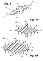
- FIG. 1 is a perspective view of one embodiment of a wound closure device in accordance with the principles of the present disclosure
- FIG. 1A is a side cross-sectional view of another embodiment of a wound closure device in accordance with the principles of the present disclosure
- FIG. 1B is a side cross-sectional view of yet another embodiment of a wound closure device in accordance with the principles of the present disclosure
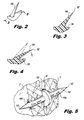
- FIG. 2 is perspective view illustrating one embodiment of a barb of the wound closure device of FIG.1 ;
- FIG. 3 is a side cross-sectional view of the barb shown in FIG. 2 , the barb being illustrated in a first position;
- FIG. 4 is a side cross-sectional view of the barb shown in FIG. 2 , the barb being illustrated in a second position;
- FIG. 5 is a perspective view illustrating the wound closure device of FIG. 1 positioned within tissue
- FIG. 6 is a perspective view of another embodiment of wound closure device in accordance with the present disclosure.
- FIG. 7 is perspective view illustrating one embodiment of a barb of the wound closure device of FIG.6 ;
- FIG. 8 is a side cross-sectional view of the barb shown in FIG. 7 , the barb being illustrated in a first position;
- FIG. 9 is a side cross-sectional view of the barb shown in FIG. 7 , the barb being illustrated in a second position;
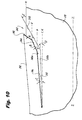
- FIG. 10 is an enlarged side view of the barb of FIG. 7 ;
- FIG. 11 is an enlarged side view of another embodiment of a barb of the wound closure device of FIG.6 ;
- FIG. 12 is an enlarged side view of yet another embodiment of a barb of the wound closure device of FIG.6 .
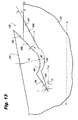
- FIG. 13 is an enlarged side view of another embodiment of a barb of the wound closure device of FIG.6 ;
- FIG. 14 is an enlarged side view of yet another embodiment of a barb of the wound closure device of FIG.6 .
- proximal refers to the end of the apparatus that is closer to the user and the term “distal” refers to the end of the apparatus that is farther from the user.
- distal refers to the end of the apparatus that is farther from the user.
- Wound closure device 100 includes an elongated body 110, a depth stop 120, and one or more barbs 130.
- the elongated body 110 defines a longitudinal axis "Z" and includes a pointed tip 112 on each end thereof.
- the depth stop 120 is positioned on the elongated body 110 to limit the insertion depth of at least a portion of the elongated body 110 within tissue "T.”
- the depth stop 120 further separates the opposing sections of the elongated body 110.
- the one or more barbs 130 extend from the elongated body 110.
- the elongated body 110 may include a plurality of barbs 130 formed along at least a portion of a length thereof.
- One or more barbs 130 may be formed projecting from the elongated body 110 toward one end, while one or more barbs 130 may be projecting from the elongated body 110 toward the other end so as to form a bi-directional wound closure device 100 as generally illustrated in FIG. 1 .
- the tips of the one or more barbs are oriented towards depth stop 120.
- a plurality of axially spaced barbs may be formed in the same or random configuration and/or at different angles in relation to each other.
- the wound closure device 100 may include a plurality of barbs spaced at the same and/or different lengths and/or in specified and/or random patterns according to the type of tissue being manipulated and/or procedure performed (not shown).
- the elongated body 110, the depth stop 120, and/or the one or more barbs 130 may include absorbable materials, non-absorbable materials, and combinations thereof.
- FIGS. 1A and 1B show alternate embodiments of wound closure devices in which the diameters of the elongate bodies thereof may have fluctuating diameters.
- FIG. 1A illustrates a wound closure device 100b having an elongate body 102 that has a diameter which changes along the length of the longitudinal axis "z.” More specifically, the diameter gradually increases toward the middle, or depth stop, and then gradually decrease toward both ends thereof.
- FIG. 1B illustrates a wound closure device 100c that has an elongate body 104 that has a diameter which changes along the length of the longitudinal axis "z," more specifically, the diameter comprises a series of steps 106 therealong the longitudinal axis. The steps 106 comprise smaller diameters near the ends thereof and larger diameters near the middle, or depth stop.
- the elongated body 110 has first and second ends 110a, 110b.
- the ends 110a, 110b are configured and dimensioned for insertion within tissue "T” on opposed sides of a wound "W.”
- the one or more barbs 130 may be movable between first and second positions.
- the one or more barbs 130 include a distal tip 132. In one position, the distal tip 132 is in close cooperative alignment with the elongated body 110 ( FIG. 4 ). In another position, the distal tip 132 is radially offset from the elongated body 110 ( FIG. 3 ).
- Wound closure device 200 is similar to wound closure device 100 and will be described herein to the extent necessary to describe the differences in construction and operability thereof.
- Wound closure device 200 includes an elongated body 210, a depth stop 120, and one or more barbs 230.
- the elongated body 210 defines a longitudinal axis "Z" and includes a pointed tip 212 on each end thereof.
- Each of the one or more barbs 230 defines an inner surface 240.
- the inner surface 240 of the one or more barbs 230 has top and bottom sections 240a, 240b.
- the top section 240a includes a first portion 242, a second portion 244, and a third portion 246.
- the bottom section 240b includes a first portion 243 and a second portion 245.
- the top and bottom sections 240a, 240b may include complementary mating surfaces.
- the first portion 242 may be disposed at a first orientation relative to the longitudinal axis "Z" of the elongated body 210.
- the second portion 244 may be disposed at a second orientation relative to the longitudinal axis "Z.”
- the third portion 246 may be disposed at a third orientation relative to the longitudinal axis "Z.”
- the first portion 243 may be disposed at a first orientation relative to the longitudinal axis "Z” and the second portion 245 may be disposed at a second orientation relative to the longitudinal axis "Z.”
- One or more of the orientations may be similar, different, and/or identical.
- top section 240a includes only a first and second portion, 242, and 244 respectively.
- first, second and/or third portions 242, 244, 246 may be at first, second, and third angles relative to the longitudinal axis "Z" of the elongated body 210.
- first and second portions 243, 245 may be at fourth and fifth angles relative to the longitudinal axis "Z" of the elongated body 210.
- these angles illustrated by characters A-E relative to respective longitudinal axes a-e may each be about 0 degrees to about 90 degrees (longitudinal axes a-e are parallel to the longitudinal axis "Z" of the elongated body 210).
- one or more of the angles are about 30 degrees to about 40 degrees.
- one or more of the angles are about 2 degrees to about 10 degrees.
- first, second, and third portions 242, 244, 246 may be substantially linear and/or non-linear. Similarly, one or both of the first and second portions 243, 245 may be substantially linear and/or non-linear. In embodiments, one or more of the first, second, and third portions 242, 244, 246 may be arcuate. Similarly, one or both of the first and second portions 243, 245 may be arcuate. In embodiments, one or more of the first, second, and third portions 242, 244, 246 may include one or more inflection points and/or one or more concave and/or convex portions. Similarly, one or both of the first and second portions 243, 245 may include one or more inflection points and/or one or more concave and/or convex portions.
- Barb 330 is similar to barb 230 and will be described herein to the extent necessary to describe the differences in construction and operability thereof.
- Barb 330 defines an inner surface 340.
- the inner surface 340 of barb 330 has top and bottom sections 340a, 340b.
- the top section 340a includes a first portion 342, a second portion 344, and a third portion 346.
- the bottom section 340b includes a first portion 343, a second portion 345, and a third portion 347.
- the top and bottom sections 340a, 340b may include complementary mating surfaces.
- the first portion 342 may be disposed at a first orientation relative to the longitudinal axis "Z" of the elongated body 210.
- the second portion 344 may be disposed at a second orientation relative to the longitudinal axis "Z.”
- the third portion 346 may be disposed at a third orientation relative to the longitudinal axis "Z.”
- the first portion 343 may be disposed at a first orientation relative to the longitudinal axis "Z.”
- the second portion 345 may be disposed at a second orientation relative to the longitudinal axis "Z.”
- the third portion 347 may be disposed at a third orientation relative to the longitudinal axis "Z.”
- One or more of the orientations may be similar, different, and/or identical.
- first, second and/or third portions 342, 344, 346 may be at first, second, and third angles relative to respective longitudinal axes of the elongated body 210.
- first, second, and third portions 343, 345, 347 may be at fourth, fifth, and sixth angles relative to the longitudinal axis "Z" of the elongated body 210.
- these angles illustrated by characters F-K relative to respective longitudinal axes f-k may each be about 0 degrees to about 90 degrees (longitudinal axes f-k are parallel to the longitudinal axis "Z" of the elongated body 210).
- one or more of the angles are about 30 degrees to about 50 degrees.
- one or more of the angles are about 2 degrees to about 25 degrees.
- first, second, and third portions 342, 344, 346 may be substantially linear and/or non-linear. Similarly, one or more of the first, second, and third portions 343, 345, 347 may be substantially linear and/or non-linear. In embodiments, one or more of the first, second, and third portions 342, 344, 346 may be arcuate. Similarly, one or more of the first, second, and third portions 343, 345, 347 may be arcuate. In embodiments, one or more of the first, second, and third portions 342, 344, 346 may include one or more inflection points and/or one or more concave and/or convex portions. Similarly, one or more of the first, second, and third portions 343, 345, 347 may include one or more inflection points and/or one or more concave and/or convex portions.
- Barb 430 is similar to barb 230 and will be described herein to the extent necessary to describe the differences in construction and operability thereof.
- Barb 430 defines an inner surface 440.
- the inner surface 440 of barb 430 has top and bottom sections 440a, 440b.
- the top section 440a includes a first portion 442, a second portion 444, and a third portion 446.
- the bottom section 440b includes a first portion 443, a second portion 445, and a third portion 447.
- the top and bottom sections 440a, 440b may include complementary mating surfaces.
- the first portion 442 may be disposed at a first orientation relative to the longitudinal axis "Z" of the elongated body 210.
- the second portion 444 may be disposed at a second orientation relative to the longitudinal axis "Z.”
- the third portion 446 may be disposed at a third orientation relative to the longitudinal axis "Z.”
- the first portion 443 may be disposed at a first orientation relative to the longitudinal axis "Z.”
- the second portion 445 may be disposed at a second orientation relative to the longitudinal axis "Z.”
- the third portion 447 may be disposed at a third orientation relative to the longitudinal axis "Z.”
- One or more of the orientations may be similar, different, and/or identical.
- first, second and/or third portions 442, 444, 446 may be at first, second, and third angles relative to respective longitudinal axes of the elongated body 410.
- first, second, and third portions 443, 445, 447 may be at fourth, fifth, and sixth angles relative to the longitudinal axis "Z" of the elongated body 210.
- these angles illustrated by characters L-Q relative to respective longitudinal axes I-q, may each be about 0 degrees to about 90 degrees (longitudinal axes I-q are parallel to the longitudinal axis "Z" of the elongated body 210).
- one or more of the angles are about 30 degrees to about 50 degrees.
- one or more of the angles are about 2 degrees to about 25 degrees.
- first, second, and third portions 442, 444, 446 may be substantially linear and/or non-linear. Similarly, one or more of the first, second, and third portions 443, 445, 447 may be substantially linear and/or non-linear. In embodiments, one or more of the first, second, and third portions 442, 444, 446 may be arcuate. Similarly, one or more of the first, second, and third portions 443, 445, 447 may be arcuate. In embodiments, one or more of the first, second, and third portions 442, 444, 446 may include one or more inflection points and/or one or more concave and/or convex portions. Similarly, one or more of the first, second, and third portions 443, 445, 447 may include one or more inflection points and/or one or more concave and/or convex portions.
- Barb 530 is similar to barb 230 and will be described herein to the extent necessary to describe the differences in construction and operability thereof.
- Barb 530 defines an inner surface 540.
- the inner surface 540 of the barb 530 has top and bottom sections 540a, 540b.
- the top section 540a includes a first portion 542, a second portion 544, and a third portion 546.
- the bottom section 540b includes a first portion 543, a second portion 545, and a third portion 547.
- the top and bottom sections 540a, 540b may include complementary mating surfaces.
- the first portion 542 may be disposed at a first orientation relative to the longitudinal axis "Z" of the elongated body 210.
- the second portion 544 may be disposed at a second orientation relative to the longitudinal axis "Z.”
- the third portion 546 may be disposed at a third orientation relative to the longitudinal axis "Z.”
- the first portion 543 may be disposed at a first orientation relative to the longitudinal axis "Z.”
- the second portion 545 may be disposed at a second orientation relative to the longitudinal axis "Z.”
- the third portion 547 may be disposed at a third orientation relative to the longitudinal axis "Z.”
- One or more of the orientations may be similar, different, and/or identical.
- first, second and/or third portions 542, 544, 546 may be at first, second, and third angles relative to respective longitudinal axes of the elongated body 510.
- first, second, and third portions 543, 545, 547 may be at fourth, fifth, and sixth angles relative to the longitudinal axis "Z" of the elongated body 210.
- characters S-V illustrate one or more of these angles relative to respective longitudinal axes s-v. Each angle may be about 0 degrees to about 90 degrees (longitudinal axes s-v are parallel to the longitudinal axis "Z" of the elongated body 210). In embodiments, one or more of the angles are about 30 degrees to about 50 degrees. In embodiments, one or more of the angles are about 2 degrees to about 25 degrees.
- first, second, and third portions 542, 544, 546 may be substantially linear and/or non-linear.
- one or more of the first, second, and third portions 543, 545, 547 may be substantially linear and/or non-linear.
- One or more of the first, second, and third portions 542, 544, 546 may be arcuate.
- one or more of the first, second, and third portions 543, 545, 547 may be arcuate.
- second portion 544 and second portion 545 have radii of curvature illustrated by respective first and second radii designated R1 and R2.
- one or more of the first, second, and third portions 542, 544, 546 may include one or more inflection points and/or one or more concave and/or convex portions.
- one or more of the first, second, and third portions 543, 545, 547 may include one or more inflection points and/or one or more concave and/or convex portions.
- Barb 630 is similar to barb 230 and will be described herein to the extent necessary to describe the differences in construction and operability thereof.
- Barb 630 defines an inner surface 640.
- the inner surface 640 of barb 630 has top and bottom sections 640a, 640b.
- the top and bottom sections 640a, 640b may include complementary mating surfaces.
- the top and bottom sections 640a, 640b may be substantially linear and/or non-linear. As illustrated in FIGS. 14 , one or both of the top and bottom sections 640a, 640b may include one or more arcuate portions such as arcuate portions 642, 643, 644, 645, 646, 647, 648, and 649 having radii of curvature R3, R4, R5, R6, R7, R8, R9, and R10, respectively. One or more of the arcuate portions 542, 544, 546 may include one or more inflection points and/or one or more concave and/or convex portions.
- the barbs may be arranged on a first portion of a length of the elongated body to allow movement of a first end of the wound closure device through tissue in one direction, while barbs on a second portion of the length of the elongated body may be arranged to allow movement of the second end of the wound closure device in an opposite direction.
- the barbs can be arranged in any suitable pattern, for example, helical, linear, or randomly spaced.
- the pattern may be symmetrical or asymmetrical.
- the number, configuration, spacing and surface area of the barbs can vary depending upon the tissue in which the wound closure device is used, as well as the composition and geometry of the material utilized to form the wound closure device. Additionally, the proportions of the barbs may remain relatively constant while the overall length of the barbs and the spacing of the barbs may be determined by the tissue being connected. For example, if the wound closure device is to be used to connect the edges of a wound in skin or tendon, the barbs may be made relatively short and more rigid to facilitate entry into this rather firm tissue. Alternatively, if the wound closure device is intended for use in fatty tissue, which is relatively soft, the barbs may be made longer and spaced further apart to increase the ability of the wound closure device to grip the soft tissue.
- the surface area of the barbs can also vary.
- fuller-tipped barbs can be made of varying sizes designed for specific surgical applications. For joining fat and relatively soft tissues, larger barbs may be desired, whereas smaller barbs may be more suitable for collagen-dense tissues.
- a combination of large and small barbs within the same structure may be beneficial, for example when a wound closure device is used in tissue repair with differing layer structures.
- a single directional wound closure device may have both large and small barbs; in other embodiments a bi-directional wound closure device may have both large and small barbs.
- barbs of the present disclosure may have various stiffness and/or flexibility.
- some barbs may be rigid while others are flexible.
- the geometry may be varied such as altering the thickness and/or depth and/or shape of some of the barbs.
- the barbs may have various surface treatments and/or include additional and/or limited amounts of cross-linking in order to alter the flexibility and/or rigidity of one or more of the presently disclosed barbs.
- some barbs comprise a surface treatment, such as a coating to increase the rigidity.
- Barb flexibility and rigidity can also be controlled by controlled parameters such as barb thickness and length. Barbs which are thicker and/or shorter are more rigid compared to barbs which are thinner and/or longer.
- the wound closure devices in accordance with the present disclosure may be formed of absorbable materials, non-absorbable materials, and combinations thereof. More particularly, the wound closure devices may be formed of an absorbable material selected from the group consisting of polyesters, polyorthoesters, polymer drugs, polydroxybutyrates, dioxanones, lactones, proteins, cat gut, collagens, carbonates, homopolymers thereof, copolymers thereof, and combinations thereof.
- suitable absorbable materials which may be utilized to form the wound closure device include natural collagenous materials or synthetic resins including those derived from alkylene carbonates such as trimethylene carbonate, tetramethylene carbonate, and the like, caprolactone, glycolic acid, lactic acid, glycolide, lactide, homopolymers thereof, copolymers thereof, and combinations thereof.
- glycolide and lactide based polyesters, especially copolymers of glycolide and lactide may be utilized to form the wound closure device of the present disclosure.
- Barbed wound closure devices fabricated from an absorbable material in accordance with the present disclosure maintain their structural integrity after implantation (e.g., about 80% of original strength) for a period of time, depending on the various processing parameter and the particular copolymer used.
- Such characteristics include, for example, the components of the copolymer, including both the monomers utilized to form the copolymer and any additives thereto, as well as the processing conditions (e.g., rate of copolymerization reaction, temperature for reaction, pressure, etc.), and any further treatment of the resulting copolymers, i.e., coating, sterilization, etc.
- suitable non-absorbable materials which may be utilized to form the wound closure device include polyolefins, such as polyethylene, polypropylene, copolymers of polyethylene and polypropylene, and blends of polyethylene and polypropylene; polyamides (such as nylon); polyamines, polyimines, polyesters such as polyethylene terephthalate; fluoropolymers such as polytetrafluoroethylene; polyetheresters such as polybutesters; polytetramethylene ether glycol; 1,4-butanediol; polyurethanes; and combinations thereof.
- polyolefins such as polyethylene, polypropylene, copolymers of polyethylene and polypropylene, and blends of polyethylene and polypropylene
- polyamides such as nylon
- polyamines such as polyimines
- polyesters such as polyethylene terephthalate
- fluoropolymers such as polytetrafluoroethylene
- polyetheresters such as polybutesters
- non-absorbable materials may include silk, cotton, linen, carbon fibers, and the like.
- the polypropylene can be isotactic polypropylene or a mixture of isotactic and syndiotactic or atactic polypropylene.
- the wound closure devices in accordance with the present disclosure may be coated or impregnated with one or more synthetic or natural polymers e.g., bioactive agents which accelerate or beneficially modify the healing process when the wound closure device is applied to a wound or surgical site.
- a bioactive agent may be solely disposed within the angle between the barb and the elongate body. Placement of a bioactive agent in the angle formed between the barbs and the elongate body surface places the bioactive agent at precisely defined locations within a tissue wound closure, thereby providing a unique controlled and sustained release dosage form (as opposed to coating entire wound closure device with a bioactive agent)
- the coating may be formed from absorbable polymers selected from the group consisting of lactones, carbonates, polyorthoesters, hydroxyalkoanates, hydroxybutyrates, bioactive agents, polyanhydrides, silicone, vinyl polymers, high molecular weight waxes and oils, natural polymers, proteins, polysaccharides, suspendable particulates, dispersible particulates, microspheres, nanospheres, rods, homopolymers thereof, copolymers thereof, and combinations thereof.
- absorbable polymers selected from the group consisting of lactones, carbonates, polyorthoesters, hydroxyalkoanates, hydroxybutyrates, bioactive agents, polyanhydrides, silicone, vinyl polymers, high molecular weight waxes and oils, natural polymers, proteins, polysaccharides, suspendable particulates, dispersible particulates, microspheres, nanospheres, rods, homopolymers thereof, copolymers thereof, and combinations thereof.
- Suitable bioactive agents that may be impregnated with or coated on the presently disclosed wound closure devices include, for example, biocidal agents, antimicrobial agents, antibiotics, anti-proliferatives, medicants, growth factors, anti-clotting agents, clotting agents, analgesics, anesthetics, anti-inflammatory agents, wound repair agents and the like, chemotherapeutics, biologics, protein therapeutics, monoclonal or polyclonal antibodies, DNA, RNA, peptides, polysaccharides, lectins, lipids, probiotics, diagnostic agents, angiogenics, anti-angiogenic drugs, polymeric drugs, and combinations thereof.
- Bioactive agents that may be impregnated with or coated on the presently disclosed wound closure devices include substances which are beneficial to the animal and tend to promote the healing process.
- a wound closure device can be provided with a bioactive agent that will be deposited at the surgical site.
- the bioactive agent can be chosen for its antimicrobial properties, capability for promoting wound repair and/or tissue growth, or for specific indications such as thrombosis.
- antimicrobial agent includes an agent which by itself or through assisting the immune system, helps the body destroy or resist microorganisms which may be pathogenic.
- An antimicrobial agent includes antibiotics, antiseptics, quorum sensing blockers, antifungals, anti-virals, surfactants, metal ions, antimicrobial proteins and peptides, antimicrobial polysaccharides, disinfectants and combinations thereof.
- Antimicrobial agents which are slowly released into the tissue can be applied in this manner to aid in combating clinical and sub-clinical infections in a surgical or trauma wound site.
- suitable antimicrobial agents may be soluble in one or more solvents.
- the following anti-microbial agents may be used alone or in combination with other bioactive agents described herein: an anthracycline, doxorubicin, mitoxantrone, a fluoropyrimidine, 5-fluorouracil (5-FU), a folic acid antagonist, methotrexate, mitoxantrone, quorum sensing blocker, brominated or halogenated furanones, a podophylotoxin, etoposide, camptothecin, a hydroxyurea, a platinum complex, cisplatin, doxycycline, metronidazole, trimethoprim-sulfamethoxazole, rifamycins like rifampin, a fourth generation penicillin (e.g., a ureidopenicillin a carboxypenicillin, meziocillin, piperacillin, carbenicillin, and ticarcillin, and an analogue or derivative thereof), a first generation ce
- sulfamethoxazole trimethoprim, including cefixime, spectinomycin, tetracycline, nitrofurantoin, polymyxin B, and neomycin sulfate), beta-lactam inhibitors like sulbactam, chloramphenicol, glycopeptides like vancomycin, mupirocin, polyenes like amphotericin B, azoles like fluconazole, and other known antimicrobial agent known in the art.
- chemotherapeutics which may be utilized include one or more of the following: doxorubicin (Dox), paclitaxel (PTX), or camptothecin (CPT), polyglutamate-PTX (CT-2103 or Xyotax), N-(2-hydroxypropyl)methacrylamide (HPMA) copolymer, anthracycline, mitoxantrone, letrozole, anastrozole, epidermal growth factor receptor inhibitors, tyrosine kinase inhibitors,modulators of apoptosis, anthracycline antibiotics such as daunorubicin and doxorubicin, alkylating agents such as cyclophosphamide and melphalan, antimetabolites such as methotrexate and 5-fluorouracil, poly(ethylene glycol) (PEG), poly(glutamic acid) (PGA), polysaccharides, monoclonal antibody and polymer-drug conjugates thereof, copolymers thereof and
- the clotting agents include one or more of the following: a fibrosing agent that promotes cell regeneration, a fibrosing agent that promotes angiogenesis, a fibrosing agent that promotes fibroblast migration, a fibrosing agent that promotes fibroblast proliferation, a fibrosing agent that promotes deposition of extracellular matrix, a fibrosing agent that promotes tissue remodeling, a fibrosing agent that is a diverticular wall irritant, silk (such as silkworm silk, spider silk, recombinant silk, raw silk, hydrolyzed silk, acid-treated silk, and acylated silk), talc, chitosan, bleomycin or an analogue or derivative thereof, connective tissue growth factor (CTGF), metallic beryllium or an oxide thereof, copper, saracin, silica, crystalline silicates, quartz dust, talcum powder, ethanol, a component of extracellular matrix, oxidized cellulose, polysaccharides, collagen, fibrin,
- a wide variety of anti-angiogenic factors may be readily impregnated with or coated on the presently disclosed wound closure devices.
- Representative examples include Anti-Invasive Factor; retinoic acid and derivatives thereof; paclitaxel a highly derivatized diterpenoid; Suramin; Tissue Inhibitor of Metalloproteinase-1; Tissue Inhibitor of Metalloproteinase-2; Plasminogen Activator Inhibitor-1; Plasminogen Activator Inhibitor-2; various forms of the lighter “d group” transition metals such as, for example, vanadium, molybdenum, tungsten, titanium, niobium, and tantalum species and complexes thereof; Platelet Factor 4; Protamine Sulphate (Clupeine); Sulphated Chitin Derivatives (prepared from queen crab shells); Sulphated Polysaccharide Peptidoglycan Complex (SP-PG) (the function of this compound may be enhanced by the presence of steroids
- polymeric drugs may be impregnated with or coated on the presently disclosed wound closure devices.
- Representative examples include steroidal anti-inflammatory agents, non-steroidal anti-inflammatory agents, and combinations thereof.
- examples of the non-steroidal anti-inflammatory agent which may be used with the present disclosure are aspirin, indomethacin, ibuprofen, phenylbutazone, diflusinal, and combinations thereof.
- glucocorticoids such as cortisone and hydrocortisone, betamethasone, dexamethasone, fluprednisolone, prednisone, methylprednisolone, prednisolone, triamcinolone, paramethasone, and combinations thereof.
- bioactive agents have been provided for the purposes of illustration, it should be understood that the present disclosure is not so limited.
- certain bioactive agents are specifically referred to above, the present disclosure should be understood to include analogues, derivatives and conjugates of such agents.
- wound closure devices in accordance with this disclosure can also include, for example, biologically acceptable plasticizers, antioxidants and colorants, which can be impregnated into the barbs of the present disclosure or included in a coating thereon.
- Bioactive agents may be applied onto a barbed wound closure device of the present disclosure utilizing any method within the purview of one skilled in the art including, for example, dipping, spraying, vapor deposition, brushing, mixing, compounding and the like.
- the wound closure devices of the present disclosure may contain additives such as dyes, pigments, and colorants in order to increase the visibility of the device in the surgical field.
- additives such as dyes, pigments, and colorants in order to increase the visibility of the device in the surgical field.
- Any suitable agent such as those agents within the purview of those skilled in the art can be used in accordance with the present disclosure.
- wound closure devices of the present disclosure may be utilized in any cosmetic, endoscopic or laparoscopic methods.
Landscapes
- Health & Medical Sciences (AREA)
- Life Sciences & Earth Sciences (AREA)
- Surgery (AREA)
- Heart & Thoracic Surgery (AREA)
- Engineering & Computer Science (AREA)
- Biomedical Technology (AREA)
- Nuclear Medicine, Radiotherapy & Molecular Imaging (AREA)
- Medical Informatics (AREA)
- Molecular Biology (AREA)
- Animal Behavior & Ethology (AREA)
- General Health & Medical Sciences (AREA)
- Public Health (AREA)
- Veterinary Medicine (AREA)
- Surgical Instruments (AREA)
- Fencing (AREA)
Abstract
Description
- The present disclosure relates generally to incisional hernia prevention. In particular, the present disclosure relates to a medical device for closing a wound that includes one or more barbed pins.
- Today, many surgical procedures are performed through small incisions in the skin, as compared to the larger incisions typically required in traditional procedures, in an effort to reduce both trauma to the patient and recovery time. Generally, such procedures are referred to as "endoscopic", unless performed on the patient's abdomen, in which case the procedure is referred to as "laparoscopic." Throughout the present disclosure, the term "minimally invasive" should be understood to encompass both endoscopic and laparoscopic procedures. In order to complete the procedure, each incision requires closure in order to protect against hernia, adhesions, and other undesirable conditions.
- Fastening devices with medical and surgical applications have been described in the prior art. For example,
U.S. Patent Application Publication No. 2003/0032961 discloses a double-ended orthopedic tack device having body portions extending from opposing sides of a head portion. The body portions include a threaded portion extending outward from a central body portion. Each body portion may be inserted into opposing bone or tissue structure. In another example,U.S. Patent No. 6,620,178 discloses a blood vessel grafting aid for joining two blood vessels together. In one embodiment, the blood vessel grafting aid includes a shaft with a centrally positioned plate thereon and a plurality of prongs extending from the shaft to engage into the vessels. In yet another example,U.S. Patent Application Publication No. 2010/0049244 discloses a threaded tissue tack for use in approximating and securing a pair of tissue sections together. The threaded tissue tack has a central body portion and first and second screws extending from opposite ends of the central body portion. - While these previous disclosures teach medical fastening devices, some of which are particularly used for tissue approximation, a continuing need exists for a device that enables a surgeon to securely close an open wound with relative ease and with minor inconvenience.
- Accordingly, a wound closure device is provided which includes an elongated body, a depth stop, and one or more barbs. The depth stop is positioned on the elongated body to limit the insertion depth of at least a portion of the elongated body within tissue. The one or more barbs extend radially outward from the elongated body. The elongated body may include a plurality of barbs formed along at least a portion of a length thereof. One or more of the elongated body, the depth stop, and the one or more barbs comprises a material selected from the group consisting of absorbable materials, non-absorbable materials, and combinations thereof.
- The elongated body has first and second sections. The sections are configured and dimensioned for insertion within tissue on opposed sides of a wound. In embodiments, the one or more barbs include an inner surface having one or more inflection points. The inner surface may include one or more concave portions and/or one or more convex portions.
- The one or more barbs may be movable between first and second positions. The one or more barbs include a distal tip. In the first position, the distal tip is in close cooperative alignment with the elongated body. In the second position, the distal tip is radially offset from the elongated body.
- The one or more barbs define an inner surface. The inner surface includes a first portion, a second portion, and a third portion. The first portion may be disposed at a first orientation relative to a longitudinal axis of the elongated body. The second portion may be disposed at a second orientation relative to the longitudinal axis. The third portion may be disposed at a third orientation relative to the longitudinal axis. One or more of the first, second, and third portions may be substantially linear. The first, second, and third portions may be at first, second, and third angles relative to respective longitudinal axes of the elongated body. In embodiments, the second angle may be less than each of the first and third angles. The first angle may be about 0 degrees to about 90 degrees. In one embodiment, the first angle is about 30 degrees to about 50 degrees. The second angle may be about 0 degrees to about 90 degrees. In one embodiment, the second angle is about 2 degrees to about 25 degrees. The third angle is about 0 degrees to about 90 degrees. In one embodiment, the third angle is about 25 degrees to about 50 degrees.
- One or more of the first, second, and third portions may be substantially non-linear. In embodiments, one of the first, second, and third portions is arcuate. In embodiments, one of the first, second, and third portions may be substantially linear and one or more of the first, second, and third portions may be arcuate.
- According to another aspect, the wound closure device includes an elongated body and one or more barbs extending radially outward from the elongated body. The elongated body has first and second sections. The sections are configured and dimensioned for insertion within tissue on opposed sides of a wound. The one or more barbs define an inner surface having a first portion disposed at a first orientation relative to a longitudinal axis of the elongated body and a second portion disposed at a second orientation relative to the longitudinal axis.
- In yet another aspect, a wound closure device includes an elongated body and first and second barbs extending substantially radially outwardly from the elongated body. The elongated body has first and second sections that are configured and dimensioned for insertion within tissue on opposed sides of a wound. One of the first and second barbs has either more flexibility or more rigidity than the other of the first and second barbs. The first barb may be formed of a first material and the second barb may be formed of a second material different than the first material, each material having either more flexibility or more rigidity than the other of the first and second material. In one embodiment, the first and second barbs have different geometries. The first and second barbs may have different thicknesses and/or depths. One or both of the first and second barbs may have one or more surface treatments. One or both of the first and second barbs may have additional cross-linking.
- Various embodiments of the present disclosure will be described herein below with reference to the figures wherein:
-
FIG. 1 is a perspective view of one embodiment of a wound closure device in accordance with the principles of the present disclosure; -
FIG. 1A is a side cross-sectional view of another embodiment of a wound closure device in accordance with the principles of the present disclosure; -
FIG. 1B is a side cross-sectional view of yet another embodiment of a wound closure device in accordance with the principles of the present disclosure; -
FIG. 2 is perspective view illustrating one embodiment of a barb of the wound closure device ofFIG.1 ; -
FIG. 3 is a side cross-sectional view of the barb shown inFIG. 2 , the barb being illustrated in a first position; -
FIG. 4 is a side cross-sectional view of the barb shown inFIG. 2 , the barb being illustrated in a second position; -
FIG. 5 is a perspective view illustrating the wound closure device ofFIG. 1 positioned within tissue; -
FIG. 6 is a perspective view of another embodiment of wound closure device in accordance with the present disclosure; -
FIG. 7 is perspective view illustrating one embodiment of a barb of the wound closure device ofFIG.6 ; -
FIG. 8 is a side cross-sectional view of the barb shown inFIG. 7 , the barb being illustrated in a first position; -
FIG. 9 is a side cross-sectional view of the barb shown inFIG. 7 , the barb being illustrated in a second position; -
FIG. 10 is an enlarged side view of the barb ofFIG. 7 ; -
FIG. 11 is an enlarged side view of another embodiment of a barb of the wound closure device ofFIG.6 ; -
FIG. 12 is an enlarged side view of yet another embodiment of a barb of the wound closure device ofFIG.6 . -
FIG. 13 is an enlarged side view of another embodiment of a barb of the wound closure device ofFIG.6 ; and -
FIG. 14 is an enlarged side view of yet another embodiment of a barb of the wound closure device ofFIG.6 . - Particular embodiments of the present disclosure will be described herein with reference to the accompanying drawings. As shown in the drawings and as described throughout the following description, and as is traditional when referring to relative positioning on an object, the term "proximal" refers to the end of the apparatus that is closer to the user and the term "distal" refers to the end of the apparatus that is farther from the user. In the following description, well-known functions or constructions are not described in detail to avoid obscuring the present disclosure in unnecessary detail.
- Referring now to
FIG.1 , one embodiment of a wound closure device is illustrated which is generally referred to as 100.Wound closure device 100 includes anelongated body 110, adepth stop 120, and one ormore barbs 130. Theelongated body 110 defines a longitudinal axis "Z" and includes apointed tip 112 on each end thereof. As best shown inFIG. 5 , thedepth stop 120 is positioned on theelongated body 110 to limit the insertion depth of at least a portion of theelongated body 110 within tissue "T." Thedepth stop 120 further separates the opposing sections of theelongated body 110. The one ormore barbs 130 extend from theelongated body 110. Theelongated body 110 may include a plurality ofbarbs 130 formed along at least a portion of a length thereof. One ormore barbs 130 may be formed projecting from theelongated body 110 toward one end, while one ormore barbs 130 may be projecting from theelongated body 110 toward the other end so as to form a bi-directionalwound closure device 100 as generally illustrated inFIG. 1 . Generally, the tips of the one or more barbs are oriented towardsdepth stop 120. Alternatively, a plurality of axially spaced barbs may be formed in the same or random configuration and/or at different angles in relation to each other. Optionally, thewound closure device 100 may include a plurality of barbs spaced at the same and/or different lengths and/or in specified and/or random patterns according to the type of tissue being manipulated and/or procedure performed (not shown).Theelongated body 110, thedepth stop 120, and/or the one ormore barbs 130 may include absorbable materials, non-absorbable materials, and combinations thereof. - Referring now to
FIGS. 1A and 1B , show alternate embodiments of wound closure devices in which the diameters of the elongate bodies thereof may have fluctuating diameters.FIG. 1A illustrates awound closure device 100b having anelongate body 102 that has a diameter which changes along the length of the longitudinal axis "z." More specifically, the diameter gradually increases toward the middle, or depth stop, and then gradually decrease toward both ends thereof.FIG. 1B illustrates awound closure device 100c that has anelongate body 104 that has a diameter which changes along the length of the longitudinal axis "z," more specifically, the diameter comprises a series ofsteps 106 therealong the longitudinal axis. Thesteps 106 comprise smaller diameters near the ends thereof and larger diameters near the middle, or depth stop. - With continued reference to
FIGS. 1 and5 , theelongated body 110 has first andsecond ends ends - As illustrated in
FIGS. 3 and 4 , the one ormore barbs 130 may be movable between first and second positions. The one ormore barbs 130 include adistal tip 132. In one position, thedistal tip 132 is in close cooperative alignment with the elongated body 110 (FIG. 4 ). In another position, thedistal tip 132 is radially offset from the elongated body 110 (FIG. 3 ). - Referring now to
FIGS. 6-10 , another embodiment of a wound closure device is illustrated and is generally referred to as 200.Wound closure device 200 is similar to woundclosure device 100 and will be described herein to the extent necessary to describe the differences in construction and operability thereof.Wound closure device 200 includes anelongated body 210, adepth stop 120, and one ormore barbs 230. Theelongated body 210 defines a longitudinal axis "Z" and includes apointed tip 212 on each end thereof. Each of the one ormore barbs 230 defines aninner surface 240. Theinner surface 240 of the one ormore barbs 230 has top andbottom sections top section 240a includes afirst portion 242, asecond portion 244, and athird portion 246. Thebottom section 240b includes afirst portion 243 and asecond portion 245. The top andbottom sections - With regards to the
top section 240a, thefirst portion 242 may be disposed at a first orientation relative to the longitudinal axis "Z" of theelongated body 210. Thesecond portion 244 may be disposed at a second orientation relative to the longitudinal axis "Z." Thethird portion 246 may be disposed at a third orientation relative to the longitudinal axis "Z." Similarly, with regards to thebottom section 240b, thefirst portion 243 may be disposed at a first orientation relative to the longitudinal axis "Z" and thesecond portion 245 may be disposed at a second orientation relative to the longitudinal axis "Z." One or more of the orientations may be similar, different, and/or identical. In certain embodiments,top section 240a includes only a first and second portion, 242, and 244 respectively. - In this manner, the first, second and/or
third portions elongated body 210. Similarly, the first andsecond portions elongated body 210. As illustrated inFIG. 10 , these angles, illustrated by characters A-E relative to respective longitudinal axes a-e may each be about 0 degrees to about 90 degrees (longitudinal axes a-e are parallel to the longitudinal axis "Z" of the elongated body 210). In embodiments, one or more of the angles are about 30 degrees to about 40 degrees. In embodiments, one or more of the angles are about 2 degrees to about 10 degrees. - One or more of the first, second, and
third portions second portions third portions second portions third portions second portions - Referring now to
FIGS. 11 , another embodiment of a barb is generally referred to as 330.Barb 330 is similar tobarb 230 and will be described herein to the extent necessary to describe the differences in construction and operability thereof.Barb 330 defines aninner surface 340. Theinner surface 340 ofbarb 330 has top andbottom sections 340a, 340b. Thetop section 340a includes afirst portion 342, asecond portion 344, and athird portion 346. The bottom section 340b includes afirst portion 343, asecond portion 345, and athird portion 347. The top andbottom sections 340a, 340b may include complementary mating surfaces. - With regards to the
top section 340a, thefirst portion 342 may be disposed at a first orientation relative to the longitudinal axis "Z" of theelongated body 210. Thesecond portion 344 may be disposed at a second orientation relative to the longitudinal axis "Z." Thethird portion 346 may be disposed at a third orientation relative to the longitudinal axis "Z." Similarly, with regards to the bottom section 340b, thefirst portion 343 may be disposed at a first orientation relative to the longitudinal axis "Z." Thesecond portion 345 may be disposed at a second orientation relative to the longitudinal axis "Z." Thethird portion 347 may be disposed at a third orientation relative to the longitudinal axis "Z." One or more of the orientations may be similar, different, and/or identical. - In this manner, the first, second and/or
third portions elongated body 210. Similarly, the first, second, andthird portions elongated body 210. As illustrated inFIG. 11 , these angles, illustrated by characters F-K relative to respective longitudinal axes f-k may each be about 0 degrees to about 90 degrees (longitudinal axes f-k are parallel to the longitudinal axis "Z" of the elongated body 210). In embodiments, one or more of the angles are about 30 degrees to about 50 degrees. In embodiments, one or more of the angles are about 2 degrees to about 25 degrees. - One or more of the first, second, and
third portions third portions third portions third portions third portions third portions - Referring now to
FIGS. 12 , another embodiment of a barb is generally referred to as 430.Barb 430 is similar tobarb 230 and will be described herein to the extent necessary to describe the differences in construction and operability thereof.Barb 430 defines aninner surface 440. Theinner surface 440 ofbarb 430 has top andbottom sections 440a, 440b. Thetop section 440a includes afirst portion 442, asecond portion 444, and athird portion 446. The bottom section 440b includes afirst portion 443, asecond portion 445, and athird portion 447. The top andbottom sections 440a, 440b may include complementary mating surfaces. - With regards to the
top section 440a, thefirst portion 442 may be disposed at a first orientation relative to the longitudinal axis "Z" of theelongated body 210. Thesecond portion 444 may be disposed at a second orientation relative to the longitudinal axis "Z." Thethird portion 446 may be disposed at a third orientation relative to the longitudinal axis "Z." Similarly, with regards to the bottom section 440b, thefirst portion 443 may be disposed at a first orientation relative to the longitudinal axis "Z." Thesecond portion 445 may be disposed at a second orientation relative to the longitudinal axis "Z." Thethird portion 447 may be disposed at a third orientation relative to the longitudinal axis "Z." One or more of the orientations may be similar, different, and/or identical. - In this manner, the first, second and/or
third portions elongated body 410. Similarly, the first, second, andthird portions elongated body 210. As illustrated inFIG. 12 , these angles, illustrated by characters L-Q relative to respective longitudinal axes I-q, may each be about 0 degrees to about 90 degrees (longitudinal axes I-q are parallel to the longitudinal axis "Z" of the elongated body 210). In embodiments, one or more of the angles are about 30 degrees to about 50 degrees. In embodiments, one or more of the angles are about 2 degrees to about 25 degrees. - One or more of the first, second, and
third portions third portions third portions third portions third portions third portions - Referring now to
FIGS. 13 , another embodiment of a barb is generally referred to as 530.Barb 530 is similar tobarb 230 and will be described herein to the extent necessary to describe the differences in construction and operability thereof.Barb 530 defines aninner surface 540. Theinner surface 540 of thebarb 530 has top andbottom sections 540a, 540b. Thetop section 540a includes afirst portion 542, asecond portion 544, and athird portion 546. The bottom section 540b includes afirst portion 543, asecond portion 545, and athird portion 547. The top andbottom sections 540a, 540b may include complementary mating surfaces. - With regards to the
top section 540a, thefirst portion 542 may be disposed at a first orientation relative to the longitudinal axis "Z" of theelongated body 210. Thesecond portion 544 may be disposed at a second orientation relative to the longitudinal axis "Z." Thethird portion 546 may be disposed at a third orientation relative to the longitudinal axis "Z." Similarly, with regards to the bottom section 540b, thefirst portion 543 may be disposed at a first orientation relative to the longitudinal axis "Z." Thesecond portion 545 may be disposed at a second orientation relative to the longitudinal axis "Z." Thethird portion 547 may be disposed at a third orientation relative to the longitudinal axis "Z." One or more of the orientations may be similar, different, and/or identical. - In this manner, the first, second and/or
third portions elongated body 510. Similarly, the first, second, andthird portions elongated body 210. As illustrated inFIG. 13 , characters S-V illustrate one or more of these angles relative to respective longitudinal axes s-v. Each angle may be about 0 degrees to about 90 degrees (longitudinal axes s-v are parallel to the longitudinal axis "Z" of the elongated body 210). In embodiments, one or more of the angles are about 30 degrees to about 50 degrees. In embodiments, one or more of the angles are about 2 degrees to about 25 degrees. - One or more of the first, second, and
third portions third portions third portions third portions second portion 544 andsecond portion 545 have radii of curvature illustrated by respective first and second radii designated R1 and R2. In embodiments, one or more of the first, second, andthird portions third portions - Referring now to
FIGS. 14 , another embodiment of a barb is generally referred to as 630.Barb 630 is similar tobarb 230 and will be described herein to the extent necessary to describe the differences in construction and operability thereof.Barb 630 defines aninner surface 640. Theinner surface 640 ofbarb 630 has top andbottom sections 640a, 640b. The top andbottom sections 640a, 640b may include complementary mating surfaces. - The top and
bottom sections 640a, 640b may be substantially linear and/or non-linear. As illustrated inFIGS. 14 , one or both of the top andbottom sections 640a, 640b may include one or more arcuate portions such asarcuate portions arcuate portions - In embodiments, the barbs may be arranged on a first portion of a length of the elongated body to allow movement of a first end of the wound closure device through tissue in one direction, while barbs on a second portion of the length of the elongated body may be arranged to allow movement of the second end of the wound closure device in an opposite direction.
- The barbs can be arranged in any suitable pattern, for example, helical, linear, or randomly spaced. The pattern may be symmetrical or asymmetrical. The number, configuration, spacing and surface area of the barbs can vary depending upon the tissue in which the wound closure device is used, as well as the composition and geometry of the material utilized to form the wound closure device. Additionally, the proportions of the barbs may remain relatively constant while the overall length of the barbs and the spacing of the barbs may be determined by the tissue being connected. For example, if the wound closure device is to be used to connect the edges of a wound in skin or tendon, the barbs may be made relatively short and more rigid to facilitate entry into this rather firm tissue. Alternatively, if the wound closure device is intended for use in fatty tissue, which is relatively soft, the barbs may be made longer and spaced further apart to increase the ability of the wound closure device to grip the soft tissue.
- The surface area of the barbs can also vary. For example, fuller-tipped barbs can be made of varying sizes designed for specific surgical applications. For joining fat and relatively soft tissues, larger barbs may be desired, whereas smaller barbs may be more suitable for collagen-dense tissues. In some embodiments, a combination of large and small barbs within the same structure may be beneficial, for example when a wound closure device is used in tissue repair with differing layer structures. In particular embodiments, a single directional wound closure device may have both large and small barbs; in other embodiments a bi-directional wound closure device may have both large and small barbs.
- In addition, barbs of the present disclosure may have various stiffness and/or flexibility. For example, some barbs may be rigid while others are flexible. In this respect, the geometry may be varied such as altering the thickness and/or depth and/or shape of some of the barbs. Furthermore, the barbs may have various surface treatments and/or include additional and/or limited amounts of cross-linking in order to alter the flexibility and/or rigidity of one or more of the presently disclosed barbs. In alternate embodiments, some barbs comprise a surface treatment, such as a coating to increase the rigidity. Barb flexibility and rigidity can also be controlled by controlled parameters such as barb thickness and length. Barbs which are thicker and/or shorter are more rigid compared to barbs which are thinner and/or longer.
- The wound closure devices in accordance with the present disclosure may be formed of absorbable materials, non-absorbable materials, and combinations thereof. More particularly, the wound closure devices may be formed of an absorbable material selected from the group consisting of polyesters, polyorthoesters, polymer drugs, polydroxybutyrates, dioxanones, lactones, proteins, cat gut, collagens, carbonates, homopolymers thereof, copolymers thereof, and combinations thereof. In other embodiments, suitable absorbable materials which may be utilized to form the wound closure device include natural collagenous materials or synthetic resins including those derived from alkylene carbonates such as trimethylene carbonate, tetramethylene carbonate, and the like, caprolactone, glycolic acid, lactic acid, glycolide, lactide, homopolymers thereof, copolymers thereof, and combinations thereof. In some embodiments, glycolide and lactide based polyesters, especially copolymers of glycolide and lactide, may be utilized to form the wound closure device of the present disclosure.
- Barbed wound closure devices fabricated from an absorbable material in accordance with the present disclosure maintain their structural integrity after implantation (e.g., about 80% of original strength) for a period of time, depending on the various processing parameter and the particular copolymer used. Such characteristics include, for example, the components of the copolymer, including both the monomers utilized to form the copolymer and any additives thereto, as well as the processing conditions (e.g., rate of copolymerization reaction, temperature for reaction, pressure, etc.), and any further treatment of the resulting copolymers, i.e., coating, sterilization, etc.
- For non-absorbable barbed wound closure devices constructed in accordance with the present disclosure, suitable non-absorbable materials which may be utilized to form the wound closure device include polyolefins, such as polyethylene, polypropylene, copolymers of polyethylene and polypropylene, and blends of polyethylene and polypropylene; polyamides (such as nylon); polyamines, polyimines, polyesters such as polyethylene terephthalate; fluoropolymers such as polytetrafluoroethylene; polyetheresters such as polybutesters; polytetramethylene ether glycol; 1,4-butanediol; polyurethanes; and combinations thereof. In other embodiments, non-absorbable materials may include silk, cotton, linen, carbon fibers, and the like. The polypropylene can be isotactic polypropylene or a mixture of isotactic and syndiotactic or atactic polypropylene.
- The wound closure devices in accordance with the present disclosure may be coated or impregnated with one or more synthetic or natural polymers e.g., bioactive agents which accelerate or beneficially modify the healing process when the wound closure device is applied to a wound or surgical site. In particular embodiments, a bioactive agent may be solely disposed within the angle between the barb and the elongate body. Placement of a bioactive agent in the angle formed between the barbs and the elongate body surface places the bioactive agent at precisely defined locations within a tissue wound closure, thereby providing a unique controlled and sustained release dosage form (as opposed to coating entire wound closure device with a bioactive agent)
- In certain embodiments, the coating may be formed from absorbable polymers selected from the group consisting of lactones, carbonates, polyorthoesters, hydroxyalkoanates, hydroxybutyrates, bioactive agents, polyanhydrides, silicone, vinyl polymers, high molecular weight waxes and oils, natural polymers, proteins, polysaccharides, suspendable particulates, dispersible particulates, microspheres, nanospheres, rods, homopolymers thereof, copolymers thereof, and combinations thereof.
- Suitable bioactive agents that may be impregnated with or coated on the presently disclosed wound closure devices include, for example, biocidal agents, antimicrobial agents, antibiotics, anti-proliferatives, medicants, growth factors, anti-clotting agents, clotting agents, analgesics, anesthetics, anti-inflammatory agents, wound repair agents and the like, chemotherapeutics, biologics, protein therapeutics, monoclonal or polyclonal antibodies, DNA, RNA, peptides, polysaccharides, lectins, lipids, probiotics, diagnostic agents, angiogenics, anti-angiogenic drugs, polymeric drugs, and combinations thereof.
- Bioactive agents that may be impregnated with or coated on the presently disclosed wound closure devices include substances which are beneficial to the animal and tend to promote the healing process. For example, a wound closure device can be provided with a bioactive agent that will be deposited at the surgical site. The bioactive agent can be chosen for its antimicrobial properties, capability for promoting wound repair and/or tissue growth, or for specific indications such as thrombosis.
- The term "antimicrobial agent" as used herein includes an agent which by itself or through assisting the immune system, helps the body destroy or resist microorganisms which may be pathogenic. An antimicrobial agent includes antibiotics, antiseptics, quorum sensing blockers, antifungals, anti-virals, surfactants, metal ions, antimicrobial proteins and peptides, antimicrobial polysaccharides, disinfectants and combinations thereof. Antimicrobial agents which are slowly released into the tissue can be applied in this manner to aid in combating clinical and sub-clinical infections in a surgical or trauma wound site. In embodiments, suitable antimicrobial agents may be soluble in one or more solvents.
- In embodiments, the following anti-microbial agents may be used alone or in combination with other bioactive agents described herein: an anthracycline, doxorubicin, mitoxantrone, a fluoropyrimidine, 5-fluorouracil (5-FU), a folic acid antagonist, methotrexate, mitoxantrone, quorum sensing blocker, brominated or halogenated furanones, a podophylotoxin, etoposide, camptothecin, a hydroxyurea, a platinum complex, cisplatin, doxycycline, metronidazole, trimethoprim-sulfamethoxazole, rifamycins like rifampin, a fourth generation penicillin (e.g., a ureidopenicillin a carboxypenicillin, meziocillin, piperacillin, carbenicillin, and ticarcillin, and an analogue or derivative thereof), a first generation cephalosporin (e.g., cephazolin sodium, cephalexin, cefazolin, cephapirin, and cephalothin), a carboxypenicillin (e.g., ticarcillin), a second generation cephalosporin (e.g., cefuroxime, cefotetan, and cefoxitin), a third generation cephalosporin (e.g., naxcel, cefdinir, cefoperazone, ceftazidime, ceftriaxone, and cefotaxime), polyvinyl pyrrolidone (PVP), a fourth generation cephalosporin (e.g., cefepime), a monobactam (e.g., aztreonam), a carbapenem (e.g., imipenem, ertapenem and meropenem), an aminoglycoside (e.g., streptomycin, gentamicin, tobramycin, and amikacin), an MSL group member (e.g., a macrolide, a long acting macrolide, a lincosamide, a streptogramin, Erythromycin, Azithromycin, Clindamycin, Syneroid, clarithromycin, and kanamycin sulfate), tetracyclines like minocycline, fusidic acid, trimethoprim, metronidazole; a quinolone (e.g., ciprofloxacin, ofloxacin, gatifloxacin, moxifloxacin, levofloxacin, and trovafloxacin), a DNA synthesis inhibitor (e.g., metronidazole), a sulfonamide (e.g. sulfamethoxazole, trimethoprim, including cefixime, spectinomycin, tetracycline, nitrofurantoin, polymyxin B, and neomycin sulfate), beta-lactam inhibitors like sulbactam, chloramphenicol, glycopeptides like vancomycin, mupirocin, polyenes like amphotericin B, azoles like fluconazole, and other known antimicrobial agent known in the art.
- Examples of chemotherapeutics which may be utilized include one or more of the following: doxorubicin (Dox), paclitaxel (PTX), or camptothecin (CPT), polyglutamate-PTX (CT-2103 or Xyotax), N-(2-hydroxypropyl)methacrylamide (HPMA) copolymer, anthracycline, mitoxantrone, letrozole, anastrozole, epidermal growth factor receptor inhibitors, tyrosine kinase inhibitors,modulators of apoptosis, anthracycline antibiotics such as daunorubicin and doxorubicin, alkylating agents such as cyclophosphamide and melphalan, antimetabolites such as methotrexate and 5-fluorouracil, poly(ethylene glycol) (PEG), poly(glutamic acid) (PGA), polysaccharides, monoclonal antibody and polymer-drug conjugates thereof, copolymers thereof and combinations thereof.
- The clotting agents include one or more of the following: a fibrosing agent that promotes cell regeneration, a fibrosing agent that promotes angiogenesis, a fibrosing agent that promotes fibroblast migration, a fibrosing agent that promotes fibroblast proliferation, a fibrosing agent that promotes deposition of extracellular matrix, a fibrosing agent that promotes tissue remodeling, a fibrosing agent that is a diverticular wall irritant, silk (such as silkworm silk, spider silk, recombinant silk, raw silk, hydrolyzed silk, acid-treated silk, and acylated silk), talc, chitosan, bleomycin or an analogue or derivative thereof, connective tissue growth factor (CTGF), metallic beryllium or an oxide thereof, copper, saracin, silica, crystalline silicates, quartz dust, talcum powder, ethanol, a component of extracellular matrix, oxidized cellulose, polysaccharides, collagen, fibrin, fibrinogen, poly(ethylene terephthalate), poly(ethylene-co-vinylacetate), N-carboxybutylchitosan, an RGD protein, a polymer of vinyl chloride, cyanoacrylate, crosslinked poly(ethylene glycol)-methylated collagen, an inflammatory cytokine, TGF(β, PDGF, VEGF, TNFa, NGF, GM-CSF, IGF-a, IL-1, IL-8, IL-6, a growth hormone, a bone morphogenic protein, a cell proliferative agent, dexamethasone, isotretinoin, 17-β-estradiol, estradiol, diethylstibesterol, cyclosporine a, all-trans retinoic acid or an analogue or derivative thereof, wool (including animal wool, wood wool, and mineral wool), cotton, bFGF, polyurethane, polytetrafluoroethylene, activin, angiopoietin, insulin-like growth factor (IGF), hepatocyte growth factor (HGF), a colony-stimulating factor (CSF), erythropoietin, an interferon, endothelin-1, angiotensin ll, bromocriptine, methylsergide, fibrosin, fibrin, an adhesive glycoprotein, proteoglycan, hyaluronan, secreted protein acidic and rich in cysteine (SPaRC), a thrombospondin, tenacin, a cell adhesion molecule, dextran based particles, an inhibitor of matrix metalloproteinase, magainin, tissue or kidney plasminogen activator, a tissue inhibitor of matrix metalloproteinase, carbon tetrachloride, thioacetamide, superoxide dismutase to scavenge tissue-damaging free radicals, tumor necrosis factor for cancer therapy, colony stimulating factor, interferon, interleukin-2 or other lymphokines to enhance the immune system, platelet rich plasma, thrombin, peptides such as self assembly peptide systems, amino acids such as radA based amino acids, hydrogels such as super absorbing hydrogel materials, combinations thereof, and so forth.
- A wide variety of anti-angiogenic factors may be readily impregnated with or coated on the presently disclosed wound closure devices. Representative examples include Anti-Invasive Factor; retinoic acid and derivatives thereof; paclitaxel a highly derivatized diterpenoid; Suramin; Tissue Inhibitor of Metalloproteinase-1; Tissue Inhibitor of Metalloproteinase-2; Plasminogen Activator Inhibitor-1; Plasminogen Activator Inhibitor-2; various forms of the lighter "d group" transition metals such as, for example, vanadium, molybdenum, tungsten, titanium, niobium, and tantalum species and complexes thereof; Platelet Factor 4; Protamine Sulphate (Clupeine); Sulphated Chitin Derivatives (prepared from queen crab shells); Sulphated Polysaccharide Peptidoglycan Complex (SP-PG) (the function of this compound may be enhanced by the presence of steroids such as estrogen, and tamoxifen citrate); Staurosporine; Modulators of Matrix Metabolism, including for example, proline analogs {[(L-azetidine-2-carboxylic acid (LACA), cishydroxyproline, d,L-3,4-dehydroproline, Thiaproline, α,α-dipyridyl, β-aminopropionitrile fumarate; MDL 27032 (4-propyl-5-(4-pyridinyl)-2(3H)-oxazolone; Methotrexate; Mitoxantrone; Heparin; Interferons; 2 Macroglobulin-serum; ChIMP-3; Chymostatin; β-Cyclodextrin Tetradecasulfate; Eponemycin; Camptothecin; Fumagillin Gold Sodium Thiomalate ("GST"); D-Penicillamine ("CDPT"); β-1-anticollagenase-serum; α2-antiplasmin; Bisantrene; Lobenzarit disodium (N-(2)-carboxyphenyl-4-chloroanthronilic acid disodium or "CCA"; Thalidomide; Angostatic steroid; AGM-1470; carboxynaminolmidazole; metalloproteinase inhibitors such as BB94, analogues and derivatives thereof, and combinations thereof.
- A wide variety of polymeric drugs may be impregnated with or coated on the presently disclosed wound closure devices. Representative examples include steroidal anti-inflammatory agents, non-steroidal anti-inflammatory agents, and combinations thereof. Examples of the non-steroidal anti-inflammatory agent which may be used with the present disclosure are aspirin, indomethacin, ibuprofen, phenylbutazone, diflusinal, and combinations thereof.
- Examples of the steroidal anti-inflammatory agent which may be used are glucocorticoids such as cortisone and hydrocortisone, betamethasone, dexamethasone, fluprednisolone, prednisone, methylprednisolone, prednisolone, triamcinolone, paramethasone, and combinations thereof.
- Although the above bioactive agents have been provided for the purposes of illustration, it should be understood that the present disclosure is not so limited. In particular, although certain bioactive agents are specifically referred to above, the present disclosure should be understood to include analogues, derivatives and conjugates of such agents.
- The wound closure devices in accordance with this disclosure can also include, for example, biologically acceptable plasticizers, antioxidants and colorants, which can be impregnated into the barbs of the present disclosure or included in a coating thereon.
- Bioactive agents may be applied onto a barbed wound closure device of the present disclosure utilizing any method within the purview of one skilled in the art including, for example, dipping, spraying, vapor deposition, brushing, mixing, compounding and the like.
- The wound closure devices of the present disclosure may contain additives such as dyes, pigments, and colorants in order to increase the visibility of the device in the surgical field. Any suitable agent such as those agents within the purview of those skilled in the art can be used in accordance with the present disclosure.
- The wound closure devices of the present disclosure may be utilized in any cosmetic, endoscopic or laparoscopic methods.
- While the above description contains many specifics, these specifics should not be construed as limitations on the scope of the disclosure, but merely as exemplifications of embodiments thereof. Those skilled in the art will envision many other possibilities within the scope and spirit of the disclosure as defined by the claims appended hereto.
- The invention may be described by reference to the following numbered paragraphs:-
- 1. A wound closure device, comprising:
- an elongated body having first and second sections, the sections being configured and dimensioned for insertion within tissue on opposed sides of a wound;
- a depth stop positioned on the elongated body to limit the insertion depth of at least a portion of the elongated body within tissue;
- at least one barb extending radially outward from the elongated body.
- 2. The wound closure device according to paragraph 1, wherein the at least one barb defines an inner surface having a first portion disposed at a first orientation relative to a longitudinal axis of the elongated body and a second portion disposed at a second orientation relative to the longitudinal axis.
- 3. The wound closure device according to
paragraph 2, wherein the inner surface further includes a third portion disposed at a third orientation relative to the longitudinal axis. - 4. The wound closure device according to paragraph 3, wherein at least one of the first, second, and third portions is substantially linear.
- 5. The wound closure device according to paragraph 4, wherein the first, second, and third portions are at first, second, and third angles relative to respective longitudinal axes of the elongated body.
- 6. The wound closure device according to paragraph 5, wherein the second angle is less than each of the first and third angles.
- 7. The wound closure device according to paragraph 5, wherein the first angle is about 0 degrees to about 90 degrees.
- 8. The wound closure device according to paragraph 5, wherein the first angle is about 30 degrees to about 40 degrees.
- 9. The wound closure device according to paragraph 5, wherein the second angle is about 0 degrees to about 90 degrees.
- 10. The wound closure device according to paragraph 5, wherein the second angle is about 2 degrees to about 10 degrees.
- 11. The wound closure device according to paragraph 5, wherein the third angle is about 0 degrees to about 90 degrees.
- 12. The wound closure device according to paragraph 5, wherein the third angle is about 25 degrees to about 50 degrees.
- 13. The wound closure device according to paragraph 3, wherein at least one of the first, second, and third portions is substantially non-linear.
- 14. The wound closure device according to paragraph 3, wherein at least one of the first, second, and third portions is arcuate.
- 15. The wound closure device according to paragraph 1, wherein the elongated body includes a plurality of barbs formed along at least a portion of a length thereof.
- 16. The wound closure device according to paragraph 1, wherein the at least one barb is movable between first and second positions.
- 17. The wound closure device according to paragraph 16, wherein the at least one barb includes a distal tip, wherein in the first position, the distal tip is in close cooperative alignment with the elongated body, and in the second position, the distal tip is radially offset from the elongated body.
- 18. A wound closure device, comprising:
- an elongated body having first and second sections, the sections being configured and dimensioned for insertion within tissue on opposed sides of a wound;
- at least one barb extending radially outward from the elongated body and defining an inner surface having a first portion disposed at a first orientation relative to a longitudinal axis of the elongated body and a second portion disposed at a second orientation relative to the longitudinal axis.
- 19. A wound closure device, comprising:
- an elongated body having first and second sections, the sections being configured and dimensioned for insertion within tissue on opposed sides of a wound; and
- first and second barbs extending substantially radially outwardly from the elongated body, wherein one of the first and second barbs has either more flexibility or more rigidity than the other of the first and second barbs.
- 20. A wound closure device according to paragraph 19, wherein the first barb is formed of a first material and the second barb is formed of a second material different than the first material, each material having either more flexibility or more rigidity than the other of the first and second material.
- 21. A wound closure device according to paragraph 19, wherein the first and second barbs have different geometries.
- 22. A wound closure device according to paragraph 19, wherein the first and second barbs have different thicknesses.
- 23. A wound closure device according to paragraph 19, wherein at least one of the first and second barbs has at least one surface treatment.
- 24. A wound closure device according to paragraph 19, wherein at least one of the first and second barbs has additional cross-linking.
Claims (16)
- A wound closure device, comprising:an elongated body having first and second sections, the sections being configured and dimensioned for insertion within tissue on opposed sides of a wound;a depth stop positioned on the elongated body to limit the insertion depth of at least a portion of the elongated body within tissue;at least one barb extending radially outward from the elongated body.
- The wound closure device according to claim 1, wherein the at least one barb defines an inner surface having a first portion disposed at a first orientation relative to a longitudinal axis of the elongated body and a second portion disposed at a second orientation relative to the longitudinal axis, preferably wherein the inner surface further includes a third portion disposed at a third orientation relative to the longitudinal axis.
- The wound closure device according to claim 2, wherein at least one of the first, second, and third portions is substantially linear, preferably wherein the first, second, and third portions are at first, second, and third angles relative to respective longitudinal axes of the elongated body.
- The wound closure device according to claim 3, wherein the second angle is less than each of the first and third angles.
- The wound closure device according to any of claims 2 to 4, wherein the first angle is about 0 degrees to about 90 degrees, preferably wherein the first angle is about 30 degrees to about 40 degrees.
- The wound closure device according to any of claims 2 to 4, wherein the second angle is about 0 degrees to about 90 degrees, preferably wherein the second angle is about 2 degrees to about 10 degrees.
- The wound closure device according to any of claims 2 to 4, wherein the third angle is about 0 degrees to about 90 degrees, preferably wherein the third angle is about 25 degrees to about 50 degrees.
- The wound closure device according to claim 2, wherein at least one of the first, second, and third portions is substantially non-linear, preferably wherein at least one of the first, second, and third portions is arcuate.
- The wound closure device according to any preceding claim, wherein the elongated body includes a plurality of barbs formed along at least a portion of a length thereof.
- The wound closure device according to any preceding claim, wherein the at least one barb is movable between first and second positions.
- The wound closure device according to claim 10, wherein the at least one barb includes a distal tip, wherein in the first position, the distal tip is in close cooperative alignment with the elongated body, and in the second position, the distal tip is radially offset from the elongated body.
- A wound closure device, comprising:an elongated body having first and second sections, the sections being configured and dimensioned for insertion within tissue on opposed sides of a wound;at least one barb extending radially outward from the elongated body and defining an inner surface having a first portion disposed at a first orientation relative to a longitudinal axis of the elongated body and a second portion disposed at a second orientation relative to the longitudinal axis.
- A wound closure device, comprising:an elongated body having first and second sections, the sections being configured and dimensioned for insertion within tissue on opposed sides of a wound; andfirst and second barbs extending substantially radially outwardly from the elongated body, wherein one of the first and second barbs has either more flexibility or more rigidity than the other of the first and second barbs.
- A wound closure device according to claim 13, wherein the first barb is formed of a first material and the second barb is formed of a second material different than the first material, each material having either more flexibility or more rigidity than the other of the first and second material.
- A wound closure device according to claim 13 or claim 14, wherein the first and second barbs have different geometries; and/or wherein the first and second barbs have different thicknesses.
- A wound closure device according to any of claims 13 to 15, wherein at least one of the first and second barbs has at least one surface treatment; and/or wherein at least one of the first and second barbs has additional cross-linking.
Applications Claiming Priority (1)
| Application Number | Priority Date | Filing Date | Title |
|---|---|---|---|
| US12/914,253 US9220499B2 (en) | 2010-10-28 | 2010-10-28 | Wound closure device including barbed pins |
Publications (3)
| Publication Number | Publication Date |
|---|---|
| EP2446837A2 true EP2446837A2 (en) | 2012-05-02 |
| EP2446837A3 EP2446837A3 (en) | 2013-10-16 |
| EP2446837B1 EP2446837B1 (en) | 2020-04-15 |
Family
ID=44719746
Family Applications (1)
| Application Number | Title | Priority Date | Filing Date |
|---|---|---|---|
| EP11250761.1A Active EP2446837B1 (en) | 2010-10-28 | 2011-09-09 | Wound closure device including barbed pins |
Country Status (5)
| Country | Link |
|---|---|
| US (1) | US9220499B2 (en) |
| EP (1) | EP2446837B1 (en) |
| JP (1) | JP2012090952A (en) |
| AU (1) | AU2011204858A1 (en) |
| CA (1) | CA2745948A1 (en) |
Cited By (1)
| Publication number | Priority date | Publication date | Assignee | Title |
|---|---|---|---|---|
| CN104306035A (en) * | 2014-10-17 | 2015-01-28 | 邓相华 | Fishhook-shaped soft tissue fixing needle |
Families Citing this family (43)
| Publication number | Priority date | Publication date | Assignee | Title |
|---|---|---|---|---|
| US5931855A (en) | 1997-05-21 | 1999-08-03 | Frank Hoffman | Surgical methods using one-way suture |
| CN101431947A (en) | 2004-05-14 | 2009-05-13 | 奎尔医疗公司 | Suturing method and apparatus |
| US20080255612A1 (en) * | 2007-04-13 | 2008-10-16 | Angiotech Pharmaceuticals, Inc. | Self-retaining systems for surgical procedures |
| EP2550978B1 (en) * | 2007-09-27 | 2014-04-30 | Ethicon, LLC | A system for cutting a retainer in a suture |
| BRPI0820129B8 (en) | 2007-12-19 | 2021-06-22 | Angiotech Pharm Inc | process of formation of a self-retaining suture and self-retaining suture |
| US8916077B1 (en) | 2007-12-19 | 2014-12-23 | Ethicon, Inc. | Self-retaining sutures with retainers formed from molten material |
| US8118834B1 (en) | 2007-12-20 | 2012-02-21 | Angiotech Pharmaceuticals, Inc. | Composite self-retaining sutures and method |
| WO2009097556A2 (en) | 2008-01-30 | 2009-08-06 | Angiotech Pharmaceuticals, Inc. | Appartaus and method for forming self-retaining sutures |
| WO2009105663A2 (en) | 2008-02-21 | 2009-08-27 | Angiotech Pharmaceuticals, Inc. | Method and apparatus for elevating retainers on self-retaining sutures |
| US8641732B1 (en) | 2008-02-26 | 2014-02-04 | Ethicon, Inc. | Self-retaining suture with variable dimension filament and method |
| WO2009129251A2 (en) | 2008-04-15 | 2009-10-22 | Angiotech Pharmaceuticals, Inc. | Self-retaining sutures with bi-directional retainers or uni-directional retainers |
| MX339174B (en) | 2008-11-03 | 2016-05-12 | Ethicon Llc | Length of self-retaining suture and method and device for using the same. |
| EP2413849B1 (en) | 2009-04-03 | 2014-07-02 | Metamodix, Inc. | Modular gastrointestinal prostheses |
| US9173760B2 (en) | 2009-04-03 | 2015-11-03 | Metamodix, Inc. | Delivery devices and methods for gastrointestinal implants |
| WO2011090628A2 (en) | 2009-12-29 | 2011-07-28 | Angiotech Pharmaceuticals, Inc. | Bidirectional self-retaining sutures with laser-marked and/or non-laser marked indicia and methods |
| KR101883143B1 (en) | 2010-05-04 | 2018-07-31 | 에티컨, 엘엘씨 | Laser cutting system and methods for creating self-retaining sutures |
| AU2011265232B2 (en) | 2010-06-11 | 2015-01-22 | Ethicon Llc | Suture delivery tools for endoscopic and robot-assisted surgery and methods |
| CA2816326C (en) | 2010-11-03 | 2020-12-15 | Ethicon, Llc | Drug-eluting self-retaining sutures and methods relating thereto |
| MX342984B (en) | 2010-11-09 | 2016-10-19 | Ethicon Llc | Emergency self-retaining sutures and packaging. |
| US9421132B2 (en) | 2011-02-04 | 2016-08-23 | University Of Massachusetts | Negative pressure wound closure device |
| RU2756986C2 (en) | 2011-02-04 | 2021-10-08 | Юниверсити Оф Массачусетс | Wound closure device with the creation of negative pressure |
| WO2012129534A2 (en) | 2011-03-23 | 2012-09-27 | Angiotech Pharmaceuticals, Inc. | Self-retaining variable loop sutures |
| US20130172931A1 (en) | 2011-06-06 | 2013-07-04 | Jeffrey M. Gross | Methods and devices for soft palate tissue elevation procedures |
| EP2804547B1 (en) * | 2012-01-15 | 2018-04-04 | Triticum Ltd. | Device for removing occlusions in a biological vessel |
| CN104661601B (en) | 2012-05-22 | 2018-06-22 | 史密夫及内修公开有限公司 | Apparatus and method for wound therapy |
| EP2852419B1 (en) | 2012-05-22 | 2019-11-20 | Smith & Nephew plc | Wound closure device |
| WO2013175309A1 (en) | 2012-05-24 | 2013-11-28 | Smith & Nephew Plc | Devices and methods for treating and closing wounds with negative pressure |
| EP2872085A1 (en) | 2012-07-16 | 2015-05-20 | Smith&Nephew, Inc. | Negative pressure wound closure device |
| AU2014207608A1 (en) | 2013-01-15 | 2015-07-30 | Metamodix, Inc. | System and method for affecting intestinal microbial flora |
| CA2902776C (en) | 2013-03-13 | 2023-03-07 | Smith & Nephew Inc. | Wound treatment apparatus and use thereof |
| EP2968015B1 (en) | 2013-03-14 | 2018-05-16 | Smith & Nephew PLC | Compressible wound fillers and systems and methods of use in treating wounds with negative pressure |
| JP6723917B2 (en) | 2013-10-21 | 2020-07-15 | スミス アンド ネフュー インコーポレイテッド | Negative pressure wound closure device |
| WO2016120864A2 (en) | 2015-01-28 | 2016-08-04 | Triticum Ltd. | Device and method for removing occlusions in a biological vessel |
| EP4209201A1 (en) | 2015-04-29 | 2023-07-12 | Smith & Nephew, Inc. | Negative pressure wound closure device |
| US10814049B2 (en) | 2015-12-15 | 2020-10-27 | University Of Massachusetts | Negative pressure wound closure devices and methods |
| US10575991B2 (en) | 2015-12-15 | 2020-03-03 | University Of Massachusetts | Negative pressure wound closure devices and methods |
| US9622897B1 (en) | 2016-03-03 | 2017-04-18 | Metamodix, Inc. | Pyloric anchors and methods for intestinal bypass sleeves |
| DE202017007388U1 (en) | 2016-05-19 | 2021-02-12 | Metamodix, Inc. | Tools for pyloric anchor recovery |
| US10716558B2 (en) | 2017-08-04 | 2020-07-21 | Ethicon, Inc. | Tissue anchors having bi-directional arrays of barbed pins for joining tissue layers |
| WO2020124038A1 (en) | 2018-12-13 | 2020-06-18 | University Of Massachusetts | Negative pressure wound closure devices and methods |
| USD904603S1 (en) * | 2019-09-13 | 2020-12-08 | Ethicon, Inc. | Barbed microcatheter with spaced elongated slits |
| USD903855S1 (en) * | 2019-09-13 | 2020-12-01 | Ethicon, Inc. | Barbed microcatheter with spaced round openings |
| AU2021220864B2 (en) * | 2020-02-11 | 2024-03-07 | Embody, Inc. | Surgical anchoring device, deployment device, and method of use |
Citations (3)
| Publication number | Priority date | Publication date | Assignee | Title |
|---|---|---|---|---|
| US20030032961A1 (en) | 2001-07-16 | 2003-02-13 | Pelo Mark Joseph | Devices from naturally occurring biologically derived materials |
| US6620178B1 (en) | 2001-10-03 | 2003-09-16 | Gregory R. Brotz | Blood vessel grafting aid |
| US20100049244A1 (en) | 2008-08-20 | 2010-02-25 | Tyco Healthcare Group Lp | Double threaded tissue tack |
Family Cites Families (43)
| Publication number | Priority date | Publication date | Assignee | Title |
|---|---|---|---|---|
| US549555A (en) * | 1895-11-12 | white | ||
| US71909A (en) * | 1867-12-10 | Improved double screw | ||
| US188668A (en) * | 1877-03-20 | Improvement in screws | ||
| US10021A (en) * | 1853-09-13 | Screw-eastemtito- for boots and shoes | ||
| US709392A (en) * | 1902-05-06 | 1902-09-16 | Haydn Brown | Suture-clamp. |
| US816026A (en) * | 1905-03-09 | 1906-03-27 | Albert J Meier | Surgical clip. |
| US3166072A (en) * | 1962-10-22 | 1965-01-19 | Jr John T Sullivan | Barbed clips |
| US3221746A (en) * | 1963-01-25 | 1965-12-07 | Noble John William | Surgical connecting device |
| US3276172A (en) * | 1963-08-06 | 1966-10-04 | Goetaverken Ab | Means for detachably connecting partition walls |
| US3494006A (en) * | 1968-01-12 | 1970-02-10 | George C Brumlik | Self-gripping fastening device |
| US4015504A (en) * | 1973-11-15 | 1977-04-05 | Rosan Hydraulics Inc. | Self-boring fastener and methods of use thereof |
| US3933158A (en) | 1974-02-15 | 1976-01-20 | Haverstock Charles B | Skin closure means |
| US3897713A (en) * | 1974-03-06 | 1975-08-05 | Illinois Tool Works | Double-ended stud |
| US4647300A (en) | 1981-09-14 | 1987-03-03 | Sheets Payson D | Methods of making cutting implements and resulting products |
| US5100391A (en) | 1990-04-03 | 1992-03-31 | Schutte Michael J | Double-bladed scalpel |
| US5026385A (en) | 1990-04-03 | 1991-06-25 | Schutte Michael J | Double-bladed scalpel |
| US5209755A (en) | 1992-06-05 | 1993-05-11 | Stella Abrahan | Dermal exciser |
| US6241747B1 (en) * | 1993-05-03 | 2001-06-05 | Quill Medical, Inc. | Barbed Bodily tissue connector |
| US5425747A (en) * | 1993-10-12 | 1995-06-20 | Brotz; Gregory R. | Suture |
| DE4400409A1 (en) | 1994-01-05 | 1995-07-06 | Hein Kleihues | Microsurgical instrument |
| DE4405240C2 (en) * | 1994-02-18 | 1998-07-30 | Max Girbinger | Connection element with double-sided thread |
| US5954723A (en) * | 1994-04-26 | 1999-09-21 | Spetzler; Robert F. | Method and apparatus for securing a cranial plate with pins |
| US5730750A (en) | 1996-04-08 | 1998-03-24 | Haradon; Geoff B. | Intraoral tissue trimming device |
| US6102919A (en) | 1996-07-30 | 2000-08-15 | Licata; Joseph C. | Apparatus and method for removing parasites |
| US6991643B2 (en) | 2000-12-20 | 2006-01-31 | Usgi Medical Inc. | Multi-barbed device for retaining tissue in apposition and methods of use |
| DE10007919C2 (en) | 2000-02-21 | 2003-07-17 | Wolf Gmbh Richard | Forceps for free preparation of tissue in a body cavity |
| JP4269299B2 (en) | 2000-02-29 | 2009-05-27 | マニー株式会社 | Medical knife |
| US20040010275A1 (en) * | 2000-05-19 | 2004-01-15 | Daniel Jacobs | Multi-point tissue tension distribution device and method, a custom-fittable variation |
| DE10054265A1 (en) | 2000-11-02 | 2002-05-29 | Wolf Gmbh Richard | Endoscopic sampler especially for cartilage material |
| US20030149447A1 (en) * | 2002-02-01 | 2003-08-07 | Morency Steven David | Barbed surgical suture |
| US8100940B2 (en) * | 2002-09-30 | 2012-01-24 | Quill Medical, Inc. | Barb configurations for barbed sutures |
| US7374566B1 (en) | 2002-10-10 | 2008-05-20 | Schossau Tom M | Surgical knives for large, self-sealing corneal incisions coupled to a universal intraocular lens (IOL) injector |
| US7276073B2 (en) | 2003-05-06 | 2007-10-02 | Medtronic Xomed, Inc. | Straightening tools having guide templates for angled tissue cutting instruments and methods of using the same |
| ES2386994T3 (en) | 2003-06-10 | 2012-09-10 | Neomedix Corporation | Tubular cutting device |
| WO2005007202A2 (en) | 2003-07-08 | 2005-01-27 | Board Of Regents, The University Of Texas System | Surgical cutting tools and related methods |
| US20060095134A1 (en) * | 2004-10-28 | 2006-05-04 | Sdgi Holdings, Inc. | Materials, devices and methods for implantation of transformable implants |
| US20060241663A1 (en) | 2005-04-21 | 2006-10-26 | Zimmer Spine, Inc. | Surgical cutter |
| US20070224237A1 (en) | 2006-03-24 | 2007-09-27 | Julia Hwang | Barbed sutures having a therapeutic agent thereon |
| US20080109021A1 (en) | 2006-11-07 | 2008-05-08 | Medoff Robert J | Surgical tool with integral blade and self-centering tip |
| US20080215079A1 (en) | 2007-03-02 | 2008-09-04 | Zimmer Dental, Inc. | Intraoperative Membrane Cutting Tool |
| US8273105B2 (en) * | 2008-02-20 | 2012-09-25 | Tyco Healthcare Group Lp | Compound barb medical device and method |
| US8888810B2 (en) | 2008-02-20 | 2014-11-18 | Covidien Lp | Compound barb medical device and method |
| CN102159127A (en) | 2008-07-21 | 2011-08-17 | 阿尔斯塔西斯公司 | Devices and methods for forming tracts in tissue |
-
2010
- 2010-10-28 US US12/914,253 patent/US9220499B2/en active Active
-
2011
- 2011-07-11 CA CA2745948A patent/CA2745948A1/en not_active Abandoned
- 2011-07-19 AU AU2011204858A patent/AU2011204858A1/en not_active Abandoned
- 2011-07-29 JP JP2011167067A patent/JP2012090952A/en not_active Withdrawn
- 2011-09-09 EP EP11250761.1A patent/EP2446837B1/en active Active
Patent Citations (3)
| Publication number | Priority date | Publication date | Assignee | Title |
|---|---|---|---|---|
| US20030032961A1 (en) | 2001-07-16 | 2003-02-13 | Pelo Mark Joseph | Devices from naturally occurring biologically derived materials |
| US6620178B1 (en) | 2001-10-03 | 2003-09-16 | Gregory R. Brotz | Blood vessel grafting aid |
| US20100049244A1 (en) | 2008-08-20 | 2010-02-25 | Tyco Healthcare Group Lp | Double threaded tissue tack |
Cited By (1)
| Publication number | Priority date | Publication date | Assignee | Title |
|---|---|---|---|---|
| CN104306035A (en) * | 2014-10-17 | 2015-01-28 | 邓相华 | Fishhook-shaped soft tissue fixing needle |
Also Published As
| Publication number | Publication date |
|---|---|
| EP2446837B1 (en) | 2020-04-15 |
| US9220499B2 (en) | 2015-12-29 |
| AU2011204858A1 (en) | 2012-05-17 |
| US20120109188A1 (en) | 2012-05-03 |
| EP2446837A3 (en) | 2013-10-16 |
| JP2012090952A (en) | 2012-05-17 |
| CA2745948A1 (en) | 2012-04-28 |
Similar Documents
| Publication | Publication Date | Title |
|---|---|---|
| EP2446837B1 (en) | Wound closure device including barbed pins | |
| US20230309990A1 (en) | Compound barb medical device and method | |
| EP2481358A1 (en) | Method of forming barbs on a suture | |
| CA2733805C (en) | Compound barb medical device and method | |
| EP2092895B1 (en) | Compound barb medical device and method | |
| AU2017202006B2 (en) | Compound barb medical device and method |
Legal Events
| Date | Code | Title | Description |
|---|---|---|---|
| PUAI | Public reference made under article 153(3) epc to a published international application that has entered the european phase |
Free format text: ORIGINAL CODE: 0009012 |
|
| AK | Designated contracting states |
Kind code of ref document: A2 Designated state(s): AL AT BE BG CH CY CZ DE DK EE ES FI FR GB GR HR HU IE IS IT LI LT LU LV MC MK MT NL NO PL PT RO RS SE SI SK SM TR |
|
| AX | Request for extension of the european patent |
Extension state: BA ME |
|
| RAP1 | Party data changed (applicant data changed or rights of an application transferred) |
Owner name: COVIDIEN LP |
|
| PUAL | Search report despatched |
Free format text: ORIGINAL CODE: 0009013 |
|
| AK | Designated contracting states |
Kind code of ref document: A3 Designated state(s): AL AT BE BG CH CY CZ DE DK EE ES FI FR GB GR HR HU IE IS IT LI LT LU LV MC MK MT NL NO PL PT RO RS SE SI SK SM TR |
|
| AX | Request for extension of the european patent |
Extension state: BA ME |
|
| RIC1 | Information provided on ipc code assigned before grant |
Ipc: A61B 17/08 20060101AFI20130906BHEP |
|
| 17P | Request for examination filed |
Effective date: 20140414 |
|
| RBV | Designated contracting states (corrected) |
Designated state(s): AL AT BE BG CH CY CZ DE DK EE ES FI FR GB GR HR HU IE IS IT LI LT LU LV MC MK MT NL NO PL PT RO RS SE SI SK SM TR |
|
| STAA | Information on the status of an ep patent application or granted ep patent |
Free format text: STATUS: EXAMINATION IS IN PROGRESS |
|
| 17Q | First examination report despatched |
Effective date: 20190212 |
|
| REG | Reference to a national code |
Ref country code: DE Ref legal event code: R079 Ref document number: 602011066248 Country of ref document: DE Free format text: PREVIOUS MAIN CLASS: A61B0017080000 Ipc: A61B0017060000 |
|
| RIC1 | Information provided on ipc code assigned before grant |
Ipc: A61B 90/00 20160101ALI20190917BHEP Ipc: A61B 17/00 20060101ALI20190917BHEP Ipc: A61B 17/06 20060101AFI20190917BHEP Ipc: A61B 17/08 20060101ALI20190917BHEP |
|
| GRAP | Despatch of communication of intention to grant a patent |
Free format text: ORIGINAL CODE: EPIDOSNIGR1 |
|
| STAA | Information on the status of an ep patent application or granted ep patent |
Free format text: STATUS: GRANT OF PATENT IS INTENDED |
|
| INTG | Intention to grant announced |
Effective date: 20191107 |
|
| GRAS | Grant fee paid |
Free format text: ORIGINAL CODE: EPIDOSNIGR3 |
|
| GRAA | (expected) grant |
Free format text: ORIGINAL CODE: 0009210 |
|
| STAA | Information on the status of an ep patent application or granted ep patent |
Free format text: STATUS: THE PATENT HAS BEEN GRANTED |
|
| AK | Designated contracting states |
Kind code of ref document: B1 Designated state(s): AL AT BE BG CH CY CZ DE DK EE ES FI FR GB GR HR HU IE IS IT LI LT LU LV MC MK MT NL NO PL PT RO RS SE SI SK SM TR |
|
| REG | Reference to a national code |
Ref country code: CH Ref legal event code: EP Ref country code: GB Ref legal event code: FG4D |
|
| REG | Reference to a national code |
Ref country code: DE Ref legal event code: R096 Ref document number: 602011066248 Country of ref document: DE |
|
| REG | Reference to a national code |
Ref country code: IE Ref legal event code: FG4D |
|
| REG | Reference to a national code |
Ref country code: AT Ref legal event code: REF Ref document number: 1256367 Country of ref document: AT Kind code of ref document: T Effective date: 20200515 |
|
| REG | Reference to a national code |
Ref country code: NL Ref legal event code: MP Effective date: 20200415 |
|
| REG | Reference to a national code |
Ref country code: LT Ref legal event code: MG4D |
|
| PG25 | Lapsed in a contracting state [announced via postgrant information from national office to epo] |
Ref country code: NL Free format text: LAPSE BECAUSE OF FAILURE TO SUBMIT A TRANSLATION OF THE DESCRIPTION OR TO PAY THE FEE WITHIN THE PRESCRIBED TIME-LIMIT Effective date: 20200415 Ref country code: PT Free format text: LAPSE BECAUSE OF FAILURE TO SUBMIT A TRANSLATION OF THE DESCRIPTION OR TO PAY THE FEE WITHIN THE PRESCRIBED TIME-LIMIT Effective date: 20200817 Ref country code: LT Free format text: LAPSE BECAUSE OF FAILURE TO SUBMIT A TRANSLATION OF THE DESCRIPTION OR TO PAY THE FEE WITHIN THE PRESCRIBED TIME-LIMIT Effective date: 20200415 Ref country code: FI Free format text: LAPSE BECAUSE OF FAILURE TO SUBMIT A TRANSLATION OF THE DESCRIPTION OR TO PAY THE FEE WITHIN THE PRESCRIBED TIME-LIMIT Effective date: 20200415 Ref country code: GR Free format text: LAPSE BECAUSE OF FAILURE TO SUBMIT A TRANSLATION OF THE DESCRIPTION OR TO PAY THE FEE WITHIN THE PRESCRIBED TIME-LIMIT Effective date: 20200716 Ref country code: IS Free format text: LAPSE BECAUSE OF FAILURE TO SUBMIT A TRANSLATION OF THE DESCRIPTION OR TO PAY THE FEE WITHIN THE PRESCRIBED TIME-LIMIT Effective date: 20200815 Ref country code: SE Free format text: LAPSE BECAUSE OF FAILURE TO SUBMIT A TRANSLATION OF THE DESCRIPTION OR TO PAY THE FEE WITHIN THE PRESCRIBED TIME-LIMIT Effective date: 20200415 Ref country code: NO Free format text: LAPSE BECAUSE OF FAILURE TO SUBMIT A TRANSLATION OF THE DESCRIPTION OR TO PAY THE FEE WITHIN THE PRESCRIBED TIME-LIMIT Effective date: 20200715 |
|
| PGFP | Annual fee paid to national office [announced via postgrant information from national office to epo] |
Ref country code: GB Payment date: 20200819 Year of fee payment: 10 |
|
| REG | Reference to a national code |
Ref country code: AT Ref legal event code: MK05 Ref document number: 1256367 Country of ref document: AT Kind code of ref document: T Effective date: 20200415 |
|
| PG25 | Lapsed in a contracting state [announced via postgrant information from national office to epo] |
Ref country code: BG Free format text: LAPSE BECAUSE OF FAILURE TO SUBMIT A TRANSLATION OF THE DESCRIPTION OR TO PAY THE FEE WITHIN THE PRESCRIBED TIME-LIMIT Effective date: 20200715 Ref country code: RS Free format text: LAPSE BECAUSE OF FAILURE TO SUBMIT A TRANSLATION OF THE DESCRIPTION OR TO PAY THE FEE WITHIN THE PRESCRIBED TIME-LIMIT Effective date: 20200415 Ref country code: HR Free format text: LAPSE BECAUSE OF FAILURE TO SUBMIT A TRANSLATION OF THE DESCRIPTION OR TO PAY THE FEE WITHIN THE PRESCRIBED TIME-LIMIT Effective date: 20200415 Ref country code: LV Free format text: LAPSE BECAUSE OF FAILURE TO SUBMIT A TRANSLATION OF THE DESCRIPTION OR TO PAY THE FEE WITHIN THE PRESCRIBED TIME-LIMIT Effective date: 20200415 |
|
| PG25 | Lapsed in a contracting state [announced via postgrant information from national office to epo] |
Ref country code: AL Free format text: LAPSE BECAUSE OF FAILURE TO SUBMIT A TRANSLATION OF THE DESCRIPTION OR TO PAY THE FEE WITHIN THE PRESCRIBED TIME-LIMIT Effective date: 20200415 |
|
| REG | Reference to a national code |
Ref country code: DE Ref legal event code: R097 Ref document number: 602011066248 Country of ref document: DE |
|
| PG25 | Lapsed in a contracting state [announced via postgrant information from national office to epo] |
Ref country code: EE Free format text: LAPSE BECAUSE OF FAILURE TO SUBMIT A TRANSLATION OF THE DESCRIPTION OR TO PAY THE FEE WITHIN THE PRESCRIBED TIME-LIMIT Effective date: 20200415 Ref country code: AT Free format text: LAPSE BECAUSE OF FAILURE TO SUBMIT A TRANSLATION OF THE DESCRIPTION OR TO PAY THE FEE WITHIN THE PRESCRIBED TIME-LIMIT Effective date: 20200415 Ref country code: DK Free format text: LAPSE BECAUSE OF FAILURE TO SUBMIT A TRANSLATION OF THE DESCRIPTION OR TO PAY THE FEE WITHIN THE PRESCRIBED TIME-LIMIT Effective date: 20200415 Ref country code: SM Free format text: LAPSE BECAUSE OF FAILURE TO SUBMIT A TRANSLATION OF THE DESCRIPTION OR TO PAY THE FEE WITHIN THE PRESCRIBED TIME-LIMIT Effective date: 20200415 Ref country code: ES Free format text: LAPSE BECAUSE OF FAILURE TO SUBMIT A TRANSLATION OF THE DESCRIPTION OR TO PAY THE FEE WITHIN THE PRESCRIBED TIME-LIMIT Effective date: 20200415 Ref country code: RO Free format text: LAPSE BECAUSE OF FAILURE TO SUBMIT A TRANSLATION OF THE DESCRIPTION OR TO PAY THE FEE WITHIN THE PRESCRIBED TIME-LIMIT Effective date: 20200415 Ref country code: CZ Free format text: LAPSE BECAUSE OF FAILURE TO SUBMIT A TRANSLATION OF THE DESCRIPTION OR TO PAY THE FEE WITHIN THE PRESCRIBED TIME-LIMIT Effective date: 20200415 Ref country code: IT Free format text: LAPSE BECAUSE OF FAILURE TO SUBMIT A TRANSLATION OF THE DESCRIPTION OR TO PAY THE FEE WITHIN THE PRESCRIBED TIME-LIMIT Effective date: 20200415 |
|
| PLBE | No opposition filed within time limit |
Free format text: ORIGINAL CODE: 0009261 |
|
| STAA | Information on the status of an ep patent application or granted ep patent |
Free format text: STATUS: NO OPPOSITION FILED WITHIN TIME LIMIT |
|
| PG25 | Lapsed in a contracting state [announced via postgrant information from national office to epo] |
Ref country code: PL Free format text: LAPSE BECAUSE OF FAILURE TO SUBMIT A TRANSLATION OF THE DESCRIPTION OR TO PAY THE FEE WITHIN THE PRESCRIBED TIME-LIMIT Effective date: 20200415 Ref country code: SK Free format text: LAPSE BECAUSE OF FAILURE TO SUBMIT A TRANSLATION OF THE DESCRIPTION OR TO PAY THE FEE WITHIN THE PRESCRIBED TIME-LIMIT Effective date: 20200415 |
|
| 26N | No opposition filed |
Effective date: 20210118 |
|
| PG25 | Lapsed in a contracting state [announced via postgrant information from national office to epo] |
Ref country code: MC Free format text: LAPSE BECAUSE OF FAILURE TO SUBMIT A TRANSLATION OF THE DESCRIPTION OR TO PAY THE FEE WITHIN THE PRESCRIBED TIME-LIMIT Effective date: 20200415 |
|
| REG | Reference to a national code |
Ref country code: CH Ref legal event code: PL |
|
| PG25 | Lapsed in a contracting state [announced via postgrant information from national office to epo] |
Ref country code: SI Free format text: LAPSE BECAUSE OF FAILURE TO SUBMIT A TRANSLATION OF THE DESCRIPTION OR TO PAY THE FEE WITHIN THE PRESCRIBED TIME-LIMIT Effective date: 20200415 |
|
| REG | Reference to a national code |
Ref country code: BE Ref legal event code: MM Effective date: 20200930 |
|
| PG25 | Lapsed in a contracting state [announced via postgrant information from national office to epo] |
Ref country code: LU Free format text: LAPSE BECAUSE OF NON-PAYMENT OF DUE FEES Effective date: 20200909 |
|
| PG25 | Lapsed in a contracting state [announced via postgrant information from national office to epo] |
Ref country code: BE Free format text: LAPSE BECAUSE OF NON-PAYMENT OF DUE FEES Effective date: 20200930 Ref country code: CH Free format text: LAPSE BECAUSE OF NON-PAYMENT OF DUE FEES Effective date: 20200930 Ref country code: IE Free format text: LAPSE BECAUSE OF NON-PAYMENT OF DUE FEES Effective date: 20200909 Ref country code: LI Free format text: LAPSE BECAUSE OF NON-PAYMENT OF DUE FEES Effective date: 20200930 |
|
| GBPC | Gb: european patent ceased through non-payment of renewal fee |
Effective date: 20210909 |
|
| PG25 | Lapsed in a contracting state [announced via postgrant information from national office to epo] |
Ref country code: TR Free format text: LAPSE BECAUSE OF FAILURE TO SUBMIT A TRANSLATION OF THE DESCRIPTION OR TO PAY THE FEE WITHIN THE PRESCRIBED TIME-LIMIT Effective date: 20200415 Ref country code: MT Free format text: LAPSE BECAUSE OF FAILURE TO SUBMIT A TRANSLATION OF THE DESCRIPTION OR TO PAY THE FEE WITHIN THE PRESCRIBED TIME-LIMIT Effective date: 20200415 Ref country code: CY Free format text: LAPSE BECAUSE OF FAILURE TO SUBMIT A TRANSLATION OF THE DESCRIPTION OR TO PAY THE FEE WITHIN THE PRESCRIBED TIME-LIMIT Effective date: 20200415 |
|
| PG25 | Lapsed in a contracting state [announced via postgrant information from national office to epo] |
Ref country code: MK Free format text: LAPSE BECAUSE OF FAILURE TO SUBMIT A TRANSLATION OF THE DESCRIPTION OR TO PAY THE FEE WITHIN THE PRESCRIBED TIME-LIMIT Effective date: 20200415 |
|
| PG25 | Lapsed in a contracting state [announced via postgrant information from national office to epo] |
Ref country code: GB Free format text: LAPSE BECAUSE OF NON-PAYMENT OF DUE FEES Effective date: 20210909 |
|
| PGFP | Annual fee paid to national office [announced via postgrant information from national office to epo] |
Ref country code: FR Payment date: 20230822 Year of fee payment: 13 Ref country code: DE Payment date: 20230822 Year of fee payment: 13 |
|
| REG | Reference to a national code |
Ref country code: DE Ref legal event code: R119 Ref document number: 602011066248 Country of ref document: DE |
|
| PG25 | Lapsed in a contracting state [announced via postgrant information from national office to epo] |
Ref country code: DE Free format text: LAPSE BECAUSE OF NON-PAYMENT OF DUE FEES Effective date: 20250401 |
|
| PG25 | Lapsed in a contracting state [announced via postgrant information from national office to epo] |
Ref country code: FR Free format text: LAPSE BECAUSE OF NON-PAYMENT OF DUE FEES Effective date: 20240930 |