EP2446801A1 - Endoscope flushing sheath - Google Patents
Endoscope flushing sheath Download PDFInfo
- Publication number
- EP2446801A1 EP2446801A1 EP10791984A EP10791984A EP2446801A1 EP 2446801 A1 EP2446801 A1 EP 2446801A1 EP 10791984 A EP10791984 A EP 10791984A EP 10791984 A EP10791984 A EP 10791984A EP 2446801 A1 EP2446801 A1 EP 2446801A1
- Authority
- EP
- European Patent Office
- Prior art keywords
- endoscope
- bending
- sheath
- bending portion
- insertion portion
- Prior art date
- Legal status (The legal status is an assumption and is not a legal conclusion. Google has not performed a legal analysis and makes no representation as to the accuracy of the status listed.)
- Withdrawn
Links
Images






Classifications
-
- G—PHYSICS
- G02—OPTICS
- G02B—OPTICAL ELEMENTS, SYSTEMS OR APPARATUS
- G02B27/00—Optical systems or apparatus not provided for by any of the groups G02B1/00 - G02B26/00, G02B30/00
- G02B27/0006—Optical systems or apparatus not provided for by any of the groups G02B1/00 - G02B26/00, G02B30/00 with means to keep optical surfaces clean, e.g. by preventing or removing dirt, stains, contamination, condensation
-
- A—HUMAN NECESSITIES
- A61—MEDICAL OR VETERINARY SCIENCE; HYGIENE
- A61B—DIAGNOSIS; SURGERY; IDENTIFICATION
- A61B1/00—Instruments for performing medical examinations of the interior of cavities or tubes of the body by visual or photographical inspection, e.g. endoscopes; Illuminating arrangements therefor
- A61B1/00131—Accessories for endoscopes
- A61B1/00135—Oversleeves mounted on the endoscope prior to insertion
-
- A—HUMAN NECESSITIES
- A61—MEDICAL OR VETERINARY SCIENCE; HYGIENE
- A61B—DIAGNOSIS; SURGERY; IDENTIFICATION
- A61B1/00—Instruments for performing medical examinations of the interior of cavities or tubes of the body by visual or photographical inspection, e.g. endoscopes; Illuminating arrangements therefor
- A61B1/005—Flexible endoscopes
- A61B1/0051—Flexible endoscopes with controlled bending of insertion part
- A61B1/0055—Constructional details of insertion parts, e.g. vertebral elements
- A61B1/0056—Constructional details of insertion parts, e.g. vertebral elements the insertion parts being asymmetric, e.g. for unilateral bending mechanisms
-
- A—HUMAN NECESSITIES
- A61—MEDICAL OR VETERINARY SCIENCE; HYGIENE
- A61B—DIAGNOSIS; SURGERY; IDENTIFICATION
- A61B1/00—Instruments for performing medical examinations of the interior of cavities or tubes of the body by visual or photographical inspection, e.g. endoscopes; Illuminating arrangements therefor
- A61B1/12—Instruments for performing medical examinations of the interior of cavities or tubes of the body by visual or photographical inspection, e.g. endoscopes; Illuminating arrangements therefor with cooling or rinsing arrangements
- A61B1/126—Instruments for performing medical examinations of the interior of cavities or tubes of the body by visual or photographical inspection, e.g. endoscopes; Illuminating arrangements therefor with cooling or rinsing arrangements provided with means for cleaning in-use
-
- G—PHYSICS
- G02—OPTICS
- G02B—OPTICAL ELEMENTS, SYSTEMS OR APPARATUS
- G02B23/00—Telescopes, e.g. binoculars; Periscopes; Instruments for viewing the inside of hollow bodies; Viewfinders; Optical aiming or sighting devices
- G02B23/24—Instruments or systems for viewing the inside of hollow bodies, e.g. fibrescopes
- G02B23/2476—Non-optical details, e.g. housings, mountings, supports
-
- A—HUMAN NECESSITIES
- A61—MEDICAL OR VETERINARY SCIENCE; HYGIENE
- A61B—DIAGNOSIS; SURGERY; IDENTIFICATION
- A61B1/00—Instruments for performing medical examinations of the interior of cavities or tubes of the body by visual or photographical inspection, e.g. endoscopes; Illuminating arrangements therefor
- A61B1/00064—Constructional details of the endoscope body
- A61B1/00071—Insertion part of the endoscope body
- A61B1/0008—Insertion part of the endoscope body characterised by distal tip features
- A61B1/00091—Nozzles
Definitions
- the present invention relates to an endoscope cleaning sheath that sprays a mixed fluid in an atomized state at an observation window or the like of an endoscope to remove adherents that adhere to the observation window or the like.
- Japanese Patent Application Laid-Open Publication No. 2008-132282 discloses a sheath for cleaning an endoscope to solve the problems caused by such adherence.
- This sheath for cleaning an endoscope includes a wiper unit that removes adherents on an observation window or adherents on an illuminating window. The length of a blade included in the wiper unit is sufficient for removing adherents and prevents the hindrance of endoscopic observation when conducting observation or treatment.
- the sheath for cleaning an endoscope includes a sheath insertion portion and a sheath body portion. An insertion portion of a rigid endoscope is inserted into the sheath insertion portion. The sheath body portion is fixed to an operation portion of the rigid endoscope. According to the sheath for cleaning an endoscope, adhered dirt can be removed by manually operating the blade of the wiper unit.
- a sheath for cleaning an endoscope disclosed in Japanese Patent Application Laid-Open Publication No. 2008-093173 quickly removes adherents that are adhered to an observation window or the like of an endoscope by spraying a mixed fluid formed by mixing water and air in an atomized state at the observation window or the like.
- the sheath for cleaning an endoscope mainly includes, in order from the distal end side thereof, a distal-end structure section and a tube body.
- a hole through which the insertion portion of the endoscope is inserted and a plurality of fluid conduits that serve as conduits for water or air are provided in the tube body.
- the sheath body portion or tube body included in the sheath for cleaning an endoscope is constituted by a flexible multi-lumen tube. It is thereby possible for the bending portion to bend in a state in which the sheath for cleaning an endoscope is mounted to the endoscope.
- the multi-lumen tube makes resistance although it is flexible.
- the multi-lumen tube on an inner peripheral side of the bending is squeezed in the direction of being compressed to form a corrugation.
- the corrugation develops to form a plurality of large corrugations or a meander portion. Then, there arises a possibility that the fluid conduits provided in the multi-lumen tube are collapsed by the meander portion to make the supply of the fluid unstable.
- a force to return to the original shape is generated in the multi-lumen tube itself since the meander portion is formed and the multi-lumen tube on the outer circumferential side of the bending is pulled to be expanded.
- the multi-lumen tube exerts a load on an operation for bending the bending portion by the force to return to the original shape applied to the multi-lumen tube itself, and there arise problems of lowering operability of a bending knob, lowering a limit value of a bending angle of the bending portion, and causing breakage of a wire for bending the bending portion.
- the present invention has been made in view of the above circumstances and an object of the present invention is to provide an endoscope cleaning sheath capable of performing an operation for bending a bending portion which is provided in an endoscope with a bending mechanism to which the endoscope cleaning sheath is mounted, and performing removal of dirt adhered to an observation window or the like of the endoscope by spray in a state where the bending portion is bent.
- An endoscope cleaning sheath of the present invention includes a flexible tube body that is mounted to an insertion portion having a bending portion included in an endoscope and that has a plurality of through-holes that are parallel to a longitudinal axis, and a cylindrical distal-end structure section that is provided at a distal end portion of the flexible tube body and that sprays at least one of a gas and a liquid at least at an observation window provided at a distal end portion of the insertion portion of the endoscope, wherein: the through-holes are a hole for an endoscope insertion portion through which the insertion portion of the endoscope is inserted, and at least a first fluid conduit that supplies the gas and a second fluid conduit that supplies the liquid; the first fluid conduit and the second fluid conduit are provided at positions in a direction that is different from a bending direction of the bending portion of the insertion portion that is inserted and disposed in the hole for an endoscope insertion portion.
- FIG. 1 A first embodiment of the present invention will be described referring to Fig. 1 to Fig. 5 .
- an endoscope apparatus 1 of the present embodiment mainly includes a rigid endoscope with a bending function (hereunder, abbreviated to “endoscope”) 2 and an endoscope cleaning sheath (hereunder, abbreviated to “cleaning sheath”) 3.
- endoscope a rigid endoscope with a bending function
- cleaning sheath an endoscope cleaning sheath
- the endoscope 2 includes an insertion portion 4, an operation portion 5, and a universal cord 6.
- the universal cord 6 extends from the operation portion 5 and is connected to a video processor that is an external apparatus.
- the video processor performs signal processing of video signals that are picked up with an image pickup device denoted by reference numeral 14 in Fig. 2 , control for adjusting the gain of the image pickup device 14 and the like, and output of a driving signal for driving.
- the operation portion 5 is provided at the rear end of the insertion portion 4.
- a bending knob 10 and various switches are provided in the operation portion 5.
- the various switches include switches that control the image pickup device and, for example, instruct the image pickup device to perform image pickup operations such as a freeze operation and a release operation.
- the insertion portion 4 includes, in order from the distal end side, a rigid distal end portion 7, a bendable bending portion 8, and a rigid and elongated rigid portion 9.
- the bending portion 8 for example, bends in the upward and downward directions as indicted by an arrow U and an arrow D in the figures. More specifically, the bending portion 8 is configured so that, when the surgeon appropriately operates the bending knob 10, the bending portion 8 bends in the upward direction or the downward direction in accordance with the relevant operation.
- the bending directions of the bending portion 8 are not limited to the upward and downward directions, and the bending portion 8 may be configured to bend in the upward and downward directions as well as the left and right directions and the like.
- an illuminating window 12 for emitting illuminating light and an observation window 13 for performing observation are provided in a distal end face 11 of the distal end portion 7 of the endoscope 2.
- An optical image incident on the observation window 13 forms an image on a light-receiving face of the image pickup device 14 provided inside the distal end portion 7.
- a video signal picked up by the image pickup device 14 is subjected to signal processing by the video processor and is thereafter displayed on a screen of an unshown display apparatus.
- the light-receiving face of the image pickup device 14 is orthogonally arranged with respect to the longitudinal axis of the insertion portion 4.
- a vertical transfer direction V of the image pickup device 14 matches the vertical direction of the screen, and a lateral direction matches a horizontal transfer direction H.
- the vertical directions of an endoscope image picked up by the image pickup device 14 match the vertical and lateral directions of the screen.
- the vertical directions of the bending portion 8 included in the insertion portion 4 are set so as to correspond to the vertical and lateral directions of an endoscope image displayed on the screen. More specifically, the vertical directions of the bending portion 8 correspond to the vertical directions of an endoscope image displayed on the screen. Accordingly, when the surgeon operates the bending knob 10 to bend the bending portion 8 in the downward direction, the bending portion 8 bends in the downward direction accompanying that operation. At such time, the endoscope image that is being displayed on the screen changes accompanying the bending of the bending portion 8 so as to allow observation in the downward direction.
- the cleaning sheath 3 mainly includes a mounting section 21 and a fluid supply portion 22.
- the mounting section 21 includes an insertion portion mounting section 23 and an operation portion attaching section 24.
- the insertion portion mounting section 23 includes a distal end nozzle 25 as a distal-end structure section and a multi-lumen tube 26.
- the multi-lumen tube 26 includes a plurality of through-holes that are elongated parallel to the longitudinal axis.
- the multi-lumen tube 26 is a flexible tube body that has a cross section as shown in Fig. 3 .
- the multi-lumen tube 26 includes a sheath bending portion 40 on the distal end nozzle 25 side that is one end portion.
- the through-holes of the multi-lumen tube 26 are a large-diameter hole for an endoscope insertion portion 27 and a pair of small-diameter fluid conduits 28 and 29.
- the hole for an endoscope insertion portion 27 is an insertion passage through which the insertion portion 4 of the endoscope 2 is inserted.
- the first fluid conduit 28 is a gas delivery conduit for supplying a gas
- the second fluid conduit 29 is a liquid delivery conduit for supplying a liquid.
- a central axis 02 of the hole for an endoscope insertion portion 27 is eccentric with respect to a central axis O1 of the multi-lumen tube 26 as indicated by arrows in the Y-axis direction in Fig. 3 . Accordingly, in the multi-lumen tube 26, the wall thickness at the circumference of the hole for an endoscope insertion portion 27 differs between the upper side and lower side in the Fig. 3 in a manner that sandwiches the X axis in Fig. 3 .
- the multi-lumen tube 26 has fluid conduits 28 and 29 in a thick-walled region 26a that has a thick wall thickness.
- the fluid conduits 28 and 29 are provided in a symmetrical positional relationship with a predetermined distance therebetween in a manner that sandwiches the Y axis.
- the direction of an arrow A is set as the upward direction and the direction of an arrow B is set as the downward direction in a manner that sandwiches the Y axis.
- reference numeral 26b denotes a thin-walled region.
- the thin-walled region 26b is a section at which the wall thickness of the multi-lumen tube 26 is thin.
- the thin-walled region 26b has a configuration in which the cross-sectional area is reduced to facilitate expansion of the multi-lumen tube 26 and decrease a reactive force of the tube itself to lessen the load at the time of bending.
- the sheath bending portion 40 is provided in a bending portion disposition area 26c on a distal end side of the multi-lumen tube 26. Therefore, when the insertion portion 4 of the endoscope 2 is inserted into and disposed inside the hole for an endoscope insertion portion 27 as shown in Fig. 4 , the circumference of the bending portion 8 is covered by the sheath bending portion 40. At this time, the vertical direction of the bending portion 8 matches the vertical direction of the multi-lumen tube 26.
- the sheath bending portion 40 is provided with a concave portion 41 that is elongated parallel to the longitudinal axis of the multi-lumen tube 26.
- the concave portion 41 is provided in an upper outer circumferential face between the first fluid conduit 28 and the second fluid conduit 29 of the multi-lumen tube 26.
- the concave portion 41 is a recessed part that reduces the thickness of the thick-walled region 26a in the upper direction of the multi-lumen tube 26.
- the concave portion 41 serves to reduce a resistance such as a load applied to a bending operation when the bending portion 8 is bent.
- the concave portion 41 is set so as to secure a wall thickness of a predetermined amount at the circumference of the fluid conduits 28 and 29.
- the length dimensions in the longitudinal direction of the concave portion 41 are approximately the same as those in the longitudinal direction of the bending portion disposition area 26c.
- the width dimensions of the concave portion 41 are appropriately set in consideration of the wall thickness around the fluid conduits 28 and 29, and the depth dimensions are appropriately set in consideration of the bending resistance.
- the distal end nozzle 25 is cylindrical, and is fixedly provided at the distal end portion of the multi-lumen tube 26.
- the distal end nozzle 25 has a distal end face portion 25a that is formed by notching in a predetermined shape as shown in Fig. 2 .
- the inner face of the distal end face portion 25a is configured so as to contact with the distal end face 11 of the distal end portion 7.
- a T-shaped groove (not shown) that constitutes a flow channel is formed in the inner face of the distal end face portion 25a.
- at least one of water and air is supplied via the fluid conduits 28 and 29 to the T-shaped groove.
- the T-shaped groove is as described in detail in Japanese Patent Application Laid-Open Publication No. 2008-93173 .
- the operation portion attaching section 24 is cylindrical as shown in Fig. 1 .
- the operation portion attaching section 24 has an unshown concave portion with which a distal end portion 5a of the operation portion 5 engages.
- a convex portion that serves as a positioning portion is provided at a predetermined position in the concave portion.
- the convex portion is, for example, formed at a position that corresponds to the upward direction of the multi-lumen tube 26.
- the convex portion is engagingly inserted into a concave portion 5b formed in the distal end portion 5a of the operation portion 5.
- the concave portion 5b is formed at a position that corresponds to the upward direction of the bending portion 8.
- the fluid supply portion 22 includes a spray switch 30, and a first gas delivery tube 31, a first liquid feed tube 32, a second gas delivery tube 33, and a second liquid feed tube 34 that are fluid tubes that have one end and another end.
- One end portion of the first gas delivery tube 31 is connected to a predetermined position of, for example, a distal end side convex portion 24a of the operation portion attaching section 24.
- One end portion of the first liquid feed tube 32 is connected to a predetermined position of, for example, the distal end side convex portion 24a of the operation portion attaching section 24.
- the gas delivery tube 31 communicates with the first fluid conduit 28, and the liquid feed tube 32 communicates with the second fluid conduit 29.
- Another end portion of the first gas delivery tube 31 is connected to a gas outlet of the spray switch 30, and another end portion of the first liquid feed tube 32 is connected to a liquid outlet of the spray switch 30.
- one end portion of the second gas delivery tube 33 is connected to a gas inlet of the spray switch 30, and one end portion of the second liquid feed tube 34 is connected to a liquid inlet of the spray switch 30.
- Another end portion of the second gas delivery tube 33 is connected to an unshown gas feed pump, and another end portion of the second liquid feed tube 34 is connected to an unshown liquid feed tank.
- the spray switch 30 has a switching button 35 that can perform a switching operation in two stages. According to the present embodiment, when the surgeon performs an operation to push in the switching button 35 as far as a first stage, a gas is ejected from the distal end nozzle 25 towards the observation window 13 or the like. Further, when the surgeon performs an operation to push in the switching button 35 as far as a second stage, a mixed fluid formed by mixing air and water is sprayed from the distal end nozzle 25 towards the observation window 13 or the like.
- the user mounts the cleaning sheath 3 to the insertion portion 4 of the endoscope 2. At that time, the user inserts the distal end of the insertion portion 4 into the hole for an endoscope insertion portion 27 of the multi-lumen tube 26 included in the cleaning sheath 3 from the operation portion attaching section 24 side. At such time, the user matches the vertical direction of the cleaning sheath 3 with the vertical direction of the bending portion 8.
- the user integrally attaches the operation portion attaching section 24 of the cleaning sheath 3 to the operation portion 5 of the endoscope 2. Finally, the user engages the convex portion of the operation portion attaching section 24 with the concave portion 5b formed in the distal end portion 5a. As a result, the inner face of the distal end face portion 25a of the distal end nozzle 25 contacts the distal end face 11 of the distal end portion 7, to thereby complete mounting of the cleaning sheath 3 to the insertion portion 4.
- the sheath bending portion 40 covers the circumference of the bending portion 8. Further, as shown in Fig. 2 , because the vertical direction of the bending portion 8 and the vertical direction of the cleaning sheath 3 match, the concave portion 41 of the sheath bending portion 40 is disposed in the upper direction of the bending portion 8 and the fluid conduits 28 and 29 provided in the cleaning sheath 3 are arranged at positions that are in a different direction from the bending direction of the bending portion 8 of the endoscope 2.
- the bending portion 8 that is covered by the multi-lumen tube 26 of the cleaning sheath 3 bends in the upward direction or downward direction in accordance with the operation of the bending knob 10.
- the fluid conduits 28 and 29 are arranged at positions that are in a different direction from the bending direction of the bending portion 8 of the endoscope 2 as described above, crushing of the fluid conduits 28 and 29 by the bending of the bending portion 8 can be prevented.
- a problem whereby the fluid conduits 28 and 29 provided in the cleaning sheath 3 are flattened accompanying the bending of the bending portion 8 and it is difficult to secure a flow quantity is prevented.
- the concave portion 41 of the sheath bending portion 40 that covers the circumference of the bending portion 8 is positioned in the upper direction of the bending portion 8, and the thin-walled region 26b is positioned in the lower direction of the bending portion 8. Accordingly, a bending operation of the bending portion 8 can be smoothly performed by operating the bending knob 10. In addition, when the bending portion 8 has been bent, it is possible to prevent the occurrence of a meandering portion at the inner circumferential side thereof.
- the concave portion 41 By means of the concave portion 41, the resistance of the thick-walled region 26a of the multi-lumen tube 26 is reduced and the wall thickness of the fluid conduits 28 and 29 that are arranged at positions that are different from the bending direction of the bending portion 8 is secured. Accordingly, when the bending portion 8 has been bent in the upward direction, even if slackness or creasing occurs in the multi-lumen tube 26 that is disposed on the inner circumferential side of the bending portion 8, a compressive force applied to the thick-walled region 26a decreases. Hence, it is possible to prevent creasing generated in the multi-lumen tube 26 from changing shape into a meandering portion that crushes the fluid conduits 28 and 29, and thus crushing of the fluid conduits 28 and 29 can be prevented.
- a configuration may also be adopted in which a concave portion 41 is provided that reduces the amount of force applied to the thick-walled region 26a and in which, as shown in Fig. 6 , on the thin-walled region 26b side, a concave portion 41 is provided at a lower part of the bending portion 8 facing the concave portion 41 to thereby decrease the cross-sectional area of the tube itself.
- a force that attempts to push and contract the multi-lumen tube 26 that arises on the inner circumferential side of the bend and a force that attempts to expand the multi-lumen tube 26 that arises on the outer circumferential side of the bend can be simultaneously reduced, so that an effect can be exerted that reduces a load applied to the bending portion 8 to the maximum degree.
- the configuration of the sheath bending portion 40 provided in the multi-lumen tube 26 is not limited to the above described configuration in which a concave portion that is parallel to the longitudinal axis is provided at an upper outer circumferential face between the first fluid conduit 28 and the second fluid conduit 29 of the multi-lumen tube 26 or at outer circumferential faces in the upper and lower directions, and the sheath bending portion may have the same configuration as a sheath bending portion illustrated in Fig. 7 to Fig. 12 that are described hereunder.
- Fig. 7 relates to a modification example of the sheath bending portion, and is a cross-sectional view that illustrates a sheath bending portion in which a plurality of concave portions are arranged.
- a sheath bending portion 40A of the present modification example instead of a concave portion 41 provided parallel to the longitudinal axis, a plurality of concave portions 42 that are elongated in a circumferential direction are, for example, arranged at regular intervals parallel to the longitudinal axis.
- Fig. 8 relates to another modification example of the sheath bending portion, and is a cross-sectional view that illustrates a sheath bending portion that has a concave portion in an outer circumferential face between conduits provided in the upper direction of the multi-lumen tube and in an inner circumferential face of a hole for an endoscope insertion portion.
- a sheath bending portion 40B of the present modification example includes concave portions 41a and 41b that are parallel to the longitudinal axis in the upper outer circumferential face between the first fluid conduit 28 and the second fluid conduit 29 and in an inner circumferential face in the upper direction of the multi-lumen tube 26.
- Fig. 9 relates to a further modification example of the sheath bending portion, and is a cross-sectional view that illustrates a sheath bending portion that has a plurality of concave portions in the outer circumferential face of the multi-lumen tube.
- a sheath bending portion 40C of the present modification example includes, for example, a pair of concave portions 41c that are parallel to the longitudinal axis in the thick-walled region 26a of the outer circumferential face between conduits in the downward direction from the fluid conduits 28 and 29.
- Fig. 10 relates to a further modification example of the sheath bending portion, and is a cross-sectional view that illustrates a sheath bending portion that has a plurality of concave portions in the outer circumferential face of a multi-lumen tube and in an inner circumferential face of a hole for an endoscope insertion portion, respectively.
- a sheath bending portion 40D of the present modification example also includes a pair of concave portions 41d that are parallel to the longitudinal axis in the outer circumferential face of the thick-walled region 26a between the conduits in the downward direction from the fluid conduits 28 and 29 as well as a pair of concave portions 41e that are parallel to the longitudinal axis in the inner circumferential face of the multi-lumen tube 26.
- a configuration may also be adopted as shown in Fig. 11 in which a sheath bending portion 40E includes concave portions 41f, 41g, and 41h that are arranged in the outer circumferential face of the multi-lumen tube 26 at positions that are in a different direction from the bending direction of the bending portion 8.
- the sheath bending portion 40E includes the concave portions 41f, 41g, and 41h that are parallel to the longitudinal axis that serve to thin the thick-walled region 26a between upper conduits and between lower conduits composed between the first fluid conduit 28 and the second fluid conduit 29.
- a sheath bending portion 40F shown in Fig. 12 includes, in addition to the concave portions 41f, 41g, and 41h, a concave portion 41k and a plurality of concave portions 41 m that are parallel to the longitudinal axis and that are provided in the inner circumferential face of the hole for an endoscope insertion portion 27 to uniformize the wall thickness at the circumference of the hole for an endoscope insertion portion 27.
- a configuration may be adopted that reduces the cross-sectional area of the tube itself by providing a concave portion 41 at a lower part of the bending portion 8 opposite to the concave portion 41, as shown in Fig. 6 , on the thin-walled region 26b side.
- the above described Fig. 11 relates to an additional modification example of the above described Fig. 9 , and is a cross-sectional view that illustrates a sheath bending portion having a plurality of concave portions in the outer circumferential face between the conduits of the multi-lumen tube.
- the above described Fig. 12 relates to an additional modification example of the above described Fig. 11 , and is a cross-sectional view that illustrates a sheath bending portion having a plurality of concave portions in the outer circumferential face between the conduits of the multi-lumen tube and in the inner circumferential face of the hole for an endoscope insertion portion.
- Fig. 13 and Fig. 14 relate to a second embodiment of the present invention.
- Fig. 13 is a view that illustrates a cleaning sheath that has a sheath bending portion of a different configuration.
- Fig. 14 is a cross-sectional view along a line XIV-XIV in Fig. 13 .
- a sheath bending portion 40G provided in the multi-lumen tube 26 includes holes 43 and 44.
- the sheath bending portion 40G of the present embodiment includes communicating holes 43 and 44 formed in a long hole shape that are elongated parallel to the longitudinal axis of the multi-lumen tube 26.
- the communicating hole 43 is a single hole that allows the outside of the multi-lumen tube 26 to communicate with the inside of the hole for an endoscope insertion portion 27.
- the communicating hole 43 is provided in the upper outer circumferential face between the first fluid conduit 28 and the second fluid conduit 29 of the multi-lumen tube 26.
- Two communicating holes 44 are provided.
- the first fluid conduit 28 is arranged between one of the communicating holes 44 and the communicating hole 43, and the second fluid conduit 29 is arranged between the other communicating hole 44 and the communicating hole 43.
- the length and width dimensions in the circumferential direction of the communicating holes 43 and 44 are set so that an opening area of the communicating hole 43 is less than a distal end face area of the distal end portion 7 of the endoscope 2 or so that the perimeter of the opening of the communicating hole 43 is shorter than the perimeter of the distal end portion 7.
- the insertion portion 4 of the endoscope 2 is prevented from protruding to outside from the hole for an endoscope insertion portion 27 of the cleaning sheath 3A through the communicating hole 43.
- the sheath bending portion 40G covers the circumference of the bending portion 8 similarly to the first embodiment. According to the present embodiment, when the surgeon appropriately operates the bending knob 10, the bending portion 8 that is covered by the multi-lumen tube 26 of the cleaning sheath 3 A bends in the upward direction or downward direction accompanying the operation of the bending knob 10.
- the communicating hole 43 of the sheath bending portion 40G that covers the circumference of the bending portion 8 is positioned in the upper direction of the bending portion 8, and the thin-walled region 26b is positioned in the lower direction thereof, a bending operation of the bending portion 8 can be smoothly performed by operating the bending knob 10.
- the occurrence of a meandering portion on the inner circumferential side of the bending portion 8 can be prevented.
- the resistance of the thick-walled region 26a of the multi-lumen tube 26 is decreased by means of the communicating holes 43 and 44 and the wall thickness of the fluid conduits 28 and 29 that are disposed at positions that are different from the bending direction of the bending portion 8 is secured. Accordingly, when the bending portion 8 is bent in the upward direction, if slackness or creasing occurs between the communicating hole 43 and communicating holes 44 of the multi-lumen tube 26 disposed on the inner circumferential side of the bending portion 8, the fluid conduits 28 and 29 are shifted to the communicating hole 43 side or the communicating holes 44 side accompanying the occurrence of creasing, and crushing of the fluid conduits 28 and 29 can be prevented.
- a configuration may also be adopted in which a communicating hole 43 that decreases a force amount is provided in the upper outer circumferential face between the first fluid conduit 28 and the second fluid conduit 29 that is the thick-walled region 26a of the multi-lumen tube 26 and, as shown in Fig. 15 , on the thin-walled region 26b side, a communicating hole 43 is provided in the lower outer circumferential face below the bending portion 8 at a position facing the communicating hole 43 provided on the upper side to thereby decrease the cross-sectional area of the tube itself.
- a force that attempts to push and contract the multi-lumen tube 26 that arises on the inner circumferential side of the bend and a force that attempts to expand the multi-lumen tube 26 that arises on the outer circumferential side of the bend can be simultaneously reduced, and an effect can be exerted that reduces the load applied to the bend to the maximum degree.
- the configuration of the sheath bending portion 40G is not limited to a configuration in which the communicating holes 43 and 44 are provided parallel to the longitudinal axis as described above, and the sheath bending portion 40G may have the same configuration as a sheath bending portion that is illustrated in Fig. 16 to Fig. 21 as described hereunder.
- Fig. 16 to Fig. 18 relate to a modification example of the sheath bending portion.
- Fig. 16 is a perspective view that illustrates a sheath bending portion in which a plurality of communicating holes are arranged.
- Fig. 17 is a view of an insertion portion mounting section as seen from the upper direction.
- Fig. 18 is a cross-sectional view along a line XVI-XVI in Fig. 17 .
- a sheath bending portion 40H of the present modification example includes a plurality of communicating holes 45 that are elongated in the circumferential direction instead of the communicating hole 43 that is a long hole parallel to the longitudinal axis.
- the sheath bending portion 40H also includes a plurality of communicating holes 46 that are elongated in the circumferential direction instead of the communicating holes 44 that are long holes parallel to the longitudinal axis.
- the plurality of communicating holes 45 and 46 are respectively arranged, for example, at regular intervals parallel to the longitudinal axis.
- a plurality of communicating holes 45 that are elongated in the circumferential direction and are parallel to the longitudinal axis are provided in the upper outer circumferential face of the multi-lumen tube 26, a plurality of communicating holes 46 are provided so as to sandwich the fluid conduit 28 between the communicating holes 45 and the communicating holes 46, and a plurality of communicating holes 46 are provided so as to sandwich the fluid conduit 29 between the communicating holes 45 and the communicating holes 46. Therefore, when a compressive force acts on the multi-lumen tube 26 disposed on the inner circumferential side of the bending portion 8, the plurality of communicating holes 45 and the plurality of communicating holes 46 respectively absorb and decrease the force applied to the multi-lumen tube 26 so that the occurrence of creasing or a meandering portion can be prevented. As a result, treatment instruments no longer stick in a meandering portion. Further, when extracting the endoscope 2 from a trocar, a creased portion does not stick to the mouth of the trocar.
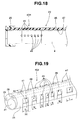
- Fig. 19 to Fig. 21 relate to another modification example of the sheath bending portion.
- Fig. 19 is a perspective view that illustrates a sheath bending portion in which a plurality of communicating holes are arranged that have different length dimensions in the longitudinal direction.
- Fig. 20 is a cross-sectional view along a line XX-XX in Fig. 19 .
- Fig. 21 is a schematic diagram that illustrates the relation between the curvature of a bending portion and the plurality of kinds of communicating holes provided in the sheath bending portion.
- a sheath bending portion 40J of the present modification example includes, for example, three kinds of communicating holes 47, 48, and 49 that have different length dimensions in the longitudinal direction as shown in Fig. 19 and Fig. 20 .
- the length dimensions in the longitudinal direction of first communicating holes 47 are set as the longest dimensions.
- the length dimensions in the longitudinal direction of third communicating holes 49 are set as the shortest dimensions.
- the length dimensions in the longitudinal direction of second communicating holes 48 are set so as to be shorter than the length dimensions of the first communicating holes 47 and longer than the length dimensions of the third communicating holes 49.
- the communicating holes 47, 48, and 49 are arranged at regular intervals parallel to the longitudinal axis in consideration of the curvature of the bending portion 8. More specifically, it is desirable that communicating holes arranged in a bending portion 81 that has the largest curvature (1/r) in the bending portion 8 are holes that prevent creasing occurring when the area or the perimeter of the communicating holes changes shape significantly due to deformation. Consequently, the third communicating holes 49 are provided at positions corresponding to the bending portion 81.
- the first communicating holes 47 are provided at bending portions 8s that have the smallest curvature in the bending portion 8. Because the curvature at the bending portions 8s is small, a change in shape in the area or perimeter of the first communicating holes 47 is small.
- the second communicating holes 48 are provided at intermediate bending portions 8m that have a curvature that is greater than the bending portions 8s that have the smallest curvature and is less than the bending portion 81 that has the largest curvature.
- a configuration may also be adopted that reduces the cross-sectional area of the tube itself by providing the communicating hole 43 at a lower part of the bending portion 8 opposite to the concave portion 41, as shown in Fig. 15 , on the thin-walled region 26b side.
Landscapes
- Health & Medical Sciences (AREA)
- Life Sciences & Earth Sciences (AREA)
- Physics & Mathematics (AREA)
- Surgery (AREA)
- Optics & Photonics (AREA)
- Biomedical Technology (AREA)
- Animal Behavior & Ethology (AREA)
- Radiology & Medical Imaging (AREA)
- Nuclear Medicine, Radiotherapy & Molecular Imaging (AREA)
- Engineering & Computer Science (AREA)
- Biophysics (AREA)
- Heart & Thoracic Surgery (AREA)
- Medical Informatics (AREA)
- Molecular Biology (AREA)
- Pathology (AREA)
- General Health & Medical Sciences (AREA)
- Public Health (AREA)
- Veterinary Medicine (AREA)
- General Physics & Mathematics (AREA)
- Astronomy & Astrophysics (AREA)
- Endoscopes (AREA)
- Instruments For Viewing The Inside Of Hollow Bodies (AREA)
Abstract
Description
- The present invention relates to an endoscope cleaning sheath that sprays a mixed fluid in an atomized state at an observation window or the like of an endoscope to remove adherents that adhere to the observation window or the like.
- When in-vivo mucus, blood, fat, dirt or the like adhere to an observation window or illuminating window or the like of an endoscope during endoscopic observation, favorable observation is hindered.
- Japanese Patent Application Laid-Open Publication No.
2008-132282 - It is conventionally known that superior cleaning performance can be obtained by spraying a mixed fluid in an atomized state from an ejection nozzle towards an outer surface of an observation window in comparison to a case of spraying only water at the outer surface of the observation window. A sheath for cleaning an endoscope disclosed in Japanese Patent Application Laid-Open Publication No.
2008-093173 - The sheath for cleaning an endoscope mainly includes, in order from the distal end side thereof, a distal-end structure section and a tube body. A hole through which the insertion portion of the endoscope is inserted and a plurality of fluid conduits that serve as conduits for water or air are provided in the tube body.
- When the endoscope is an endoscope with a bending mechanism that includes a bending portion in the insertion portion, the sheath body portion or tube body included in the sheath for cleaning an endoscope is constituted by a flexible multi-lumen tube. It is thereby possible for the bending portion to bend in a state in which the sheath for cleaning an endoscope is mounted to the endoscope.
- However, when the endoscope cleaning sheath is mounted to the endoscope with the bending mechanism, the multi-lumen tube makes resistance although it is flexible. And, in the case where the fluid conduits of the multi-lumen tube are located close to a bending direction of the bending portion, the multi-lumen tube on an inner peripheral side of the bending is squeezed in the direction of being compressed to form a corrugation. When the bending portion is further bent, the corrugation develops to form a plurality of large corrugations or a meander portion. Then, there arises a possibility that the fluid conduits provided in the multi-lumen tube are collapsed by the meander portion to make the supply of the fluid unstable. Further, a force to return to the original shape is generated in the multi-lumen tube itself since the meander portion is formed and the multi-lumen tube on the outer circumferential side of the bending is pulled to be expanded. The multi-lumen tube exerts a load on an operation for bending the bending portion by the force to return to the original shape applied to the multi-lumen tube itself, and there arise problems of lowering operability of a bending knob, lowering a limit value of a bending angle of the bending portion, and causing breakage of a wire for bending the bending portion.
- The present invention has been made in view of the above circumstances and an object of the present invention is to provide an endoscope cleaning sheath capable of performing an operation for bending a bending portion which is provided in an endoscope with a bending mechanism to which the endoscope cleaning sheath is mounted, and performing removal of dirt adhered to an observation window or the like of the endoscope by spray in a state where the bending portion is bent.
- An endoscope cleaning sheath of the present invention includes a flexible tube body that is mounted to an insertion portion having a bending portion included in an endoscope and that has a plurality of through-holes that are parallel to a longitudinal axis, and a cylindrical distal-end structure section that is provided at a distal end portion of the flexible tube body and that sprays at least one of a gas and a liquid at least at an observation window provided at a distal end portion of the insertion portion of the endoscope, wherein: the through-holes are a hole for an endoscope insertion portion through which the insertion portion of the endoscope is inserted, and at least a first fluid conduit that supplies the gas and a second fluid conduit that supplies the liquid; the first fluid conduit and the second fluid conduit are provided at positions in a direction that is different from a bending direction of the bending portion of the insertion portion that is inserted and disposed in the hole for an endoscope insertion portion.
-
-
Fig. 1 to Fig. 5 relate to a first embodiment of the present invention. -
Fig. 1 is a view that illustrates an endoscope apparatus that includes a rigid endoscope with a bending function and a cleaning sheath; -
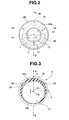
Fig. 2 is a front view of a state in which an insertion portion of the endoscope is inserted through a hole for an endoscope insertion portion of the cleaning sheath; -
Fig. 3 is a cross-sectional view along a line III-III inFig. 1 that illustrates a configuration of a multi-lumen tube included in the cleaning sheath; -
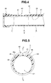
Fig. 4 is a view showing a state in which the insertion portion of the endoscope is mounted in a hole for an endoscope insertion portion of the endoscope cleaning sheath; -
Fig. 5 is a cross-sectional view along a line V-V inFig. 1 that illustrates a sheath bending portion that has a concave portion in an upper outer circumferential face between conduits of the multi-lumen tube; -
Fig. 6 is a cross-sectional view that illustrates a sheath bending portion in which a concave portion that faces a concave portion provided in the upper outer circumferential face between conduits of the multi-lumen tube is provided in a lower outer circumferential face; -
Fig. 7 is a cross-sectional view relating to a modification example of the sheath bending portion, that illustrates a sheath bending portion in which a plurality of concave portions are arranged; -
Fig. 8 is a cross-sectional view relating to another modification example of the sheath bending portion, that illustrates a sheath bending portion that has a concave portion in an outer circumferential face between upper conduits of a multi-lumen tube and in an inner circumferential face of a hole for an endoscope insertion portion; -
Fig. 9 is a cross-sectional view relating to another modification example of the sheath bending portion, that illustrates a sheath bending portion that has a plurality of concave portions in an outer circumferential face of a multi-lumen tube; -
Fig. 10 is a cross-sectional view relating to a further modification example of the sheath bending portion, that illustrates a sheath bending portion that has a plurality of concave portions in the outer circumferential face of a multi-lumen tube and in the inner circumferential face of a hole for an endoscope insertion portion, respectively; -
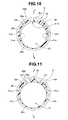
Fig. 11 is a cross-sectional view relating to a further modification example of the example shown inFig. 9 , that illustrates a sheath bending portion that has a plurality of concave portions in an outer circumferential face between respective conduits of a multi-lumen tube; and -
Fig. 12 is a cross-sectional view relating to a further modification example of the example shown inFig. 11 , that illustrates a sheath bending portion that has a plurality of concave portions in an outer circumferential face between respective conduits of a multi-lumen tube and in an inner circumferential face of a hole for an endoscope insertion portion. -
Fig. 13 andFig. 14 relate to a second embodiment of the present invention. -
Fig. 13 is a view that illustrates a cleaning sheath that has a sheath bending portion of a different configuration; -
Fig. 14 is a cross-sectional view along a line XIV-XIV inFig. 13 ; and -
Fig. 15 is a cross-sectional view that illustrates a sheath bending portion in which a communicating hole is provided in a lower part that faces a communicating hole provided in an upper direction between conduits of a multi-lumen tube. -
Fig. 16 to Fig. 18 relate to a modification example of the sheath bending portion. -
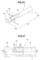
Fig. 16 is a perspective view that illustrates a sheath bending portion in which a plurality of communicating holes are arranged; -
Fig. 17 is a view of an insertion portion mounting section as viewed from an upper direction; and -
Fig. 18 is a cross-sectional view along a line XVIII-XVIII inFig. 17 . -
Fig. 19 to Fig. 21 relate to another modification example of the sheath bending portion. -
Fig. 19 is a perspective view that illustrates a sheath bending portion in which a plurality of communicating holes are arranged that have different length dimensions in the longitudinal direction; -
Fig. 20 is a cross-sectional view along a line XX-XX inFig. 19 ; and -
Fig. 21 is a view that illustrates the relation between the curvature of the bending portion and a plurality or kinds of communicating holes that are provided in the sheath bending portion. - Embodiments of the present invention are described hereunder with reference to the drawings.
- A first embodiment of the present invention will be described referring to
Fig. 1 to Fig. 5 . - As shown in
Fig. 1 , anendoscope apparatus 1 of the present embodiment mainly includes a rigid endoscope with a bending function (hereunder, abbreviated to "endoscope") 2 and an endoscope cleaning sheath (hereunder, abbreviated to "cleaning sheath") 3. - The
endoscope 2 includes aninsertion portion 4, anoperation portion 5, and auniversal cord 6. Theuniversal cord 6 extends from theoperation portion 5 and is connected to a video processor that is an external apparatus. The video processor performs signal processing of video signals that are picked up with an image pickup device denoted byreference numeral 14 inFig. 2 , control for adjusting the gain of theimage pickup device 14 and the like, and output of a driving signal for driving. Theoperation portion 5 is provided at the rear end of theinsertion portion 4. Abending knob 10 and various switches are provided in theoperation portion 5. The various switches include switches that control the image pickup device and, for example, instruct the image pickup device to perform image pickup operations such as a freeze operation and a release operation. - The
insertion portion 4 includes, in order from the distal end side, a rigiddistal end portion 7, abendable bending portion 8, and a rigid and elongatedrigid portion 9. In the present embodiment, thebending portion 8, for example, bends in the upward and downward directions as indicted by an arrow U and an arrow D in the figures. More specifically, thebending portion 8 is configured so that, when the surgeon appropriately operates thebending knob 10, thebending portion 8 bends in the upward direction or the downward direction in accordance with the relevant operation. - The bending directions of the bending
portion 8 are not limited to the upward and downward directions, and the bendingportion 8 may be configured to bend in the upward and downward directions as well as the left and right directions and the like. - As shown in
Fig. 2 , an illuminatingwindow 12 for emitting illuminating light and anobservation window 13 for performing observation are provided in a distal end face 11 of thedistal end portion 7 of theendoscope 2. An optical image incident on theobservation window 13 forms an image on a light-receiving face of theimage pickup device 14 provided inside thedistal end portion 7. A video signal picked up by theimage pickup device 14 is subjected to signal processing by the video processor and is thereafter displayed on a screen of an unshown display apparatus. - The light-receiving face of the
image pickup device 14 is orthogonally arranged with respect to the longitudinal axis of theinsertion portion 4. A vertical transfer direction V of theimage pickup device 14 matches the vertical direction of the screen, and a lateral direction matches a horizontal transfer direction H. Specifically, the vertical directions of an endoscope image picked up by theimage pickup device 14 match the vertical and lateral directions of the screen. - The vertical directions of the bending
portion 8 included in theinsertion portion 4 are set so as to correspond to the vertical and lateral directions of an endoscope image displayed on the screen. More specifically, the vertical directions of the bendingportion 8 correspond to the vertical directions of an endoscope image displayed on the screen. Accordingly, when the surgeon operates the bendingknob 10 to bend the bendingportion 8 in the downward direction, the bendingportion 8 bends in the downward direction accompanying that operation. At such time, the endoscope image that is being displayed on the screen changes accompanying the bending of the bendingportion 8 so as to allow observation in the downward direction. - As shown in
Fig. 1 , the cleaningsheath 3 mainly includes a mountingsection 21 and afluid supply portion 22. - The mounting
section 21 includes an insertionportion mounting section 23 and an operationportion attaching section 24. The insertionportion mounting section 23 includes adistal end nozzle 25 as a distal-end structure section and amulti-lumen tube 26. Themulti-lumen tube 26 includes a plurality of through-holes that are elongated parallel to the longitudinal axis. Themulti-lumen tube 26 is a flexible tube body that has a cross section as shown inFig. 3 . - The
multi-lumen tube 26 includes asheath bending portion 40 on thedistal end nozzle 25 side that is one end portion. The through-holes of themulti-lumen tube 26 are a large-diameter hole for anendoscope insertion portion 27 and a pair of small-diameter fluid conduits endoscope insertion portion 27 is an insertion passage through which theinsertion portion 4 of theendoscope 2 is inserted. The firstfluid conduit 28 is a gas delivery conduit for supplying a gas, and the secondfluid conduit 29 is a liquid delivery conduit for supplying a liquid. - A
central axis 02 of the hole for anendoscope insertion portion 27 is eccentric with respect to a central axis O1 of themulti-lumen tube 26 as indicated by arrows in the Y-axis direction inFig. 3 . Accordingly, in themulti-lumen tube 26, the wall thickness at the circumference of the hole for anendoscope insertion portion 27 differs between the upper side and lower side in theFig. 3 in a manner that sandwiches the X axis inFig. 3 . Themulti-lumen tube 26 hasfluid conduits walled region 26a that has a thick wall thickness. Thefluid conduits cleaning sheath 3, the direction of an arrow A is set as the upward direction and the direction of an arrow B is set as the downward direction in a manner that sandwiches the Y axis. - In this connection,
reference numeral 26b denotes a thin-walled region. The thin-walled region 26b is a section at which the wall thickness of themulti-lumen tube 26 is thin. The thin-walled region 26b has a configuration in which the cross-sectional area is reduced to facilitate expansion of themulti-lumen tube 26 and decrease a reactive force of the tube itself to lessen the load at the time of bending. - As shown in
Fig. 1 , thesheath bending portion 40 is provided in a bendingportion disposition area 26c on a distal end side of themulti-lumen tube 26. Therefore, when theinsertion portion 4 of theendoscope 2 is inserted into and disposed inside the hole for anendoscope insertion portion 27 as shown inFig. 4 , the circumference of the bendingportion 8 is covered by thesheath bending portion 40. At this time, the vertical direction of the bendingportion 8 matches the vertical direction of themulti-lumen tube 26. - As shown in
Fig. 1 andFig. 5 , thesheath bending portion 40 is provided with aconcave portion 41 that is elongated parallel to the longitudinal axis of themulti-lumen tube 26. Theconcave portion 41 is provided in an upper outer circumferential face between the firstfluid conduit 28 and the secondfluid conduit 29 of themulti-lumen tube 26. - The
concave portion 41 is a recessed part that reduces the thickness of the thick-walled region 26a in the upper direction of themulti-lumen tube 26. Theconcave portion 41 serves to reduce a resistance such as a load applied to a bending operation when the bendingportion 8 is bent. Theconcave portion 41 is set so as to secure a wall thickness of a predetermined amount at the circumference of thefluid conduits portion 8 is bent in the upward direction, although a force in a direction that compresses the tube is applied to the tube, theconcave portion 41 changes shape and absorbs a force that attempts to push and contract the tube. As a result, a meandering portion is formed in the surface of themulti-lumen tube 26 that is disposed on the inner circumferential side of the bending portion, and crushing of thefluid conduits - The length dimensions in the longitudinal direction of the
concave portion 41 are approximately the same as those in the longitudinal direction of the bendingportion disposition area 26c. The width dimensions of theconcave portion 41 are appropriately set in consideration of the wall thickness around thefluid conduits - The
distal end nozzle 25 is cylindrical, and is fixedly provided at the distal end portion of themulti-lumen tube 26. Thedistal end nozzle 25 has a distalend face portion 25a that is formed by notching in a predetermined shape as shown inFig. 2 . The inner face of the distalend face portion 25a is configured so as to contact with the distal end face 11 of thedistal end portion 7. A T-shaped groove (not shown) that constitutes a flow channel is formed in the inner face of the distalend face portion 25a. For example, at least one of water and air is supplied via thefluid conduits 2008-93173 - The operation
portion attaching section 24 is cylindrical as shown inFig. 1 . The operationportion attaching section 24 has an unshown concave portion with which adistal end portion 5a of theoperation portion 5 engages. For example, a convex portion that serves as a positioning portion is provided at a predetermined position in the concave portion. The convex portion is, for example, formed at a position that corresponds to the upward direction of themulti-lumen tube 26. The convex portion is engagingly inserted into aconcave portion 5b formed in thedistal end portion 5a of theoperation portion 5. Theconcave portion 5b is formed at a position that corresponds to the upward direction of the bendingportion 8. - The
fluid supply portion 22 includes aspray switch 30, and a firstgas delivery tube 31, a firstliquid feed tube 32, a secondgas delivery tube 33, and a secondliquid feed tube 34 that are fluid tubes that have one end and another end. - One end portion of the first
gas delivery tube 31 is connected to a predetermined position of, for example, a distal end sideconvex portion 24a of the operationportion attaching section 24. One end portion of the firstliquid feed tube 32 is connected to a predetermined position of, for example, the distal end sideconvex portion 24a of the operationportion attaching section 24. Thegas delivery tube 31 communicates with the firstfluid conduit 28, and theliquid feed tube 32 communicates with the secondfluid conduit 29. - Another end portion of the first
gas delivery tube 31 is connected to a gas outlet of thespray switch 30, and another end portion of the firstliquid feed tube 32 is connected to a liquid outlet of thespray switch 30. - Further, one end portion of the second
gas delivery tube 33 is connected to a gas inlet of thespray switch 30, and one end portion of the secondliquid feed tube 34 is connected to a liquid inlet of thespray switch 30. Another end portion of the secondgas delivery tube 33 is connected to an unshown gas feed pump, and another end portion of the secondliquid feed tube 34 is connected to an unshown liquid feed tank. - The
spray switch 30 has aswitching button 35 that can perform a switching operation in two stages. According to the present embodiment, when the surgeon performs an operation to push in theswitching button 35 as far as a first stage, a gas is ejected from thedistal end nozzle 25 towards theobservation window 13 or the like. Further, when the surgeon performs an operation to push in theswitching button 35 as far as a second stage, a mixed fluid formed by mixing air and water is sprayed from thedistal end nozzle 25 towards theobservation window 13 or the like. - Next, mounting of the cleaning
sheath 3 to theinsertion portion 4 is described. - The user mounts the cleaning
sheath 3 to theinsertion portion 4 of theendoscope 2. At that time, the user inserts the distal end of theinsertion portion 4 into the hole for anendoscope insertion portion 27 of themulti-lumen tube 26 included in thecleaning sheath 3 from the operationportion attaching section 24 side. At such time, the user matches the vertical direction of the cleaningsheath 3 with the vertical direction of the bendingportion 8. - The user integrally attaches the operation
portion attaching section 24 of the cleaningsheath 3 to theoperation portion 5 of theendoscope 2. Finally, the user engages the convex portion of the operationportion attaching section 24 with theconcave portion 5b formed in thedistal end portion 5a. As a result, the inner face of the distalend face portion 25a of thedistal end nozzle 25 contacts the distal end face 11 of thedistal end portion 7, to thereby complete mounting of the cleaningsheath 3 to theinsertion portion 4. - In this mounted state, the
sheath bending portion 40 covers the circumference of the bendingportion 8. Further, as shown inFig. 2 , because the vertical direction of the bendingportion 8 and the vertical direction of the cleaningsheath 3 match, theconcave portion 41 of thesheath bending portion 40 is disposed in the upper direction of the bendingportion 8 and thefluid conduits cleaning sheath 3 are arranged at positions that are in a different direction from the bending direction of the bendingportion 8 of theendoscope 2. - When the surgeon appropriately operates the bending
knob 10 in this mounted state, the bendingportion 8 that is covered by themulti-lumen tube 26 of the cleaningsheath 3 bends in the upward direction or downward direction in accordance with the operation of the bendingknob 10. At this time, since thefluid conduits portion 8 of theendoscope 2 as described above, crushing of thefluid conduits portion 8 can be prevented. Thus, a problem whereby thefluid conduits cleaning sheath 3 are flattened accompanying the bending of the bendingportion 8 and it is difficult to secure a flow quantity is prevented. - Further, as described above, the
concave portion 41 of thesheath bending portion 40 that covers the circumference of the bendingportion 8 is positioned in the upper direction of the bendingportion 8, and the thin-walled region 26b is positioned in the lower direction of the bendingportion 8. Accordingly, a bending operation of the bendingportion 8 can be smoothly performed by operating the bendingknob 10. In addition, when the bendingportion 8 has been bent, it is possible to prevent the occurrence of a meandering portion at the inner circumferential side thereof. - By means of the
concave portion 41, the resistance of the thick-walled region 26a of themulti-lumen tube 26 is reduced and the wall thickness of thefluid conduits portion 8 is secured. Accordingly, when the bendingportion 8 has been bent in the upward direction, even if slackness or creasing occurs in themulti-lumen tube 26 that is disposed on the inner circumferential side of the bendingportion 8, a compressive force applied to the thick-walled region 26a decreases. Hence, it is possible to prevent creasing generated in themulti-lumen tube 26 from changing shape into a meandering portion that crushes thefluid conduits fluid conduits - A configuration may also be adopted in which a
concave portion 41 is provided that reduces the amount of force applied to the thick-walled region 26a and in which, as shown inFig. 6 , on the thin-walled region 26b side, aconcave portion 41 is provided at a lower part of the bendingportion 8 facing theconcave portion 41 to thereby decrease the cross-sectional area of the tube itself. - Thus, when the bending
portion 8 is bent, a force that attempts to push and contract themulti-lumen tube 26 that arises on the inner circumferential side of the bend and a force that attempts to expand themulti-lumen tube 26 that arises on the outer circumferential side of the bend can be simultaneously reduced, so that an effect can be exerted that reduces a load applied to the bendingportion 8 to the maximum degree. - Note that the configuration of the
sheath bending portion 40 provided in themulti-lumen tube 26 is not limited to the above described configuration in which a concave portion that is parallel to the longitudinal axis is provided at an upper outer circumferential face between the firstfluid conduit 28 and the secondfluid conduit 29 of themulti-lumen tube 26 or at outer circumferential faces in the upper and lower directions, and the sheath bending portion may have the same configuration as a sheath bending portion illustrated inFig. 7 to Fig. 12 that are described hereunder. - Hereunder, another configuration example of the sheath bending portion is described with reference to the drawings.
-
Fig. 7 relates to a modification example of the sheath bending portion, and is a cross-sectional view that illustrates a sheath bending portion in which a plurality of concave portions are arranged. - In a
sheath bending portion 40A of the present modification example, instead of aconcave portion 41 provided parallel to the longitudinal axis, a plurality ofconcave portions 42 that are elongated in a circumferential direction are, for example, arranged at regular intervals parallel to the longitudinal axis. - By providing a plurality of
concave portions 42 on the upper outer circumferential face of themulti-lumen tube 26 in this manner, actions and effects that are similar to those of the above described first embodiment can be obtained. -
Fig. 8 relates to another modification example of the sheath bending portion, and is a cross-sectional view that illustrates a sheath bending portion that has a concave portion in an outer circumferential face between conduits provided in the upper direction of the multi-lumen tube and in an inner circumferential face of a hole for an endoscope insertion portion. - A
sheath bending portion 40B of the present modification example includesconcave portions fluid conduit 28 and the secondfluid conduit 29 and in an inner circumferential face in the upper direction of themulti-lumen tube 26. - By providing the
concave portion 41a in the upper outer circumferential face and providing theconcave portion 41b in an inner circumferential face in the upper direction of themulti-lumen tube 26 in this manner, actions and effects that are similar to those of the above described embodiments can be obtained. -
Fig. 9 relates to a further modification example of the sheath bending portion, and is a cross-sectional view that illustrates a sheath bending portion that has a plurality of concave portions in the outer circumferential face of the multi-lumen tube. - In addition to the
concave portion 41 parallel to the longitudinal axis that is provided between the firstfluid conduit 28 and the secondfluid conduit 29 of themulti-lumen tube 26, asheath bending portion 40C of the present modification example includes, for example, a pair ofconcave portions 41c that are parallel to the longitudinal axis in the thick-walled region 26a of the outer circumferential face between conduits in the downward direction from thefluid conduits - By providing the
concave portion 41 andconcave portions 41c in the outer circumferential face of themulti-lumen tube 26 in this manner, actions and effects that are similar to those of the above described embodiments can be obtained. -
Fig. 10 relates to a further modification example of the sheath bending portion, and is a cross-sectional view that illustrates a sheath bending portion that has a plurality of concave portions in the outer circumferential face of a multi-lumen tube and in an inner circumferential face of a hole for an endoscope insertion portion, respectively. - In addition to the
concave portion 41a parallel to the longitudinal axis that is provided in the upper outer circumferential face and theconcave portion 41b parallel to the longitudinal axis that is provided in the inner circumferential face in the upward direction, asheath bending portion 40D of the present modification example also includes a pair ofconcave portions 41d that are parallel to the longitudinal axis in the outer circumferential face of the thick-walled region 26a between the conduits in the downward direction from thefluid conduits concave portions 41e that are parallel to the longitudinal axis in the inner circumferential face of themulti-lumen tube 26. - By providing the
concave portion 41a andconcave portions 41d in the outer circumferential face and providing theconcave portion 41b and theconcave portions 41e in the inner circumferential face of themulti-lumen tube 26 in this manner, actions and effects that are similar to those of the above described embodiments can be obtained. - A configuration may also be adopted as shown in
Fig. 11 in which asheath bending portion 40E includesconcave portions multi-lumen tube 26 at positions that are in a different direction from the bending direction of the bendingportion 8. Thesheath bending portion 40E includes theconcave portions walled region 26a between upper conduits and between lower conduits composed between the firstfluid conduit 28 and the secondfluid conduit 29. - Further, a
sheath bending portion 40F shown inFig. 12 includes, in addition to theconcave portions concave portion 41k and a plurality ofconcave portions 41 m that are parallel to the longitudinal axis and that are provided in the inner circumferential face of the hole for anendoscope insertion portion 27 to uniformize the wall thickness at the circumference of the hole for anendoscope insertion portion 27. - By providing the
concave portions multi-lumen tube 26 in this manner, actions and effects that are similar to those of the above described embodiments can be obtained. - Note that, in the embodiments illustrated in
Fig. 7 to Fig. 12 , a configuration may be adopted that reduces the cross-sectional area of the tube itself by providing aconcave portion 41 at a lower part of the bendingportion 8 opposite to theconcave portion 41, as shown inFig. 6 , on the thin-walled region 26b side. - In this connection, the above described
Fig. 11 relates to an additional modification example of the above describedFig. 9 , and is a cross-sectional view that illustrates a sheath bending portion having a plurality of concave portions in the outer circumferential face between the conduits of the multi-lumen tube. Furthermore, the above describedFig. 12 relates to an additional modification example of the above describedFig. 11 , and is a cross-sectional view that illustrates a sheath bending portion having a plurality of concave portions in the outer circumferential face between the conduits of the multi-lumen tube and in the inner circumferential face of the hole for an endoscope insertion portion. -
Fig. 13 andFig. 14 relate to a second embodiment of the present invention.Fig. 13 is a view that illustrates a cleaning sheath that has a sheath bending portion of a different configuration.Fig. 14 is a cross-sectional view along a line XIV-XIV inFig. 13 . - In a
cleaning sheath 3A of the present embodiment, asheath bending portion 40G provided in themulti-lumen tube 26 includesholes - More specifically, as shown in
Fig. 13 andFig. 14 , thesheath bending portion 40G of the present embodiment includes communicatingholes multi-lumen tube 26. The communicatinghole 43 is a single hole that allows the outside of themulti-lumen tube 26 to communicate with the inside of the hole for anendoscope insertion portion 27. The communicatinghole 43 is provided in the upper outer circumferential face between the firstfluid conduit 28 and the secondfluid conduit 29 of themulti-lumen tube 26. Two communicatingholes 44 are provided. The firstfluid conduit 28 is arranged between one of the communicatingholes 44 and the communicatinghole 43, and the secondfluid conduit 29 is arranged between the other communicatinghole 44 and the communicatinghole 43. - The length and width dimensions in the circumferential direction of the communicating
holes hole 43 is less than a distal end face area of thedistal end portion 7 of theendoscope 2 or so that the perimeter of the opening of the communicatinghole 43 is shorter than the perimeter of thedistal end portion 7. Thus, theinsertion portion 4 of theendoscope 2 is prevented from protruding to outside from the hole for anendoscope insertion portion 27 of thecleaning sheath 3A through the communicatinghole 43. - The other components are the same as in the first embodiment, and like members are denoted by like reference numerals and a description of such members is omitted hereunder.
- In a state in which the insertion
portion mounting section 23 of thecleaning sheath 3A is mounted to theinsertion portion 4, thesheath bending portion 40G covers the circumference of the bendingportion 8 similarly to the first embodiment. According to the present embodiment, when the surgeon appropriately operates the bendingknob 10, the bendingportion 8 that is covered by themulti-lumen tube 26 of the cleaningsheath 3 A bends in the upward direction or downward direction accompanying the operation of the bendingknob 10. - In the present embodiment also, since the communicating
hole 43 of thesheath bending portion 40G that covers the circumference of the bendingportion 8 is positioned in the upper direction of the bendingportion 8, and the thin-walled region 26b is positioned in the lower direction thereof, a bending operation of the bendingportion 8 can be smoothly performed by operating the bendingknob 10. In addition, the occurrence of a meandering portion on the inner circumferential side of the bendingportion 8 can be prevented. - Further, the resistance of the thick-
walled region 26a of themulti-lumen tube 26 is decreased by means of the communicatingholes fluid conduits portion 8 is secured. Accordingly, when the bendingportion 8 is bent in the upward direction, if slackness or creasing occurs between the communicatinghole 43 and communicatingholes 44 of themulti-lumen tube 26 disposed on the inner circumferential side of the bendingportion 8, thefluid conduits hole 43 side or the communicatingholes 44 side accompanying the occurrence of creasing, and crushing of thefluid conduits - A configuration may also be adopted in which a communicating
hole 43 that decreases a force amount is provided in the upper outer circumferential face between the firstfluid conduit 28 and the secondfluid conduit 29 that is the thick-walled region 26a of themulti-lumen tube 26 and, as shown inFig. 15 , on the thin-walled region 26b side, a communicatinghole 43 is provided in the lower outer circumferential face below the bendingportion 8 at a position facing the communicatinghole 43 provided on the upper side to thereby decrease the cross-sectional area of the tube itself. - Thus, when the bending
portion 8 is bent, a force that attempts to push and contract themulti-lumen tube 26 that arises on the inner circumferential side of the bend and a force that attempts to expand themulti-lumen tube 26 that arises on the outer circumferential side of the bend can be simultaneously reduced, and an effect can be exerted that reduces the load applied to the bend to the maximum degree. - In this connection, the configuration of the
sheath bending portion 40G is not limited to a configuration in which the communicatingholes sheath bending portion 40G may have the same configuration as a sheath bending portion that is illustrated inFig. 16 to Fig. 21 as described hereunder. - A configuration example of the sheath bending portion is described hereunder referring to the drawings.
-
Fig. 16 to Fig. 18 relate to a modification example of the sheath bending portion.Fig. 16 is a perspective view that illustrates a sheath bending portion in which a plurality of communicating holes are arranged.Fig. 17 is a view of an insertion portion mounting section as seen from the upper direction.Fig. 18 is a cross-sectional view along a line XVI-XVI inFig. 17 . - As shown in
Fig. 16 to Fig. 18 , asheath bending portion 40H of the present modification example includes a plurality of communicatingholes 45 that are elongated in the circumferential direction instead of the communicatinghole 43 that is a long hole parallel to the longitudinal axis. Thesheath bending portion 40H also includes a plurality of communicatingholes 46 that are elongated in the circumferential direction instead of the communicatingholes 44 that are long holes parallel to the longitudinal axis. The plurality of communicatingholes - Thus, a plurality of communicating
holes 45 that are elongated in the circumferential direction and are parallel to the longitudinal axis are provided in the upper outer circumferential face of themulti-lumen tube 26, a plurality of communicatingholes 46 are provided so as to sandwich thefluid conduit 28 between the communicatingholes 45 and the communicatingholes 46, and a plurality of communicatingholes 46 are provided so as to sandwich thefluid conduit 29 between the communicatingholes 45 and the communicating holes 46. Therefore, when a compressive force acts on themulti-lumen tube 26 disposed on the inner circumferential side of the bendingportion 8, the plurality of communicatingholes 45 and the plurality of communicatingholes 46 respectively absorb and decrease the force applied to themulti-lumen tube 26 so that the occurrence of creasing or a meandering portion can be prevented. As a result, treatment instruments no longer stick in a meandering portion. Further, when extracting theendoscope 2 from a trocar, a creased portion does not stick to the mouth of the trocar. -
Fig. 19 to Fig. 21 relate to another modification example of the sheath bending portion.Fig. 19 is a perspective view that illustrates a sheath bending portion in which a plurality of communicating holes are arranged that have different length dimensions in the longitudinal direction.Fig. 20 is a cross-sectional view along a line XX-XX inFig. 19 .Fig. 21 is a schematic diagram that illustrates the relation between the curvature of a bending portion and the plurality of kinds of communicating holes provided in the sheath bending portion. - A
sheath bending portion 40J of the present modification example includes, for example, three kinds of communicatingholes Fig. 19 andFig. 20 . The length dimensions in the longitudinal direction of first communicatingholes 47 are set as the longest dimensions. The length dimensions in the longitudinal direction of third communicatingholes 49 are set as the shortest dimensions. The length dimensions in the longitudinal direction of second communicatingholes 48 are set so as to be shorter than the length dimensions of the first communicatingholes 47 and longer than the length dimensions of the third communicating holes 49. - As shown in
Fig. 21 , the communicatingholes portion 8. More specifically, it is desirable that communicating holes arranged in a bendingportion 81 that has the largest curvature (1/r) in the bendingportion 8 are holes that prevent creasing occurring when the area or the perimeter of the communicating holes changes shape significantly due to deformation. Consequently, the third communicatingholes 49 are provided at positions corresponding to the bendingportion 81. Thus, in a region in which the bendingportion 8 has a large curvature, a significant deformation of the third communicatingholes 49 of thesheath bending portion 40J is prevented so that the occurrence of slackness or creasing at the circumference thereof can be prevented. - On the other hand, the first communicating
holes 47 are provided at bendingportions 8s that have the smallest curvature in the bendingportion 8. Because the curvature at the bendingportions 8s is small, a change in shape in the area or perimeter of the first communicatingholes 47 is small. The second communicatingholes 48 are provided atintermediate bending portions 8m that have a curvature that is greater than the bendingportions 8s that have the smallest curvature and is less than the bendingportion 81 that has the largest curvature. - By disposing the plurality of communicating
holes portion 8 in this manner, it is possible to prevent the occurrence of a meandering portion in thesheath bending portion 40J that is positioned on the inner circumferential side of the bendingportion 8 and also reduce the bending resistance. - Note that, in the embodiments illustrated in
Fig. 16 to Fig. 21 , a configuration may also be adopted that reduces the cross-sectional area of the tube itself by providing the communicatinghole 43 at a lower part of the bendingportion 8 opposite to theconcave portion 41, as shown inFig. 15 , on the thin-walled region 26b side. - It should be understood that the present invention is not limited only to the above described embodiments, and various changes and modifications thereof could be made without departing from the spirit or scope of the invention.
- The present application is filed claiming the priority of Japanese Patent Application No.
2009-147897
Claims (7)
- An endoscope cleaning sheath, comprising:a flexible tube body that is mounted to an insertion portion having a bending portion included in an endoscope, and that comprises a plurality of through-holes that are parallel to a longitudinal axis; anda cylindrical distal end nozzle that is provided at a distal end portion of the flexible tube body and that sprays at least one of a gas and a liquid at least at an observation window provided at a distal end portion of the insertion portion of the endoscope;wherein:the through-holes are a hole for an endoscope insertion portion through which the insertion portion of the endoscope is inserted, and at least a first fluid conduit that supplies the gas and a second fluid conduit that supplies the liquid; andthe first fluid conduit and the second fluid conduit are provided at positions in a direction that is different from a bending direction of the bending portion of the insertion portion that is inserted and disposed in the hole for an endoscope insertion portion.
- The endoscope cleaning sheath according to claim 1, wherein the flexible tube body comprises a sheath bending portion that covers a circumference of the bending portion of the insertion portion that is inserted and disposed in the hole for an endoscope insertion portion, and the sheath bending portion includes at least one concave portion or hole that decreases a bending resistance of the sheath bending portion to a resistance that is less than a bending resistance of the flexible tube body.
- The endoscope cleaning sheath according to claim 2, wherein the concave portion is provided in at least one of an outer circumferential face of the flexible tube body that is positioned between the first fluid conduit and the second fluid conduit, and an inner circumferential face of the hole for an endoscope insertion portion that is positioned between the first fluid conduit and the second fluid conduit.
- The endoscope cleaning sheath according to claim 3, wherein a plurality of the concave portions are provided in the outer circumferential face of the flexible tube body or a plurality of the concave portions are provided in the inner circumferential face of the hole for an endoscope insertion portion.
- The endoscope cleaning sheath according to claim 2, wherein the hole is at least one communicating hole that allows outside of the flexible tube body to communicate with the hole for an endoscope insertion portion.
- The endoscope cleaning sheath according to claim 5, wherein a perimeter of an opening of the communicating hole is set so as to be shorter than a perimeter of the distal end portion of the insertion portion of the endoscope, or an area of the opening of the communicating hole is set so as to be less than an area of a distal end face of the insertion portion of the endoscope.
- The endoscope cleaning sheath according to claim 5, wherein,
in a configuration in which a plurality of the communicating holes are arranged in a longitudinal direction in the sheath bending portion of the flexible tube body,
a perimeter or an area of the communicating holes provided in the sheath bending portion is set in accordance with a curvature of the bending portion, and the perimeter or the area of the communicating holes is set to a larger value in accordance with a decrease in the curvature of the bending portion.
Applications Claiming Priority (2)
| Application Number | Priority Date | Filing Date | Title |
|---|---|---|---|
| JP2009147897 | 2009-06-22 | ||
| PCT/JP2010/059911 WO2010150666A1 (en) | 2009-06-22 | 2010-06-11 | Endoscope flushing sheath |
Publications (2)
| Publication Number | Publication Date |
|---|---|
| EP2446801A1 true EP2446801A1 (en) | 2012-05-02 |
| EP2446801A4 EP2446801A4 (en) | 2014-03-05 |
Family
ID=43386438
Family Applications (1)
| Application Number | Title | Priority Date | Filing Date |
|---|---|---|---|
| EP10791984.7A Withdrawn EP2446801A4 (en) | 2009-06-22 | 2010-06-11 | ENDOSCOPE RINSING SLEEVE |
Country Status (5)
| Country | Link |
|---|---|
| US (1) | US8663090B2 (en) |
| EP (1) | EP2446801A4 (en) |
| JP (1) | JP4841695B2 (en) |
| CN (1) | CN102458216B (en) |
| WO (1) | WO2010150666A1 (en) |
Families Citing this family (35)
| Publication number | Priority date | Publication date | Assignee | Title |
|---|---|---|---|---|
| JP5286049B2 (en) * | 2008-11-25 | 2013-09-11 | 富士フイルム株式会社 | Endoscope |
| US9763567B2 (en) | 2010-10-20 | 2017-09-19 | Covidien Lp | Endoscope wiper blade cleaner |
| US8690764B2 (en) | 2010-10-20 | 2014-04-08 | Covidien Lp | Endoscope cleaner |
| USD671211S1 (en) * | 2011-02-09 | 2012-11-20 | Olympus Medical Systems Corp. | Operation portion of an endoscope |
| USD685908S1 (en) * | 2011-02-17 | 2013-07-09 | Olympus Medical Systems Corp. | Endoscope |
| JP5467079B2 (en) * | 2011-07-29 | 2014-04-09 | 富士フイルム株式会社 | Endoscope insertion aid |
| US8967204B2 (en) * | 2012-08-24 | 2015-03-03 | Olympus Medical Systems Corporation | Curved pipe for endoscopes |
| JP5498629B1 (en) * | 2012-09-14 | 2014-05-21 | オリンパスメディカルシステムズ株式会社 | Endoscope cleaning sheath and endoscope apparatus |
| US9700378B2 (en) | 2013-04-26 | 2017-07-11 | Medtronic Xomed, Inc. | Endoscope lens cleaning device |
| US20150087911A1 (en) | 2013-09-26 | 2015-03-26 | Gyrus Acmi, Inc. D.B.A Olympus Surgical Technologies America | Endoscope sheath deflection devices |
| US9433468B2 (en) | 2013-10-04 | 2016-09-06 | Tidi Products, Llc | Sheath for a medical or dental instrument |
| JP6203010B2 (en) * | 2013-11-18 | 2017-09-27 | オリンパス株式会社 | Endoscope |
| USD731652S1 (en) | 2014-02-19 | 2015-06-09 | Tidi Products, Llc | Dental curing light sleeve |
| US20170156571A1 (en) * | 2014-06-25 | 2017-06-08 | Mackay Memorial Hospital | Ultrathin endoscope auxiliary system and method of use |
| US9585547B2 (en) | 2014-11-24 | 2017-03-07 | Gyrus Acmi, Inc. | Adjustable endoscope sheath |
| US9345386B1 (en) | 2014-11-24 | 2016-05-24 | Gyrus Acmi, Inc. | Adjustable endoscope sheath |
| US9782525B2 (en) | 2015-01-08 | 2017-10-10 | Gyrus Acmi, Inc. | Multi-way valve for a medical instrument |
| US20170056047A1 (en) * | 2015-09-02 | 2017-03-02 | MicroAire Surgical Instruments, LLC. | Endoscopic Surgical Devices and Other Surgical Devices |
| US12383120B2 (en) * | 2015-11-13 | 2025-08-12 | Daryl BODNER | Endoscope |
| WO2019125581A1 (en) * | 2017-12-19 | 2019-06-27 | Intuitive Surgical Operations, Inc. | Imaging systems and methods of use |
| CN110115617A (en) * | 2018-02-06 | 2019-08-13 | 上海执中医疗技术有限公司 | For the sheath of endoscope, sheath end, protective case component and endoscopic apparatus |
| US20190343376A1 (en) * | 2018-05-11 | 2019-11-14 | Hao Kenith Fang | Methods and apparatus for a cleaning sheath for an endoscope |
| JP6901636B2 (en) * | 2018-06-28 | 2021-07-14 | オリンパス株式会社 | Endoscope cleaning tool |
| US11412921B2 (en) | 2018-10-02 | 2022-08-16 | Covidien Lp | Multi lumen access device |
| CN119837476A (en) * | 2018-10-19 | 2025-04-18 | 直观外科手术操作公司 | Cleaning apparatus for imaging devices, apparatus and methods |
| JP7155396B2 (en) | 2019-03-19 | 2022-10-18 | オリンパス株式会社 | Ultrasound endoscope and insertion tube |
| EP3968837B1 (en) | 2019-05-15 | 2025-02-26 | Boston Scientific Scimed, Inc. | Medical device having asymmetric bending |
| US11357542B2 (en) | 2019-06-21 | 2022-06-14 | Covidien Lp | Valve assembly and retainer for surgical access assembly |
| US11805968B2 (en) * | 2019-11-05 | 2023-11-07 | Bayou Surgical, Inc. | Intraoperative endoscope cleaning system |
| US20220175237A1 (en) * | 2020-01-30 | 2022-06-09 | Igor Renato De Abreu | Structural arrangement applied to a rigid endoscope for cleaning the objective lens during video surgery procedure |
| US11850106B2 (en) | 2020-05-06 | 2023-12-26 | Covidien Lp | Cleaning cap for a surgical access device |
| EP4153023A1 (en) * | 2020-05-20 | 2023-03-29 | Arthrex, Inc. | Endoscopic camera sheath |
| US12004724B2 (en) | 2021-05-06 | 2024-06-11 | Medtronic Xomed, Inc. | Endoscope cleaning system |
| WO2022255805A1 (en) * | 2021-06-02 | 2022-12-08 | 계명대학교 산학협력단 | Cholangioscopy tube |
| US20260041310A1 (en) * | 2024-08-09 | 2026-02-12 | Boston Scientific Scimed, Inc. | Articulating medical devices and related methods |
Family Cites Families (17)
| Publication number | Priority date | Publication date | Assignee | Title |
|---|---|---|---|---|
| ZA945387B (en) * | 1993-07-22 | 1995-03-10 | Xomed Treace Inc | Disposable endoscope sheath |
| JP3342140B2 (en) * | 1993-12-27 | 2002-11-05 | オリンパス光学工業株式会社 | Cover-type endoscope |
| JP3300146B2 (en) * | 1993-12-29 | 2002-07-08 | オリンパス光学工業株式会社 | Endoscope treatment instrument raising device |
| JP3537180B2 (en) * | 1994-05-17 | 2004-06-14 | オリンパス株式会社 | Cover type endoscope |
| JP3514847B2 (en) * | 1994-11-25 | 2004-03-31 | オリンパス株式会社 | Endoscope |
| JPH10225435A (en) * | 1997-02-14 | 1998-08-25 | Olympus Optical Co Ltd | Cover type endoscope |
| JP3837867B2 (en) * | 1997-10-02 | 2006-10-25 | フジノン株式会社 | Endoscope flexible tube and manufacturing method thereof |
| JP3927764B2 (en) * | 2000-09-01 | 2007-06-13 | ペンタックス株式会社 | Endoscope flexible tube |
| US7762949B2 (en) * | 2003-10-16 | 2010-07-27 | Granit Medical Innovation, Llc | Endoscope with open channels |
| WO2005072402A2 (en) | 2004-01-29 | 2005-08-11 | Cannuflow, Inc. | Atraumatic arthroscopic instrument sheath |
| DE102005018825B3 (en) * | 2005-04-22 | 2007-01-04 | Polydiagnost Gmbh | endoscope |
| US8016749B2 (en) * | 2006-03-21 | 2011-09-13 | Boston Scientific Scimed, Inc. | Vision catheter having electromechanical navigation |
| JP4981403B2 (en) | 2006-10-11 | 2012-07-18 | オリンパスメディカルシステムズ株式会社 | Endoscope cleaning sheath and endoscope apparatus including the same |
| JP2008132282A (en) | 2006-11-29 | 2008-06-12 | Olympus Medical Systems Corp | Endoscope cleaning sheath |
| JP2009119064A (en) * | 2007-11-15 | 2009-06-04 | Olympus Corp | Cover type endoscope, endoscope for cover, and endoscope cover |
| EP2067433B1 (en) * | 2007-12-03 | 2013-05-01 | Olympus Medical Systems Corp. | Medical appliance, endoscope overtube and endoscope apparatus |
| TW200926702A (en) | 2007-12-12 | 2009-06-16 | Alcor Micro Corp | Apparatus and method for measuring channel state information |
-
2010
- 2010-06-11 JP JP2010543329A patent/JP4841695B2/en active Active
- 2010-06-11 CN CN201080025930.2A patent/CN102458216B/en not_active Expired - Fee Related
- 2010-06-11 EP EP10791984.7A patent/EP2446801A4/en not_active Withdrawn
- 2010-06-11 WO PCT/JP2010/059911 patent/WO2010150666A1/en not_active Ceased
- 2010-11-04 US US12/939,526 patent/US8663090B2/en active Active
Also Published As
| Publication number | Publication date |
|---|---|
| CN102458216A (en) | 2012-05-16 |
| WO2010150666A1 (en) | 2010-12-29 |
| CN102458216B (en) | 2014-03-12 |
| EP2446801A4 (en) | 2014-03-05 |
| JP4841695B2 (en) | 2011-12-21 |
| US8663090B2 (en) | 2014-03-04 |
| US20110230716A1 (en) | 2011-09-22 |
| JPWO2010150666A1 (en) | 2012-12-10 |
Similar Documents
| Publication | Publication Date | Title |
|---|---|---|
| EP2446801A1 (en) | Endoscope flushing sheath | |
| US20110112363A1 (en) | Endoscope | |
| CN102273997B (en) | endoscope | |
| EP3165149B1 (en) | Endoscope | |
| EP2074928A3 (en) | Observation unit detachable type endoscope and endoscope main body | |
| CN103096968B (en) | Drains and endoscopes including drains | |
| US20230090335A1 (en) | Ultrasonic endoscope | |
| JP2002360504A (en) | Flexible endoscope | |
| JP2007301083A (en) | Endoscope | |
| JPH07308283A (en) | Cover type endoscope | |
| WO2022048451A1 (en) | Suction device with viewing function for use in ureteral lumen | |
| JP5368380B2 (en) | Endoscope | |
| US12484768B2 (en) | Insertion device | |
| JP2018134276A (en) | Treatment instrument channel and endoscope | |
| JP3668327B2 (en) | Electronic endoscope | |
| JPH1014861A (en) | Endoscope | |
| JP3623270B2 (en) | Endoscope device | |
| US20200015782A1 (en) | Ultrasonic endoscope | |
| JP3725850B2 (en) | Endoscope | |
| US20260060646A1 (en) | Ultrasonic endoscope | |
| JPH07184895A (en) | Ultrasonic probe | |
| JPH07184828A (en) | Endoscope | |
| JP2018171258A (en) | Ultrasonic endoscope | |
| JP2003070726A (en) | Endoscope | |
| JPH10309257A (en) | Endoscope |
Legal Events
| Date | Code | Title | Description |
|---|---|---|---|
| PUAI | Public reference made under article 153(3) epc to a published international application that has entered the european phase |
Free format text: ORIGINAL CODE: 0009012 |
|
| 17P | Request for examination filed |
Effective date: 20111103 |
|
| AK | Designated contracting states |
Kind code of ref document: A1 Designated state(s): AL AT BE BG CH CY CZ DE DK EE ES FI FR GB GR HR HU IE IS IT LI LT LU LV MC MK MT NL NO PL PT RO SE SI SK SM TR |
|
| DAX | Request for extension of the european patent (deleted) | ||
| A4 | Supplementary search report drawn up and despatched |
Effective date: 20140131 |
|
| RIC1 | Information provided on ipc code assigned before grant |
Ipc: A61B 1/005 20060101ALI20140127BHEP Ipc: G02B 23/24 20060101ALI20140127BHEP Ipc: A61B 1/12 20060101ALI20140127BHEP Ipc: A61B 1/00 20060101AFI20140127BHEP |
|
| RAP1 | Party data changed (applicant data changed or rights of an application transferred) |
Owner name: OLYMPUS CORPORATION |
|
| RAP1 | Party data changed (applicant data changed or rights of an application transferred) |
Owner name: OLYMPUS CORPORATION |
|
| RAP1 | Party data changed (applicant data changed or rights of an application transferred) |
Owner name: OLYMPUS CORPORATION |
|
| STAA | Information on the status of an ep patent application or granted ep patent |
Free format text: STATUS: REQUEST FOR EXAMINATION WAS MADE |
|
| STAA | Information on the status of an ep patent application or granted ep patent |
Free format text: STATUS: THE APPLICATION IS DEEMED TO BE WITHDRAWN |
|
| 18D | Application deemed to be withdrawn |
Effective date: 20190103 |