EP2446779A1 - Slide assembly with quick-mount system - Google Patents
Slide assembly with quick-mount system Download PDFInfo
- Publication number
- EP2446779A1 EP2446779A1 EP11182197A EP11182197A EP2446779A1 EP 2446779 A1 EP2446779 A1 EP 2446779A1 EP 11182197 A EP11182197 A EP 11182197A EP 11182197 A EP11182197 A EP 11182197A EP 2446779 A1 EP2446779 A1 EP 2446779A1
- Authority
- EP
- European Patent Office
- Prior art keywords
- wall
- rail
- inner rail
- mount
- ball bearing
- Prior art date
- Legal status (The legal status is an assumption and is not a legal conclusion. Google has not performed a legal analysis and makes no representation as to the accuracy of the status listed.)
- Granted
Links
Images



Classifications
-
- H—ELECTRICITY
- H05—ELECTRIC TECHNIQUES NOT OTHERWISE PROVIDED FOR
- H05K—PRINTED CIRCUITS; CASINGS OR CONSTRUCTIONAL DETAILS OF ELECTRIC APPARATUS; MANUFACTURE OF ASSEMBLAGES OF ELECTRICAL COMPONENTS
- H05K7/00—Constructional details common to different types of electric apparatus
- H05K7/14—Mounting supporting structure in casing or on frame or rack
- H05K7/1485—Servers; Data center rooms, e.g. 19-inch computer racks
- H05K7/1488—Cabinets therefor, e.g. chassis or racks or mechanical interfaces between blades and support structures
- H05K7/1489—Cabinets therefor, e.g. chassis or racks or mechanical interfaces between blades and support structures characterized by the mounting of blades therein, e.g. brackets, rails, trays
-
- A—HUMAN NECESSITIES
- A47—FURNITURE; DOMESTIC ARTICLES OR APPLIANCES; COFFEE MILLS; SPICE MILLS; SUCTION CLEANERS IN GENERAL
- A47B—TABLES; DESKS; OFFICE FURNITURE; CABINETS; DRAWERS; GENERAL DETAILS OF FURNITURE
- A47B88/00—Drawers for tables, cabinets or like furniture; Guides for drawers
- A47B88/40—Sliding drawers; Slides or guides therefor
- A47B88/423—Fastening devices for slides or guides
- A47B88/427—Fastening devices for slides or guides at drawer side
-
- A—HUMAN NECESSITIES
- A47—FURNITURE; DOMESTIC ARTICLES OR APPLIANCES; COFFEE MILLS; SPICE MILLS; SUCTION CLEANERS IN GENERAL
- A47B—TABLES; DESKS; OFFICE FURNITURE; CABINETS; DRAWERS; GENERAL DETAILS OF FURNITURE
- A47B88/00—Drawers for tables, cabinets or like furniture; Guides for drawers
- A47B88/40—Sliding drawers; Slides or guides therefor
- A47B88/423—Fastening devices for slides or guides
- A47B88/43—Fastening devices for slides or guides at cabinet side
-
- A—HUMAN NECESSITIES
- A47—FURNITURE; DOMESTIC ARTICLES OR APPLIANCES; COFFEE MILLS; SPICE MILLS; SUCTION CLEANERS IN GENERAL
- A47B—TABLES; DESKS; OFFICE FURNITURE; CABINETS; DRAWERS; GENERAL DETAILS OF FURNITURE
- A47B88/00—Drawers for tables, cabinets or like furniture; Guides for drawers
- A47B88/40—Sliding drawers; Slides or guides therefor
- A47B88/423—Fastening devices for slides or guides
- A47B88/427—Fastening devices for slides or guides at drawer side
- A47B2088/4274—Fastening devices for slides or guides at drawer side the drawer being detachable as a whole from a slide frame
-
- A—HUMAN NECESSITIES
- A47—FURNITURE; DOMESTIC ARTICLES OR APPLIANCES; COFFEE MILLS; SPICE MILLS; SUCTION CLEANERS IN GENERAL
- A47B—TABLES; DESKS; OFFICE FURNITURE; CABINETS; DRAWERS; GENERAL DETAILS OF FURNITURE
- A47B2210/00—General construction of drawers, guides and guide devices
- A47B2210/0002—Guide construction for drawers
- A47B2210/0029—Guide bearing means
- A47B2210/0032—Balls
Definitions
- the present invention relates to a slide assembly with quick-mount system, and more particularly, to a slide assembly with a quick-mount system which allows the exterior members to be quickly installed and firmly supported.
- U.S. Patent No. 6,209,979 to Fall et al discloses a "Telescoping slide with quick-mount system" and includes a three-stage slide assembly having a stationary slide 20, a chassis-support slide 24, and an intermediate slide 22 located between the stationary slide and the chassis-support slide.
- the intermediate slide has an opening (beside the reference 105) and the chassis-support slide has three L-shaped slots 16.
- a chassis 12 has three mounting posts 14 on a side wall thereof. When the chassis-support slide is pulled out relative to the intermediate slide to a pre-set position, as shown in Fig.
- the opening of the intermediate slide is located corresponding to the slot close to the distal end of the chassis-support slide so that one of the mounting posts may extend through the opening of the intermediate slide and enters into the slot of the chassis-support slide to be positioned.
- the rest of the mounting posts of the chassis can be engaged with other slots of the chassis-support slide.
- the chassis is supported by the chassis-support slide.
- Fall et al. do not have bearings between the stationary slide, the chassis-support slide and the intermediate slide to assist the sliding actions therebetween. Therefore, significant friction exists between the slides so that the users have to take much effort to pull the slides.
- U.S. Publication Patent No. 2007/0127856 to Young et al discloses a "Drop-in ball bearing slide assembly" and includes a three-stage slide assembly having a stationary slide segment 310, an intermediate slide segment 330, a movable slide segment 350 and a ball bearing spacer 320 located between the stationary slide segment and the intermediate slide segment as shown in Fig. 4 so that the intermediate slide segment is movable along the stationary slide segment by the ball bearing spacer.
- a ball bearing retainer 340 is located between the intermediate slide segment and the movable slide segment.
- the stationary slide segment is installed to a rack frame 10 and the intermediate slide segment has an opening 339.
- the movable slide segment has a plurality of slots 360.
- a server 20 has a plurality of mounts 370 on a side wall thereof.
- the ball bearing retainer as shown in Figs. 6A, 6C has a top elongate member 342, 342" and a bottom elongate member 344, 344".
- the length L2 along the top elongate member has a plurality of first set of ball bearings 342a, 342a" located thereto, and the length L1 along the bottom elongate member has a plurality of second set of ball bearings 344a, 344a" located thereto.
- an upper space is defined between the top and bottom elongate members, and the upper space is the portion equal to the L1 minuses L2.
- the top elongate member has an opening 349.
- the opening 339 of the intermediate slide segment is located corresponding to the opening 362 of the movable slide segment so that one of the mounts may extend through the opening of the intermediate slide segment and the upper space or opening of the upper elongate member of the ball bearing retainer to enter into the neck portion 364 of the slot of the movable slide segment to be positioned.
- the rest of the mounts of the server can be engaged with other slots of the movable slide segment. By this way, the server is supported by the movable slide segment and the ball bearings assist the movement of the server.
- the ball bearing retainers can only be cooperated with special mounts of the server, once the size of the server changes, the upper space or opening of the ball bearing retainer has to be re-arranged. And this relates development of new molds which increase manufacturing cost. Even if the upper space of the ball bearing retainer has a longer length as shown in Fig. 6A , the support forces on the top and bottom of the ball bearing retainer are not even and this affects the load support of the slide assembly.
- the present invention intends to provide a slide assembly with quick-mount system to mitigate the drawbacks of the existed slide assemblies.
- the present invention relates to a slide assembly with quick-mount system, and comprises an outer rail and an intermediate rail slidably connected to the outer rail.
- the intermediate rail has a first wall, a second wall located corresponding to the first wall, and a third wall connected to the first and second walls.
- the first wall has a first bearing face and a first notch
- the second wall has a second bearing face.
- At least one inner ball bearing set is located between the outer rail and the intermediate rail.
- An inner rail has a top wall, a bottom wall located corresponding to the top wall, and a side wall connected to the top and bottom walls. The top wall of the inner rail is located corresponding to the first bearing face of the first wall of the intermediate rail.
- the bottom wall of the inner rail is located corresponding to the second bearing face of the second wall of the intermediate rail.
- the top wall of the inner rail has a first slot and a second slot, each of the first and second slots extends to a portion of the side wall of the inner rail.
- An installed member at least has a first mount and a second mount.
- a ball bearing retainer has an upper member, a bottom member located corresponding to the upper member, and a connection member connected to the upper and bottom members.
- the ball bearing retainer has a length.
- the upper member has a plurality of spaced upper retaining sections located along the length direction of the ball bearing retainer. Each of the upper retaining sections at least has an upper ball bearing.
- the distance between any adjacent upper retaining sections is larger than a maximum diameter of the first mount of the installed member.
- the bottom member has a length corresponding to that of the upper member and has a plurality of spaced bottom retaining sections. Each of the bottom retaining sections is located along the bottom member and has a plurality of bottom ball bearings.
- the upper ball bearings are located between the top wall of the inner rail and the first bearing face of the intermediate rail.
- the bottom ball bearings are located between the bottom wall of the inner rail and the second bearing face of the intermediate rail.
- the first slot of the inner rail is located corresponding to the first notch of the first wall of the intermediate rail and is located between any two of the upper retaining sections of the ball bearing retainer, so that the first mount of the installed member extends through the first notch of the intermediate rail and yields the ball bearing retainer and enters into the first slot of the inner rail to be positioned.
- the inner rail has a third slot which is located between the first and second slots.
- the installed member has a third mount located between the first and second mounts. The third mount is inserted into the third slot of the inner rail and positioned.
- the second wall of the intermediate rail has a second notch which is located corresponding to the first notch of the first wall.
- the slide assembly of the present invention comprises an outer rail 10, an intermediate rail 12, an inner rail 14 and at least one inner ball bearing set 16 located between the outer rail 10 and the intermediate rail 12, and a ball bearing retainer 18 located between the intermediate rail 12 and the inner rail 14.
- the outer rail 10 is installed and positioned to a rack.
- the intermediate rail 12 is slidably connected to the outer rail 10 and has a first wall 20, a second wall 22 located corresponding to the first wall 20, and a third wall 24 connected to the first and second walls 20, 22.
- the first wall 20 has a first bearing face 26a.
- the first wall 20 of the intermediate rail 12 has a first notch 28 and the second wall 22 has a second bearing face 26b which is located corresponding to the first notch 28 of the first wall 20.
- the inner rail 14 has a top wall 30, a bottom wall 32 located corresponding to the top wall 30, and a side wall 34 connected to the top and bottom walls 30, 32.
- the top wall 30 of the inner rail 14 is located corresponding to the first bearing face 26a of the first wall 20 of the intermediate rail 12.
- the bottom wall 32 of the inner rail 14 is located corresponding to the second bearing face 26b of the second wall 22 of the intermediate rail 12.
- the top wall 30 of the inner rail 14 has a first slot 36a, a second slot 36b and a third slot 36c located between the first and second slots 36a, 36b.
- Each of the first, second and third slots 36a, 36b, 36c extends to a portion of the side wall 34 of the inner rail 14.
- the inner rail 14 has an engaging member 37 which is able to be bent and returned relative to the inner rail 14, and the engaging member 37 is located corresponding to one of the first, second and third slots 36a, 36b, 36c.
- the ball bearing retainer 18 has an upper member 38, a bottom member 40 located corresponding to the upper member 38, and a connection member 42 connected to the upper and bottom members 38, 40.
- the ball bearing retainer 18 has a length, and the upper member 38 has a plurality of spaced upper retaining sections 44 located lengthwise along the ball bearing retainer 18.
- Each of the upper retaining sections 44 at least has an upper ball bearing 46, and a distance L1 is defined between any adjacent upper retaining sections 44.
- the bottom member 40 has a length corresponding to that of the upper member 38 and has a plurality of spaced bottom retaining sections 48.
- Each of the bottom retaining sections 48 along the bottom member 40 has a plurality of bottom ball bearings 50.
- the upper ball bearings 46 are located between the top wall 30 of the inner rail 14 and the first bearing face 26a of the intermediate rail 12.
- the bottom ball bearings 50 are located between the bottom wall 32 of the inner rail 14 and the second bearing face 26b of the intermediate rail 12.
- the slide assembly is provided with an installed member 52 such as a chassis, the installed member 52 at least includes a first mount 54a, a second mount 54b and a third mount 54c located between the first and second mounts 54a, 54b.
- the maximum diameter D1 of the first mount 54a of the installed member 52 is smaller than the distance L1 between any adjacent upper retaining sections 44.
- the maximum diameter usually refers to the diameter of the circular head of the mount so that the first mount 54a can be inserted into and engaged with the first slot 36a of the inner rail 14 without being interfered by the ball bearing retainer 18.
- the second mount 54b can be inserted into and engaged with the second slot 36b of the inner rail 14 without being interfered by the ball bearing retainer 18 by using the engaging member 37.
- the third mount 54c can be inserted into and engaged with the third slot 36c of the inner rail 14.
- Figs. 5 and 6 show the engagement of the installed member 52 with the inner rail 14.
- the first slot 36a of the inner rail 14 is located corresponding to the first notch 28 of the first wall 20 of the intermediate rail 12.
- the ball bearing retainer 18 is moved to make the first notch 28 of the intermediate rail 12 and the first slot 36a of the inner rail 14 be located between any two of the upper retaining sections 44, so that the first mount 54a of the installed member 52 extends through the first notch 28 of the intermediate rail 12 and yields the upper retaining sections 44 of the ball bearing retainer 18 and enters into the first slot 36a of the inner rail 14 to be positioned.
- the installed member 52 is connected with the inner rail 14, the upper and bottom members 38, 40 are located symmetrically with the upper and bottom ball bearings 46, 50 and located between the inner and intermediate rails 14, 12. Eventually, the installed member 52 is connected to the inner rail 14 of the slide assembly. By the firm support of the inner and intermediate rails 14, 12, the installed member 52 can be smoothly moved.
- the present invention does not reduce the length of the upper member 38 of the ball bearing retainer 18, thanks to the distance between any two of the upper retaining sections 44.
- the first mount 54a of the installed member 52 can be engaged with the inner rail 14 without being interfered by the ball bearing retainer 18.
- the ball bearing retainer 18 remains the same, only adjusting the distance between the ball bearing retainer 18 and the chassis and using the distance between any two of the upper retaining sections 44, the chassis can be connected to the mounts.
- the ball bearing retainer 18 separates the upper and bottom retaining sections 44, 48 and allows the slide assembly to be operated on both left and right sides.
- the position relationship between the intermediate rail 12, the inner rail 14 and the ball bearing retainer 18 reinforces the support to the installed member 52 and allows different sizes of the chasses to be connected to the slide assembly.
- the installed member 52 can also be quickly installed to the slide assembly.
Landscapes
- Engineering & Computer Science (AREA)
- Computer Hardware Design (AREA)
- General Engineering & Computer Science (AREA)
- Microelectronics & Electronic Packaging (AREA)
- Bearings For Parts Moving Linearly (AREA)
- Drawers Of Furniture (AREA)
Abstract
Description
- The present invention relates to a slide assembly with quick-mount system, and more particularly, to a slide assembly with a quick-mount system which allows the exterior members to be quickly installed and firmly supported.
-
U.S. Patent No. 6,209,979 to Fall et al . discloses a "Telescoping slide with quick-mount system" and includes a three-stage slide assembly having astationary slide 20, a chassis-support slide 24, and anintermediate slide 22 located between the stationary slide and the chassis-support slide. The intermediate slide has an opening (beside the reference 105) and the chassis-support slide has three L-shaped slots 16. Achassis 12 has threemounting posts 14 on a side wall thereof. When the chassis-support slide is pulled out relative to the intermediate slide to a pre-set position, as shown inFig. 4 , the opening of the intermediate slide is located corresponding to the slot close to the distal end of the chassis-support slide so that one of the mounting posts may extend through the opening of the intermediate slide and enters into the slot of the chassis-support slide to be positioned. The rest of the mounting posts of the chassis can be engaged with other slots of the chassis-support slide. By this way, the chassis is supported by the chassis-support slide. However, Fall et al. do not have bearings between the stationary slide, the chassis-support slide and the intermediate slide to assist the sliding actions therebetween. Therefore, significant friction exists between the slides so that the users have to take much effort to pull the slides. -
U.S. Publication Patent No. 2007/0127856 to Young et al . discloses a "Drop-in ball bearing slide assembly" and includes a three-stage slide assembly having a stationary slide segment 310, an intermediate slide segment 330, a movable slide segment 350 and a ball bearing spacer 320 located between the stationary slide segment and the intermediate slide segment as shown inFig. 4 so that the intermediate slide segment is movable along the stationary slide segment by the ball bearing spacer. A ball bearing retainer 340 is located between the intermediate slide segment and the movable slide segment. The stationary slide segment is installed to arack frame 10 and the intermediate slide segment has an opening 339. The movable slide segment has a plurality of slots 360. Aserver 20 has a plurality of mounts 370 on a side wall thereof. The ball bearing retainer as shown inFigs. 6A, 6C has a top elongate member 342, 342" and a bottom elongate member 344, 344". The length L2 along the top elongate member has a plurality of first set of ball bearings 342a, 342a" located thereto, and the length L1 along the bottom elongate member has a plurality of second set of ball bearings 344a, 344a" located thereto. Accordingly, an upper space is defined between the top and bottom elongate members, and the upper space is the portion equal to the L1 minuses L2. Alternatively, as shown inFig. 6C , the top elongate member has an opening 349. When the movable slide segment is pulled out relative to the intermediate slide segment to a pre-set position as shown in Figs. 7 and 8A-8C, the opening 339 of the intermediate slide segment is located corresponding to the opening 362 of the movable slide segment so that one of the mounts may extend through the opening of the intermediate slide segment and the upper space or opening of the upper elongate member of the ball bearing retainer to enter into the neck portion 364 of the slot of the movable slide segment to be positioned. The rest of the mounts of the server can be engaged with other slots of the movable slide segment. By this way, the server is supported by the movable slide segment and the ball bearings assist the movement of the server. However, Young et al. the ball bearing retainers can only be cooperated with special mounts of the server, once the size of the server changes, the upper space or opening of the ball bearing retainer has to be re-arranged. And this relates development of new molds which increase manufacturing cost. Even if the upper space of the ball bearing retainer has a longer length as shown inFig. 6A , the support forces on the top and bottom of the ball bearing retainer are not even and this affects the load support of the slide assembly. - The present invention intends to provide a slide assembly with quick-mount system to mitigate the drawbacks of the existed slide assemblies.
- The present invention relates to a slide assembly with quick-mount system, and comprises an outer rail and an intermediate rail slidably connected to the outer rail. The intermediate rail has a first wall, a second wall located corresponding to the first wall, and a third wall connected to the first and second walls. The first wall has a first bearing face and a first notch, the second wall has a second bearing face. At least one inner ball bearing set is located between the outer rail and the intermediate rail. An inner rail has a top wall, a bottom wall located corresponding to the top wall, and a side wall connected to the top and bottom walls. The top wall of the inner rail is located corresponding to the first bearing face of the first wall of the intermediate rail. The bottom wall of the inner rail is located corresponding to the second bearing face of the second wall of the intermediate rail. The top wall of the inner rail has a first slot and a second slot, each of the first and second slots extends to a portion of the side wall of the inner rail. An installed member at least has a first mount and a second mount. A ball bearing retainer has an upper member, a bottom member located corresponding to the upper member, and a connection member connected to the upper and bottom members. The ball bearing retainer has a length. The upper member has a plurality of spaced upper retaining sections located along the length direction of the ball bearing retainer. Each of the upper retaining sections at least has an upper ball bearing. The distance between any adjacent upper retaining sections is larger than a maximum diameter of the first mount of the installed member. The bottom member has a length corresponding to that of the upper member and has a plurality of spaced bottom retaining sections. Each of the bottom retaining sections is located along the bottom member and has a plurality of bottom ball bearings. The upper ball bearings are located between the top wall of the inner rail and the first bearing face of the intermediate rail. The bottom ball bearings are located between the bottom wall of the inner rail and the second bearing face of the intermediate rail. When the inner rail is pulled out relative to the intermediate rail to a extension position, the first slot of the inner rail is located corresponding to the first notch of the first wall of the intermediate rail and is located between any two of the upper retaining sections of the ball bearing retainer, so that the first mount of the installed member extends through the first notch of the intermediate rail and yields the ball bearing retainer and enters into the first slot of the inner rail to be positioned.
- Preferably, the inner rail has a third slot which is located between the first and second slots. The installed member has a third mount located between the first and second mounts. The third mount is inserted into the third slot of the inner rail and positioned.
- Preferably, the second wall of the intermediate rail has a second notch which is located corresponding to the first notch of the first wall.
- The present invention will become more obvious from the following description when taken in connection with the accompanying drawings which show, for purposes of illustration only, a preferred embodiment in accordance with the present invention.
-
-
Fig. 1 is a perspective view to show the slide assembly of the present invention; -
Fig. 2 is a cross sectional view of the slide assembly of the present invention; -
Fig. 3 is a perspective view to show the ball bearing retainer of the present invention; -
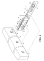
Fig. 4 shows the position relationship between the slide assembly and the installed member; -
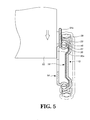
Fig. 5 shows a cross sectional view of the position relationship between the first mount of the installed member and the slide assembly, and -
Fig. 6 is a cross sectional view to show that the installed member is installed to the slide assembly of the present invention. - Referring to
Figs. 1 and2 , the slide assembly of the present invention comprises anouter rail 10, anintermediate rail 12, aninner rail 14 and at least one inner ball bearingset 16 located between theouter rail 10 and theintermediate rail 12, and aball bearing retainer 18 located between theintermediate rail 12 and theinner rail 14. - The
outer rail 10 is installed and positioned to a rack. - The
intermediate rail 12 is slidably connected to theouter rail 10 and has afirst wall 20, asecond wall 22 located corresponding to thefirst wall 20, and athird wall 24 connected to the first andsecond walls first wall 20 has afirst bearing face 26a. Preferably, thefirst wall 20 of theintermediate rail 12 has afirst notch 28 and thesecond wall 22 has asecond bearing face 26b which is located corresponding to thefirst notch 28 of thefirst wall 20. When theintermediate wall 12 is used, it is able to be used in both left and right sides. - The
inner rail 14 has atop wall 30, abottom wall 32 located corresponding to thetop wall 30, and aside wall 34 connected to the top andbottom walls top wall 30 of theinner rail 14 is located corresponding to thefirst bearing face 26a of thefirst wall 20 of theintermediate rail 12. Thebottom wall 32 of theinner rail 14 is located corresponding to thesecond bearing face 26b of thesecond wall 22 of theintermediate rail 12. In a preferable embodiment, thetop wall 30 of theinner rail 14 has afirst slot 36a, asecond slot 36b and athird slot 36c located between the first andsecond slots third slots side wall 34 of theinner rail 14. Preferably, theinner rail 14 has an engagingmember 37 which is able to be bent and returned relative to theinner rail 14, and the engagingmember 37 is located corresponding to one of the first, second andthird slots - The
ball bearing retainer 18, as shown inFig. 3 , has anupper member 38, abottom member 40 located corresponding to theupper member 38, and aconnection member 42 connected to the upper andbottom members ball bearing retainer 18 has a length, and theupper member 38 has a plurality of spaced upper retainingsections 44 located lengthwise along theball bearing retainer 18. Each of theupper retaining sections 44 at least has anupper ball bearing 46, and a distance L1 is defined between any adjacentupper retaining sections 44. Thebottom member 40 has a length corresponding to that of theupper member 38 and has a plurality of spacedbottom retaining sections 48. Each of thebottom retaining sections 48 along thebottom member 40 has a plurality ofbottom ball bearings 50. Theupper ball bearings 46 are located between thetop wall 30 of theinner rail 14 and thefirst bearing face 26a of theintermediate rail 12. Thebottom ball bearings 50 are located between thebottom wall 32 of theinner rail 14 and thesecond bearing face 26b of theintermediate rail 12. - As shown in
Fig. 4 , the slide assembly is provided with an installedmember 52 such as a chassis, the installedmember 52 at least includes afirst mount 54a, asecond mount 54b and athird mount 54c located between the first andsecond mounts first mount 54a of the installedmember 52 is smaller than the distance L1 between any adjacentupper retaining sections 44. The maximum diameter usually refers to the diameter of the circular head of the mount so that thefirst mount 54a can be inserted into and engaged with thefirst slot 36a of theinner rail 14 without being interfered by theball bearing retainer 18. Thesecond mount 54b can be inserted into and engaged with thesecond slot 36b of theinner rail 14 without being interfered by theball bearing retainer 18 by using the engagingmember 37. Thethird mount 54c can be inserted into and engaged with thethird slot 36c of theinner rail 14. -
Figs. 5 and6 show the engagement of the installedmember 52 with theinner rail 14. When theinner rail 14 is pulled out relative to theintermediate rail 12 to an extension position, thefirst slot 36a of theinner rail 14 is located corresponding to thefirst notch 28 of thefirst wall 20 of theintermediate rail 12. Theball bearing retainer 18 is moved to make thefirst notch 28 of theintermediate rail 12 and thefirst slot 36a of theinner rail 14 be located between any two of theupper retaining sections 44, so that thefirst mount 54a of the installedmember 52 extends through thefirst notch 28 of theintermediate rail 12 and yields theupper retaining sections 44 of theball bearing retainer 18 and enters into thefirst slot 36a of theinner rail 14 to be positioned. By this way, the installedmember 52 is connected with theinner rail 14, the upper andbottom members bottom ball bearings intermediate rails member 52 is connected to theinner rail 14 of the slide assembly. By the firm support of the inner andintermediate rails member 52 can be smoothly moved. - The present invention does not reduce the length of the
upper member 38 of theball bearing retainer 18, thanks to the distance between any two of theupper retaining sections 44. Thefirst mount 54a of the installedmember 52 can be engaged with theinner rail 14 without being interfered by theball bearing retainer 18. When the size of the chassis changes, theball bearing retainer 18 remains the same, only adjusting the distance between theball bearing retainer 18 and the chassis and using the distance between any two of theupper retaining sections 44, the chassis can be connected to the mounts. Besides, theball bearing retainer 18 separates the upper andbottom retaining sections intermediate rail 12, theinner rail 14 and theball bearing retainer 18 reinforces the support to the installedmember 52 and allows different sizes of the chasses to be connected to the slide assembly. The installedmember 52 can also be quickly installed to the slide assembly. - While we have shown and described the embodiment in accordance with the present invention, it should be clear to those skilled in the art that further embodiments may be made without departing from the scope of the present invention.
Claims (3)
- A slide assembly with quick-mount system, comprising:an outer rail (10);an intermediate rail (12) slidably connected to the outer rail (10) and having a first wall (20), a second wall (22) located corresponding to the first wall (20), and a third wall (24) connected to the first and second walls (20, 22), the first wall (20) having a first bearing face (26a) and a first notch (28), the second wall (22) having a second bearing face (26b);at least one inner ball bearing set (16) located between the outer rail (10) and the intermediate rail (12);an inner rail (14) having a top wall (30), a bottom wall (32) located corresponding to the top wall (30), and a side wall (34) connected to the top and bottom walls (30, 32), the top wall (30) of the inner rail (14) located corresponding to the first bearing face (26a) of the first wall (20) of the intermediate rail (12), the bottom wall (32) of the inner rail (14) located corresponding to the second bearing face (26b) of the second wall (22) of the intermediate rail (12), the top wall (30) of the inner rail (14) having a first slot (36a) and a second slot (36b), each of the first and second slots (36a, 36b) extending to a portion of the side wall (34) of the inner rail (14);an installed member (52) at least having a first mount (54a) and a second mount (54b);a ball bearing retainer (18) having an upper member (38), a bottom member (40) located corresponding to the upper member (38), and a connection member (42) connected to the upper and bottom members (38, 40), the ball bearing retainer (18) having a length, the upper member (38) having a plurality of spaced upper retaining sections (44) located lengthwise along the ball bearing retainer (18), each of the upper retaining sections (44) at least having an upper ball bearing (46), a distance between any adjacent upper retaining sections (44) being larger than a maximum diameter of the first mount (54a) of the installed member (52), the bottom member (40) having a length corresponding to that of the upper member (38) and having a plurality of spaced bottom retaining sections (48), a plurality of bottom ball bearings (50) connected to each of the bottom retaining sections (48) located along the bottom member (40), the upper ball bearings (46) located between the top wall (30) of the inner rail (14) and the first bearing face (26a) of the intermediate rail (12), the bottom ball bearings (50) located between the bottom wall (32) of the inner rail (14) and the second bearing face (26b) of the intermediate rail (12), and
wherein when the inner rail (14) is pulled out relative to the intermediate rail (12) to an extension position, the first slot (36a) of the inner rail (14) is located corresponding to the first notch (28) of the first wall (20) of the intermediate rail (12) and is located between any two of the upper retaining sections (44) of the ball bearing retainer (18), so that the first mount (54a) of the installed member (52) extends through the first notch (28) of the intermediate rail (12) and yields the ball bearing retainer (18) and enters into the first slot (36a) of the inner rail (14) to be positioned. - The slide assembly as claimed in claim 1, wherein the inner rail (14) has a third slot (36c) which is located between the first and second slots (36a, 36b), the installed member (52) has a third mount (54c) located between the first and second mounts (54a, 54b), the third mount (54c) is inserted into the third slot (36c) of the inner rail (14) and positioned.
- The slide assembly as claimed in claim 1, wherein the second wall (22) of the intermediate rail (12) has a second notch (29) which is located corresponding to the first notch (28) of the first wall (20).
Priority Applications (1)
| Application Number | Priority Date | Filing Date | Title |
|---|---|---|---|
| PL11182197T PL2446779T3 (en) | 2010-11-02 | 2011-09-21 | Slide assembly with quick-mount system |
Applications Claiming Priority (1)
| Application Number | Priority Date | Filing Date | Title |
|---|---|---|---|
| US40918010P | 2010-11-02 | 2010-11-02 |
Publications (2)
| Publication Number | Publication Date |
|---|---|
| EP2446779A1 true EP2446779A1 (en) | 2012-05-02 |
| EP2446779B1 EP2446779B1 (en) | 2013-07-24 |
Family
ID=44674537
Family Applications (1)
| Application Number | Title | Priority Date | Filing Date |
|---|---|---|---|
| EP11182197.1A Active EP2446779B1 (en) | 2010-11-02 | 2011-09-21 | Slide assembly with quick-mount system |
Country Status (7)
| Country | Link |
|---|---|
| US (1) | US8403433B2 (en) |
| EP (1) | EP2446779B1 (en) |
| JP (1) | JP3172302U (en) |
| CN (1) | CN102450873B (en) |
| ES (1) | ES2429154T3 (en) |
| PL (1) | PL2446779T3 (en) |
| TW (1) | TWI437946B (en) |
Cited By (6)
| Publication number | Priority date | Publication date | Assignee | Title |
|---|---|---|---|---|
| EP3041328A1 (en) * | 2014-12-30 | 2016-07-06 | King Slide Works Co., Ltd. | Slide rail assembly |
| EP3057386A1 (en) * | 2015-02-13 | 2016-08-17 | King Slide Works Co., Ltd. | Slide rail assembly |
| EP3166374A3 (en) * | 2015-11-04 | 2017-05-17 | King Slide Works Co., Ltd. | Slide rail assembly |
| EP3323314A1 (en) * | 2016-11-22 | 2018-05-23 | King Slide Works Co., Ltd. | Slide assembly with quick-mount system |
| EP3419397A1 (en) * | 2017-06-20 | 2018-12-26 | King Slide Works Co., Ltd. | Slide rail assembly |
| CN109152271A (en) * | 2017-06-27 | 2019-01-04 | 川湖科技股份有限公司 | Sliding rail assembly |
Families Citing this family (26)
| Publication number | Priority date | Publication date | Assignee | Title |
|---|---|---|---|---|
| US8528999B2 (en) * | 2011-09-06 | 2013-09-10 | King Slide Works Co., Ltd. | Slide assembly with positioning device |
| CN103653891B (en) * | 2012-08-31 | 2016-04-20 | 川湖科技股份有限公司 | Slide rail assembly and self-opening and closing slide rail assembly |
| CN104302146B (en) * | 2013-07-16 | 2019-05-10 | 伊顿制造(格拉斯哥)有限合伙莫尔日分支机构 | Horizontal slide rail component and component pair |
| USD733531S1 (en) * | 2013-09-26 | 2015-07-07 | Innovation First, Inc. | Bracket |
| TWI554233B (en) * | 2013-12-27 | 2016-10-21 | 川湖科技股份有限公司 | Slide assembly |
| CN104757797B (en) * | 2014-01-07 | 2017-03-01 | 川湖科技股份有限公司 | Sliding rail assembly |
| US9247814B2 (en) | 2014-03-31 | 2016-02-02 | King Slide Works Co., Ltd. | Slide rail assembly |
| TW201607417A (en) * | 2014-08-05 | 2016-02-16 | Martas Prec Slide Co Ltd | Slim-type sliding rail for server cabinet |
| US9642279B2 (en) * | 2015-03-12 | 2017-05-02 | King Slide Works Co., Ltd. | Rail mounting structure |
| US9731364B2 (en) * | 2015-03-31 | 2017-08-15 | Chin-Chin Chang | Three part slide and locking mechanism for use with a table saw |
| CN106320104A (en) * | 2015-07-08 | 2017-01-11 | 佛山市合阁钢构集成房屋有限公司 | Super-heavy load super-long drawer type guide rail |
| TWI559872B (en) * | 2015-07-09 | 2016-12-01 | King Slide Works Co Ltd | Rail mounting mechanism |
| TWI578882B (en) * | 2015-07-15 | 2017-04-11 | King Slide Works Co Ltd | Slide rail assembly |
| DE202015106016U1 (en) * | 2015-11-09 | 2017-02-13 | Accuride International Gmbh | Crash locking |
| CN106714499A (en) * | 2015-11-17 | 2017-05-24 | 川湖科技股份有限公司 | Sliding rail assembly |
| TWI568381B (en) * | 2015-12-21 | 2017-02-01 | 川湖科技股份有限公司 | Slide rail assembly and guiding mechanism thereof |
| US10117352B2 (en) * | 2016-01-06 | 2018-10-30 | King Slide Works Co., Ltd. | Slide rail assembly |
| CN107007050B (en) * | 2016-01-11 | 2020-12-01 | 川湖科技股份有限公司 | Slide rail assembly |
| CN107484382B (en) * | 2016-06-07 | 2020-07-28 | 川湖科技股份有限公司 | Sliding rail assembly |
| US9967996B2 (en) * | 2016-09-26 | 2018-05-08 | Super Micro Computer Inc. | Server chassis |
| US10213017B2 (en) * | 2016-10-05 | 2019-02-26 | King Slide Works Co., Ltd. | Slide rail assembly |
| CN107960763B (en) * | 2016-10-18 | 2020-01-14 | 川湖科技股份有限公司 | Sliding rail assembly |
| CN107951237B (en) * | 2016-10-18 | 2020-01-14 | 川湖科技股份有限公司 | Sliding rail assembly |
| EP3440958B1 (en) * | 2017-07-28 | 2021-03-03 | Varidesk, LLC | Motorized adjustable height table |
| TWI658803B (en) * | 2017-12-28 | 2019-05-11 | 川湖科技股份有限公司 | Slide rail assembly and rail kit thereof |
| US12363850B2 (en) * | 2023-02-17 | 2025-07-15 | Dell Products L.P. | Tray with translation features supporting on-rack service |
Citations (3)
| Publication number | Priority date | Publication date | Assignee | Title |
|---|---|---|---|---|
| US6209979B1 (en) | 2000-02-22 | 2001-04-03 | General Devices Co., Ltd. | Telescoping slide with quick-mount system |
| US20060279187A1 (en) * | 2005-06-10 | 2006-12-14 | Central Industrial Supply Company | Detent pin bearing retainer lock for a drawer slide |
| US20070127856A1 (en) | 2005-09-02 | 2007-06-07 | John Young | Drop-in ball bearing slide assembly |
Family Cites Families (13)
| Publication number | Priority date | Publication date | Assignee | Title |
|---|---|---|---|---|
| US4331369A (en) * | 1980-05-22 | 1982-05-25 | Scientific Micro Systems, Inc. | Chassis integrated slide |
| US6948691B2 (en) * | 2000-03-17 | 2005-09-27 | Jonathan Manufacturing Corporation | Computer server mounting apparatus |
| US6588866B2 (en) * | 2001-04-27 | 2003-07-08 | Intel Corporation | Slide rail attachment |
| US6938967B2 (en) * | 2001-12-12 | 2005-09-06 | Pentair Electronic Packaging Co. | Telescoping slide assembly |
| CN2536741Y (en) * | 2002-03-28 | 2003-02-19 | 震营企业股份有限公司 | Three-stage ball slide rail device |
| WO2004107912A2 (en) * | 2003-05-30 | 2004-12-16 | Central Industrial Supply Company (A Texas Corporation) | Cam lock with torsion spring for a drawer slide |
| US7382623B2 (en) * | 2003-06-11 | 2008-06-03 | Dell Products L.P. | Method and system for coupling a chassis to a rail |
| US7604307B2 (en) * | 2003-10-24 | 2009-10-20 | General Devices Co., Inc. | Telescoping slide assembly with quick-mount keyhole lock system |
| CN2655738Y (en) * | 2003-11-11 | 2004-11-17 | 东莞市石龙万通实业有限公司 | A push-type adjustable telescopic slide rail |
| US7481504B2 (en) * | 2005-11-23 | 2009-01-27 | King Slide Works Co., Ltd. | Mount latch structure for a telescoping slide |
| US7513581B1 (en) * | 2007-06-07 | 2009-04-07 | Central Industrial Supply Company | Chassis lock for a drawer slide |
| CN101587368B (en) * | 2008-05-23 | 2011-11-09 | 鸿富锦精密工业(深圳)有限公司 | Sliding rail device |
| CN101721057A (en) * | 2008-10-22 | 2010-06-09 | 大讯科技股份有限公司 | Ultrathin sliding rail |
-
2011
- 2011-09-21 ES ES11182197T patent/ES2429154T3/en active Active
- 2011-09-21 PL PL11182197T patent/PL2446779T3/en unknown
- 2011-09-21 US US13/238,068 patent/US8403433B2/en active Active
- 2011-09-21 EP EP11182197.1A patent/EP2446779B1/en active Active
- 2011-09-22 JP JP2011005537U patent/JP3172302U/en not_active Expired - Lifetime
- 2011-10-07 TW TW100136680A patent/TWI437946B/en active
- 2011-10-26 CN CN2011103546305A patent/CN102450873B/en active Active
Patent Citations (3)
| Publication number | Priority date | Publication date | Assignee | Title |
|---|---|---|---|---|
| US6209979B1 (en) | 2000-02-22 | 2001-04-03 | General Devices Co., Ltd. | Telescoping slide with quick-mount system |
| US20060279187A1 (en) * | 2005-06-10 | 2006-12-14 | Central Industrial Supply Company | Detent pin bearing retainer lock for a drawer slide |
| US20070127856A1 (en) | 2005-09-02 | 2007-06-07 | John Young | Drop-in ball bearing slide assembly |
Cited By (7)
| Publication number | Priority date | Publication date | Assignee | Title |
|---|---|---|---|---|
| EP3041328A1 (en) * | 2014-12-30 | 2016-07-06 | King Slide Works Co., Ltd. | Slide rail assembly |
| EP3057386A1 (en) * | 2015-02-13 | 2016-08-17 | King Slide Works Co., Ltd. | Slide rail assembly |
| EP3166374A3 (en) * | 2015-11-04 | 2017-05-17 | King Slide Works Co., Ltd. | Slide rail assembly |
| EP3323314A1 (en) * | 2016-11-22 | 2018-05-23 | King Slide Works Co., Ltd. | Slide assembly with quick-mount system |
| EP3419397A1 (en) * | 2017-06-20 | 2018-12-26 | King Slide Works Co., Ltd. | Slide rail assembly |
| CN109152271A (en) * | 2017-06-27 | 2019-01-04 | 川湖科技股份有限公司 | Sliding rail assembly |
| CN109152271B (en) * | 2017-06-27 | 2020-10-16 | 川湖科技股份有限公司 | Slide rail assembly |
Also Published As
| Publication number | Publication date |
|---|---|
| TW201233294A (en) | 2012-08-01 |
| JP3172302U (en) | 2011-12-15 |
| TWI437946B (en) | 2014-05-11 |
| US20120106880A1 (en) | 2012-05-03 |
| US8403433B2 (en) | 2013-03-26 |
| CN102450873B (en) | 2013-10-09 |
| ES2429154T3 (en) | 2013-11-13 |
| PL2446779T3 (en) | 2013-12-31 |
| EP2446779B1 (en) | 2013-07-24 |
| CN102450873A (en) | 2012-05-16 |
Similar Documents
| Publication | Publication Date | Title |
|---|---|---|
| EP2446779B1 (en) | Slide assembly with quick-mount system | |
| EP2438835B1 (en) | Reinforcement device for slide assembly | |
| EP3258755B1 (en) | Rack system | |
| EP3197252A1 (en) | Slide rail assembly and guiding mechanism thereof | |
| US9237671B2 (en) | Slide rail assembly for rack system | |
| US8528999B2 (en) | Slide assembly with positioning device | |
| US9560786B2 (en) | Slide rail assembly and slide rail assembly pair | |
| EP2283744B1 (en) | Drawer assembly | |
| EP2438834A1 (en) | Reinforcement and adjustment device for slide assembly | |
| US8297723B2 (en) | Interlock device for slide assembly | |
| US9258923B2 (en) | Adjustable bracket assembly and slide assembly | |
| EP3457826B1 (en) | Rack system and slide rail assembly thereof | |
| CN104873012A (en) | Slide Rail And Equipment Mounting Rack | |
| EP2560470A2 (en) | Slide assembly with positioning device | |
| EP3273757A1 (en) | Slide rail assembly for rack system | |
| EP2417873A1 (en) | Slide assembly | |
| US8672431B2 (en) | Slide rail assembly | |
| CN102883578A (en) | Slide rail locking device | |
| KR20160065725A (en) | Fixing apparatus for sliding rail | |
| EP2893838B1 (en) | Slide assembly comprising an adjustable bracket | |
| JP3196235U (en) | Slide guide rail system | |
| EP2246632A1 (en) | Support for extractable baking trays and/or baking grids | |
| US20160051050A1 (en) | Side mounted drawer slide | |
| US9967996B2 (en) | Server chassis | |
| EP3167758B1 (en) | Drawer sidewall assembly |
Legal Events
| Date | Code | Title | Description |
|---|---|---|---|
| PUAI | Public reference made under article 153(3) epc to a published international application that has entered the european phase |
Free format text: ORIGINAL CODE: 0009012 |
|
| AK | Designated contracting states |
Kind code of ref document: A1 Designated state(s): AL AT BE BG CH CY CZ DE DK EE ES FI FR GB GR HR HU IE IS IT LI LT LU LV MC MK MT NL NO PL PT RO RS SE SI SK SM TR |
|
| AX | Request for extension of the european patent |
Extension state: BA ME |
|
| RIN1 | Information on inventor provided before grant (corrected) |
Inventor name: YANG, SHUN-HO Inventor name: WANG, CHUN-CHIANG Inventor name: CHEN, KEN-CHING |
|
| 17P | Request for examination filed |
Effective date: 20120420 |
|
| RIC1 | Information provided on ipc code assigned before grant |
Ipc: A47B 88/00 20060101ALI20120518BHEP Ipc: H05K 7/18 20060101ALI20120518BHEP Ipc: A47B 88/04 20060101AFI20120518BHEP |
|
| GRAP | Despatch of communication of intention to grant a patent |
Free format text: ORIGINAL CODE: EPIDOSNIGR1 |
|
| GRAS | Grant fee paid |
Free format text: ORIGINAL CODE: EPIDOSNIGR3 |
|
| GRAA | (expected) grant |
Free format text: ORIGINAL CODE: 0009210 |
|
| AK | Designated contracting states |
Kind code of ref document: B1 Designated state(s): AL AT BE BG CH CY CZ DE DK EE ES FI FR GB GR HR HU IE IS IT LI LT LU LV MC MK MT NL NO PL PT RO RS SE SI SK SM TR |
|
| REG | Reference to a national code |
Ref country code: GB Ref legal event code: FG4D |
|
| REG | Reference to a national code |
Ref country code: CH Ref legal event code: EP |
|
| REG | Reference to a national code |
Ref country code: AT Ref legal event code: REF Ref document number: 622885 Country of ref document: AT Kind code of ref document: T Effective date: 20130815 |
|
| REG | Reference to a national code |
Ref country code: IE Ref legal event code: FG4D |
|
| REG | Reference to a national code |
Ref country code: DE Ref legal event code: R096 Ref document number: 602011002435 Country of ref document: DE Effective date: 20130919 |
|
| REG | Reference to a national code |
Ref country code: ES Ref legal event code: FG2A Ref document number: 2429154 Country of ref document: ES Kind code of ref document: T3 Effective date: 20131113 |
|
| REG | Reference to a national code |
Ref country code: NL Ref legal event code: T3 |
|
| REG | Reference to a national code |
Ref country code: LT Ref legal event code: MG4D |
|
| REG | Reference to a national code |
Ref country code: PL Ref legal event code: T3 |
|
| PG25 | Lapsed in a contracting state [announced via postgrant information from national office to epo] |
Ref country code: LT Free format text: LAPSE BECAUSE OF FAILURE TO SUBMIT A TRANSLATION OF THE DESCRIPTION OR TO PAY THE FEE WITHIN THE PRESCRIBED TIME-LIMIT Effective date: 20130724 Ref country code: SE Free format text: LAPSE BECAUSE OF FAILURE TO SUBMIT A TRANSLATION OF THE DESCRIPTION OR TO PAY THE FEE WITHIN THE PRESCRIBED TIME-LIMIT Effective date: 20130724 Ref country code: IS Free format text: LAPSE BECAUSE OF FAILURE TO SUBMIT A TRANSLATION OF THE DESCRIPTION OR TO PAY THE FEE WITHIN THE PRESCRIBED TIME-LIMIT Effective date: 20131124 Ref country code: PT Free format text: LAPSE BECAUSE OF FAILURE TO SUBMIT A TRANSLATION OF THE DESCRIPTION OR TO PAY THE FEE WITHIN THE PRESCRIBED TIME-LIMIT Effective date: 20131125 Ref country code: CY Free format text: LAPSE BECAUSE OF FAILURE TO SUBMIT A TRANSLATION OF THE DESCRIPTION OR TO PAY THE FEE WITHIN THE PRESCRIBED TIME-LIMIT Effective date: 20130821 Ref country code: BE Free format text: LAPSE BECAUSE OF FAILURE TO SUBMIT A TRANSLATION OF THE DESCRIPTION OR TO PAY THE FEE WITHIN THE PRESCRIBED TIME-LIMIT Effective date: 20130724 Ref country code: NO Free format text: LAPSE BECAUSE OF FAILURE TO SUBMIT A TRANSLATION OF THE DESCRIPTION OR TO PAY THE FEE WITHIN THE PRESCRIBED TIME-LIMIT Effective date: 20131024 Ref country code: HR Free format text: LAPSE BECAUSE OF FAILURE TO SUBMIT A TRANSLATION OF THE DESCRIPTION OR TO PAY THE FEE WITHIN THE PRESCRIBED TIME-LIMIT Effective date: 20130724 |
|
| PG25 | Lapsed in a contracting state [announced via postgrant information from national office to epo] |
Ref country code: LV Free format text: LAPSE BECAUSE OF FAILURE TO SUBMIT A TRANSLATION OF THE DESCRIPTION OR TO PAY THE FEE WITHIN THE PRESCRIBED TIME-LIMIT Effective date: 20130724 Ref country code: SI Free format text: LAPSE BECAUSE OF FAILURE TO SUBMIT A TRANSLATION OF THE DESCRIPTION OR TO PAY THE FEE WITHIN THE PRESCRIBED TIME-LIMIT Effective date: 20130724 Ref country code: FI Free format text: LAPSE BECAUSE OF FAILURE TO SUBMIT A TRANSLATION OF THE DESCRIPTION OR TO PAY THE FEE WITHIN THE PRESCRIBED TIME-LIMIT Effective date: 20130724 |
|
| PG25 | Lapsed in a contracting state [announced via postgrant information from national office to epo] |
Ref country code: CY Free format text: LAPSE BECAUSE OF FAILURE TO SUBMIT A TRANSLATION OF THE DESCRIPTION OR TO PAY THE FEE WITHIN THE PRESCRIBED TIME-LIMIT Effective date: 20130724 |
|
| PG25 | Lapsed in a contracting state [announced via postgrant information from national office to epo] |
Ref country code: MC Free format text: LAPSE BECAUSE OF FAILURE TO SUBMIT A TRANSLATION OF THE DESCRIPTION OR TO PAY THE FEE WITHIN THE PRESCRIBED TIME-LIMIT Effective date: 20130724 Ref country code: DK Free format text: LAPSE BECAUSE OF FAILURE TO SUBMIT A TRANSLATION OF THE DESCRIPTION OR TO PAY THE FEE WITHIN THE PRESCRIBED TIME-LIMIT Effective date: 20130724 Ref country code: RO Free format text: LAPSE BECAUSE OF FAILURE TO SUBMIT A TRANSLATION OF THE DESCRIPTION OR TO PAY THE FEE WITHIN THE PRESCRIBED TIME-LIMIT Effective date: 20130724 Ref country code: EE Free format text: LAPSE BECAUSE OF FAILURE TO SUBMIT A TRANSLATION OF THE DESCRIPTION OR TO PAY THE FEE WITHIN THE PRESCRIBED TIME-LIMIT Effective date: 20130724 Ref country code: SK Free format text: LAPSE BECAUSE OF FAILURE TO SUBMIT A TRANSLATION OF THE DESCRIPTION OR TO PAY THE FEE WITHIN THE PRESCRIBED TIME-LIMIT Effective date: 20130724 |
|
| PG25 | Lapsed in a contracting state [announced via postgrant information from national office to epo] |
Ref country code: IT Free format text: LAPSE BECAUSE OF FAILURE TO SUBMIT A TRANSLATION OF THE DESCRIPTION OR TO PAY THE FEE WITHIN THE PRESCRIBED TIME-LIMIT Effective date: 20130724 |
|
| PLBE | No opposition filed within time limit |
Free format text: ORIGINAL CODE: 0009261 |
|
| STAA | Information on the status of an ep patent application or granted ep patent |
Free format text: STATUS: NO OPPOSITION FILED WITHIN TIME LIMIT |
|
| REG | Reference to a national code |
Ref country code: FR Ref legal event code: ST Effective date: 20140530 |
|
| 26N | No opposition filed |
Effective date: 20140425 |
|
| REG | Reference to a national code |
Ref country code: DE Ref legal event code: R097 Ref document number: 602011002435 Country of ref document: DE Effective date: 20140425 |
|
| PG25 | Lapsed in a contracting state [announced via postgrant information from national office to epo] |
Ref country code: FR Free format text: LAPSE BECAUSE OF NON-PAYMENT OF DUE FEES Effective date: 20130930 |
|
| REG | Reference to a national code |
Ref country code: CH Ref legal event code: PL |
|
| PG25 | Lapsed in a contracting state [announced via postgrant information from national office to epo] |
Ref country code: SM Free format text: LAPSE BECAUSE OF FAILURE TO SUBMIT A TRANSLATION OF THE DESCRIPTION OR TO PAY THE FEE WITHIN THE PRESCRIBED TIME-LIMIT Effective date: 20130724 |
|
| PG25 | Lapsed in a contracting state [announced via postgrant information from national office to epo] |
Ref country code: TR Free format text: LAPSE BECAUSE OF FAILURE TO SUBMIT A TRANSLATION OF THE DESCRIPTION OR TO PAY THE FEE WITHIN THE PRESCRIBED TIME-LIMIT Effective date: 20130724 Ref country code: MT Free format text: LAPSE BECAUSE OF FAILURE TO SUBMIT A TRANSLATION OF THE DESCRIPTION OR TO PAY THE FEE WITHIN THE PRESCRIBED TIME-LIMIT Effective date: 20130724 |
|
| PG25 | Lapsed in a contracting state [announced via postgrant information from national office to epo] |
Ref country code: LU Free format text: LAPSE BECAUSE OF NON-PAYMENT OF DUE FEES Effective date: 20130921 Ref country code: BG Free format text: LAPSE BECAUSE OF FAILURE TO SUBMIT A TRANSLATION OF THE DESCRIPTION OR TO PAY THE FEE WITHIN THE PRESCRIBED TIME-LIMIT Effective date: 20130724 Ref country code: HU Free format text: LAPSE BECAUSE OF FAILURE TO SUBMIT A TRANSLATION OF THE DESCRIPTION OR TO PAY THE FEE WITHIN THE PRESCRIBED TIME-LIMIT; INVALID AB INITIO Effective date: 20110921 Ref country code: RS Free format text: LAPSE BECAUSE OF FAILURE TO SUBMIT A TRANSLATION OF THE DESCRIPTION OR TO PAY THE FEE WITHIN THE PRESCRIBED TIME-LIMIT Effective date: 20131024 Ref country code: LI Free format text: LAPSE BECAUSE OF NON-PAYMENT OF DUE FEES Effective date: 20140930 Ref country code: MK Free format text: LAPSE BECAUSE OF FAILURE TO SUBMIT A TRANSLATION OF THE DESCRIPTION OR TO PAY THE FEE WITHIN THE PRESCRIBED TIME-LIMIT Effective date: 20130724 Ref country code: CH Free format text: LAPSE BECAUSE OF NON-PAYMENT OF DUE FEES Effective date: 20140930 |
|
| PG25 | Lapsed in a contracting state [announced via postgrant information from national office to epo] |
Ref country code: GR Free format text: LAPSE BECAUSE OF NON-PAYMENT OF DUE FEES Effective date: 20130724 |
|
| REG | Reference to a national code |
Ref country code: DE Ref legal event code: R079 Ref document number: 602011002435 Country of ref document: DE Free format text: PREVIOUS MAIN CLASS: A47B0088040000 Ipc: A47B0088400000 |
|
| PG25 | Lapsed in a contracting state [announced via postgrant information from national office to epo] |
Ref country code: AL Free format text: LAPSE BECAUSE OF FAILURE TO SUBMIT A TRANSLATION OF THE DESCRIPTION OR TO PAY THE FEE WITHIN THE PRESCRIBED TIME-LIMIT Effective date: 20130724 |
|
| PGFP | Annual fee paid to national office [announced via postgrant information from national office to epo] |
Ref country code: NL Payment date: 20250714 Year of fee payment: 15 |
|
| PGFP | Annual fee paid to national office [announced via postgrant information from national office to epo] |
Ref country code: DE Payment date: 20250714 Year of fee payment: 15 |
|
| PGFP | Annual fee paid to national office [announced via postgrant information from national office to epo] |
Ref country code: PL Payment date: 20250708 Year of fee payment: 15 |
|
| PGFP | Annual fee paid to national office [announced via postgrant information from national office to epo] |
Ref country code: GB Payment date: 20250708 Year of fee payment: 15 |
|
| PGFP | Annual fee paid to national office [announced via postgrant information from national office to epo] |
Ref country code: AT Payment date: 20250827 Year of fee payment: 15 |
|
| PGFP | Annual fee paid to national office [announced via postgrant information from national office to epo] |
Ref country code: CZ Payment date: 20250911 Year of fee payment: 15 Ref country code: IE Payment date: 20250715 Year of fee payment: 15 |
|
| PGFP | Annual fee paid to national office [announced via postgrant information from national office to epo] |
Ref country code: ES Payment date: 20251013 Year of fee payment: 15 |