EP2445552B1 - Administering device having a priming function - Google Patents
Administering device having a priming function Download PDFInfo
- Publication number
- EP2445552B1 EP2445552B1 EP09779934.0A EP09779934A EP2445552B1 EP 2445552 B1 EP2445552 B1 EP 2445552B1 EP 09779934 A EP09779934 A EP 09779934A EP 2445552 B1 EP2445552 B1 EP 2445552B1
- Authority
- EP
- European Patent Office
- Prior art keywords
- dosing
- reservoir
- dose
- administration device
- housing
- Prior art date
- Legal status (The legal status is an assumption and is not a legal conclusion. Google has not performed a legal analysis and makes no representation as to the accuracy of the status listed.)
- Active
Links
Images


Classifications
-
- A—HUMAN NECESSITIES
- A61—MEDICAL OR VETERINARY SCIENCE; HYGIENE
- A61M—DEVICES FOR INTRODUCING MEDIA INTO, OR ONTO, THE BODY; DEVICES FOR TRANSDUCING BODY MEDIA OR FOR TAKING MEDIA FROM THE BODY; DEVICES FOR PRODUCING OR ENDING SLEEP OR STUPOR
- A61M5/00—Devices for bringing media into the body in a subcutaneous, intra-vascular or intramuscular way; Accessories therefor, e.g. filling or cleaning devices, arm-rests
- A61M5/178—Syringes
- A61M5/31—Details
- A61M5/315—Pistons; Piston-rods; Guiding, blocking or restricting the movement of the rod or piston; Appliances on the rod for facilitating dosing ; Dosing mechanisms
- A61M5/31533—Dosing mechanisms, i.e. setting a dose
- A61M5/31545—Setting modes for dosing
- A61M5/31548—Mechanically operated dose setting member
- A61M5/3155—Mechanically operated dose setting member by rotational movement of dose setting member, e.g. during setting or filling of a syringe
- A61M5/31553—Mechanically operated dose setting member by rotational movement of dose setting member, e.g. during setting or filling of a syringe without axial movement of dose setting member
-
- A—HUMAN NECESSITIES
- A61—MEDICAL OR VETERINARY SCIENCE; HYGIENE
- A61M—DEVICES FOR INTRODUCING MEDIA INTO, OR ONTO, THE BODY; DEVICES FOR TRANSDUCING BODY MEDIA OR FOR TAKING MEDIA FROM THE BODY; DEVICES FOR PRODUCING OR ENDING SLEEP OR STUPOR
- A61M5/00—Devices for bringing media into the body in a subcutaneous, intra-vascular or intramuscular way; Accessories therefor, e.g. filling or cleaning devices, arm-rests
- A61M5/178—Syringes
- A61M5/31—Details
- A61M5/3146—Priming, e.g. purging, reducing backlash or clearance
-
- A—HUMAN NECESSITIES
- A61—MEDICAL OR VETERINARY SCIENCE; HYGIENE
- A61M—DEVICES FOR INTRODUCING MEDIA INTO, OR ONTO, THE BODY; DEVICES FOR TRANSDUCING BODY MEDIA OR FOR TAKING MEDIA FROM THE BODY; DEVICES FOR PRODUCING OR ENDING SLEEP OR STUPOR
- A61M5/00—Devices for bringing media into the body in a subcutaneous, intra-vascular or intramuscular way; Accessories therefor, e.g. filling or cleaning devices, arm-rests
- A61M5/178—Syringes
- A61M5/31—Details
- A61M5/315—Pistons; Piston-rods; Guiding, blocking or restricting the movement of the rod or piston; Appliances on the rod for facilitating dosing ; Dosing mechanisms
- A61M5/31533—Dosing mechanisms, i.e. setting a dose
- A61M5/31545—Setting modes for dosing
- A61M5/31548—Mechanically operated dose setting member
- A61M5/3156—Mechanically operated dose setting member using volume steps only adjustable in discrete intervals, i.e. individually distinct intervals
-
- A—HUMAN NECESSITIES
- A61—MEDICAL OR VETERINARY SCIENCE; HYGIENE
- A61M—DEVICES FOR INTRODUCING MEDIA INTO, OR ONTO, THE BODY; DEVICES FOR TRANSDUCING BODY MEDIA OR FOR TAKING MEDIA FROM THE BODY; DEVICES FOR PRODUCING OR ENDING SLEEP OR STUPOR
- A61M5/00—Devices for bringing media into the body in a subcutaneous, intra-vascular or intramuscular way; Accessories therefor, e.g. filling or cleaning devices, arm-rests
- A61M5/178—Syringes
- A61M5/31—Details
- A61M5/315—Pistons; Piston-rods; Guiding, blocking or restricting the movement of the rod or piston; Appliances on the rod for facilitating dosing ; Dosing mechanisms
- A61M5/31565—Administration mechanisms, i.e. constructional features, modes of administering a dose
- A61M5/31576—Constructional features or modes of drive mechanisms for piston rods
- A61M5/31578—Constructional features or modes of drive mechanisms for piston rods based on axial translation, i.e. components directly operatively associated and axially moved with plunger rod
- A61M5/3158—Constructional features or modes of drive mechanisms for piston rods based on axial translation, i.e. components directly operatively associated and axially moved with plunger rod performed by axially moving actuator operated by user, e.g. an injection button
-
- A—HUMAN NECESSITIES
- A61—MEDICAL OR VETERINARY SCIENCE; HYGIENE
- A61M—DEVICES FOR INTRODUCING MEDIA INTO, OR ONTO, THE BODY; DEVICES FOR TRANSDUCING BODY MEDIA OR FOR TAKING MEDIA FROM THE BODY; DEVICES FOR PRODUCING OR ENDING SLEEP OR STUPOR
- A61M5/00—Devices for bringing media into the body in a subcutaneous, intra-vascular or intramuscular way; Accessories therefor, e.g. filling or cleaning devices, arm-rests
- A61M5/178—Syringes
- A61M5/31—Details
- A61M2005/3117—Means preventing contamination of the medicament compartment of a syringe
- A61M2005/3118—Means preventing contamination of the medicament compartment of a syringe via the distal end of a syringe, i.e. syringe end for mounting a needle cannula
-
- A—HUMAN NECESSITIES
- A61—MEDICAL OR VETERINARY SCIENCE; HYGIENE
- A61M—DEVICES FOR INTRODUCING MEDIA INTO, OR ONTO, THE BODY; DEVICES FOR TRANSDUCING BODY MEDIA OR FOR TAKING MEDIA FROM THE BODY; DEVICES FOR PRODUCING OR ENDING SLEEP OR STUPOR
- A61M5/00—Devices for bringing media into the body in a subcutaneous, intra-vascular or intramuscular way; Accessories therefor, e.g. filling or cleaning devices, arm-rests
- A61M5/178—Syringes
- A61M5/24—Ampoule syringes, i.e. syringes with needle for use in combination with replaceable ampoules or carpules, e.g. automatic
- A61M5/2455—Ampoule syringes, i.e. syringes with needle for use in combination with replaceable ampoules or carpules, e.g. automatic with sealing means to be broken or opened
- A61M5/2466—Ampoule syringes, i.e. syringes with needle for use in combination with replaceable ampoules or carpules, e.g. automatic with sealing means to be broken or opened by piercing without internal pressure increase
-
- A—HUMAN NECESSITIES
- A61—MEDICAL OR VETERINARY SCIENCE; HYGIENE
- A61M—DEVICES FOR INTRODUCING MEDIA INTO, OR ONTO, THE BODY; DEVICES FOR TRANSDUCING BODY MEDIA OR FOR TAKING MEDIA FROM THE BODY; DEVICES FOR PRODUCING OR ENDING SLEEP OR STUPOR
- A61M5/00—Devices for bringing media into the body in a subcutaneous, intra-vascular or intramuscular way; Accessories therefor, e.g. filling or cleaning devices, arm-rests
- A61M5/178—Syringes
- A61M5/31—Details
- A61M5/315—Pistons; Piston-rods; Guiding, blocking or restricting the movement of the rod or piston; Appliances on the rod for facilitating dosing ; Dosing mechanisms
- A61M5/31565—Administration mechanisms, i.e. constructional features, modes of administering a dose
- A61M5/31566—Means improving security or handling thereof
- A61M5/3157—Means providing feedback signals when administration is completed
-
- A—HUMAN NECESSITIES
- A61—MEDICAL OR VETERINARY SCIENCE; HYGIENE
- A61M—DEVICES FOR INTRODUCING MEDIA INTO, OR ONTO, THE BODY; DEVICES FOR TRANSDUCING BODY MEDIA OR FOR TAKING MEDIA FROM THE BODY; DEVICES FOR PRODUCING OR ENDING SLEEP OR STUPOR
- A61M5/00—Devices for bringing media into the body in a subcutaneous, intra-vascular or intramuscular way; Accessories therefor, e.g. filling or cleaning devices, arm-rests
- A61M5/178—Syringes
- A61M5/31—Details
- A61M5/315—Pistons; Piston-rods; Guiding, blocking or restricting the movement of the rod or piston; Appliances on the rod for facilitating dosing ; Dosing mechanisms
- A61M5/31565—Administration mechanisms, i.e. constructional features, modes of administering a dose
- A61M5/3159—Dose expelling manners
- A61M5/31591—Single dose, i.e. individually set dose administered only once from the same medicament reservoir, e.g. including single stroke limiting means
-
- A—HUMAN NECESSITIES
- A61—MEDICAL OR VETERINARY SCIENCE; HYGIENE
- A61M—DEVICES FOR INTRODUCING MEDIA INTO, OR ONTO, THE BODY; DEVICES FOR TRANSDUCING BODY MEDIA OR FOR TAKING MEDIA FROM THE BODY; DEVICES FOR PRODUCING OR ENDING SLEEP OR STUPOR
- A61M5/00—Devices for bringing media into the body in a subcutaneous, intra-vascular or intramuscular way; Accessories therefor, e.g. filling or cleaning devices, arm-rests
- A61M5/50—Devices for bringing media into the body in a subcutaneous, intra-vascular or intramuscular way; Accessories therefor, e.g. filling or cleaning devices, arm-rests having means for preventing re-use, or for indicating if defective, used, tampered with or unsterile
- A61M5/5013—Means for blocking the piston or the fluid passageway to prevent illegal refilling of a syringe
- A61M5/502—Means for blocking the piston or the fluid passageway to prevent illegal refilling of a syringe for blocking the piston
Definitions
- the invention relates to an administration device for a liquid medicament, which may in particular be a liquid formulation containing FSH or an FSH variant.
- liquid medicaments are not only liquids in the narrower sense, but also paste and gelatinous medicaments, as long as such medicaments can only be promoted comparable to a liquid.
- the administration device is preferably an injection device for administration by means of an infusing injection needle, preferably for a subcutaneous injection, but in principle may also be an injection device for needleless administration or, for example, also an inhalation device. Injection devices in the form of so-called Injetechnischspens are particularly preferred embodiments.
- Modern injection pens allow the exact dosage of the drug, individually by the patient himself.
- the increased flexibility through the free selection of the dose allows the use in therapies in which the patients administer the drug themselves, the so-called self-administration.
- high operational safety and a high ease of use are required.
- the devices are designed to prevent operating errors from home.
- One source of error is the inclusion of air in the drug reservoir. If this air is not removed before administration, there is a risk that not the drug in the set dose, but the drug is administered together with the trapped air according to the set dose.
- priming is left to the patient's discretion, who sets a small dose on a dosing device, holds the device up with the needle, and releases the set priming volume into the open air by operating the device.
- Other devices for example one from the EP 0 927 058 A1 known device, are specially with Priming mechanisms equipped, however, bring a considerable design effort and therefore significantly increased costs.
- the US 2003/0158523 A1 discloses an injection device comprising a housing in which a multi-chamber ampoule is received, and a metering and delivery member by means of which a powdered and a liquid component of the medicament can be mixed and the blended medicament can be administered.
- the metering and delivery member is rotatable about a longitudinal axis for adjustment of a dose to be administered and movable for mixing the medicament and dispensing the adjusted dose in the axial advancing direction.
- the metering and delivery member interacts with the housing such that it must perform a priming stroke after mixing and before setting the dose.
- VerFblockiereingriff is achieved by an axial priming stroke of the dosing and conveying member. After execution of the priming stroke, the metering and delivery member can be rotated relative to the housing again and thereby set the dose to be administered.
- the WO 00/62839 A2 describes an injection device with a dosing and conveying member, which is manually withdrawn after execution of a short priming stroke against the advancing direction. By retracting a Vermostechnischseingriff the metering and delivery member is released, so that this rotatable in the retracted position and thereby the dose to be administered is adjustable.
- the drug is therefore usually delivered in a preserved form in larger containers, from which the patients raise their administration device, ie can fill its reservoir with the preserved drug.
- the patient receives two containers, one with an unpreserved formulation and the other with the preservative, so that the patient can self-mix the preserved drug and store it for a prolonged period in the subsequently preserved condition.
- the preservative exerts on the preservative effect on the active ingredient, FSH or FSH variants, at most negative impact on the stability of the drug and also increases the price of the finished, preserved drug.
- the mounting or mixing of the delivery device from a sterile closed larger container containing a preserved or unpreserved formulation is cumbersome. In addition, it requires a dressing exactly the dose to be administered.
- the device should be particularly suitable for the administration of a liquid, non-preserved formulation containing FSH or an FSH variant.
- the invention relates to an administering device comprising a housing, a reservoir for a liquid medicament, a dosing member for adjusting a dose of medicament to be administered, and a conveyor having a delivery member for delivering the adjusted dose.
- the housing may directly form the reservoir if, for example, a syringe forms the housing or part of the housing.
- the reservoir can also be a container accommodated in the housing, preferably in the form of a carpule.
- the dosing member is movable relative to the housing for adjusting the dose. The movement which the dosing member makes in the selection of the dose and the mobility which it must have for the selection of the dose relative to the housing are referred to below as dosing movement and dosing mobility.
- the conveyor may in particular be formed as a linear stroke conveyor and accordingly have an axially movable piston which seals the reservoir at one end sterile and displaced in the event of a propelling movement drug through an outlet of the reservoir and thereby emits.
- the said conveyor member may form the piston.
- the conveying member forms a piston rod acting on the piston or is a conveying member which is arranged even further upwards in the conveying string, but which ultimately aborts the piston or another conveying member acting directly on the medicament located in the reservoir.
- the conveying member is one which carries out a propelling movement, hereinafter also referred to as a dispensing movement.
- the delivery device consists only of the said components, namely the housing, the reservoir, the delivery member and the dosing member, wherein the delivery member and the dosing member are preferably molded together in one piece or alternatively by two separately formed and preferably immovably rigidly interconnected members be formed.
- the functional components "dosing member” and “conveying member” are also referred to below as “dosing and conveying member”.
- the reservoir can be said to be formed by the housing itself, which may be formed in such embodiments in particular as a syringe or may have a syringe-like housing part.
- the conveyor is preferred a piston, so It is preferred if the piston is already arranged in the reservoir from home, so it is arranged by the manufacturer in the reservoir and not by the patient.
- the piston is preferably a simple plug without a piston rod.
- the piston rod or a comparable other delivery member acts only in axial pressure contact during the promotion against the back of the piston to move it in the reservoir in the advancing direction.
- a piston rod but also during assembly of the device can be positively connected with a simple plug, which has no piston rod from home.
- the assembly of the device is preferably carried out by the device manufacturer or the drug manufacturer, so that the patient or a doctor possibly accompanying the doctor receives the finished device with the already filled with the drug reservoir and only has to make the administration as such.
- the dosing member is blocked in a starting state of the administering device, in which the patient preferably receives the device in a releasable Dosierblockiereingriff in the direction of dosing and comes only at the end of a priming movement of the reservoir serving priming movement of the conveyor element free from blocking, automatically without further action of the patient, who only has to effect the priming movement.
- the conveying member carries out the priming movement in a direction transverse to the direction of the metering movement.
- the direction of the priming movement of the conveyor member is also the direction of advance in the dispensing movement.
- the propulsion direction is also referred to below as the axial direction, it is preferably along a central longitudinal axis of the device.
- the dosing member is movable by a force acting in the advancing direction against an elastic restoring force in the advancing direction from the Dosierblockiereingriff.
- the delivery device thus has a sequencer that enforces and controls a particular procedure during administration. Due to the dosing blocking procedure, the reservoir must be vented before adjusting the dose.
- the sequence control is further realized in a preferred embodiment, that before the dispensing of the drug, the dose must be set, so that the administration can run only in the sequence "priming - dosing - dumping".
- the dosing member is movable transversely to the direction of advance for setting the dose.
- a Dosierdusbewegige about an axis of rotation which may coincide in particular with a central longitudinal axis of the device, is particularly preferred.
- the dosing in the Dosierblockiereingriff in the circumferential direction about the rotation axis against a rotational stop to stop so presses in the attempt to set a dose with respect to the axis of rotation in the tangential direction against the rotational stop.
- the dosing member and the rotation axis is rotatable back and forth and in relation to both directions of rotation in a Dosierblockiereingriff, so suppressed when trying to twist in both directions against each a rotational stop.
- the dosing member is movable in the advancing direction of the conveying member along the VerFanschlags from Dosierblockiereingriff.
- it is automatically moved out of the metering block engagement along the rotational stop or the preferably left and right rotational stops.
- it corresponds when the dosing member is coupled to the conveying member so that it participates in the priming movement of the conveying member.
- the dosing member and the conveying member may in particular be formed together in one piece or formed as separate parts and be firmly joined together.
- the invention also opens up ways for a safe administration of liquid medicaments whose active substance (s) in air is subject to the risk of contamination, in particular formulations which contain FSH or an FSH variant as the essential active substance. It is particularly important to avoid the use of preservatives, not least in terms of negative effects on the respective active ingredient (s), but also on the additional costs that result from the admixture of preservatives.
- the reservoir with the non-preserved liquid medicament is delivered to the patient, preferably in the form of a complete administering device or a device part which can be assembled with simple handles.
- the non-preserved, in the presence of air contaminated drug is in the sterile until immediately before administration closed reservoir safely stored so that it can be stored in this condition for a period of several days or even months or years. Sterility is not reversed until immediately before use by the patient or an administering physician.
- the invention relates to an administration device according to the invention with a flow control, the reservoir of which is sterile closed and contains a liquid medicament in the form of, for example, a liquid formulation of FSH or an FSH variant.
- a flow control the reservoir of which is sterile closed and contains a liquid medicament in the form of, for example, a liquid formulation of FSH or an FSH variant.
- Further medicaments which according to the invention are in a non-preserved state are sterile
- Neuroleptica Feuphenazini decanoas
- vasodilatory agents adrenaline
- blood products Epoetin alfa, Filgrastim (G-CSF), etc.
- Nadroparinum calcium desmopressini acetas
- medicines for rheumatic diseases metalhotrexate, etanerceptum
- oncologica cladribinum, interferonum humanum gamma-1b ADN
- infectious diseases herpes simplex type 1 / type 2, human immunoglobulin.
- parentheses are given usual or preferred active ingredients for each group of drugs.
- an FSH based drug preferably contains an alpha and a beta subunit.
- the proteins for the useful formulations can be obtained by various methods.
- the FSH to be used is a heterodimer comprising an ⁇ -subunit and a ⁇ -subunit, as described in U.S. Pat EP 1 188 444 A1 be described in more detail.
- the device according to the invention is used to administer a formulation of FSH and / or an FSH variant in an aqueous solvent.
- aqueous solvent refers to a liquid solvent containing water. Aqueous solvent systems can only be made from water consist of or may consist of water and one or more miscible solvents and may contain other solutes, such as sugars or other excipients.
- the conventionally used miscible solvents are the short chain organic alcohols such as methanol, ethanol, propanol, short chain ketones such as acetone, and polyalcohols such as glycerine.
- the solvent system consists only of water for injections.
- Excipients may be selected from isotonicity agents, preservatives, buffer systems, in particular phosphate buffers, thioether compounds such as methionine as antioxidants, dispersants or emulsifiers such as poloxamers and mixtures thereof.
- the formulation contains no preservatives, especially no preservative of the group consisting of phenol, m-cresol, chlorocresol, a paraben selected from methyl, ethyl, propyl or butylparaben, benzalkonium chloride, benzethonium chloride, sodium dehydroacetate, benzyl alcohol and thiomerosal. It is furthermore preferred if the formulation is free of poly-, oligo- and dicarboxylic acids as well as glycine and / or glycerol.
- non-preserved liquid medicaments such as the administration of liquid formulations of FSH or an FSH variant
- a quantity of medicament is stored in the sterile closed reservoir which is at most as large as a daily dose, more preferably as one Maximum dose (monodose) in which the drug in question is administered in a single administration of at most a few minutes' duration, preferably a single injection.
- the reservoir and thus also the administering device are therefore preferably a reservoir and a delivery device for a monodose of the medicament.
- the maximum dose for drugs based on, for example, FSH or an FSH variant is typically 300 IU, in exceptional cases 500 IU, measured across a variety of patients.
- the amount of medicament present in the reservoir corresponds at most to a dose of 500 IU, more preferably at most 300 IU, in preferred embodiments. Since a majority of patients manage with significantly lower doses per single administration, for example with at most 200 IU or even at most 100 IU, the filling quantity in such a therapy can advantageously also correspond at most to this dose.
- the administration devices are each provided with a reservoir which has a more accurate fit to the actual needs of the respective patient.
- identical administration devices can be used, for example, in two, three or more different filling quantity variants.
- administration devices of the same type can be offered, which essentially differ only in terms of the amount of their reservoir, for example, one device with a reservoir, the 300 IU of the drug, another device, the 200 IU of the same drug and another device that contains 100 IU of the drug, each in the sterile state. It can also be made a second subdivision into intermediate stages, for example in the form of a fourth filling variant with a reservoir containing 150 IU of the drug in the sterile state.
- the device is preferably designed for single use, as a disposable item, and can be advantageously disposed of with household waste. Immediately prior to administration, the drug is placed in contact with the external environment in the reservoir, which has until then been sterile.
- a carpule forms the reservoir, which has an outlet for administration, which is sterile-closed by a pierceable septum.
- the medicament is sterile enclosed in such embodiments between the septum and an axially movable piston.
- a needle unit is used with a needle holder and an injection needle projecting through the needle holder.
- the needle holder serves to hold the injection needle and to establish the fluid connection of the needle to the reservoir.
- the reservoir or preferably the housing may directly have a connection section in the region of the outlet of the reservoir.
- the connecting portion and a connecting portion of the needle holder are cooperatively formed, so that upon establishment of the mechanical connection between the needle holder and the connecting portion of the reservoir or the housing, the injection needle pierces the septum. After piercing, the interior of the reservoir is connected to the environment via the needle. Following the preparation of this fluid connection the drug is administered as possible without delay. Subsequently, the administration device or at least one part of the device containing the completely or partially empty reservoir, if appropriate only the reservoir, is disposed of. In the second variant, a syringe or syringe-like structure forms the reservoir.
- the reservoir of the second variant already has an injection needle at its distal end, so that the fluid connection between the reservoir and a downstream outlet of the injection needle already exists from home.
- the sterile closure is provided by an external sealing element, which seals the needle outlet in a sterile manner. The sealing element is removed immediately before use.
- the priming and then the dispensing of the set dose are directionally identical movements, preferably axial movements in the advancing direction of a piston displacing the medicament.
- the Dosierblockiereingriff prevented in the initial state metering movements of the dosing, but allows the priming stroke, through which the dosing at the end of the Dosierblockiereingriff and against a Priminganschlag in pressure contact, preferably in axial pressure contact.
- the dosing member is movable transversely to the direction of the priming movement in order to set the desired dose can.
- the dosing member and the conveying member are fixedly connected to one another, for example in one piece, with respect to the direction of the priming stroke. If the two members in this respect be movable relative to each other in alternative embodiments, either the dosing member can come into abutting contact with the priming stop or, more preferably, the conveying member.
- a retaining element is provided with which the conveying member passes in the course of its dispensing movement in a retaining engagement, which blocks or at least complicates movement of the conveying member against the advancing direction. While blocking is preferred, releasable retention is also beneficial.
- the conveying member moves during the dispensing movement advantageously over the retaining element away, so that an audible or tactile clicking sound is created.
- the retaining element and a corresponding engagement counter-element of the conveying member are advantageously arranged relative to each other so that the retaining engagement automatically only at the end the delivery movement, so that the patient is audibly or tactilely signaled that the distribution was made in full.
- the invention proposes to separate the housing, and the functions of priming and conveying and, as far as realized, of dosing by a total of only two or three to realize molded parts. If the reservoir is a container accommodated in the housing, preferably a carpule, the container still arrives, together with a piston closing the container. These parts can be molded in particular by injection molding of plastic, wherein a recorded container can also be made of glass.
- the housing with the dosing alone already fulfill all dosing functions of the administering device, the dosing and the housing thus alone form a complete metering device.
- the housing may also be in the Dosierblockiereingriff with the dosing member in the initial state, in particular directly form the existing in preferred embodiments, rotational stop.
- An actuator by the actuation of the discharge is triggered may advantageously be formed in one piece with the delivery member.
- the same actuator can also be molded in one piece with the dosing and form its operating range for the dose setting.
- the conveyor member is made separately from the dosing member, the two parts are preferably axially or rotationally fixed together in the assembled state of the device.
- the word "or” is used here as well as elsewhere by the invention in the usual logical sense of "inclusive or", thus encompassing both the meaning of "either ....
- a metering and delivery member formed in a single piece forms a piston rod, at least one metering element required for the selection of the dose, a delivery stop limiting the delivery stroke, and a Control element for dose selection or actuation for dispensing.
- Such a metering and delivery member preferably also forms a priming stop for limiting the priming stroke.
- the metering element, the delivery stop and the priming stop two or preferably all three of the same shaped element can be formed.
- the dosing blocking element can also be molded in one piece on the dosing and conveying member, as well as an optional Dosierrastelement or Dosierrast réelle for setting the dose in discrete steps.
- the Dosierblockierelement or Dosierrastelement or the Dosierrastmila may or may also be formed separately from the said remaining functions having dosing and conveying member in preferred modifications and preferably rigid, ie translationally and rotationally immovably joined thereto.
- An administering device that allows dose adjustment preferably has a dose display with a dose scale and a marker whose position relative to the dose scale indicates the set dose.
- the marker can in particular be formed by a window in a shell section of the housing, through which the dose scale can be read.
- the dose scale may in particular be formed on an outer circumferential surface of the dosing member, which passes through the setting of the dose under the window.
- the housing can also be made in regions or as a whole from a transparent or translucent material and have a marker in the form of an imprint or a projecting formula element.
- such a dose indicator can form the stop, preferably a twist stop, for blocking the dosing member in the dosing blocking engagement.
- the Dosierblockieranschlag can in particular be formed by a side wall of the window or by a shaped as a projection marker.
- the same window can form yet another stop, namely a stop which the dosing member must overcome in the direction of the priming movement in order to get out of the dosing blocking engagement.
- This optional further stop must advantageously be overcome against the elastic restoring force, the restoring force pointing transversely to the direction of the priming movement.
- the restoring force can in particular be provided by an elastic snapper, a flexible tongue, which is formed on the dosing member.
- an elastic snap of the dosing and an elastic Gegenschnapper of the housing in the manner described cooperate to releasably hold the dosing in Dosierblockiereingriff.
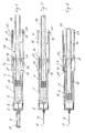
- FIGS. 1 to 3 each show in the same side view of an administration device of a first embodiment.
- the delivery device is an elongated injection pen.
- the administering device is intended for single use, for a single injection of a liquid medicament, which may in particular be a liquid formulation based on FSH or an FSH variant for hormonal treatment to stimulate the ovaries and consequent fertilization of the stimulated egg cells of pregnancy ,
- the liquid drug ie the liquid formulation, is not conserved, so it contains no preservatives. If it is preferably a formulation containing FSH or FSH variant, the drug must be administered after contact with the ambient air within a few minutes, if necessary within a few hours.
- FIG. 1 shows the delivery device in an initial state before use.
- the device comprises a sleeve-shaped housing 1 with a front, distal housing section, in which a reservoir 5 containing the medicament in a sterile state is accommodated, and a rear, proximal housing section, in which structures are formed, which are connected to a metering and conveying device of the device cooperate to allow the patient an individual choice of a dose of the drug to be administered.
- the proximal housing portion may also serve as a handle when administered. From the dosing and conveying device, a control element 13 can be seen, which protrudes in the proximal direction from the housing 1 at the proximal end.
- a dose display window 2 and a reservoir window 3 are formed. Through the window 2, the set dose is readable, and through the window 3, the reservoir 5 can be seen.
- the housing 1 has at the distal end a connecting portion 4, on which a needle unit can be attached. The needle unit is attached just prior to administration to ensure sterility of the drug by that time.
- FIG. 1 shows the administration device as I said in the initial state with sterile closed reservoir 5, more precisely in the storage state in which the device over can be stored for a longer period of at least several months, since the airtight, sterile closure of the reservoir 5 ensures the durability of non-preserved drugs.
- the patient immediately prior to administration includes a needle unit with an injection needle on the housing 1, namely in its connecting portion 4.
- the injection needle with a proximal needle portion punctures a septum which is an airtight of an outlet of the reservoir 5 and sterile closes.
- the drug is connected to the environment after piercing via the injection needle and, in the case of a preferably non-preserved drug based on FSH or an FSH variant, must be administered within a short time, preferably immediately.
- the reservoir 5 filled by the manufacturer contains a maximum dose of the drug that is sized to be sufficient for each of these patients across a larger group of potential patients. People who use a lower dose per administration may be able to self-adjust to this lower dose.
- the device is disposed of with the remaining in the reservoir 5 remaining amount of the drug after use. Furthermore, the device has the ability of priming, ie the venting of the reservoir 5. By priming possibly contained in the reservoir 5 free gas, in particular nitrogen or air, is displaced from the reservoir 5. Air can enter into the reservoir 5 during manufacture when filling the reservoir 5 or when connecting the injection needle 7. On the one hand, this air or, if appropriate, another gas should not be administered, but on the other hand also distorts the dose, since the dose administered would differ from the set dose by the amount of gas without priming in the reservoir 5.
- the delivery device comprises a delivery device 10 having a first delivery member 11 and a second delivery member 12.
- the first delivery member 11 is a piston 11 movably received in the reservoir 5 which seals the reservoir 5 at one end and a reservoir 5 in a forward drive direction along a central one Longitudinal axis A of the device is movable in the direction of the outlet.
- the injection needle 7 also extends axially on the axis A.
- the second conveyor member 12 forms a piston rod.
- the conveyor member 12 is in axial pressure contact with the piston 11, thus pushing the piston 11 upon actuation of the device by loose pressure contact axially in the direction of the outlet of the reservoir fifth
- the conveyor member 12 forms together with the housing 1 and a metering device.
- the conveyor member 12 will hereinafter be referred to as dosing and conveying member 12.
- the metering and delivery member 12 is rotatable relative to the housing 1 about the axis A to fulfill the metering function, thus performs a Dosiermosterrorism about the axis A when setting the dose.
- To fulfill the conveying function it is translationally movable along the axis A in the direction of advance.
- the metering and conveying member 12 forms the actuating element 13 with a proximal end portion.
- a Dosierblockierelement 16 is another of these structural elements.
- the first metering element 14 cooperates with the setting of the dose with a plurality of second metering elements 24 i , which are distributed around the longitudinal axis A and formed in a metering section 1 a of the housing 1 on the inner surface of the casing.
- the metering elements or guides 24 i have different axial lengths, these lengths each corresponding to an adjustable dose.
- the metering elements 24 i are formed, for example, on the inner circumference of the metering section 1a as axial blind slots.
- the blind grooves are open at their proximal ends, so that the first metering element 14 in accordance with the rotational angular position of the metering and conveying member 12 retract into one of these grooves 24 i in the advancing direction and in the course of a Aus thoroughlyhubs in the respective groove 24 i to its distal end can be moved in the advancing direction.
- the metering element 14 forms a discharge stop in double function by coming into axial stop contact at the end of the delivery stroke of the metering and delivery member 12 against a delivery stop 21 of the housing 1, which forms the distal end of the respective bag groove 24 i in the example.
- the length of the delivery stroke thus corresponds to the length of the dosing element 24 i which cooperates with the dosing element 14 as a function of the set dose.
- the metering and delivery member 12 forms with the housing 1 a Dosierrast issued.
- a metering detent structure 19 extending around the axis of rotation A is formed for this purpose.
- an elastically yielding dosing catch element 29, which is formed on the housing 1 slides in the form of a radially compliant snapper over the dome Dosierrast Quilt 19.
- the Dosierrast ceremoni 19 is formed in the manner of an external toothing, which is exemplarily formed directly on the outer surface of the metering and conveying member 12 preferably circumferentially about the axis A and whose pitch corresponds to the pitch of the second metering 24 i , so that the Dosierrastelement 29 each engages in a recess of Dosierrast réelle 19 when the metering element 14 is currently in axial alignment with one of the metering 24 i .
- a metering detent structure on the casing inner surface of the housing 1 and an elastically compliant metering detent element on the metering and conveying member 12 could also be formed.
- all functional structural elements are formed either on the housing 1 or on the metering and conveying member 12.
- the metering blocking element 16 and the metering detent structure 19 can also be formed separately from the remainder of the metering and conveying member 12, in particular on a sleeve part corresponding to the sleeve part of the embodiment which forms the outer periphery mentioned in the preceding paragraph.
- Such a separately shaped sleeve part with the Dosierblockierelement 16 and Dosierrastmilamila 19 would, however, preferably immovably with the housing 1 penetrating, the piston rod forming part of the dosing and conveying member 12 firmly joined. As a result, an assembled dosing and conveying member 12 would be obtained, which would correspond in shape to that of the embodiment.
- the metering and conveying member 12 In the initial state of the administering device ( FIGS. 1 and 4 ), the metering and conveying member 12 is in a Dosierblockiereingriff in which it is prevented from rotating about the axis A.
- the metering blocking engagement is effected by means of the metering blocking element 16, which is also formed on the metering and conveying member 12.
- the metering blocking member 16 is engaged with the housing 1 in the metering blocking engagement.
- the housing 1 forms for this purpose a rotational stop 22 as a blocking counter element.
- the Dosierblockiereingriff is formed in a particularly simple manner that the Dosierblockierelement 16 in the initial state in which the metering and delivery member 12 assumes its rearmost relative to the advancing direction position relative to the housing 1 and the reservoir 5, projects into the dose display window 2, so in that its left and right sidewalls act as a rotational stop 22 in clockwise and counterclockwise directions about the axis A.
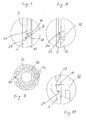
- FIG. 7 is the area in which the Dosierblockiereingriff exists in the initial state of the device, enlarged in detail.
- the Dosierblockierelement 16 projects beyond an outer peripheral surface of the metering and delivery member 12 radially outward into the dose display window 2. It is arranged on the metering and conveying member 12 so that it protrudes in relation to the advancing direction immediately behind a front end wall 23 of the window 2 into this and thus this end wall 23 is axially opposite.
- the Dosierblockierelement 16 in the circumferential direction about the axis A, the axis of rotation of the metering and conveying member 12, such a width that it as in FIG. 1 recognizable the window 2 in the circumferential direction almost completely fills, in Dosierblockiereingriff so in the circumferential direction has no "air” and virtually in close fit in both directions of rotation opposite to the rotational stops formed by the two side walls of the window 2.
- the effective in the two directions of rotation of the rotational movement stop surfaces of Dosierblockierelements 16 are provided with the reference numeral 17.
- the Dosierblockierelement 16 has over the two VerFDanschlag vom 17 also an inclined relative to the axis A axial guide surface 18 which cooperates with the axially opposite end face 23 of the dose display window 2. If a sufficiently large axial compressive force is exerted on the metering and delivery member 12, namely by pressure on the operating element 13, the metering blocking member 16 is pressed axially with its inclined guide surface 18 against the end face 23.
- the Dosierblockierglied 16 is radially elastically yielding with respect to the axis A, so that it slides on the end face 23 due to the inclined guide surface 18 and thereby passes radially inward and thus from the Dosierblockiereingriff with the left and right rotational stop 22 with respect to the direction of rotation ,
- the end face forms a deblocking stop 23.
- FIG. 8 the state is shown in which the Dosierblockierelement 16 has just passed the Deblockieranschlag 23 in the advancing direction, so that the metering and conveying member 12 from Dosierblockiereingriff free and rotatable about the axis A.
- FIG. 9 shows the administering device in a cross section in the region of the metering section 1a during the distribution of the drug.
- the metering element 14 is axially guided by one of the uniformly about the axis A in the metering section 1a shaped metering 24 i , so that the metering and conveying member 12 forcibly maintains the set during the dose selection rotational angular position during its Aus.thubs.
- the FIGS. 6 and 10 show the delivery device after complete release of the set dose, for example, the maximum dose was distributed.
- FIG. 6 shows the administration device in a longitudinal section, which is a few degrees about the axis A from the longitudinal sections of FIGS. 4 and 5 is offset.
- the longitudinal section of FIG. 6 extends through this metering 24 i .
- the dispensing stroke is terminated at the front end in the advancing direction of each of the metering elements 24 i by the respective delivery stop 21, in that the metering element 14 reaches the stop against the respective delivery stop 21 of the housing 1 in the advancing direction, such as FIG. 6 this shows.
- Each of the metering elements 24 i has a discharge stop 21 at its front end in the advancing direction, the delivery stopper 21 being shaped at different axial heights corresponding to the different cans.
- the administration device has, as a further special feature, a retaining device for the metering and delivery member 12.
- the retaining device ensures that the metering and conveying member 12 remains in the then occupied discharge position after completion of the Aus wellhubs. It comprises retaining elements 28 which are assigned to the metering elements 24 i , namely in each case one of the retaining elements 28 for each of the metering elements 24 i .
- FIG. 6 the retaining element 28 of the axially longest metering element 24 i and the retaining element 28 of the axially shortest metering element 24 i can be seen.
- the retaining elements 28 are formed by the housing 1 and are exemplarily formed on the inner lateral surface thereof as radially inwardly projecting retaining cams.
- the delivery stop 14, or the metering element 14 is inclined at a front side pointing in the advancing direction with respect to the axis A, so that it can slide in the advancing direction via the retaining element 28 of the respective metering element 24 i .
- the back of the discharge stop 14, respectively dosing 14 has at least substantially orthogonal to the axis A, so that he / she in cooperation with the respective retaining element 28 holds the metering and conveying member 12 in its dispensing position, either blocked against movement against the advancing direction or at least hindered such retraction movement. This ensures that the administration device can not be used carelessly for a further distribution if the dose set is smaller than the dose of medication in the reservoir 5 in the initial state.
- the patient receives the device in its initial state FIG. 1 , For administration, he connects the injection needle 7 to the reservoir 5 by inserting or screwing the needle holder 8 onto the connecting portion 4.
- This state shows FIG. 4 , The patient only has to remove the needle cap, which is in FIG. 4 the injection needle 7 covers.
- the reservoir 5 Prior to administration, the reservoir 5 must be vented.
- the delivery device enforces this priming step, because only after priming the dose to be administered can be adjusted.
- the ejected during priming volume is given, namely by the axial clear distance, the Aus commonlyanschlag 14 from the priming stop 25 has.
- Premature dose adjustment is prevented by the dosing blocking engagement between the dosing blocking element 16 and the rotational stop 22 of the housing 1.
- the Dosierblockiereingriff between 16 and 21 is particularly in FIG. 1 recognizable.
- the dose indicator provides the patient with the indication that he must perform a priming and how this happens.
- dose display window 2 appears in FIG. 1 recognizable display, a pictogram, pointing in the direction of advancement direction arrow and a "P" for "priming".
- the patient vented the reservoir 5 by exerting an axial compressive force on the control element 13.
- the elastically yielding Dosierblockierelement 16 radially inward by its guide surface 18 slides over the Deblockieranschlag 23 of the housing 1 and the Dosierblockierelement 16 by this slipping after moved radially inward from the Dosierblockiereingriff.
- the process is most evident from the FIGS. 7 and 8 seen.
- the priming stroke is limited by the priming stop 25, ie the priming stroke is terminated as soon as the delivery stop 14 reaches the stop against the priming stop 25.
- FIG. 5 shows the delivery device immediately after performing the priming stroke.
- the Dosierblockiereingriff is solved.
- the dose to be administered by the metering and conveying member 12 is rotated about the axis A in a rotational angular position in which the discharge stopper 14, when dosing as Dosing element 14 acts, in axial alignment with that of the metering elements 24 i , which corresponds in its axial length to the dose to be administered.
- the set dose is readable ( FIG. 2 ).
- the patient sets the delivery device with the injection needle 7 at the desired piercing point and pierces the injection needle 7 in and under the skin.
- the set dose is distributed by the patient moves by exerting an axial compressive force on the control element 13, the metering and conveying member 12 in the advancing direction.
- the metering and delivery member 12 presses against the piston 11 and this in the reservoir 5 in the direction of the outlet until the metering and delivery member 12 abuts with its discharge stop 14 against the discharge stop 21, which is assigned to the selected metering element 24 i .
- the delivery stroke of the metering and delivery member 12 and the piston 11, so the conveyor 10, corresponds to the axial length of the selected metering element 24 i .
- FIG. 9 shows the administering device in a cross section during the Aus thoroughlyhubs with the metering element 14 and Aus thoroughlyanschlag 14 in guiding engagement with the selected metering element 24 i .
- FIGS. 6 and 10 show the administering device after execution of the complete delivery stroke
- FIG. 10 shows the Area around the retaining element 28 in an enlarged detail.
- the metering and conveying member 12 is now in the retaining engagement, which prevents retraction of the metering and conveying member 12 against the advancing direction or at least severely hampered.
- the dose display through the window 2 through a blind indicator.
- the dose display 15 can be supplemented by a pictogram or a color marking or also a text in order to provide the patient with a positive feedback of the content that the set dose was completely distributed.
- the patient can recognize the piston 11. As a result, it is also visually signaled that the distribution was completed.
Landscapes
- Health & Medical Sciences (AREA)
- Vascular Medicine (AREA)
- Engineering & Computer Science (AREA)
- Anesthesiology (AREA)
- Biomedical Technology (AREA)
- Heart & Thoracic Surgery (AREA)
- Hematology (AREA)
- Life Sciences & Earth Sciences (AREA)
- Animal Behavior & Ethology (AREA)
- General Health & Medical Sciences (AREA)
- Public Health (AREA)
- Veterinary Medicine (AREA)
- Infusion, Injection, And Reservoir Apparatuses (AREA)
Description
Die Erfindung betrifft ein Verabreichungsgerät für ein flüssiges Medikament, das insbesondere eine flüssige Formulierung sein kann, die FSH oder eine FSH Variante enthält. Als flüssige Medikamente werden im Sinne der Erfindung nicht nur Flüssigkeiten im engeren Sinn angesehen, sondern auch pasten- und gelartige Medikamente, solange sich derartige Medikamente nur vergleichbar einer Flüssigkeit fördern lassen. Das Verabreichungsgerät ist vorzugsweise ein Injektionsgerät für die Verabreichung mittels einer infundierenden Injektionsnadel, bevorzugt für eine subkutane Injektion, kann grundsätzlich aber auch ein Injektionsgerät für eine nadellose Verabreichung oder beispielsweise auch ein Inhalationsgerät sein. Injektionsgeräte in Form sogenannter Injektionspens sind besonders bevorzugte Ausführungsbeispiele.The invention relates to an administration device for a liquid medicament, which may in particular be a liquid formulation containing FSH or an FSH variant. For the purposes of the invention, liquid medicaments are not only liquids in the narrower sense, but also paste and gelatinous medicaments, as long as such medicaments can only be promoted comparable to a liquid. The administration device is preferably an injection device for administration by means of an infusing injection needle, preferably for a subcutaneous injection, but in principle may also be an injection device for needleless administration or, for example, also an inhalation device. Injection devices in the form of so-called Injektionspens are particularly preferred embodiments.
Moderne Injektionspens ermöglichen die genaue Dosierung des Medikaments, individuell auch durch den jeweiligen Patienten selbst. Die durch die freie Auswahl der Dosis erhöhte Flexibilität ermöglicht den Einsatz in Therapien, in denen die Patienten sich das jeweilige Medikament selbst verabreichen, der sogenannten Selbstverabreichung. Gerade in der Selbstverabreichung sind eine hohe Bedienungssicherheit und ein hoher Bedienungskomfort gefordert. Die Geräte sollen Fehlbedienungen von Hause aus verhindern. Eine Fehlerquelle ist der Einschluss von Luft im Medikamentenreservoir. Wird diese Luft nicht vor der Verabreichung entfernt, besteht die Gefahr, dass nicht das Medikament in der eingestellten Dosis, sondern das Medikament gemeinsam mit der eingeschlossenen Luft entsprechend der eingestellten Dosis verabreicht wird. Das Medikamentenreservoir wird daher vor der Verabreichung entlüftet, ein Vorgang der allgemein unter dem Begriff des "Primen" bekannt ist. Bei einem Großteil der Geräte bleibt das Primen dem Gefühl des Patienten überlassen, der hierfür an einem Dosierglied eine kleine Dosis einstellt, das Gerät mit der Nadel nach oben hält und das eingestellte Primingvolumen durch Betätigung des Geräts ins Freie ausschüttet. Andere Geräte, beispielsweise ein aus der
Die
Die
Wegen der Notwendigkeit der Kostensenkung werden der Selbstverabreichung immer mehr Therapien erschlossen. Ein Beispiel ist die Stimulierung der Eierstöcke und daraus folgend durch Befruchtung der stimulierten Eizellen der Schwangerschaft durch Hormonbehandlung. So beschreibt beispielsweise die
Es ist eine Aufgabe der Erfindung, ein Verabreichungsgerät zu schaffen, das insbesondere in Therapien mit Selbstverabreichung eingesetzt werden kann, im Aufbau einfach und preiswert ist, aber dennoch eine sichere Gewähr für die Verabreichung genau der erforderlichen Dosis verbunden mit einem der Selbstverabreichung adäquaten Bedienungskomfort bietet. Das Gerät soll insbesondere für die Verabreichung einer flüssigen, nicht konservierten Formulierung, die FSH oder eine FSH Variante enthält, geeignet sein.It is an object of the present invention to provide an administering device which can be used particularly in self-administered therapies, which is simple and inexpensive in construction, but which nevertheless provides adequate assurance of the administration of precisely the required dose associated with self-administration. The device should be particularly suitable for the administration of a liquid, non-preserved formulation containing FSH or an FSH variant.
Die Erfindung hat ein Verabreichungsgerät zum Gegenstand, das ein Gehäuse, ein Reservoir für ein flüssiges Medikament, ein Dosierglied zum Einstellen einer zu verabreichenden Dosis des Medikaments und eine Fördereinrichtung mit einem Förderglied zum Ausschütten der eingestellten Dosis umfasst. Das Gehäuse kann unmittelbar das Reservoir bilden, falls beispielsweise eine Spritze das Gehäuse oder einen Teil des Gehäuses bildet. Das Reservoir kann insbesondere aber auch ein in dem Gehäuse aufgenommenes Behältnis, vorzugsweise in Form einer Karpule, sein. Das Dosierglied ist zum Einstellen der Dosis relativ zum Gehäuse beweglich. Die Bewegung, die das Dosierglied bei der Auswahl der Dosis ausführt, und die Beweglichkeit, die es für die Auswahl der Dosis relativ zum Gehäuse haben muss, werden im Folgenden als Dosierbewegung und Dosierbeweglichkeit bezeichnet. Die Fördereinrichtung kann insbesondere als Linearhub-Fördereinrichtung gebildet sein und dementsprechend einen axial beweglichen Kolben aufweisen, der das Reservoir an einem Ende steril abdichtet und im Falle einer Vortriebsbewegung Medikament durch einen Auslass des Reservoirs verdrängt und dadurch ausschüttet. Das genannte Förderglied kann den Kolben bilden. Bevorzugter bildet das Förderglied eine auf den Kolben wirkende Kolbenstange oder ist ein im Förderstrang noch weiter aufwärts angeordnetes Förderglied, das aber letztlich auf den Kolben oder ein anderes unmittelbar auf das im Reservoir befindliche Medikament wirkendes Förderglied abtreibt. Bei dem Förderglied handelt es sich in bevorzugten Ausführungen jedenfalls um eines, das eine Vortriebsbewegung, im folgenden auch als Ausschüttbewegung bezeichnet, ausführt.The invention relates to an administering device comprising a housing, a reservoir for a liquid medicament, a dosing member for adjusting a dose of medicament to be administered, and a conveyor having a delivery member for delivering the adjusted dose. The housing may directly form the reservoir if, for example, a syringe forms the housing or part of the housing. In particular, however, the reservoir can also be a container accommodated in the housing, preferably in the form of a carpule. The dosing member is movable relative to the housing for adjusting the dose. The movement which the dosing member makes in the selection of the dose and the mobility which it must have for the selection of the dose relative to the housing are referred to below as dosing movement and dosing mobility. The conveyor may in particular be formed as a linear stroke conveyor and accordingly have an axially movable piston which seals the reservoir at one end sterile and displaced in the event of a propelling movement drug through an outlet of the reservoir and thereby emits. The said conveyor member may form the piston. More preferably, the conveying member forms a piston rod acting on the piston or is a conveying member which is arranged even further upwards in the conveying string, but which ultimately aborts the piston or another conveying member acting directly on the medicament located in the reservoir. In any case, in the case of preferred embodiments, the conveying member is one which carries out a propelling movement, hereinafter also referred to as a dispensing movement.
In bevorzugten Ausführungen besteht das Verabreichungsgerät nur aus den genannten Komponenten, nämlich dem Gehäuse, dem Reservoir, dem Förderglied und dem Dosierglied, wobei das Förderglied und das Dosierglied vorzugsweise gemeinsam in einem Stück geformt oder alternativ durch zwei separat geformte und bevorzugterweise unbeweglich fest miteinander verbundene Teile gebildet werden. Bei Formung in einem einzigen Stück oder dem Fügen zu einer nur im Ganzen beweglichen Struktur werden die funktionalen Komponenten "Dosierglied" und "Förderglied" nachfolgend auch als "Dosier- und Förderglied" bezeichnet. Das Reservoir kann wie gesagt vom Gehäuse selbst gebildet werden, das in derartigen Ausführungen insbesondere als Spritze gebildet sein oder ein spritzenartiges Gehäuseteil aufweisen kann. Umfasst die Fördereinrichtung wie bevorzugt einen Kolben, so wird es bevorzugt, wenn der Kolben bereits von Hause aus im Reservoir angeordnet ist, also vom Hersteller im Reservoir angeordnet wird und nicht vom Patienten. Bei dem Kolben handelt es sich vorzugsweise um einen einfachen Stopfen ohne Kolbenstange. Die Kolbenstange oder ein vergleichbares anderes Förderglied wirkt nur in einem axialen Druckkontakt während der Förderung gegen die Rückseite des Kolbens, um diesen im Reservoir in die Vortriebsrichtung zu bewegen. Alternativ kann eine Kolbenstange aber auch beim Zusammenbau des Geräts formschlüssig mit einem einfachen Stopfen, der von Hause aus keine Kolbenstange aufweist, verbunden werden. Der Zusammenbau des Geräts wird vorzugsweise vom Gerätehersteller oder dem Medikamentenhersteller vorgenommen, so dass der Patient oder auch ein die Therapie gegebenenfalls begleitender Arzt das fertige Gerät mit dem bereits mit dem Medikament gefüllten Reservoir erhält und lediglich noch die Verabreichung als solche vornehmen muss.In preferred embodiments, the delivery device consists only of the said components, namely the housing, the reservoir, the delivery member and the dosing member, wherein the delivery member and the dosing member are preferably molded together in one piece or alternatively by two separately formed and preferably immovably rigidly interconnected members be formed. When forming in a single piece or joining to a structure that is only movable as a whole, the functional components "dosing member" and "conveying member" are also referred to below as "dosing and conveying member". The reservoir can be said to be formed by the housing itself, which may be formed in such embodiments in particular as a syringe or may have a syringe-like housing part. Includes the conveyor as preferred a piston, so It is preferred if the piston is already arranged in the reservoir from home, so it is arranged by the manufacturer in the reservoir and not by the patient. The piston is preferably a simple plug without a piston rod. The piston rod or a comparable other delivery member acts only in axial pressure contact during the promotion against the back of the piston to move it in the reservoir in the advancing direction. Alternatively, a piston rod but also during assembly of the device can be positively connected with a simple plug, which has no piston rod from home. The assembly of the device is preferably carried out by the device manufacturer or the drug manufacturer, so that the patient or a doctor possibly accompanying the doctor receives the finished device with the already filled with the drug reservoir and only has to make the administration as such.
Das Dosierglied ist in einem Ausgangszustand des Verabreichungsgeräts, in dem der Patient das Gerät vorzugsweise erhält, in einem lösbaren Dosierblockiereingriff in Richtung der Dosierbewegung blockiert und kommt erst am Ende einer der Entlüftung des Reservoirs dienenden Primingbewegung des Förderglieds von der Blockierung frei, automatisch ohne weiteres Zutun des Patienten, der nur die Primingbewegung bewirken muss. Das Förderglied führt die Primingbewegung in eine Richtung quer zur Richtung der Dosierbewegung aus. Die Richtung der Primingbewegung des Förderglieds ist auch die Vortriebsrichtung bei der Ausschüttbewegung. Die Vortriebsrichtung wird im Folgenden auch als axiale Richtung bezeichnet, sie erfolgt vorzugsweise längs einer zentralen Längsachse des Geräts. Nach der Erfindung ist das Dosierglied durch eine in die Vortriebsrichtung wirkende Kraft gegen eine elastische Rückstellkraft in die Vortriebsrichtung aus dem Dosierblockiereingriff bewegbar.The dosing member is blocked in a starting state of the administering device, in which the patient preferably receives the device in a releasable Dosierblockiereingriff in the direction of dosing and comes only at the end of a priming movement of the reservoir serving priming movement of the conveyor element free from blocking, automatically without further action of the patient, who only has to effect the priming movement. The conveying member carries out the priming movement in a direction transverse to the direction of the metering movement. The direction of the priming movement of the conveyor member is also the direction of advance in the dispensing movement. The propulsion direction is also referred to below as the axial direction, it is preferably along a central longitudinal axis of the device. According to the invention, the dosing member is movable by a force acting in the advancing direction against an elastic restoring force in the advancing direction from the Dosierblockiereingriff.
Das Verabreichungsgerät verfügt somit über eine Ablaufsteuerung, die einen bestimmten Ablauf bei der Verabreichung erzwingt und in diesem Sinne steuert. Aufgrund des Dosierblockiereingriffs muss das Reservoir vor dem Einstellen der Dosis entlüftet werden. Die Ablaufsteuerung ist in bevorzugter Ausführung ferner so verwirklicht, dass vor dem Ausschütten des Medikaments die Dosis eingestellt werden muss, so dass die Verabreichung nur in der Sequenz "Primen - Dosieren - Ausschütten" ablaufen kann.The delivery device thus has a sequencer that enforces and controls a particular procedure during administration. Due to the dosing blocking procedure, the reservoir must be vented before adjusting the dose. The sequence control is further realized in a preferred embodiment, that before the dispensing of the drug, the dose must be set, so that the administration can run only in the sequence "priming - dosing - dumping".
Das Dosierglied ist für die Einstellung der Dosis quer zu der Vortriebsrichtung beweglich. Eine Dosierdrehbeweglichkeit um eine Rotationsachse, die insbesondere mit einer zentralen Längsachse des Geräts zusammenfallen kann, wird besonders bevorzugt. In derartigen Ausführungen ist das Dosierglied im Dosierblockiereingriff in Umfangsrichtung um die Rotationsachse gegen einen Verdrehanschlag auf Anschlag, drückt also bei dem Versuch der Einstellung einer Dosis in Bezug auf die Rotationsachse in tangentialer Richtung gegen den Verdrehanschlag. Vorzugsweise ist das Dosierglied und die Rotationsachse hin und her drehbeweglich und in Bezug auf beide Drehrichtungen in einem Dosierblockiereingriff, drückt also beim Versuch der Verdrehung in beide Drehrichtungen gegen jeweils einen Verdrehanschlag.The dosing member is movable transversely to the direction of advance for setting the dose. A Dosierdrehbeweglichkeit about an axis of rotation, which may coincide in particular with a central longitudinal axis of the device, is particularly preferred. In such embodiments, the dosing in the Dosierblockiereingriff in the circumferential direction about the rotation axis against a rotational stop to stop, so presses in the attempt to set a dose with respect to the axis of rotation in the tangential direction against the rotational stop. Preferably, the dosing member and the rotation axis is rotatable back and forth and in relation to both directions of rotation in a Dosierblockiereingriff, so suppressed when trying to twist in both directions against each a rotational stop.
Das Dosierglied ist in Vortriebsrichtung des Förderglieds längs des Verdrehanschlags aus dem Dosierblockiereingriff beweglich. Bevorzugterweise wird es bei der Primingbewegung des Förderglieds und noch bevorzugter durch die Primingbewegung automatisch längs des Verdrehanschlags oder des bevorzugt linken und rechten Verdrehanschlags aus dem Dosierblockiereingriff bewegt. Bevorzugten Ausführungen entspricht es, wenn das Dosierglied mit dem Förderglied so gekoppelt ist, dass es die Primingbewegung des Förderglieds mitmacht. Das Dosierglied und das Förderglied können insbesondere in einem Stück gemeinsam geformt oder als separate Teile geformt und fest miteinander gefügt sein.The dosing member is movable in the advancing direction of the conveying member along the Verdrehanschlags from Dosierblockiereingriff. Preferably, during the priming movement of the conveyor member, and more preferably by the priming motion, it is automatically moved out of the metering block engagement along the rotational stop or the preferably left and right rotational stops. Preferred embodiments it corresponds when the dosing member is coupled to the conveying member so that it participates in the priming movement of the conveying member. The dosing member and the conveying member may in particular be formed together in one piece or formed as separate parts and be firmly joined together.
Die Erfindung eröffnet auch Wege für eine sichere Verabreichung von flüssigen Medikamenten, deren Wirkstoff(e) an Luft der Gefahr der Kontamination unterliegt, wie insbesondere Formulierungen, die als wesentlichen Wirkstoff FSH oder eine FSH Variante enthalten. Dabei ist es ein besonderes Anliegen, den Einsatz von Konservierungsmitteln zu vermeiden, nicht zuletzt im Hinblick auf negative Auswirkungen auf den oder die jeweiligen Wirkstoff(e), aber auch auf die zusätzlichen Kosten, die durch die Beimischung von Konservierungsmitteln entstehen. Nach der Erfindung wird das Reservoir mit dem nicht konservierten flüssigen Medikament an den Patienten abgegeben, vorzugsweise in Form eines kompletten Verabreichungsgeräts oder eines mit einfachen Handgriffen montierbaren Geräteteils. Das nicht konservierte, bei Anwesenheit von Luft kontaminationsgefährdete Medikament ist in dem bis unmittelbar vor Verabreichung steril geschlossenen Reservoir sicher aufbewahrt, so dass es in diesem Zustand über einen Zeitraum von mehreren Tagen oder durchaus auch Monaten oder Jahren aufbewahrt werden kann. Die Sterilität wird erst unmittelbar vor Gebrauch vom Patienten oder einem verabreichenden Arzt aufgehoben.The invention also opens up ways for a safe administration of liquid medicaments whose active substance (s) in air is subject to the risk of contamination, in particular formulations which contain FSH or an FSH variant as the essential active substance. It is particularly important to avoid the use of preservatives, not least in terms of negative effects on the respective active ingredient (s), but also on the additional costs that result from the admixture of preservatives. According to the invention, the reservoir with the non-preserved liquid medicament is delivered to the patient, preferably in the form of a complete administering device or a device part which can be assembled with simple handles. The non-preserved, in the presence of air contaminated drug is in the sterile until immediately before administration closed reservoir safely stored so that it can be stored in this condition for a period of several days or even months or years. Sterility is not reversed until immediately before use by the patient or an administering physician.
Die Erfindung betrifft insbesondere ein erfindungsgemäßes Verabreichungsgerät mit Ablaufsteuerung, dessen Reservoir steril geschlossen ist und ein flüssiges Medikament in Form beispielsweise einer flüssigen Formulierung von FSH oder einer FSH Variante enthält. Die Verwendung von Karpulen oder Spritzen, die ein nicht konserviertes Medikament, beispielsweise FSH oder eine nicht konservierte FSH Variante, in sterilem und daher auch ohne Konservierungsmittel haltbaren Zustand enthalten, ist von Vorteil Weitere Medikamente, die nach der Erfindung in nicht konserviertem Zustand in einem steril verschlossenen Reservoir des Verabreichungsgeräts und somit praktisch zeitlich unbegrenzt im Handel, beim Arzt oder auch bereits beim jeweiligen Patienten aufbewahrt werden können, sind beispielsweise Neuroleptica (Fluphenazini decanoas), gefäßerweiternde Mittel (Adrenalinum), Blutprodukte (Etamsylat, Epoetin alfa, Filgrastim (G-CSF), Nadroparinum calcium, Desmopressini acetas), Medikamente gegen rheumatische Erkrankungen (Methotrexat, Etanerceptum), Onkologica (Cladribinum, Interferonum humanum gamma-1b ADN) und Medikamente gegen Infektionskrankheiten (Herpes simplex Typ1/Typ2, humanes Immunglobulin). In Klammern sind übliche oder bevorzugte Wirkstoffe für die jeweilige Medikamentengruppe angegeben.More particularly, the invention relates to an administration device according to the invention with a flow control, the reservoir of which is sterile closed and contains a liquid medicament in the form of, for example, a liquid formulation of FSH or an FSH variant. The use of cartridges or syringes which contain an unpreserved drug, for example FSH or an unpreserved FSH variant, in a sterile and therefore preservative-free condition is advantageous. Further medicaments which according to the invention are in a non-preserved state are sterile For example, Neuroleptica (Fluphenazini decanoas), vasodilatory agents (adrenaline), blood products (Etamsylate, Epoetin alfa, Filgrastim (G-CSF), etc.) can be stored in the closed reservoir of the administering device and thus practically indefinitely in commerce, the doctor or even the respective patient ), Nadroparinum calcium, desmopressini acetas), medicines for rheumatic diseases (methotrexate, etanerceptum), oncologica (cladribinum, interferonum humanum gamma-1b ADN) and medicines for infectious diseases (herpes
Ein FSH basiertes Medikament enthält vorzugsweise eine alpha- und eine beta-Untereinheit. Die Proteine für die verwendbaren Formulierungen können durch verschiedene Verfahren gewonnen werden. Vorzugsweise ist das einzusetzende FSH ein Heterodimer, das eine α-Untereinheit und eine β-Untereinheit umfasst, wie sie in der
Insbesondere für die Verabreichung von nicht konservierten flüssigen Medikamenten, wie die Verabreichung flüssiger Formulierungen von FSH oder einer FSH Variante, ist es von Vorteil, wenn im steril geschlossenen Reservoir nur eine Medikamentenmenge aufbewahrt wird, die höchstens so groß wie eine Tagesdosis, noch bevorzugter wie eine Maximaldosis (Monodosis) ist, in der das betreffende Medikament in einer einzigen Verabreichung von höchstens einigen Minuten Dauer, vorzugsweise einer einzigen Injektion, verabreicht wird. Das Reservoir und somit auch das Verabreichungsgerät sind daher vorzugsweise ein Reservoir und ein Verabreichungsgerät für eine Monodosis des Medikaments. Die Maximaldosis für Medikamente auf der Basis von beispielsweise FSH oder einer FSH Variante ist typischerweise 300 IU, in Ausnahmefällen 500 IU, gemessen über eine Vielzahl von Patienten. Die im Reservoir befindliche Medikamentenmenge entspricht im Falle solch eines Medikaments daher in bevorzugten Ausführungen höchstens einer Dosis von 500 IU, bevorzugter höchstens 300 IU. Da eine Mehrzahl der Patienten mit deutlich geringeren Dosen pro Einzelverabreichung auskommt, beispielsweise mit höchstens 200 IU oder auch nur höchstens 100 IU, kann die Füllmenge in solch einer Therapie vorteilhafterweise auch höchstens dieser Dosis entsprechen.In particular for the administration of non-preserved liquid medicaments, such as the administration of liquid formulations of FSH or an FSH variant, it is advantageous if only a quantity of medicament is stored in the sterile closed reservoir which is at most as large as a daily dose, more preferably as one Maximum dose (monodose) in which the drug in question is administered in a single administration of at most a few minutes' duration, preferably a single injection. The reservoir and thus also the administering device are therefore preferably a reservoir and a delivery device for a monodose of the medicament. The maximum dose for drugs based on, for example, FSH or an FSH variant is typically 300 IU, in exceptional cases 500 IU, measured across a variety of patients. In the case of such a medicament, therefore, the amount of medicament present in the reservoir corresponds at most to a dose of 500 IU, more preferably at most 300 IU, in preferred embodiments. Since a majority of patients manage with significantly lower doses per single administration, for example with at most 200 IU or even at most 100 IU, the filling quantity in such a therapy can advantageously also correspond at most to this dose.
In einer Weiterentwicklung werden die Verabreichungsgeräte jeweils mit einem Reservoir angeboten, das eine dem tatsächlichen Bedürfnis des jeweiligen Patienten genauer angepasste Füllmenge aufweist. So können baugleiche Verabreichungsgeräte beispielsweise in zwei, drei oder mehr unterschiedlichen Füllmengenvarianten zum Einsatz gelangen. Im Falle beispielsweise einer FSH-basierten Therapie können Verabreichungsgeräte der gleichen Bauart angeboten werden, die sich im Wesentlichen nur hinsichtlich der Füllmenge ihres Reservoirs voneinander unterscheiden, beispielsweise ein Gerät mit einem Reservoir, das 300 IU des Medikaments, ein weiteres Gerät, das 200 IU des gleichen Medikaments und noch ein Gerät, das 100 IU des Medikaments enthält, jeweils im sterilen Zustand. Es kann auch eine nochmalige Unterteilung in Zwischenstufen vorgenommen werden, beispielsweise in Form einer vierten Füllmengenvariante mit einem Reservoir, dass 150 IU des Medikaments im sterilen Zustand enthält. Das Gerät ist vorzugsweise jeweils für den einmaligen Gebrauch konzipiert, als Einwegartikel, und kann vorteilhafterweise über den Hausmüll entsorgt werden. Erst unmittelbar vor der Verabreichung wird das Medikament im bis zu diesem Zeitpunkt steril geschlossenen Reservoir mit der äußeren Umgebung in Kontakt gebraucht.In a further development, the administration devices are each provided with a reservoir which has a more accurate fit to the actual needs of the respective patient. For example, identical administration devices can be used, for example, in two, three or more different filling quantity variants. For example, in the case of FSH-based therapy, administration devices of the same type can be offered, which essentially differ only in terms of the amount of their reservoir, for example, one device with a reservoir, the 300 IU of the drug, another device, the 200 IU of the same drug and another device that contains 100 IU of the drug, each in the sterile state. It can also be made a second subdivision into intermediate stages, for example in the form of a fourth filling variant with a reservoir containing 150 IU of the drug in the sterile state. The device is preferably designed for single use, as a disposable item, and can be advantageously disposed of with household waste. Immediately prior to administration, the drug is placed in contact with the external environment in the reservoir, which has until then been sterile.
Für den sterilen Verschluss des Reservoirs kommen insbesondere zwei Varianten in Betracht. In der ersten Variante bildet eine Karpule das Reservoir, die für die Verabreichung einen Auslass aufweist, der von einem durchstechbaren Septum steril verschlossen wird. Das Medikament ist in derartigen Ausführungen zwischen dem Septum und einem axial beweglichen Kolben steril eingeschlossen. Mit einem derartigen Reservoir kommt eine Nadeleinheit zum Einsatz mit einem Nadelhalter und einer den Nadelhalter durchragenden Injektionsnadel. Der Nadelhalter dient der Halterung der Injektionsnadel und der Herstellung des Fluidanschlusses der Nadel an das Reservoir. Für den Anschluss kann unmittelbar das Reservoir oder vorzugsweise das Gehäuse einen Verbindungsabschnitt im Bereich des Auslasses des Reservoirs aufweisen. Der Verbindungsabschnitt und ein Verbindungsabschnitt des Nadelhalters sind kooperierend ausgebildet, so dass bei Herstellung der mechanischen Verbindung zwischen dem Nadelhalter und dem Verbindungsabschnitt des Reservoirs oder des Gehäuses die Injektionsnadel das Septum durchsticht. Nach dem Durchstechen ist der Innenraum des Reservoirs über die Nadel mit der Umgebung verbunden. Im Anschluss an die Herstellung dieser Fluidverbindung wird möglichst ohne Verzug das Medikament verabreicht. Anschließend wird das Verabreichungsgerät oder zumindest ein das vollständig oder teilweise entleerte Reservoir enthaltender Teil des Geräts, gegebenenfalls auch nur das Reservoir, entsorgt. In der zweiten Variante bildet eine Spritze oder spritzenähnliches Gebilde das Reservoir. Im Unterschied zur ersten Variante weist das Reservoir der zweiten Variante an seinem distalen Ende bereits eine Injektionsnadel auf, so dass von Hause aus bereits die Fluidverbindung zwischen dem Reservoir und einem stromabwärtigen Auslass der Injektionsnadel besteht. Für den sterilen Verschluss sorgt ein externes Dichtelement, das den Nadelauslass steril verschließt. Das Dichtelement wird unmittelbar vor Gebrauch abgezogen.For the sterile closure of the reservoir in particular two variants come into consideration. In the first variant, a carpule forms the reservoir, which has an outlet for administration, which is sterile-closed by a pierceable septum. The medicament is sterile enclosed in such embodiments between the septum and an axially movable piston. With such a reservoir, a needle unit is used with a needle holder and an injection needle projecting through the needle holder. The needle holder serves to hold the injection needle and to establish the fluid connection of the needle to the reservoir. For the connection, the reservoir or preferably the housing may directly have a connection section in the region of the outlet of the reservoir. The connecting portion and a connecting portion of the needle holder are cooperatively formed, so that upon establishment of the mechanical connection between the needle holder and the connecting portion of the reservoir or the housing, the injection needle pierces the septum. After piercing, the interior of the reservoir is connected to the environment via the needle. Following the preparation of this fluid connection the drug is administered as possible without delay. Subsequently, the administration device or at least one part of the device containing the completely or partially empty reservoir, if appropriate only the reservoir, is disposed of. In the second variant, a syringe or syringe-like structure forms the reservoir. In contrast to the first variant, the reservoir of the second variant already has an injection needle at its distal end, so that the fluid connection between the reservoir and a downstream outlet of the injection needle already exists from home. The sterile closure is provided by an external sealing element, which seals the needle outlet in a sterile manner. The sealing element is removed immediately before use.
Auch für Therapien mit nicht konserviertem Medikament oder einem für nur eine einzige Verabreichung befüllten Reservoir, einer Monodosis, ist es von Vorteil, wenn das Verabreichungsgerät über die Fähigkeit der Dosierbarkeit verfügt, also das zuvor genannte Dosierglied aufweist. Auf diese Weise kann trotz einer optionalen Vielfalt von Varianten hinsichtlich der Füllmenge für jeweils nur eine einzige Verabreichung in jeder Variante nochmals die Dosis genauer eingestellt werden. Es kann mit anderen Worten durch die Bereitstellung mehrerer Füllmengenvarianten die Medikamentenmenge über viele Patienten gesehen insgesamt verringert werden, nämlich im Vergleich zu Ausführungen, in denen das Reservoir jeweils die Maximaldosis enthält, die innerhalb der Therapie überhaupt in einer einzigen Verabreichung ausgeschüttet wird. Andererseits kann der einzelne Patient innerhalb der passend gewählten Füllmengenvariante nochmals individuell die auf ihn zugeschnittene Dosis einstellen und auch nur diese sich verabreichen.It is also advantageous for therapies with unpreserved medicament or a reservoir filled for a single administration, a monodose, if the administering device has the ability to be metered, that is to say has the aforementioned metering element. In this way, despite an optional variety of variants in terms of the filling amount for each only a single administration in each variant again the dose can be set more accurately. It can be done by other words Provision of several types of filling the amount of medication over many patients are reduced overall, namely compared to versions in which the reservoir each contains the maximum dose that is distributed within the therapy at all in a single administration. On the other hand, the individual patient within the appropriately selected filling quantity variant can individually adjust the dose tailored to him and even administer it only.
Es wird bevorzugt, wenn das Primen und anschließend das Ausschütten der eingestellten Dosis richtungsgleiche Bewegungen sind, vorzugsweise axiale Bewegungen in die Vortriebsrichtung eines das Medikament verdrängenden Kolbens. So verhindert der Dosierblockiereingriff im Ausgangszustand Dosierbewegungen des Dosierglieds, ermöglicht jedoch den Priminghub, durch den das Dosierglied am Ende aus dem Dosierblockiereingriff und gegen einen Priminganschlag in Druckkontakt, vorzugsweise in axialen Druckkontakt gelangt. Nach Ausführung des Priminghubs, insbesondere im Kontakt mit dem Priminganschlag, ist das Dosierglied quer zur Richtung der Primingbewegung beweglich, um die gewünschte Dosis einstellen zu können. In bevorzugten Ausführungen sind das Dosierglied und das Förderglied in Bezug auf die Richtung des Priminghubs fest miteinander verbunden, beispielsweise in einem Stück geformt. Sollten die beiden Glieder diesbezüglich relativ zueinander in alternativen Ausführungen beweglich sein, kann entweder das Dosierglied in den Anschlagkontakt mit dem Priminganschlag gelangen oder, bevorzugter, das Förderglied.It is preferred if the priming and then the dispensing of the set dose are directionally identical movements, preferably axial movements in the advancing direction of a piston displacing the medicament. Thus, the Dosierblockiereingriff prevented in the initial state metering movements of the dosing, but allows the priming stroke, through which the dosing at the end of the Dosierblockiereingriff and against a Priminganschlag in pressure contact, preferably in axial pressure contact. After execution of the priming stroke, in particular in contact with the priming stop, the dosing member is movable transversely to the direction of the priming movement in order to set the desired dose can. In preferred embodiments, the dosing member and the conveying member are fixedly connected to one another, for example in one piece, with respect to the direction of the priming stroke. If the two members in this respect be movable relative to each other in alternative embodiments, either the dosing member can come into abutting contact with the priming stop or, more preferably, the conveying member.
In bevorzugten Ausführungen ist ein Rückhalteelement vorgesehen, mit dem das Förderglied im Verlaufe seiner Ausschüttbewegung in einen Rückhalteeingriff gelangt, der eine Bewegung des Förderglieds gegen die Vortriebsrichtung blockiert oder zumindest erschwert. Einer Blockierung wird zwar der Vorzug gegeben, ein lösbarer Rückhalteeingriff ist jedoch ebenfalls von Vorteil. Um in den Rückhalteeingriff zu gelangen, bewegt sich das Förderglied bei der Ausschüttbewegung vorteilhafterweise über das Rückhalteelement hinweg, so dass ein hörbares oder fühlbares Klick-Geräusch entsteht. Das Rückhalteelement und ein entsprechendes Eingriffsgegenelement des Förderglieds sind relativ zueinander vorteilhafterweise so angeordnet, dass sich der Rückhalteeingriff automatisch erst am Ende der Ausschüttbewegung einstellt, so dass dem Patienten hörbar oder fühlbar signalisiert wird, dass die Ausschüttung vollständig vorgenommen wurde.In preferred embodiments, a retaining element is provided with which the conveying member passes in the course of its dispensing movement in a retaining engagement, which blocks or at least complicates movement of the conveying member against the advancing direction. While blocking is preferred, releasable retention is also beneficial. In order to get into the retaining engagement, the conveying member moves during the dispensing movement advantageously over the retaining element away, so that an audible or tactile clicking sound is created. The retaining element and a corresponding engagement counter-element of the conveying member are advantageously arranged relative to each other so that the retaining engagement automatically only at the end the delivery movement, so that the patient is audibly or tactilely signaled that the distribution was made in full.
Um die Herstellkosten auch von Verabreichungsgeräten so niedrig wie möglich zu halten, die die Einstellung der Dosis erlauben, schlägt die Erfindung vor, das Gehäuse, und die Funktionen des Primens und Förderns und, soweit verwirklicht, auch des Dosierens durch insgesamt nur zwei oder drei getrennt geformte Teile zu verwirklichen. Falls das Reservoir ein im Gehäuse aufgenommenes Behältnis, vorzugsweise eine Karpule ist, kommt das Behältnis noch dazu, gemeinsam mit einem das Behältnis verschließenden Kolben. Diese Teile können insbesondere im Spritzguss aus Kunststoff geformt sein, wobei ein aufgenommenes Behältnis auch aus Glas gefertigt sein kann. So kann das Gehäuse mit dem Dosierglied bereits alleine sämtliche Dosierfunktionen des Verabreichungsgeräts erfüllen, das Dosierglied und das Gehäuse somit bereits allein eine vollständige Dosiereinrichtung bilden. Das Gehäuse kann auch mit dem Dosierglied im Ausgangszustand in dem Dosierblockiereingriff sein, insbesondere den in bevorzugten Ausführungen vorhandenen Verdrehanschlag unmittelbar bilden. Ein Betätigungselement durch dessen Betätigung die Ausschüttung ausgelöst wird, kann vorteilhafterweise in einem Stück mit dem Förderglied geformt sein. Das gleiche Betätigungselement kann auch in einem Stück mit dem Dosierglied geformt sein und dessen Bedienbereich für die Dosiseinstellung bilden. Falls das Förderglied separat von dem Dosierglied gefertigt ist, sind die beiden Teile im zusammengebauten Zustand des Geräts vorzugsweise axial oder rotatorisch fest miteinander gefügt. Das Wort "oder" wird hier wie auch sonst stets von der Erfindung im üblichen logischen Sinne von "inklusiv oder" verwendet, umfasst also sowohl die Bedeutung von "entweder .... oder" als auch die Bedeutung von "und", soweit sich aus dem jeweils konkreten Zusammenhang nicht ausschließlich nur eine dieser Bedeutungen ergeben kann. Bezogen auf die Fertigung des Dosierglieds und Förderglieds als getrennte Teile bedeutet dies für den gefügten Zustand, dass das Förderglied und das Dosierglied entweder nur axial relativ zueinander unbeweglich oder nur rotatorisch relativ zueinander unbeweglich oder aber, wie bevorzugt, sowohl axial als auch rotatorisch relativ zueinander unbeweglich miteinander gefügt sind. In einer bevorzugten Modifikation bildet ein in einem einzigen Stück geformtes Dosier- und Förderglied eine Kolbenstange, wenigstens ein für die Auswahl der Dosis erforderliches Dosierelement, einen den Ausschütthub begrenzenden Ausschüttanschlag und ein Bedienelement für die Auswahl der Dosis oder die Betätigung zum Ausschütten. Bevorzugt bildet solch ein Dosier- und Förderglied auch noch einen Priminganschlag für die Begrenzung des Priminghubs. Von den drei genannten Formelementen, dem Dosierelement, dem Ausschüttanschlag und dem Priminganschlag, können zwei oder bevorzugt alle drei vom gleichen Formelement gebildet werden. Das Dosierblockierelement kann ebenfalls in einem Stück am Dosier- und Förderglied geformt sein, ebenso ein optionales Dosierrastelement oder eine Dosierraststruktur zur Einstellung der Dosis in diskreten Schritten. Das Dosierblockierelement oder Dosierrastelement oder die Dosierraststruktur kann oder können in bevorzugten Abwandlungen auch separat von dem die genannten verbleibenden Funktionen aufweisenden Dosier- und Förderglied geformt und mit diesem vorzugsweise fest, d. h. translatorisch und rotatorisch unbeweglich gefügt sein.In order to keep the manufacturing costs of administration devices as low as possible, which allow the adjustment of the dose, the invention proposes to separate the housing, and the functions of priming and conveying and, as far as realized, of dosing by a total of only two or three to realize molded parts. If the reservoir is a container accommodated in the housing, preferably a carpule, the container still arrives, together with a piston closing the container. These parts can be molded in particular by injection molding of plastic, wherein a recorded container can also be made of glass. Thus, the housing with the dosing alone already fulfill all dosing functions of the administering device, the dosing and the housing thus alone form a complete metering device. The housing may also be in the Dosierblockiereingriff with the dosing member in the initial state, in particular directly form the existing in preferred embodiments, rotational stop. An actuator by the actuation of the discharge is triggered, may advantageously be formed in one piece with the delivery member. The same actuator can also be molded in one piece with the dosing and form its operating range for the dose setting. If the conveyor member is made separately from the dosing member, the two parts are preferably axially or rotationally fixed together in the assembled state of the device. The word "or" is used here as well as elsewhere by the invention in the usual logical sense of "inclusive or", thus encompassing both the meaning of "either .... or" and the meaning of "and" as far as from the respective concrete context can not exclusively give only one of these meanings. Based on the production of the dosing and conveying member as separate parts, this means for the joined state that the conveying member and the dosing either immovable only axially relative to each other or immovable only rotatory relative to each other or, as preferred, both axially and rotationally immovable relative to each other are joined together. In a preferred modification, a metering and delivery member formed in a single piece forms a piston rod, at least one metering element required for the selection of the dose, a delivery stop limiting the delivery stroke, and a Control element for dose selection or actuation for dispensing. Such a metering and delivery member preferably also forms a priming stop for limiting the priming stroke. Of the three mentioned form elements, the metering element, the delivery stop and the priming stop, two or preferably all three of the same shaped element can be formed. The dosing blocking element can also be molded in one piece on the dosing and conveying member, as well as an optional Dosierrastelement or Dosierraststruktur for setting the dose in discrete steps. The Dosierblockierelement or Dosierrastelement or the Dosierraststruktur may or may also be formed separately from the said remaining functions having dosing and conveying member in preferred modifications and preferably rigid, ie translationally and rotationally immovably joined thereto.
Ein Verabreichungsgerät, das die Einstellung der Dosis erlaubt, verfügt vorzugsweise über eine Dosisanzeige mit einer Dosisskala und einem Marker, dessen Position relativ zur Dosisskala die eingestellte Dosis anzeigt. Der Marker kann insbesondere von einem Fenster in einem Schalenabschnitt des Gehäuses gebildet werden, durch das die Dosisskala ablesbar ist. Die Dosisskala kann insbesondere auf einer äußeren Umfangsfläche des Dosierglieds gebildet sein, die bei der Einstellung der Dosis unter dem Fenster durchläuft. Anstatt im Gehäuse ein Fenster zu formen, kann das Gehäuse auch bereichsweise oder im Ganzen aus einem transparenten oder transluzenten Material gefertigt sein und einen Marker in Form eines Aufdrucks oder eines abragenden Formelements aufweisen.An administering device that allows dose adjustment preferably has a dose display with a dose scale and a marker whose position relative to the dose scale indicates the set dose. The marker can in particular be formed by a window in a shell section of the housing, through which the dose scale can be read. The dose scale may in particular be formed on an outer circumferential surface of the dosing member, which passes through the setting of the dose under the window. Instead of forming a window in the housing, the housing can also be made in regions or as a whole from a transparent or translucent material and have a marker in the form of an imprint or a projecting formula element.
In einer Weiterentwicklung kann solch eine Dosisanzeige den Anschlag, vorzugsweise Verdrehanschlag, für die Blockierung des Dosierglieds im Dosierblockiereingriff bilden. Der Dosierblockieranschlag kann insbesondere von einer Seitenwand des Fensters oder von einem als Abragung geformten Marker gebildet werden. Das gleiche Fenster kann noch einen weiteren Anschlag bilden, nämlich einen Anschlag, den das Dosierglied in Richtung der Primingbewegung überwinden muss, um aus dem Dosierblockiereingriff zu gelangen. Dieser optionale weitere Anschlag muss vorteilhafterweise gegen die elastische Rückstellkraft überwunden werden, wobei die Rückstellkraft quer zur Richtung der Primingbewegung weist. Die Rückstellkraft kann insbesondere von einem elastischen Schnapper, einer Biegezunge, bereitgestellt werden, die am Dosierglied geformt ist. In Umkehrung der Verhältnisse kann solch ein Schnapper auch am Gehäuse geformt sein. Gegebenenfalls können auch ein elastischer Schnapper des Dosierglieds und ein elastischer Gegenschnapper des Gehäuses in der geschilderten Weise zusammenwirken, um das Dosierglied lösbar im Dosierblockiereingriff zu halten.In a further development, such a dose indicator can form the stop, preferably a twist stop, for blocking the dosing member in the dosing blocking engagement. The Dosierblockieranschlag can in particular be formed by a side wall of the window or by a shaped as a projection marker. The same window can form yet another stop, namely a stop which the dosing member must overcome in the direction of the priming movement in order to get out of the dosing blocking engagement. This optional further stop must advantageously be overcome against the elastic restoring force, the restoring force pointing transversely to the direction of the priming movement. The restoring force can in particular be provided by an elastic snapper, a flexible tongue, which is formed on the dosing member. In reversal of the circumstances can such a snapper also be formed on the housing. Optionally, an elastic snap of the dosing and an elastic Gegenschnapper of the housing in the manner described cooperate to releasably hold the dosing in Dosierblockiereingriff.
Vorteilhafte Merkmale werden auch in den Unteransprüchen und deren Kombinationen beschrieben.Advantageous features are also described in the subclaims and their combinations.
Nachfolgend werden Ausführungsbeispiele der Erfindung anhand von Figuren erläutert. An den Ausführungsbeispielen offenbar werdende Merkmale bilden jeweils einzeln und in jeder Merkmalskombination die Gegenstände der Ansprüche und auch die vorstehend beschriebenen Ausgestaltungen vorteilhaft weiter. Es zeigen:
Figur 1- ein Verabreichungsgerät eines ersten Ausführungsbeispiels in einem Ausgangszustand vor einem Primen,
Figur 2- das Verabreichungsgerät nach dem Primen und Einstellen einer Dosis,
Figur 3- das Verabreichungsgerät nach dem Ausschütten der eingestellten Dosis,
Figur 4- einen Längsschnitt des Verabreichungsgeräts im Ausgangszustand,
Figur 5- einen Längsschnitt des Verabreichungsgeräts nach dem Primen,
- Figur 6
- einen Längsschnitt des Verabreichungsgeräts nach dem Ausschütten,
Figur 7- ein
Detail der Figur 4 , nämlich einen Dosierblockiereingriff eines Dosierglieds des Verabreichungsgeräts, - Figur 8
- ein
Detail der Figur 5 , nämlich das aus dem Dosierblockiereingriff bewegte Dosierglied, Figur 9- einen Dosierabschnitt des Verabreichungsgeräts in einem Querschnitt und
Figur 10- ein Detail der
Figur 6 , nämlich das in einem Rückhalteeingriff befindliche Dosierglied.
- FIG. 1
- an administering device of a first embodiment in an initial state before priming,
- FIG. 2
- the delivery device after priming and setting a dose,
- FIG. 3
- the administering device after dispensing the adjusted dose,
- FIG. 4
- a longitudinal section of the delivery device in the initial state,
- FIG. 5
- a longitudinal section of the administering device after priming,
- FIG. 6
- a longitudinal section of the administering device after pouring,
- FIG. 7
- a detail of
FIG. 4 namely a dosing blocking engagement of a dosing member of the administering apparatus, - FIG. 8
- a detail of
FIG. 5 that is, the dosing member moving out of the dosing blocking engagement, - FIG. 9
- a metering section of the administering device in a cross section and
- FIG. 10
- a detail of
FIG. 6 namely the dosing member in a retaining engagement.
Die
Im Gehäuse 1 sind ein Dosisanzeigefenster 2 und ein Reservoirfenster 3 geformt. Durch das Fenster 2 ist die eingestellte Dosis ablesbar, und durch das Fenster 3 ist das Reservoir 5 erkennbar. Das Gehäuse 1 weist am distalen Ende einen Verbindungsabschnitt 4 auf, an dem eine Nadeleinheit befestigt werden kann. Die Nadeleinheit wird erst unmittelbar vor der Verabreichung befestigt, um bis zu diesem Zeitpunkt die Sterilität des Medikaments zu gewährleisten.In the
Das vom Hersteller gefüllte Reservoir 5 enthält eine Maximaldosis des Medikaments, die so bemessen ist, dass sie über eine größere Gruppe potentieller Patienten gesehen für jeden dieser Patienten ausreicht. Personen, die pro Verabreichung mit einer geringeren Dosis auskommen, können sich diese geringere Dosis selbst einstellen. Das Gerät wird nach Gebrauch mit der im Reservoir 5 entsprechend noch verbliebenen Restmenge des Medikaments entsorgt. Ferner verfügt das Gerät über die Fähigkeit des Primens, also der Entlüftung des Reservoirs 5. Durch das Primen wird im Reservoir 5 möglicherweise enthaltenes freies Gas, insbesondere Stickstoff oder Luft, aus dem Reservoir 5 verdrängt. Luft kann in der Herstellung beim Befüllen des Reservoirs 5 oder bei dem Anschluss der Injektionsnadel 7 in das Reservoir 5 gelangen. Diese Luft oder gegebenenfalls ein anderes Gas soll zum einen nicht verabreicht werden, verfälscht zum anderen aber auch die Dosis, da die verabreichte Dosis um die Menge des ohne das Primen im Reservoir 5 befindlichen Gases von der eingestellten Dosis abweichen würde.The
Das Verabreichungsgerät umfasst eine Fördereinrichtung 10 mit einem ersten Förderglied 11 und einem zweiten Förderglied 12. Das erste Förderglied 11 ist ein im Reservoir 5 beweglich aufgenommener Kolben 11, der das Reservoir 5 an einem Ende steril abdichtet und im Reservoir 5 in eine Vortriebsrichtung längs einer zentralen Längsachse A des Geräts in Richtung auf den Auslass beweglich ist. Die Injektionsnadel 7 erstreckt sich ebenfalls axial auf der Achse A. Das zweite Förderglied 12 bildet eine Kolbenstange. Das Förderglied 12 ist mit dem Kolben 11 lediglich in axialem Druckkontakt, drückt also den Kolben 11 bei Betätigung des Geräts durch losen Druckkontakt axial in Richtung auf den Auslass des Reservoirs 5.The delivery device comprises a
Das Förderglied 12 bildet gemeinsam mit dem Gehäuse 1 auch eine Dosiereinrichtung. Das Förderglied 12 wird im folgenden daher als Dosier- und Förderglied 12 bezeichnet. Das Dosier- und Förderglied 12 ist zur Erfüllung der Dosierfunktion relativ zu dem Gehäuse 1 um die Achse A drehbeweglich, führt also bei der Einstellung der Dosis eine Dosierdrehbewegung um die Achse A aus. Zur Erfüllung der Förderfunktion ist es längs der Achse A in die Vortriebsrichtung translatorisch beweglich. Ferner bildet das Dosier- und Förderglied 12 mit einem proximalen Endabschnitt das Betätigungselement 13. Am Betätigungselement 13 nimmt der Patient die Einstellung der Dosis vor und bewirkt durch Ausübung einer Druckkraft in die Vortriebsrichtung auch die Ausschüttbewegung des Dosier- und Förderglieds 12. Zur Erfüllung der unterschiedlichen Funktionen, nämlich des Primens, des Dosierens und des Förderns bzw. Ausschüttens, weist das Dosier- und Förderglied 12 mehrere Strukturelemente auf, insbesondere ein erstes Dosierelement 14 für das Dosieren, das gleichzeitig auch einen Ausschüttanschlag bildet und somit selbst sowohl eine Dosierfunktion als auch eine Ausschüttfunktion erfüllt. Ein Dosierblockierelement 16 ist ein weiteres dieser Strukturelemente.The
Das erste Dosierelement 14 wirkt bei dem Einstellen der Dosis mit mehreren zweiten Dosierelementen 24i zusammen, die um die Längsachse A verteilt angeordnet und in einem Dosierabschnitt 1a des Gehäuses 1 an dessen Mantelinnenfläche geformt sind. Die Dosierelemente 24i, mit i = 1, 2, 3......n, sind axiale Führungen für das erste Dosierelement 14, das mit diesen Führungen 24i als Eingriffselement zusammenwirkt. Die Dosierelemente bzw. Führungen 24i weisen unterschiedliche axiale Längen auf, wobei diese Längen jeweils mit einer einstellbaren Dosis korrespondieren. Die Dosierelemente 24i sind beispielhaft am Innenumfang des Dosierabschnitts 1a als axiale Sacknuten gebildet. Die Sacknuten sind an ihren proximalen Enden offen, so dass das erste Dosierelement 14 entsprechend der Drehwinkelposition des Dosier- und Förderglieds 12 in eine dieser Nuten 24i in die Vortriebsrichtung einfahren und im Verlaufe eines Ausschütthubs in der betreffenden Nut 24i bis zu deren distalen Ende in die Vortriebsrichtung bewegt werden kann. Das Dosierelement 14 bildet wie bereits erwähnt in Doppelfunktion einen Ausschüttanschlag, indem es am Ende des Ausschütthubs des Dosier- und Förderglieds 12 gegen einen Ausschüttanschlag 21 des Gehäuses 1, den im Beispiel das distale Ende der jeweiligen Sacknut 24i bildet, in axialen Anschlagkontakt gelangt. Die Länge des Ausschütthubs entspricht somit der Länge des in Abhängigkeit von der eingestellten Dosis mit dem Dosierelement 14 zusammenwirkenden Dosierelements 24i.The
Das Dosier- und Förderglied 12 bildet mit dem Gehäuse 1 eine Dosierrasteinrichtung. An einem äußeren Umfang des Dosier- und Förderglieds 12 ist hierfür eine um die Rotationsachse A erstreckte Dosierraststruktur 19 geformt. Bei einer Drehbewegung des Dosier- und Förderglieds 12 gleitet ein an dem Gehäuse 1 geformtes, elastisch nachgiebiges Dosierrastelement 29 in Form eines radial nachgiebigen Schnappers über die Dosierraststruktur 19. Die Dosierraststruktur 19 ist in der Art einer Außenverzahnung gebildet, die beispielhaft unmittelbar an der Mantelaußenfläche des Dosier- und Förderglieds 12 vorzugsweise umlaufend um die Achse A geformt ist und deren Teilung mit der Teilung der zweiten Dosierelemente 24i korrespondiert, so dass das Dosierrastelement 29 jeweils in eine Vertiefung der Dosierraststruktur 19 eingreift, wenn das Dosierelement 14 gerade in axialer Flucht mit einem der Dosierelemente 24i ist. In Umkehrung der Verhältnisse könnte auch eine Dosierraststruktur an der Mantelinnenfläche des Gehäuses 1 und ein elastisch nachgiebiges Dosierrastelement am Dosier- und Förderglied 12 geformt sein.The metering and
Im Ausführungsbeispiel sind alle funktionalen Strukturelemente entweder am Gehäuse 1 oder am Dosier- und Förderglied 12 geformt. In einer ebenfalls bevorzugten Modifikation können das Dosierblockierelement 16 und die Dosierraststruktur 19 auch getrennt von dem Rest des Dosier- und Förderglieds 12 geformt werden, insbesondere an einem Hülsenteil entsprechend dem Hülsenteil des Ausführungsbeispiels, das den im vorstehenden Absatz genannten äußeren Umfang bildet. Solch ein getrennt geformtes Hülsenteil mit dem Dosierblockierelement 16 und der Dosierraststruktur 19 wäre allerdings bevorzugt unbeweglich mit dem das Gehäuse 1 durchragenden, die Kolbenstange bildenden Teil des Dosier- und Förderglieds 12 fest gefügt. Im Ergebnis würde ein gefügtes Dosier- und Förderglied 12 erhalten werden, das der Form nach dem des Ausführungsbeispiels entspräche.In the exemplary embodiment, all functional structural elements are formed either on the
Im Ausgangszustand des Verabreichungsgeräts (
In
Das Dosierblockierelement 16 weist über die beiden Verdrehanschlagflächen 17 hinaus eine in Bezug auf die Achse A geneigte axiale Führungsfläche 18 auf, die mit der ihr axial gegenüberliegenden Stirnfläche 23 des Dosisanzeigefensters 2 zusammenwirkt. Wird auf das Dosier- und Förderglied 12 eine ausreichend große axiale Druckkraft ausgeübt, nämlich durch Druck auf das Bedienelement 13, wird das Dosierblockierglied 16 mit seiner geneigten Führungsfläche 18 axial gegen die Stirnfläche 23 gedrückt. Das Dosierblockierglied 16 ist in Bezug auf die Achse A radial elastisch nachgiebig, so dass es aufgrund der geneigten Führungsfläche 18 an der Stirnfläche 23 abgleitet und dabei nach radial innen und somit aus dem Dosierblockiereingriff mit dem in Bezug auf die Drehrichtung linken und rechten Verdrehanschlag 22 gelangt. Die Stirnfläche bildet einen Deblockieranschlag 23.The
In
Das Verabreichungsgerät weist als weitere Besonderheit eine Rückhalteeinrichtung für das Dosier- und Förderglied 12 auf. Die Rückhalteeinrichtung sorgt dafür, dass das Dosier- und Förderglied 12 nach vollständiger Ausführung des Ausschütthubs in der dann eingenommenen Ausschüttposition verbleibt. Sie umfasst Rückhalteelemente 28, die den Dosierelementen 24i zugeordnet sind, nämlich jeweils eines der Rückhalteelemente 28 für jedes der Dosierelemente 24i. In
Nachfolgend wird die Funktionsweise des Verabreichungsgeräts im Zusammenhang erläutert:The following is an explanation of the mode of operation of the administering device in context:
Der Patient erhält das Gerät im Ausgangszustand der
Vor der Verabreichung muss das Reservoir 5 entlüftet werden. Das Verabreichungsgerät erzwingt diesen Primingschritt, da erst nach dem Primen die zu verabreichende Dosis eingestellt werden kann. Das beim Primen ausgestoßene Volumen ist vorgegeben, nämlich durch den axialen lichten Abstand, den der Ausschüttanschlag 14 vom Priminganschlag 25 aufweist. Ein vorzeitiges Einstellen der Dosis wird durch den Dosierblockiereingriff zwischen dem Dosierblockierelement 16 und dem Verdrehanschlag 22 des Gehäuses 1 verhindert. Der Dosierblockiereingriff zwischen 16 und 21 ist insbesondere auch in
In diesem Ausgangszustand liefert die Dosisanzeige dem Patienten den Hinweis, dass er ein Primen ausführen muss und wie dies geschieht. Im Dosisanzeigefenster 2 erscheint die in
Nach dem Einstellen der Dosis setzt der Patient das Verabreichungsgerät mit der Injektionsnadel 7 an der gewünschten Einstechstelle an und sticht die Injektionsnadel 7 in und unter die Haut. Nach dem Einstechen wird die eingestellte Dosis ausgeschüttet, indem der Patient durch Ausübung einer axialen Druckkraft auf das Bedienelement 13 das Dosier- und Förderglied 12 in die Vortriebsrichtung bewegt. Das Dosier- und Förderglied 12 drückt dabei gegen den Kolben 11 und diesen im Reservoir 5 in Richtung auf den Auslass vor, bis das Dosier- und Förderglied 12 mit seinem Ausschüttanschlag 14 gegen den Ausschüttanschlag 21 stößt, der dem ausgewählten Dosierelement 24i zugeordnet ist. Der Ausschütthub des Dosier- und Förderglieds 12 und des Kolbens 11, also der Fördereinrichtung 10, entspricht der axialen Länge des ausgewählten Dosierelements 24i.
Kurz vor dem Ende des Ausschütthubs überfährt der Ausschüttanschlag 14 (Dosierelement 14) das dem ausgewählten Dosierelement 24i zugeordnete Rückhalteelement 28. Das hierbei entstehende Klick-Geräusch vermittelt dem Patienten ein hörbares und auch fühlbares Signal dafür, dass der Ausschütthub vollständig ausgeführt wurde. Die
- 11
- Gehäusecasing
- 1a1a
- Dosierabschnittmetering
- 22
- DosisanzeigefensterDose display window
- 33
- Reservoirfensterreservoir window
- 44
- Verbindungsabschnittconnecting portion
- 55
- Reservoir, KarpuleReservoir, carpule
- 66
- Septumseptum
- 77
- Injektionsnadelinjection needle
- 88th
- Nadelhalterneedle holder
- 1010
- FördereinrichtungConveyor
- 1111
- Förderglied, KolbenConveyor, piston
- 1212
- Dosier- und Förderglied, Dosierglied, FördergliedDosing and conveying member, dosing member, conveying member
- 1313
- Bedienelementoperating element
- 1414
- Dosierelement, AusschüttanschlagDosing element, delivery stop
- 1515
- Dosisskaladose scale
- 1616
- DosierblockierelementDosierblockierelement
- 1717
- Verdrehgegenanschlagrotational counter
- 1818
- Führungsflächeguide surface
- 1919
- DosierraststrukturDosierraststruktur
- 2020
- --
- 2121
- Ausschüttanschlagdelivery stopper
- 2222
- Verdrehanschlagrotation stop
- 2323
- DeblockieranschlagDeblockieranschlag
- 24i 24 i
- Dosierelement, FührungDosing element, guide
- 2525
- Priminganschlagpriming abutment
- 2626
- --
- 2727
- --
- 2828
- RückhalteelementRetaining element
- 2929
- DosierrastelementDosierrastelement
- AA
- Vortriebsachse, RotationsachseDriving axis, rotation axis
Claims (21)
- An administration device, preferably an injection device, comprising(a) a housing (1),(b) a reservoir (5) for a liquid drug, which is formed or received by the housing (1),(c) a dosing member (12-19) which can perform a dosing movement relative to the housing (1) for setting a dose to be administered of the drug, and(d) a conveyor device (10) having a conveyor member (12-14) for dispensing the set dose,(e) wherein in an initial condition of the administration device the dosing member (12-19) is blocked in a releasable dosing blocking engagement (16, 22) in the direction of the dosing movement(f) and at the end of a priming movement of the conveyor member (12-14), serving for venting of the reservoir (5), comes free from the blocking action,(g) and wherein the conveyor member (12-14) is moveable relative to the reservoir (5) in an advancing direction for performing the priming movement and for dispensing the set dose,
characterised in that(h) the dosing member (12-19) is moveable in the advancing direction out of the dosing blocking engagement (16, 22) by a force acting in the advancing direction against a resilient return force, wherein the return force is produced by a snap catch (16) which is elastically yielding transversely relative to the advancing direction. - An administration device according to the preceding claim characterised in that the dosing member (12-19) is rotationally moveable about an axis of rotation (A) for performing the dosing movement relative to the housing (1) and in the dosing blocking engagement (16, 22) is in an abutment condition in the peripheral direction about the axis of rotation (A) against a rotational abutment (22), wherein the dosing member (12-19) is preferably moveable along the rotational abutment (22) axially out of the dosing blocking engagement (16, 22) with the rotational abutment (22).
- An administration device according to the preceding claim characterised in that the housing (1), preferably a side wall of a window (2) formed in the housing (1), forms the rotational abutment (22).
- An administration device according to one of the preceding claims characterised in that the dosing member (12-19) is so coupled to the conveyor member (12-14) that due to the priming movement of the conveyor member (12-14) it comes out of the dosing blocking engagement (16, 22), and preferably also performs the priming movement of the conveyor member (12-14).
- An administration device according to one of the preceding claims characterised in that the snap catch (16) is formed on the dosing member (12-19).
- An administration device according to one of the preceding claims characterised in that at the end of the priming movement the conveyor member (12-14) comes into abutting contact with a priming abutment (25) which is preferably formed by the housing (1) and which delimits the priming movement, wherein the priming abutment (25) is preferably an axial abutment, against which the conveyor member (12-14) passes into the condition of abutting contact in the advancing direction.
- An administration device according to the preceding claims characterised in that with the conveyor member (12-14) in abutting contact with the priming abutment (25) the dosing member (12-19) can perform the dosing movement, preferably being rotationally moveable relative to the housing (1) about an axis of rotation (A) facing in the advancing direction.
- An administration device according to one of the preceding claims characterised in that upon dispensing of the set dose the conveyor member (12-14) comes into retaining engagement (14, 28) with a retaining element (28) preferably formed by the housing (1), which retaining engagement blocks or at least renders difficult a movement of the conveyor member (12-14) in opposite relationship to the advancing direction, wherein the conveyor member (12-14) is preferably in abutting contact with the retaining element (28) in the retaining engagement in opposite relationship to the advancing direction.
- An administration device according to one of the preceding claims in combination with claim 2 characterised in that(i) the dosing member (12-19) cooperates with a dosing structure (1a) of the housing (1) for selecting the dose,(ii) one of the dosing member (12-19) and the dosing structure (1a) has a first dosing element (14) and the other has a plurality of second dosing elements (24) distributed around the axis of rotation (A),(iii) each of the second dosing elements (24i) corresponds to a given dose which differs from the dose of each other of the second dosing elements (24i),(iv) either the first dosing element (14) is an engagement element and the second dosing elements (24i) are axially extended guides or the first dosing element is an axially extended guide and the second dosing elements are engagement elements(v) and the dosing member (12-19) is moved by setting of the dose into a rotational angular position in which the first dosing element (14) comes into a guide engagement with that one of the second dosing elements (24i) that corresponds to the set dose.
- An administration device according to one of the preceding claims including an actuating element (13) for manual actuation of the dosing member (12-19) or the conveyor member (12-14), wherein the actuating element (13) is preferably immovable axially or rotationally relative to the conveyor member (12-14) or the dosing member (12-19).
- An administration device according to one of the preceding claims characterised in that the dosing member (12-19) is immovable axially or rotationally relative to the conveyor member (12-14) and is preferably formed in one piece with the conveyor member (12-14).
- An administration device according to one of the preceding claims including a dose display (2, 15) having a dose scale (15) and a marker (2) whose position relative to the dose scale (15) shows the set dose, wherein preferably the dosing member (12-19) has the dose scale (15) and the marker (2) is preferably formed as a window in a shell region of the housing (1).
- An administration device according to one of the preceding claims characterised in that the housing (1) forms a dispensing abutment (21) against which the conveyor member (12-14) comes into abutting contact in the dispensing operation as soon as the set dose is dispensed.
- An administration device according to one of the preceding claims characterised in that the reservoir (5) contains the liquid drug, the drug is non-preserved and the reservoir (5) is closed in a sterile condition, wherein the reservoir (5) is preferably a carpule (5) or syringe.
- An administration device according to one of the preceding claims characterised in that the reservoir (5) in the sterile closed condition contains the drug in an amount which is at most as large as a maximum dose in which the drug is administered in a single injection.
- An administration device according to one of the preceding claims characterised in that the administration device or a part of the administration device which forms or includes the reservoir (5) is a disposable item for only a single administration, preferably injection.
- An administration device according to one of claims 14 to 16 characterised in that the liquid drug is a drug on the basis of FSH or FSH variant.
- An administration device according to one of the preceding claims characterised in that the conveyor member (12-14) performs a dispensing movement for dispensing the drug and after a single complete administration, preferably injection, in which all the drug contained is the reservoir or the dose set by means of the dosing member (12-19) is dispensed automatically passes into a retaining engagement (14, 28) which a prevents or at least impedes a further dispensing operation.
- An administration device according to one of the preceding claims including an injection needle in fluid communication with the drug in the reservoir and closed in a sterile condition in relation to the outside environment by means of a sealing element.
- An administration device according to one of claims 1 to 18 characterised in that a puncturable septum (6) air-tightly and sterilely closes the reservoir (5) and the housing (1) or the reservoir has a connecting portion (4) for the connection of an injection needle (7) which punctures the septum (6) when connected.
- An administration device according to one of the preceding claims and having at least one of the following features:(i) the reservoir is formed by a carpule (5) or a syringe in which a plunger (11) in the form of a stopper is movably accommodated in a direction towards an outlet of the reservoir (5) to dispense the drug; and(ii) the reservoir includes a plunger (11) which sterilely closes the reservoir (5) and is moveable in a direction towards an outlet of the reservoir (5) to dispense the drug.
Priority Applications (1)
| Application Number | Priority Date | Filing Date | Title |
|---|---|---|---|
| PL09779934T PL2445552T3 (en) | 2009-06-24 | 2009-06-24 | Administering device having a priming function |
Applications Claiming Priority (1)
| Application Number | Priority Date | Filing Date | Title |
|---|---|---|---|
| PCT/EP2009/057934 WO2010149214A1 (en) | 2009-06-24 | 2009-06-24 | Administering device having a priming function |
Publications (2)
| Publication Number | Publication Date |
|---|---|
| EP2445552A1 EP2445552A1 (en) | 2012-05-02 |
| EP2445552B1 true EP2445552B1 (en) | 2015-10-14 |
Family
ID=42076962
Family Applications (1)
| Application Number | Title | Priority Date | Filing Date |
|---|---|---|---|
| EP09779934.0A Active EP2445552B1 (en) | 2009-06-24 | 2009-06-24 | Administering device having a priming function |
Country Status (6)
| Country | Link |
|---|---|
| US (1) | US9867948B2 (en) |
| EP (1) | EP2445552B1 (en) |
| DK (1) | DK2445552T3 (en) |
| ES (1) | ES2558768T3 (en) |
| PL (1) | PL2445552T3 (en) |
| WO (2) | WO2010149214A1 (en) |
Families Citing this family (33)
| Publication number | Priority date | Publication date | Assignee | Title |
|---|---|---|---|---|
| CA2475573C (en) | 2002-02-11 | 2013-03-26 | Antares Pharma, Inc. | Intradermal injector |
| CN101132820B (en) | 2005-01-24 | 2010-05-19 | 安塔雷斯制药公司 | Prefilled needle assisted jet injector |
| WO2007131013A1 (en) | 2006-05-03 | 2007-11-15 | Antares Pharma, Inc. | Two-stage reconstituting injector |
| US9144648B2 (en) | 2006-05-03 | 2015-09-29 | Antares Pharma, Inc. | Injector with adjustable dosing |
| EP2990067B1 (en) | 2008-03-10 | 2019-09-04 | Antares Pharma, Inc. | Injector safety device |
| EP3581224A1 (en) | 2008-08-05 | 2019-12-18 | Antares Pharma, Inc. | Multiple dosage injector |
| AU2010226442A1 (en) | 2009-03-20 | 2011-10-13 | Antares Pharma, Inc. | Hazardous agent injection system |
| EP2480276B1 (en) * | 2009-09-23 | 2016-10-26 | Sanofi-Aventis Deutschland GmbH | Assembly for a drug delivery device and drug delivery device |
| US8684744B2 (en) | 2010-02-11 | 2014-04-01 | Finox Ag | Injection training dummy |
| US9220660B2 (en) | 2011-07-15 | 2015-12-29 | Antares Pharma, Inc. | Liquid-transfer adapter beveled spike |
| US8496619B2 (en) | 2011-07-15 | 2013-07-30 | Antares Pharma, Inc. | Injection device with cammed ram assembly |
| HUE066117T2 (en) | 2012-03-06 | 2024-07-28 | Antares Pharma Inc | Prefilled syringe with breakaway force feature |
| JP6457383B2 (en) | 2012-04-06 | 2019-01-23 | アンタレス・ファーマ・インコーポレーテッド | Needle-assisted jet injection of testosterone composition |
| US9364610B2 (en) | 2012-05-07 | 2016-06-14 | Antares Pharma, Inc. | Injection device with cammed ram assembly |
| EP4349383A3 (en) | 2013-02-11 | 2024-06-19 | Antares Pharma, Inc. | Needle assisted jet injection device having reduced trigger force |
| EP2968792B1 (en) | 2013-03-11 | 2019-05-15 | Antares Pharma, Inc. | Dosage injector with pinion system |
| WO2014165136A1 (en) | 2013-03-12 | 2014-10-09 | Antares Pharma, Inc. | Constant volume prefilled syringes and kits thereof |
| WO2015026737A1 (en) | 2013-08-19 | 2015-02-26 | Dr. Reddy's Laboratories, Ltd. | Selectable single dose auto-injector and methods of making and using same |
| US10398839B2 (en) | 2014-02-14 | 2019-09-03 | Shl Medical Ag | Automatic injection device |
| WO2016113206A1 (en) * | 2015-01-12 | 2016-07-21 | Sanofi-Aventis Deutschland Gmbh | Pre-filled drug cartridge with stopper partially protruding from it for facilitating priming |
| HK1255593A1 (en) * | 2015-10-07 | 2019-08-23 | Medimmune, Llc | Syringes with plunger rod dose control mechanism |
| FR3048618B1 (en) * | 2016-03-08 | 2018-04-13 | Crossject | NEEDLE-FREE INJECTION DEVICE EQUIPPED WITH AN IMPROVED INJECTION NOZZLE |
| EP4309708A3 (en) | 2016-05-06 | 2024-04-17 | SHL Medical AG | Drive assembly for a medicament delivery device |
| WO2018141636A1 (en) | 2017-02-03 | 2018-08-09 | Norton Healthcare Limited | Assembly for a medication delivery device and medication delivery device comprising such an assembly |
| US11376367B2 (en) | 2017-02-03 | 2022-07-05 | Norton Healthcare Limited | Assembly for a medication delivery device and medication delivery device |
| EP3576819B1 (en) * | 2017-02-03 | 2023-08-16 | Norton Healthcare Limited | Assembly for a medication delivery device and medication delivery device |
| US11771836B2 (en) | 2017-02-03 | 2023-10-03 | Norton Healthcare Limited | Assembly for a medication delivery device and medication delivery device |
| GB201707110D0 (en) | 2017-05-04 | 2017-06-21 | Obrist Closures Switzerland | Dosing syringe |
| CN117138171A (en) | 2017-12-13 | 2023-12-01 | 里珍纳龙药品有限公司 | Devices and methods for precise dose delivery |
| EP3952958A4 (en) * | 2019-04-09 | 2023-03-15 | Congruence Medical Solutions, LLC | INJECTION DEVICE |
| JP2022528596A (en) * | 2019-04-18 | 2022-06-15 | ベーリンガー インゲルハイム インターナショナル ゲゼルシャフト ミット ベシュレンクテル ハフツング | Dosing device for administering liquids |
| EP3886946A1 (en) | 2019-06-05 | 2021-10-06 | Regeneron Pharmaceuticals, Inc. | Devices and methods for precision dose delivery |
| USD1120314S1 (en) | 2022-11-30 | 2026-03-24 | Regeneron Pharmaceuticals, Inc. | Dose delivery device |
Family Cites Families (13)
| Publication number | Priority date | Publication date | Assignee | Title |
|---|---|---|---|---|
| DE3715258C2 (en) * | 1987-05-08 | 1996-10-31 | Haselmeier Wilhelm Fa | Injection device |
| CH680904A5 (en) * | 1988-10-19 | 1992-12-15 | Disetronic Ag | |
| GB9316692D0 (en) * | 1993-08-11 | 1993-09-29 | Smithkline Beecham Plc | Novel device |
| IL114371A0 (en) * | 1995-06-28 | 1995-10-31 | Popov Sergei | A dose setting syringe |
| US6110149A (en) | 1996-09-13 | 2000-08-29 | Novo Nordisk A/S | Syringe |
| IL140984A0 (en) | 1998-07-23 | 2002-02-10 | Lilly Co Eli | Fsh and fsh variant formulations, products and methods |
| SE9901366D0 (en) * | 1999-04-16 | 1999-04-16 | Pharmacia & Upjohn Ab | Injector device and method for its operation |
| ATE308354T1 (en) * | 1999-04-16 | 2005-11-15 | Becton Dickinson Co | PIN-SHAPED INJECTOR WITH FEATURES FOR AUTOMATIC SUBSTANCE COMBINATION |
| DE19955652A1 (en) * | 1999-11-19 | 2001-06-13 | Schott Glas | Closure for a prefillable disposable syringe |
| IL156245A0 (en) * | 2000-12-22 | 2004-01-04 | Dca Design Int Ltd | Drive mechanism for an injection device |
| DE10229138B4 (en) * | 2002-06-28 | 2008-01-31 | Tecpharma Licensing Ag | Product diverter with piston rod emergency reset |
| MXPA06004155A (en) * | 2003-10-16 | 2006-06-28 | Lilly Co Eli | Fixed dose medication dispensing device. |
| IT1398501B1 (en) * | 2010-03-10 | 2013-03-01 | Menarini Int Operations Lu Sa | AUTOINECTOR DEVICE FOR TWO DRUG DOSES |
-
2009
- 2009-06-24 EP EP09779934.0A patent/EP2445552B1/en active Active
- 2009-06-24 PL PL09779934T patent/PL2445552T3/en unknown
- 2009-06-24 ES ES09779934.0T patent/ES2558768T3/en active Active
- 2009-06-24 DK DK09779934.0T patent/DK2445552T3/en active
- 2009-06-24 WO PCT/EP2009/057934 patent/WO2010149214A1/en not_active Ceased
-
2010
- 2010-05-28 WO PCT/EP2010/057464 patent/WO2010149466A2/en not_active Ceased
-
2011
- 2011-12-22 US US13/335,275 patent/US9867948B2/en active Active
Also Published As
| Publication number | Publication date |
|---|---|
| WO2010149214A1 (en) | 2010-12-29 |
| US9867948B2 (en) | 2018-01-16 |
| ES2558768T3 (en) | 2016-02-08 |
| EP2445552A1 (en) | 2012-05-02 |
| WO2010149466A3 (en) | 2011-08-18 |
| WO2010149466A2 (en) | 2010-12-29 |
| PL2445552T3 (en) | 2016-03-31 |
| DK2445552T3 (en) | 2016-01-25 |
| US20120203184A1 (en) | 2012-08-09 |
Similar Documents
| Publication | Publication Date | Title |
|---|---|---|
| EP2445552B1 (en) | Administering device having a priming function | |
| EP2515973B1 (en) | Injection device comprising a needle protection sleeve | |
| EP1525015B1 (en) | Administration device comprising a priming function | |
| DE60308042T2 (en) | PEN DRY MEDICATION SYRINGE | |
| EP1684831B1 (en) | Device for the administration of an injectable product | |
| DE69823481T2 (en) | DISPOSABLE, PRE-FILLED MEDICATION CARTRIDGE | |
| DE60122186T2 (en) | STIFF APPARATUS FOR THE ADMINISTRATION OF THE PARATHYROID HORMONE | |
| DE10229138B4 (en) | Product diverter with piston rod emergency reset | |
| DE69522268T2 (en) | Injection pen with quick connection | |
| DE69921709T2 (en) | Sift-shaped medicament syringe with commissioning mechanism | |
| DE69626839T2 (en) | PEN-LIKE SYRINGE WITH DOSING CLUTCH ACTUATED BY A CAP | |
| DE69628322T2 (en) | PEN-LACE TIP WITH CARTRIDGE LOADING MECHANISM | |
| DE69001904T2 (en) | Multiple dose syringe. | |
| DE3715258C2 (en) | Injection device | |
| EP1711218A2 (en) | Injection device with an improved dosing member | |
| DE202004006611U1 (en) | Injection device for administering an injectable product with secured dosing device | |
| EP0334349A1 (en) | Device for the dosed application of a liquid drug | |
| WO2003011372A2 (en) | Reservoir module with a piston rod | |
| WO2003011370A2 (en) | Locking device for connecting housing sections of an administration appliance | |
| WO2011088894A1 (en) | Modular administration system for a liquid medicament | |
| EP1742689B1 (en) | Device for administering an injectable product with a secured dosing device | |
| DE10163329A1 (en) | Connection of housing sections of an administration device for the metered administration of a dispensable product | |
| EP2881132B1 (en) | Injection device with an improved metering member and a pre-tensioned ejection spring | |
| WO2004006997A1 (en) | Administration device comprising a plunger rod with a return lock | |
| WO2011076281A1 (en) | Removal of a needle protection cap from a needle |
Legal Events
| Date | Code | Title | Description |
|---|---|---|---|
| PUAI | Public reference made under article 153(3) epc to a published international application that has entered the european phase |
Free format text: ORIGINAL CODE: 0009012 |
|
| 17P | Request for examination filed |
Effective date: 20120124 |
|
| AK | Designated contracting states |
Kind code of ref document: A1 Designated state(s): AT BE BG CH CY CZ DE DK EE ES FI FR GB GR HR HU IE IS IT LI LT LU LV MC MK MT NL NO PL PT RO SE SI SK TR |
|
| DAX | Request for extension of the european patent (deleted) | ||
| RIC1 | Information provided on ipc code assigned before grant |
Ipc: A61M 5/24 20060101ALN20150615BHEP Ipc: A61M 5/315 20060101AFI20150615BHEP Ipc: A61M 5/50 20060101ALN20150615BHEP Ipc: A61M 5/31 20060101ALI20150615BHEP |
|
| GRAP | Despatch of communication of intention to grant a patent |
Free format text: ORIGINAL CODE: EPIDOSNIGR1 |
|
| INTG | Intention to grant announced |
Effective date: 20150727 |
|
| GRAS | Grant fee paid |
Free format text: ORIGINAL CODE: EPIDOSNIGR3 |
|
| GRAA | (expected) grant |
Free format text: ORIGINAL CODE: 0009210 |
|
| AK | Designated contracting states |
Kind code of ref document: B1 Designated state(s): AT BE BG CH CY CZ DE DK EE ES FI FR GB GR HR HU IE IS IT LI LT LU LV MC MK MT NL NO PL PT RO SE SI SK TR |
|
| REG | Reference to a national code |
Ref country code: GB Ref legal event code: FG4D Free format text: NOT ENGLISH |
|
| REG | Reference to a national code |
Ref country code: AT Ref legal event code: REF Ref document number: 754634 Country of ref document: AT Kind code of ref document: T Effective date: 20151015 Ref country code: CH Ref legal event code: EP |
|
| REG | Reference to a national code |
Ref country code: IE Ref legal event code: FG4D Free format text: LANGUAGE OF EP DOCUMENT: GERMAN |
|
| REG | Reference to a national code |
Ref country code: DE Ref legal event code: R096 Ref document number: 502009011727 Country of ref document: DE |
|
| REG | Reference to a national code |
Ref country code: DK Ref legal event code: T3 Effective date: 20160121 |
|
| REG | Reference to a national code |
Ref country code: ES Ref legal event code: FG2A Ref document number: 2558768 Country of ref document: ES Kind code of ref document: T3 Effective date: 20160208 |
|
| REG | Reference to a national code |
Ref country code: SE Ref legal event code: TRGR |
|
| REG | Reference to a national code |
Ref country code: NL Ref legal event code: MP Effective date: 20151014 |
|
| REG | Reference to a national code |
Ref country code: LT Ref legal event code: MG4D |
|
| PG25 | Lapsed in a contracting state [announced via postgrant information from national office to epo] |
Ref country code: IS Free format text: LAPSE BECAUSE OF FAILURE TO SUBMIT A TRANSLATION OF THE DESCRIPTION OR TO PAY THE FEE WITHIN THE PRESCRIBED TIME-LIMIT Effective date: 20160214 Ref country code: LT Free format text: LAPSE BECAUSE OF FAILURE TO SUBMIT A TRANSLATION OF THE DESCRIPTION OR TO PAY THE FEE WITHIN THE PRESCRIBED TIME-LIMIT Effective date: 20151014 Ref country code: HR Free format text: LAPSE BECAUSE OF FAILURE TO SUBMIT A TRANSLATION OF THE DESCRIPTION OR TO PAY THE FEE WITHIN THE PRESCRIBED TIME-LIMIT Effective date: 20151014 Ref country code: NL Free format text: LAPSE BECAUSE OF FAILURE TO SUBMIT A TRANSLATION OF THE DESCRIPTION OR TO PAY THE FEE WITHIN THE PRESCRIBED TIME-LIMIT Effective date: 20151014 Ref country code: NO Free format text: LAPSE BECAUSE OF FAILURE TO SUBMIT A TRANSLATION OF THE DESCRIPTION OR TO PAY THE FEE WITHIN THE PRESCRIBED TIME-LIMIT Effective date: 20160114 |
|
| PG25 | Lapsed in a contracting state [announced via postgrant information from national office to epo] |
Ref country code: FI Free format text: LAPSE BECAUSE OF FAILURE TO SUBMIT A TRANSLATION OF THE DESCRIPTION OR TO PAY THE FEE WITHIN THE PRESCRIBED TIME-LIMIT Effective date: 20151014 Ref country code: GR Free format text: LAPSE BECAUSE OF FAILURE TO SUBMIT A TRANSLATION OF THE DESCRIPTION OR TO PAY THE FEE WITHIN THE PRESCRIBED TIME-LIMIT Effective date: 20160115 Ref country code: LV Free format text: LAPSE BECAUSE OF FAILURE TO SUBMIT A TRANSLATION OF THE DESCRIPTION OR TO PAY THE FEE WITHIN THE PRESCRIBED TIME-LIMIT Effective date: 20151014 Ref country code: PT Free format text: LAPSE BECAUSE OF FAILURE TO SUBMIT A TRANSLATION OF THE DESCRIPTION OR TO PAY THE FEE WITHIN THE PRESCRIBED TIME-LIMIT Effective date: 20160215 |
|
| REG | Reference to a national code |
Ref country code: FR Ref legal event code: PLFP Year of fee payment: 8 |
|
| REG | Reference to a national code |
Ref country code: DE Ref legal event code: R097 Ref document number: 502009011727 Country of ref document: DE |
|
| PG25 | Lapsed in a contracting state [announced via postgrant information from national office to epo] |
Ref country code: CZ Free format text: LAPSE BECAUSE OF FAILURE TO SUBMIT A TRANSLATION OF THE DESCRIPTION OR TO PAY THE FEE WITHIN THE PRESCRIBED TIME-LIMIT Effective date: 20151014 |
|
| PLBE | No opposition filed within time limit |
Free format text: ORIGINAL CODE: 0009261 |
|
| STAA | Information on the status of an ep patent application or granted ep patent |
Free format text: STATUS: NO OPPOSITION FILED WITHIN TIME LIMIT |
|
| PG25 | Lapsed in a contracting state [announced via postgrant information from national office to epo] |
Ref country code: RO Free format text: LAPSE BECAUSE OF FAILURE TO SUBMIT A TRANSLATION OF THE DESCRIPTION OR TO PAY THE FEE WITHIN THE PRESCRIBED TIME-LIMIT Effective date: 20151014 Ref country code: EE Free format text: LAPSE BECAUSE OF FAILURE TO SUBMIT A TRANSLATION OF THE DESCRIPTION OR TO PAY THE FEE WITHIN THE PRESCRIBED TIME-LIMIT Effective date: 20151014 Ref country code: SK Free format text: LAPSE BECAUSE OF FAILURE TO SUBMIT A TRANSLATION OF THE DESCRIPTION OR TO PAY THE FEE WITHIN THE PRESCRIBED TIME-LIMIT Effective date: 20151014 |
|
| 26N | No opposition filed |
Effective date: 20160715 |
|
| PG25 | Lapsed in a contracting state [announced via postgrant information from national office to epo] |
Ref country code: SI Free format text: LAPSE BECAUSE OF FAILURE TO SUBMIT A TRANSLATION OF THE DESCRIPTION OR TO PAY THE FEE WITHIN THE PRESCRIBED TIME-LIMIT Effective date: 20151014 |
|
| PG25 | Lapsed in a contracting state [announced via postgrant information from national office to epo] |
Ref country code: BE Free format text: LAPSE BECAUSE OF NON-PAYMENT OF DUE FEES Effective date: 20160630 |
|
| PG25 | Lapsed in a contracting state [announced via postgrant information from national office to epo] |
Ref country code: MC Free format text: LAPSE BECAUSE OF FAILURE TO SUBMIT A TRANSLATION OF THE DESCRIPTION OR TO PAY THE FEE WITHIN THE PRESCRIBED TIME-LIMIT Effective date: 20151014 |
|
| REG | Reference to a national code |
Ref country code: IE Ref legal event code: MM4A |
|
| PG25 | Lapsed in a contracting state [announced via postgrant information from national office to epo] |
Ref country code: IE Free format text: LAPSE BECAUSE OF NON-PAYMENT OF DUE FEES Effective date: 20160624 |
|
| REG | Reference to a national code |
Ref country code: FR Ref legal event code: PLFP Year of fee payment: 9 |
|
| PG25 | Lapsed in a contracting state [announced via postgrant information from national office to epo] |
Ref country code: CY Free format text: LAPSE BECAUSE OF FAILURE TO SUBMIT A TRANSLATION OF THE DESCRIPTION OR TO PAY THE FEE WITHIN THE PRESCRIBED TIME-LIMIT Effective date: 20151014 Ref country code: HU Free format text: LAPSE BECAUSE OF FAILURE TO SUBMIT A TRANSLATION OF THE DESCRIPTION OR TO PAY THE FEE WITHIN THE PRESCRIBED TIME-LIMIT; INVALID AB INITIO Effective date: 20090624 |
|
| REG | Reference to a national code |
Ref country code: FR Ref legal event code: PLFP Year of fee payment: 10 |
|
| PG25 | Lapsed in a contracting state [announced via postgrant information from national office to epo] |
Ref country code: MT Free format text: LAPSE BECAUSE OF FAILURE TO SUBMIT A TRANSLATION OF THE DESCRIPTION OR TO PAY THE FEE WITHIN THE PRESCRIBED TIME-LIMIT Effective date: 20151014 Ref country code: MK Free format text: LAPSE BECAUSE OF FAILURE TO SUBMIT A TRANSLATION OF THE DESCRIPTION OR TO PAY THE FEE WITHIN THE PRESCRIBED TIME-LIMIT Effective date: 20151014 Ref country code: TR Free format text: LAPSE BECAUSE OF FAILURE TO SUBMIT A TRANSLATION OF THE DESCRIPTION OR TO PAY THE FEE WITHIN THE PRESCRIBED TIME-LIMIT Effective date: 20151014 Ref country code: LU Free format text: LAPSE BECAUSE OF NON-PAYMENT OF DUE FEES Effective date: 20160624 |
|
| PG25 | Lapsed in a contracting state [announced via postgrant information from national office to epo] |
Ref country code: BG Free format text: LAPSE BECAUSE OF FAILURE TO SUBMIT A TRANSLATION OF THE DESCRIPTION OR TO PAY THE FEE WITHIN THE PRESCRIBED TIME-LIMIT Effective date: 20151014 |
|
| REG | Reference to a national code |
Ref country code: CH Ref legal event code: PUE Owner name: YPSOMED AG, CH Free format text: FORMER OWNER: TECPHARMA LICENSING AG, CH |
|
| REG | Reference to a national code |
Ref country code: DE Ref legal event code: R082 Ref document number: 502009011727 Country of ref document: DE Representative=s name: SSM SANDMAIR PATENTANWAELTE RECHTSANWALT PARTN, DE Ref country code: DE Ref legal event code: R081 Ref document number: 502009011727 Country of ref document: DE Owner name: YPSOMED AG, CH Free format text: FORMER OWNER: TECPHARMA LICENSING AG, BURGDORF, CH |
|
| REG | Reference to a national code |
Ref country code: AT Ref legal event code: PC Ref document number: 754634 Country of ref document: AT Kind code of ref document: T Owner name: YPSOMED AG, CH Effective date: 20201214 |
|
| REG | Reference to a national code |
Ref country code: GB Ref legal event code: 732E Free format text: REGISTERED BETWEEN 20210325 AND 20210331 |
|
| REG | Reference to a national code |
Ref country code: ES Ref legal event code: PC2A Owner name: YPSOMED AG Effective date: 20210927 |
|
| P01 | Opt-out of the competence of the unified patent court (upc) registered |
Effective date: 20230517 |
|
| PGFP | Annual fee paid to national office [announced via postgrant information from national office to epo] |
Ref country code: AT Payment date: 20240617 Year of fee payment: 16 |
|
| PGFP | Annual fee paid to national office [announced via postgrant information from national office to epo] |
Ref country code: PL Payment date: 20240612 Year of fee payment: 16 |
|
| PGFP | Annual fee paid to national office [announced via postgrant information from national office to epo] |
Ref country code: SE Payment date: 20240620 Year of fee payment: 16 |
|
| PGFP | Annual fee paid to national office [announced via postgrant information from national office to epo] |
Ref country code: IT Payment date: 20240628 Year of fee payment: 16 |
|
| PGFP | Annual fee paid to national office [announced via postgrant information from national office to epo] |
Ref country code: ES Payment date: 20240718 Year of fee payment: 16 |
|
| PGFP | Annual fee paid to national office [announced via postgrant information from national office to epo] |
Ref country code: DE Payment date: 20250618 Year of fee payment: 17 |
|
| PGFP | Annual fee paid to national office [announced via postgrant information from national office to epo] |
Ref country code: GB Payment date: 20250620 Year of fee payment: 17 Ref country code: DK Payment date: 20250618 Year of fee payment: 17 |
|
| PGFP | Annual fee paid to national office [announced via postgrant information from national office to epo] |
Ref country code: FR Payment date: 20250626 Year of fee payment: 17 |
|
| PGFP | Annual fee paid to national office [announced via postgrant information from national office to epo] |
Ref country code: CH Payment date: 20250701 Year of fee payment: 17 |
|
| REG | Reference to a national code |
Ref country code: SE Ref legal event code: EUG |
|
| REG | Reference to a national code |
Ref country code: AT Ref legal event code: MM01 Ref document number: 754634 Country of ref document: AT Kind code of ref document: T Effective date: 20250624 |
|
| PG25 | Lapsed in a contracting state [announced via postgrant information from national office to epo] |
Ref country code: AT Free format text: LAPSE BECAUSE OF NON-PAYMENT OF DUE FEES Effective date: 20250624 |
|
| PG25 | Lapsed in a contracting state [announced via postgrant information from national office to epo] |
Ref country code: IT Free format text: LAPSE BECAUSE OF NON-PAYMENT OF DUE FEES Effective date: 20250624 |