EP2445287A1 - Communication device, communication system, and communication method - Google Patents
Communication device, communication system, and communication method Download PDFInfo
- Publication number
- EP2445287A1 EP2445287A1 EP09846166A EP09846166A EP2445287A1 EP 2445287 A1 EP2445287 A1 EP 2445287A1 EP 09846166 A EP09846166 A EP 09846166A EP 09846166 A EP09846166 A EP 09846166A EP 2445287 A1 EP2445287 A1 EP 2445287A1
- Authority
- EP
- European Patent Office
- Prior art keywords
- communication
- mode
- communication apparatus
- acquirer
- carrier
- Prior art date
- Legal status (The legal status is an assumption and is not a legal conclusion. Google has not performed a legal analysis and makes no representation as to the accuracy of the status listed.)
- Withdrawn
Links
Images













Classifications
-
- H—ELECTRICITY
- H04—ELECTRIC COMMUNICATION TECHNIQUE
- H04W—WIRELESS COMMUNICATION NETWORKS
- H04W52/00—Power management, e.g. Transmission Power Control [TPC] or power classes
- H04W52/02—Power saving arrangements
- H04W52/0209—Power saving arrangements in terminal devices
- H04W52/0225—Power saving arrangements in terminal devices using monitoring of external events, e.g. the presence of a signal
-
- H—ELECTRICITY
- H04—ELECTRIC COMMUNICATION TECHNIQUE
- H04L—TRANSMISSION OF DIGITAL INFORMATION, e.g. TELEGRAPHIC COMMUNICATION
- H04L27/00—Modulated-carrier systems
- H04L27/26—Systems using multi-frequency codes
- H04L27/2601—Multicarrier modulation systems
- H04L27/2647—Arrangements specific to the receiver only
-
- H—ELECTRICITY
- H04—ELECTRIC COMMUNICATION TECHNIQUE
- H04W—WIRELESS COMMUNICATION NETWORKS
- H04W72/00—Local resource management
- H04W72/04—Wireless resource allocation
- H04W72/044—Wireless resource allocation based on the type of the allocated resource
- H04W72/0453—Resources in frequency domain, e.g. a carrier in FDMA
-
- H—ELECTRICITY
- H04—ELECTRIC COMMUNICATION TECHNIQUE
- H04W—WIRELESS COMMUNICATION NETWORKS
- H04W72/00—Local resource management
- H04W72/50—Allocation or scheduling criteria for wireless resources
- H04W72/52—Allocation or scheduling criteria for wireless resources based on load
-
- H—ELECTRICITY
- H04—ELECTRIC COMMUNICATION TECHNIQUE
- H04W—WIRELESS COMMUNICATION NETWORKS
- H04W76/00—Connection management
- H04W76/20—Manipulation of established connections
- H04W76/28—Discontinuous transmission [DTX]; Discontinuous reception [DRX]
-
- H—ELECTRICITY
- H04—ELECTRIC COMMUNICATION TECHNIQUE
- H04W—WIRELESS COMMUNICATION NETWORKS
- H04W72/00—Local resource management
- H04W72/20—Control channels or signalling for resource management
- H04W72/23—Control channels or signalling for resource management in the downlink direction of a wireless link, i.e. towards a terminal
-
- H—ELECTRICITY
- H04—ELECTRIC COMMUNICATION TECHNIQUE
- H04W—WIRELESS COMMUNICATION NETWORKS
- H04W76/00—Connection management
- H04W76/20—Manipulation of established connections
Definitions
- the present invention is related to a communication apparatus, a communication system, and a communication method that perform communication.
- LTE-Advanced Under the 3rd Generation Partnership Project (3GPP), a collaboration of organizations for setting industrial standards, the establishment of Long Term Evolution (LTE)-Advanced specifications is underway. Under LTE-Advanced, an LTE system carrier (e.g., of a maximum of 20MHz) is defined as a component carrier and the aggregation of component carriers to obtain high throughput is being investigated.
- LTE system carrier e.g., of a maximum of 20MHz
- a wireless data communication method of a wireless data communication apparatus that wirelessly communicates data using multiple lines by a multi-ring method, has a stabilizing unit that monitors the line state, and based on the obtained monitoring information, switches data paths and performs line selection, has been disclosed (see, for example, Patent Document 1).
- a packet transferring method has been disclosed in which a wired line connecting a base station apparatus and an exchange station includes a common channel that can be commonly used by multiple terminals and exclusive channels that can be used respectively by only one terminal.
- the terminal When the volume of data transferred from a terminal is a given value or greater, the terminal is allocated an exclusive channel and when data is transferred using the exclusive channel, the data that is to be transferred from the terminal is queued consequent to the excessive volume of transfer data.
- the terminal is newly allocated an exclusive channel.
- the exclusive channel and the additional exclusive channel are used to transfer packets until the volume of queued data becomes less than or equal to a predetermined value at which the volume of delayed data recovers (see, for example, Patent Document 2).
- An object of one aspect of the present invention is to efficiently use physical resources.
- a communication apparatus includes a receiver that can receive data that has been divided among multiple communication carriers and transmitted, and that has multiple communication modes that each use a different number of communication carriers reception.
- the communication apparatus further includes an acquirer that acquires information indicating a change in the communication state of the receiver and a switch that switches the communication mode, based on the information acquired by the acquirer.
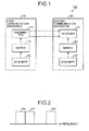
- FIG. 1 is a block diagram of configuration of a communication system according to a first embodiment.
- a communication system 100 includes a first communication apparatus 110 and a second communication apparatus 120.
- configurations of the first communication apparatus 110 and the second communication apparatus 120 will be described for transmitting data from the first communication apparatus 110 to the second communication apparatus 120. Nonetheless, the first communication apparatus 110 and the second communication apparatus 120 may be configured to transmit data from the second communication apparatus 120 to the first communication apparatus 110.
- the first communication apparatus 110 includes a transmitter 111, an acquirer 112, and a switch 113.
- the transmitter 111 can divide data among multiple communication carriers and transmit the data, and has multiple communication modes, each using a different number of communication carriers for transmission.
- the transmitter 111 has a multi-carrier mode and a single carrier mode, as communication modes.
- the multi-carrier mode is a communication mode in which multiple transmitting communication carriers are used.
- the transmitter 111 divides data among multiple communication carriers and transmits the data.
- the single carrier mode is a communication mode in which a single transmitting communication carrier is used.
- the transmitter 111 transmits data by a single carrier.
- the acquirer 112 acquires information indicating a change in the communication state of the transmitter 111.
- a change in the communication state of the transmitter 111 for example, is a change in the volume of data transmitted by the transmitter 111.
- a change in the communication state of the transmitter 111 may be a change in whether the transmitter 111 has data to transmit.
- the acquirer 112 outputs the acquired information to the switch 113.
- the switch 113 switches the communication mode of the transmitter 111, based on the information acquired by the acquirer 112. For example, if the information output from the acquirer 112 indicates that the volume of data transmitted by the transmitter 111 exceeds a given volume, the switch 113 switches the communication mode of the transmitter 111 to the multi-carrier mode. Further, if the information output from the acquirer 112 indicates that the volume of data transmitted by the transmitter 111 is less than or equal to the given volume, the switch 113 switches the communication mode of the transmitter 111 to the single carrier mode.
- Configuration may be such that if the information output from the acquirer 112 indicates that there is data to be transmitted by the transmitter 111, the switch 113 switches the communication mode of the transmitter 111 to the multi-carrier mode. Further, configuration may be such that if the information output from the acquirer 112 indicates that there is no data to be transmitted by the transmitter 111, the switch 113 switches the communication mode of the transmitter 111 to the single carrier mode.
- the second communication apparatus 120 includes a receiver 121, an acquirer 122, and a switch 123.
- the receiver 121 can receive data that has been divided among multiple communication carriers and transmitted, and has multiple communication modes, each using a different number of communication carriers for reception. For example, the receiver 121 has a multi-carrier mode and a single carrier mode as communication modes.
- the multi-carrier mode is a communication mode in which multiple receiving communication carriers are used.
- the receiver 121 receives data that has been divided among multiple communication carriers and transmitted.
- the single carrier mode is a communication mode in which a single receiving communication carrier is used.
- the receiver 121 receives data by a single carrier.
- the acquirer 122 acquires information indicating a change in the communication state of the receiver 121.
- a change in the communication state of the receiver 121 for example, is a change in the volume of data received by the receiver 121.
- a change in the communication state of the receiver 121 may be a change in whether there is data to be received by the receiver 121.
- the acquirer 122 outputs the acquired information to the switch 123.
- the switch 123 switches the communication mode of the receiver 121, based on the information acquired by the acquirer 122. For example, if the information output from the acquirer 122 indicates that the volume of data received by receiver 121 exceeds a given volume, the switch 123 switches the communication mode of the receiver 121 to the multi-carrier mode. If the information output from the acquirer 122 indicates that the volume of data received by the receiver 121 is less than or equal to the given volume, the switch 123 switches the communication mode of the receiver 121 to the single carrier mode.
- Configuration may be such that if the information output from the acquirer 122 indicates that there is data to be received by the receiver 121, the switch 123 switches the communication mode of the receiver 121 to the multi-carrier mode. In this case, if the information output from the acquirer 122 indicates that there is no data to be received by the receiver 121, the switch 123 switches the communication mode of the receiver 121 to the single carrier mode.
- the transmitter 111 of the first communication apparatus 110 is implemented by, for example, a wireless communication interface such as an antenna and communication control circuit.
- the acquirer 112 of the first communication apparatus 110 is implemented by, for example, an information processor such as a digital signal processor (DSP).
- the acquirer 112 stores the acquired information to a memory of the first communication apparatus 110.
- the switch 113 of the first communication apparatus 110 is implemented by, for example, an information processor such as a DSP.
- the switch 113 reads out the information stored to the memory by the acquirer 112 and based on the read information, switches the communication mode.
- the receiver 121 of the second communication apparatus 120 is implemented by, for example, a wireless communication interface such as an antenna and communication control circuit.
- the acquirer 122 of the second communication apparatus 120 is implemented by, for example an information processor such as a DSP.
- the acquirer 122 stores the acquired information to a memory of the second communication apparatus 120.
- the switch 123 of the second communication apparatus 120 is implemented by, for example, an information processor such as a DSP. The switch 123 reads out the information stored to the memory by the acquirer 122 and based on the read information, switches the communication mode.
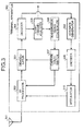
- FIG. 2 is a diagram of communication carriers used in the communication system.
- the horizontal axis represents frequency.
- Communication carriers 201 to 203 each represent system carriers divided by frequency.
- the transmitter 111 of the first communication apparatus 110 When in the multi-carrier mode, the transmitter 111 of the first communication apparatus 110, for example, divides data among the communication carriers 201 to 203 and transmits the data. Further, when in the single carrier mode, the transmitter 111 of the first communication apparatus 110 transmits data by the communication carrier 201.
- the receiver 121 of the second communication apparatus 120 When in the multi-carrier mode, the receiver 121 of the second communication apparatus 120, for example, receives data that has been divided among the communication carriers 201 to 203 and transmitted. Further, when the transmitter 111 of the first communication apparatus 110 is in the single carrier mode, for example, the receiver 121 receives data transmitted by the communication carrier 201.
- the communication system 100 of the first embodiment switches between communication modes of differing component carrier counts. Consequently, when the volume of data to be transmitted is great, a communication mode of a large number of component carriers (e.g., the multi-carrier mode) is switched to, whereby communication of high throughput can be performed.
- a communication mode of a large number of component carriers e.g., the multi-carrier mode
- a communication mode of a small number of component carriers (e.g., the single carrier mode) is switched to, whereby power consumption of the first communication apparatus 110 and the second communication apparatus 120 can be suppressed.
- a communication mode of a small number of component carriers e.g., the single carrier mode
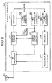
- FIG. 3 is a block diagram of a configuration of a terminal apparatus according to a second embodiment.
- a terminal apparatus 300 according to the second embodiment includes an antenna 301, an RF processor 302, a demodulator 303, a decoder 304, a logic channel analyzer 305, a transmission timing controller 306, a carrier count switch 307, an ACK/NACK generator 308, an encoder 309, and a modulator 310.
- the terminal apparatus 300 corresponds to, for example, the second communication apparatus 120 depicted in FIG. 1 . Further, the terminal apparatus 300, for example, is a terminal apparatus that is compliant with LTE-Advanced.
- the terminal apparatus 300 can receive data that has been divided among multiple component carriers (communication carriers) and transmitted, and has multiple communication modes, each using a different number of communication carriers. For example, as communication modes, the terminal apparatus 300 has the multi-carrier mode in which multiple receiving communication carriers are used and the single carrier mode in which a single receiving communication carrier is used.
- the antenna 301 is an antenna for performing wireless communication with a base station apparatus (e.g., a base station apparatus 400 depicted in FIG. 4 ).
- a base station apparatus e.g., a base station apparatus 400 depicted in FIG. 4 .
- the antenna 301 receives a signal transmitted by the base station apparatus and outputs the signal to the RF processor 302.
- the antenna 301 further transmits to the base station apparatus, a delivery confirmation signal (ACK or NACK) output from the RF processor 302.
- ACK or NACK delivery confirmation signal
- the RF processor 302 converts the frequency of the signal output from the antenna 301, from a high frequency wave (radio frequency (RF)) to a baseband, and outputs the frequency converted signal to the demodulator 303.
- the RF processor 302 further converts the frequency of the delivery confirmation signal output from the modulator 310, from a baseband to a high frequency wave, and outputs the frequency converted delivery confirmation signal to the antenna 301.
- the demodulator 303 demodulates the signal output from the RF processor 302 and outputs the demodulated signal to the decoder 304.
- the decoder 304 decodes the signal output from the demodulator 303 and outputs the data resulting from the decoding, to the logic channel analyzer 305. For example, the decoder 304 performs signal error correction and decoding (forward error correction (FEC)) and notifies the ACK/NACK generator 308 of the results.
- FEC forward error correction
- the logic channel analyzer 305 performs logic channel analysis on the data output from the decoder 304. For example, the logic channel analyzer 305 acquires binary data included in the data and outputs the acquired binary data downstream. Binary data is, for example, user data transmitted by the base station apparatus. The logic channel analyzer 305 further acquires, as information indicating changes in communication state, a timing command included in the data.
- the logic channel analyzer 305 detects an ID representing a timing command and acquires the timing command from the area corresponding to the detected ID.
- a timing command is a command indicating the timing at which the terminal apparatus 300 is to transmit the data to the base station apparatus.
- a timing command is indicated by a difference from the previous transmission timing of the terminal apparatus 300.
- a valid period is set for the timing command.
- the length of the valid period is set by the base station apparatus when the terminal apparatus 300 first connects to the base station apparatus.
- the logic channel analyzer 305 outputs the acquired timing command to the transmission timing controller 306.
- the transmission timing controller 306 based on the timing command output from the logic channel analyzer 305, controls the transmission timing of data (user data) transmitted by the terminal apparatus 300. However, in FIG. 3 , configuration for transmitting data from the terminal apparatus 300 is omitted.
- the transmission timing controller 306 notifies the carrier count switch 307 of the acquisition of the timing command.
- the carrier count switch 307 has a function of a synchronous timer that times the valid period of the timing command. Upon being notified, by the transmission timing controller 306, of the acquisition of the timing command, the carrier count switch 307 starts timing the valid period by the synchronous timer. The carrier count switch 307, based on the valid period of the timing command timed by the synchronous timer, switches the communication mode of the terminal apparatus 300.
- the carrier count switch 307 sets the communication mode to the multi-carrier mode during the valid period of the timing command. Outside the valid period of the timing command, the carrier count switch 307 sets the communication mode to the single carrier mode.
- the carrier count switch 307 sets the communication mode to the multi-carrier mode by setting the RF processor 302 and the demodulator 303 to perform reception operations by multiple component carriers.
- the carrier count switch 307 further sets the communication mode to the single carrier mode by setting the RF processor 302 and the demodulator 303 to perform reception operations by a single component carrier.
- the ACK/NACK generator 308 generates a delivery confirmation signal, based on the error correction and decoding results from the decoder 304. For example, the ACK/NACK generator 308 generates an ACK signal when the decoder 304 reports no errors or successful correction of errors and generates a NACK signal when the decoder 304 reports failure to correct errors. The ACK/NACK generator 308 outputs the generated delivery confirmation signal to the encoder 309.
- the encoder 309 encodes the delivery confirmation signal output from the ACK/NACK generator 308.
- the encoder 309 outputs the encoded delivery confirmation signal to the modulator 310.
- the modulator 310 modulates the delivery confirmation signal output from the encoder 309 and outputs the modulated delivery confirmation signal to the RF processor 302.
- FIG. 4 is a block diagram of a configuration of the base station apparatus according to the second embodiment.
- the base station apparatus 400 according to the second embodiment includes a scheduler 401, a transmission timing controller 402, a binary data buffer 403, an encoder 404, a modulator 405, an RF processor 406, an antenna 407, a demodulator 408, an ACK/NACK determiner 409, and a carrier count switch 410.
- the base station apparatus 400 corresponds to the first communication apparatus 110 depicted in FIG. 1 .
- the base station apparatus 400 is, for example, a base station apparatus that is compliant with LTE-Advanced.
- the base station apparatus 400 can divide data among multiple component carriers (communication carriers) and transmit the data, and has multiple communication modes, each using a different number of communication carriers for transmission. For example, as communication modes, the base station apparatus 400 has the multi-carrier mode in which multiple transmitting communication carriers are used and the single carrier mode in which a single transmitting communication carrier is used.
- the scheduler 401, the transmission timing controller 402, the encoder 404, the modulator 405, the RF processor 406, and the antenna 407 correspond to, for example, the transmitter 111 depicted in FIG. 1 .
- the demodulator 408 and the ACK/NACK determiner 409 correspond to, for example, the acquirer 112 depicted in FIG. 1 .
- the carrier count switch 410 corresponds to, for example, the switch 113 depicted in FIG. 1 .
- the scheduler 401 schedules communication between the terminal apparatus 300 and the base station apparatus 400. For example, the scheduler 401 determines the bit count of the data transmitted by the base station apparatus 400 to each terminal apparatus. The scheduler 401, based on the communication mode of the base station apparatus 400 set by the carrier count switch 410, further determines the component carrier to be used for each communication.
- the scheduler 401 when the multi-carrier mode is set by the carrier count switch 410, the scheduler 401 performs scheduling such that multiple component carriers are used to transmit data. Further, when the single carrier mode is set by the carrier count switch 410, the scheduler 401 performs scheduling such that a single component carrier is used to transmit data.
- the scheduler 401 notifies the transmission timing controller 402 and the modulator 405 of the scheduling results.
- the scheduler 401 based on the scheduling results, further outputs to the binary data buffer 403, an instruction to output data.
- the binary data buffer 403 stores therein data (binary data) for transmissions to the terminal apparatus 300. Upon output of an output instruction from the scheduler 401, the binary data buffer 403 outputs the stored data to the encoder 404.
- the transmission timing controller 402 based on the scheduling results from the scheduler 401, generates a timing command that indicates the timing at which the terminal apparatus 300 is to transmit a delivery confirmation signal in response to the data transmitted by the base station apparatus 400.
- the transmission timing controller 402 outputs the generated timing command to the encoder 404.
- the encoder 404 stores the timing command output from the transmission timing controller 402 to the data output from the binary data buffer 403.
- the encoder 404 encodes the data to which the timing command has been stored and outputs the encoded data to the modulator 405.
- the modulator 405 modulates the data output from the encoder 404 and outputs to the RF processor 406, the signal obtained by the encoding.
- the modulator 405 modulates the data by communication resources (physical resources) corresponding to the component carriers indicated by the scheduling results from the scheduler 401. For example, upon notification that data is to be divided among multiple component carriers and transmitted, the modulator 405 performs data modulation by communication resources corresponding the component carriers. Upon receiving notification that data is to be transmitted by a single component carrier, the modulator 405, performs data modulation by the communication resource corresponding to the component carrier.
- the RF processor 406 converts the frequency of the signal output from the modulator 405, from a baseband to a high frequency wave, and outputs the frequency converted signal to the antenna 407.
- the RF processor 406 further converts the frequency of a delivery confirmation signal output from the antenna 407, from a high frequency wave to a baseband, and outputs the frequency converted delivery confirmation signal to the demodulator 408.
- the antenna 407 is an antenna for performing wireless communication with the terminal apparatus 300.
- the antenna 407 receives a delivery confirmation signal transmitted by the terminal apparatus 300 and outputs the received delivery confirmation signal to the RF processor 406.
- the antenna 407 further transmits to the terminal apparatus 300, the signal output from the RF processor 406.
- the demodulator 408 demodulates the delivery confirmation signal output from the RF processor 406 and outputs the demodulated delivery confirmation signal to the ACK/NACK determiner 409.
- the ACK/NACK determiner 409 judges the delivery confirmation signal output from the demodulator 408. For example, the ACK/NACK determiner 409 determines whether the delivery confirmation signal is in response to any one of the signals, and determines whether the delivery confirmation signal is any one of an ACK signal and a NACK signal. The ACK/NACK determiner 409 notifies the carrier count switch 410 of the results of determination.
- the carrier count switch 410 switches the communication mode of the base station apparatus 400, based on the determination results from the ACK/NACK determiner 409. For example, when the determination results from the ACK/NACK determiner 409 indicate that an ACK signal has been received in response to the timing command, the carrier count switch 410 switches the communication mode to the multi-carrier mode.
- the carrier count switch 410 has a synchronous timer function that times the valid period of the timing command transmitted by the base station apparatus 400 to the terminal apparatus 300. Based on the synchronous timer, the carrier count switch 410 switches the communication mode to the single carrier mode, when the time is outside the valid period of the timing command.
- the carrier count switch 410 sets the scheduler 401 to perform scheduling for multiple component carriers, and thereby sets the communication mode of the base station apparatus 400 to the multi-carrier mode.
- the carrier count switch 410 sets the scheduler 401 to perform scheduling for a single component carrier, and thereby sets the communication mode of the base station apparatus 400 to the single carrier mode.
- FIG. 5 is a flowchart of an example of operations of the terminal apparatus according to the second embodiment.
- the terminal apparatus 300 (see FIG. 3 ), for example, performs the following operations.
- the carrier count switch 307 determines whether a timing command from the base station apparatus 400 has been received (step S501). If a timing command has not been received (step S501: NO), the flow proceeds to step S504.
- step S501 if a timing command has been received (step S501: YES), the carrier count switch 307 starts operation of the synchronous timer that times the valid period of the timing command (step S502).
- the carrier count switch 307 switches the communication mode of the terminal apparatus 300 to the multi-carrier mode (step S503).
- the carrier count switch 307 determines whether the synchronous timer started at step S502 has expired (step S504).
- step S504 if the synchronous timer has not expired (step S504: NO), the flow returns to step S501 and processes therefrom are continued. If the synchronous timer has expired (step S504: YES), the carrier count switch 307 switches the communication mode of the terminal apparatus 300 to the single carrier mode (step S505), the flow returns to step S501 and operations therefrom are continued. By performing the above operations, the terminal apparatus 300 can switch the communication mode, based on the valid period of an acquired timing command.
- FIG. 6 is a flowchart of an example of operations of the base station apparatus according to the second embodiment.
- the base station apparatus 400 (see FIG. 4 ), for example, performs the following operations.
- the ACK/NACK determiner 409 determines whether an ACK signal has been received in response to a timing command transmitted to the terminal apparatus 300 (step S601). If an ACK signal has not been received (step S601: NO), the flow proceeds to step S604.
- step S601 if an ACK signal has been received in response to the timing command (step S601: YES), the carrier count switch 410 starts operation of the synchronous timer that times the valid period of the timing command (step S602).
- the carrier count switch 410 switches the communication mode to the multi-carrier mode (step S603).
- the carrier count switch 410 determines whether the period of the synchronous timer started at step S602 has expired (step S604).
- step S604 if the timer of the synchronous timer has not expired (step S604: NO), the flow returns to step S601 and processes therefrom are continued. If the period of the synchronous timer has expired (step S604: YES), the carrier count switch 410 switches the communication mode to the single carrier mode (step S605); the flow returns to step S601 and the operations therefrom are continued.
- the base station apparatus 400 can switch the communication mode, based on an acquired delivery confirmation signal that is from the terminal apparatus 300 and in response to the timing command transmitted to the terminal apparatus 300.
- FIG. 7 is a sequence diagram of an example of operations of the communication system according to the second embodiment.
- the base station apparatus 400 transmits a timing command to the terminal apparatus 300 (step S702).
- Period t1 represents the valid period of the timing command transmitted at step S702.
- the base station apparatus 400 transmits to the terminal apparatus 300, a portion of the transmission data at step S701 (step S703).
- the terminal apparatus 300 transmits an ACK signal to the base station apparatus 400, in response to the data transmitted at step S703 (step S704).
- the base station apparatus 400 transmits a timing command to the terminal apparatus 300 (step S705).
- Period t2 represents the valid period of the timing command transmitted at step S705.
- the base station apparatus 400 transmits to the terminal apparatus 300, a portion of the transmission data at step S701 (step S706).
- the terminal apparatus 300 transmits an ACK signal to the base station apparatus 400, in response to the data transmitted at step S706 (step S707).
- step S707 it is assumed that all of the transmission data at step S701 has been received by the terminal apparatus 300 through the steps above.
- the base station apparatus 400 terminates the transmission process (step S708), ending the series of operations.
- the communication modes of the terminal apparatus 300 and the base station apparatus 400 are set as the multi-carrier mode during period T when at least one of the periods t1 and t2 is being timed. Further, during periods outside the period T, the terminal apparatus 300 and the base station apparatus 400 are in the single carrier mode.
- step S703 and step S706 an example where the data transmitted at step S703 and step S706 is properly received by the terminal apparatus 300 and an ACK signal is transmitted by the terminal apparatus 300 to the base station apparatus 400 has been described.
- the base station apparatus 400 again transmits the data to the terminal apparatus 300.
- the timing of period t1 begins when an ACK signal (not depicted) that is from the terminal apparatus 300 and in response to the transmitted timing command is received.
- the communication mode of the base station apparatus 400 may be switched to the multi-carrier mode.
- the base station apparatus 400 periodically transmits a timing command to the terminal apparatus 300 during the data transmission process, whereby during the data transmission process, the terminal apparatus 300 and the base station apparatus 400 are switched to the multi-carrier mode, enabling communication of high throughput to be performed.
- the base station apparatus 400 Upon completing the data transmission process, the base station apparatus 400 suspends the transmission of the timing command. Consequently, after the data transmission process, the valid period of the timing command expires and the terminal apparatus 300 and the base station apparatus 400 are switched to the single carrier mode, thereby enabling power consumption of the terminal apparatus 300 and the base station apparatus 400 to be suppressed.
- the terminal apparatus 300 acquires, as information indicating a change in the communication state, a timing command that indicates the timing at which the terminal apparatus 300 is to transmit a signal.
- the timing command for example, is a timing command that indicates the timing at which the terminal apparatus 300 is to transmit a delivery confirmation signal in response to data received by the terminal apparatus 300.
- the terminal apparatus 300 switches the communication mode, based on the valid period of the acquired timing command. Since an existing timing command can be used as information indicating a change in the communication state, communication resources can be used efficiently without new control information being communicated to/from the base station apparatus 400.
- the terminal apparatus 300 switches to the multi-carrier mode during the valid period of the timing command, enabling communication of high throughput to be performed.
- the terminal apparatus 300 switches to the single carrier mode during periods outside the valid period of the timing command, thereby enabling power consumption to be suppressed.
- the base station apparatus 400 acquires, as information indicating a change in the communication state, a delivery confirmation signal that is from the terminal apparatus 300 and in response to a timing command transmitted to the terminal apparatus 300; and based on the delivery confirmation signal, switches the communication mode. Since an existing timing command can be used as information indicating a change in the communication state, communication resources can be used efficiently without new control information being communicated to/from the terminal apparatus 300.
- the base station apparatus 400 switches to the multi-carrier mode during the valid period of the timing command and to the single carrier mode outside the valid period of the timing command. Consequently, since the communication mode is switched after confirmation of the timing command being properly received by the terminal apparatus 300, the communication mode of the base station apparatus 400 can be switched in conjunction with the switching of communication modes by the terminal apparatus 300.
- the base station apparatus 400 For communication in which a delivery confirmation signal is not communicated, the base station apparatus 400 does not transmit to the terminal apparatus 300, a timing command for the transmission of a delivery confirmation signal and therefore, the communication modes of the terminal apparatus 300 and the base station apparatus 400 are the single carrier mode.
- the volume of data is often small and thus, in this case, sufficient throughput can be achieve by the single carrier mode and power consumption can be suppressed.
- PCCH paging control channels
- BCCH broadcast control channels
- the data rate is low.
- PCCHs and BCCHs since the communication mode remains as the single carrier mode, sufficient throughput can be achieved and power consumption can be suppressed.
- the timing command may be a timing command that indicates the timing at which the terminal apparatus 300 is to transmit data (user data) to the base station apparatus 400. For example, when there is data to be transmitted to the base station apparatus 400, the terminal apparatus 300 accesses the base station apparatus 400 by random access and acquires from the base station apparatus 400, a timing command for the transmission of data.
- the base station apparatus 400 switches the communication mode, based on the acquired valid period of the timing command, thereby enabling efficient use of communication resources.
- the number of component carriers used in the multi-carrier mode may differ for downlinks from the base station apparatus 400 to the terminal apparatus 300 and uplinks from the terminal apparatus 300 to the base station apparatus 400.
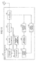
- FIG. 8 is a block diagram of configuration of the terminal apparatus according to a third embodiment.
- the terminal apparatus 300 according to the third embodiment includes an RRC information analyzer 801 and an RRC completion signal generator 802 in place of the transmission timing controller 306 and the ACK/NACK generator 308 in the configuration depicted in FIG. 3 .
- the decoder 304 outputs error correction and decoding results to the RRC completion signal generator 802.
- the logic channel analyzer 305 acquires a radio resource control (RRC) message included in the data output from the decoder 304.
- the logic channel analyzer 305 outputs the acquired RRC message to the RRC information analyzer 801.
- RRC radio resource control
- the RRC information analyzer 801 detects DRX (discontinuous reception) information, from the RRC message output from the logic channel analyzer 305.
- the DRX information includes a DRX setting signal requesting the terminal apparatus 300 to set a DRX cycle and a DRX cancellation signal requesting the terminal apparatus 300 to cancel the set DRX cycle.
- the RRC information analyzer 801 outputs the detected DRX information to the demodulator 303 and the carrier count switch 307.
- the demodulator 303 performs discontinuous reception, based on the DRX information output from the RRC information analyzer 801. For example, when a DRX setting signal is output from the RRC information analyzer 801, the demodulator 303 sets the DRX cycle and performs discontinuous reception, based on DRX setting signal. When a DRX cancellation signal is output from the RRC information analyzer 801, the demodulator 303 cancels the DRX cycle and terminates discontinuous reception.
- the carrier count switch 307 switches the communication mode, based on the DRX information output from the RRC information analyzer 801. For example, when a DRX setting signal is output from the RRC information analyzer 801, the carrier count switch 307 switches the communication mode of the terminal apparatus 300 to the multi-carrier mode. When a DRX cancellation signal is output from the RRC information analyzer 801, the demodulator 303 switches the communication mode of the terminal apparatus 300 to the single carrier mode.
- the RRC completion signal generator 802 generates an RRC completion signal, based on the error correction and decoding results from the decoder 304. For example, the RRC completion signal generator 802 generates an RRC completion signal when the decoder 304 reports successful correction of errors. The RRC completion signal generator 802 outputs the generated RRC completion signal to the encoder 309.
- the encoder 309 encodes the RRC completion signal output from the RRC completion signal generator 802.
- the encoder 309 outputs the encoded RRC completion signal to the modulator 310.
- the modulator 310 modulates the RRC completion signal output from the encoder 309.
- the modulator 310 outputs the modulated RRC completion signal to the RF processor 302.
- the RF processor 302 converts the frequency of the RRC completion signal output from the modulator 310, from a baseband to a high frequency wave, and outputs the frequency converted RRC completion signal to the antenna 301.
- the antenna 301 transmits to the base station apparatus 400, the RRC completion signal output from the RF processor 302.
- FIG. 9 is a block diagram of a configuration of the base station apparatus according to the third embodiment.
- the base station apparatus 400 according to the third embodiment includes a DRX cycle setting controller 901, a decoder 902, and an RRC completion signal determiner 903 in place of the transmission timing controller 402 and the ACK/NACK determiner 409 in the configuration depicted in FIG. 4 .
- the scheduler 401 in performing scheduling, decides whether to set or cancel the DRX cycle of the terminal apparatus 300. For example, when there is little or no data to be transmitted to the terminal apparatus 300, the scheduler 401 decides to set a DRX cycle for the terminal apparatus 300. When the volume of data to be transmitted to the terminal apparatus 300 is great, the scheduler 401 decides to cancel the DRX cycle set for the terminal apparatus 300.
- the scheduler 401 notifies the DRX cycle setting controller 901 and the modulator 405 of the scheduling results.
- the DRX cycle setting controller 901 generates DRX information, based on the scheduling results from the scheduler 401.
- DRX information is, for example, a setting signal requesting the terminal apparatus 300 to set a DRX cycle, or a cancellation signal requesting the terminal apparatus 300 to cancel the set DRX cycle.
- the DRX cycle setting controller 901 outputs to the encoder 404, an RRC message that includes the generated DRX information.
- the encoder 404 stores the RRC message output from the DRX cycle setting controller 901 to data output from the binary data buffer 403.
- the encoder 404 encodes the data to which the RRC has been stored and outputs the encoded data to the modulator 405.
- the antenna 407 receives an RRC completion signal transmitted by the terminal apparatus 300 and outputs the RRC completion signal to the RF processor 406.
- the RF processor 406 converts the frequency of the RRC completion signal output from the antenna 407, from a high frequency wave to a baseband, and outputs the frequency converted RRC completion signal to the demodulator 408.
- the demodulator 408 demodulates the RRC completion signal output from the RF processor 406 and outputs the demodulated RRC completion signal to the decoder 902.
- the decoder 902 decodes the RRC completion signal output from the demodulator 408.
- the decoder 902 outputs the decoded RRC completion signal to the RRC completion signal determiner 903.
- the RRC completion signal determiner 903 makes a determination about the RRC completion signal output from the decoder 902. For example, the RRC completion signal determiner 903 determines whether the RRC completion signal is an RRC completion signal that is in response to a DRX setting signal, or an RRC completion signal that is in response to a DRX cancellation signal.
- the RRC completion signal determiner 903 notifies the carrier count switch 410 of the determination results.
- the carrier count switch 410 switches the communication mode of the base station apparatus 400, based on the determination results from the RRC completion signal determiner 903. For example, when the RRC completion signal determiner 903 reports acquisition of an RRC completion signal that is in response to a DRX setting signal, the carrier count switch 410 switches the communication mode to the single carrier mode. When the RRC completion signal determiner 903 reports the acquisition of an RRC completion signal that is in response to a DRX cancellation signal, the carrier count switch 410 switches the communication mode to the multi-carrier mode.
- FIG. 10 is a flowchart of an example of operations of the terminal apparatus according to the third embodiment.
- the terminal apparatus 300 (see FIG. 8 ), for example, performs the following operations.
- the carrier count switch 307 determines whether a DRX setting signal from the base station apparatus 400 has been received (step S1001). If a DRX setting signal has not been received (step S1001: NO), the flow proceeds to step S1003.
- step S1001 if a DRX setting signal from the base station apparatus 400 has been received (step S1001: YES), the carrier count switch 307 switches the communication mode of the terminal apparatus 300 to the multi-carrier mode (step S1002). Subsequently, the carrier count switch 307 determines whether a DRX cancellation signal from the base station apparatus 400 has been received (step S1003).
- step S1003 if a DRX cancellation signal has not been received (step S1003: NO), the flow returns to step S1001 and the operations therefrom are continued. If a DRX cancellation signal has been received (step S1003: YES), the carrier count switch 307 switches the communication mode of the terminal apparatus 300 to the single carrier mode (step S1004), the flow returns to step S1001 and the operations therefrom are continued. By performing the operations above, the terminal apparatus 300 can switch the communication mode, based on the acquired setting signal and cancellation signal.
- FIG. 11 is a flowchart of an example of operations of the base station apparatus according to the third embodiment.
- the base station apparatus 400 (see FIG. 9 ), for example, performs the following operations.
- the RRC completion signal determiner 903 determines whether an RRC completion signal has been received in response to the DRX setting signal transmitted to the terminal apparatus 300 (step S1101). If an RRC completion signal has not been received in response to the DRX setting signal (step S1101: NO), the flow proceeds to step S1103.
- step S1101 if an RRC completion signal has been received in response to the DRX setting signal (step S1101: YES), the carrier count switch 410 switches the communication mode of the base station apparatus 400 to the single carrier mode (step S1102). Subsequently, the RRC completion signal determiner 903 determines whether an RRC completion signal has been received in response to the DRX cancellation signal transmitted to the terminal apparatus 300 (step S1103).
- step S1103 if an RRC completion signal has not been received in response to the DRX cancellation signal (step S1103: NO), the flow returns to step S1101 and the operations therefrom are continued. If an RRC completion signal has been received in response to the DRX cancellation signal (step S1103: YES), the carrier count switch 410 switches the communication mode of the base station apparatus 400 to the multi-carrier mode (step S1104), and the flow returns to step S1101 and the operations therefrom are continued. By performing the operations above, the base station apparatus 400 can switch the communication mode, based on an RRC completion signal that is in response to the DRX setting signal and the DRX cancellation signal.
- the terminal apparatus 300 acquires a DRX setting signal requesting the terminal apparatus 300 to set a DRX cycle and a DRX cancellation signal requesting the terminal apparatus 300 to cancel the set DRX cycle.
- the terminal apparatus 300 switches the communication mode, based on the acquired DRX setting signal and DRX cancellation signal.
- the terminal apparatus 300 since the possibility of data being transmitted from the base station apparatus 400 is high when the DRX cycle is cancelled, upon receiving a DRX cancellation signal, the terminal apparatus 300 switches to the multi-carrier mode, thereby enabling communication of high throughput to be performed. Further, since the possibility of data being transmitted from the base station apparatus 400 is low when the DRX cycle is set, upon receiving a DRX setting signal, the terminal apparatus 300 switches to the single carrier mode, enabling power consumption to be suppressed.
- the base station apparatus 400 acquires an RRC completion signal that is from the terminal apparatus 300 and in response to a DRX setting signal or a DRX cancellation signal transmitted to the terminal apparatus 300; and based on the acquired RRC completion signal, the base station apparatus 400 switches the communication mode. Consequently, since an existing RRC completion signal can be used as information indicating a change in the communication state, communication resources can be used efficiently without new control information being communicated to/from the terminal apparatus 300.
- the base station apparatus 400 switches to the multi-carrier mode.
- the base station apparatus 400 switches to the single carrier mode. Consequently, since the communication mode is switched after confirmation of the DRX cancellation signal (or the DRX setting signal) being properly received by the terminal apparatus 300, the communication mode of the base station apparatus 400 can be switched in conjunction with the switching of communication modes by the terminal apparatus 300.
- FIG. 12 is a block diagram of a configuration of the terminal apparatus according to a fourth embodiment.
- the terminal apparatus 300 according to the fourth embodiment includes a data channel decoder 1201, a control channel decoder 1202, and a binary data buffer 1203 in place of the decoder 304, the logic channel analyzer 305, and the transmission timing controller 306 in the configuration depicted in FIG. 3 .
- the demodulator 303 outputs demodulated data to the channel decoder 1201 and the control channel decoder 1202.
- the data channel decoder 1201 based on reception allocation information output from the control channel decoder 1202, decodes a data channel included in the signal output from the demodulator 303.
- the data channel decoder 1201 performs error correction and decoding on the signal and notifies the ACK/NACK generator 308 of the results of the error correction and decoding.
- the data channel decoder 1201 further outputs the decoded data downstream.
- the control channel decoder 1202 decodes a control channel included in the signal output from the demodulator 303.
- the control channel included in the signal output from the demodulator 303 includes information that indicates the communication resources allocated to the terminal apparatus 300.
- Allocation information is, for example, reception allocation information that indicates the communication resources allocated for data reception, by the terminal apparatus 300; or transmission allocation information that indicates the communication resources allocated for data transmission, by the terminal apparatus 300.
- the control channel decoder 1202 acquires, as information indicating a change in the communication state, the reception allocation information and the transmission allocation information included in the control channel. Upon acquiring reception allocation information, the control channel decoder 1202 outputs the acquired reception allocation information to the data channel decoder 1201 and notifies the carrier count switch 307 of the acquisition of the reception allocation information. Upon acquiring transmission allocation information, the control channel decoder 1202 notifies the carrier count switch 307 of the acquisition of the transmission allocation information.
- the control channel decoder 1202 Upon acquiring transmission allocation information, the control channel decoder 1202 outputs to the binary data buffer 1203, an output instruction instructing the output of data of a volume corresponding to the communication resources indicated by the transmission allocation information.
- the binary data buffer 1203 stores therein data (user data) for transmissions to the base station apparatus 400.
- the binary data buffer 1203 outputs to the encoder 309 and according to the volume indicated by the output instruction, a portion of the data stored therein.
- the carrier count switch 307 switches the communication mode of the terminal apparatus 300, based on the notification of the acquisition of reception allocation information or transmission allocation information by the control channel decoder 1202. For example, upon notification of the acquisition of reception allocation information or transmission allocation information from the control channel decoder 1202, the carrier count switch 307 sets the communication mode to the multi-carrier mode.
- the carrier count switch 307 has a function of a timer that times a given period (e.g., of a few seconds) that starts upon notification of the acquisition of reception allocation information or transmission allocation information from the control channel decoder 1202.
- a given period e.g., of a few seconds
- the carrier count switch 307 sets the communication mode to the single carrier mode.
- the carrier count switch 307 may reset the timer. In this case, the carrier count switch 307 sets the communication mode to the single carrier mode upon the elapse of the given period after the resetting of the timer.
- the ACK/NACK generator 308 generates a delivery confirmation signal, based on the error correction and decoding results from the data channel decoder 1201.
- the encoder 309 encodes the delivery confirmation signal output from the ACK/NACK generator 308 and outputs the encoded delivery confirmation signal to the modulator 310.
- the encoder 309 further encodes the data output from the binary data buffer 1203 and outputs the encoded data to the modulator 310.
- the modulator 310 modulates the data output from the encoder 309 and outputs the modulated data to the RF processor 302.
- the antenna 301 transmits to the base station apparatus 400, the delivery confirmation signal and data output from the RF processor 302.
- the RF processor 302 converts the frequency of the delivery confirmation signal and data output from the modulator 310, from a baseband to a high frequency wave, and outputs the frequency converted delivery confirmation signal and data to the antenna 301.
- FIG. 13 is a block diagram of a configuration of the base station apparatus according to the fourth embodiment.
- the base station apparatus 400 according to the fourth embodiment includes a control signal generator 1301, an ACK/NACK demodulator 1302, and a data demodulator 1303 in place of the transmission timing controller 402 and the demodulator 408 in the configuration depicted in FIG. 4 .
- the scheduler 401 notifies the control signal generator 1301 and the modulator 405 of the scheduling results.
- the control signal generator 1301 generates a control signal, based on the scheduling results from the scheduler 401. For example, the control signal generator 1301 generates reception allocation information, which indicates the communication resources allocated for data reception, by the terminal apparatus 300.
- the control signal generator 1301 further generates transmission allocation information, which indicates the communication resources allocated for data transmission, by the terminal apparatus 300.
- the scheduler 401 outputs the generated control signal to the encoder 404, as a control channel.
- the encoder 404 encodes the control channel output from the transmission timing controller 402 and outputs the encoded data to the modulator 405.
- the modulator 405 modulates the control channel output from the encoder 404.
- the RF processor 406 converts the frequency of the delivery confirmation signal output from the antenna 407, from a high frequency wave to a baseband, and outputs the frequency converted delivery confirmation signal to the ACK/NACK demodulator 1302 and the data demodulator 1303.
- the antenna 407 receives a signal transmitted by the terminal apparatus 300 and outputs the signal to the RF processor 406.
- the ACK/NACK demodulator 1302 demodulates the delivery confirmation signal included in the signal output from the RF processor 406 and outputs the demodulated delivery confirmation signal to the ACK/NACK determiner 409.
- the data demodulator 1303 demodulates the data included in the signal output from the RF processor 406 and outputs the demodulated data to the carrier count switch 410.
- the carrier count switch 410 switches the communication mode of the base station apparatus 400, based on determination results from the ACK/NACK determiner 409 and the data output from the data demodulator 1303.
- the carrier count switch 410 switches the communication mode to the multi-carrier mode. Further, when data transmitted by the terminal apparatus 300 is output from the data demodulator 1303, the carrier count switch 410 switches the communication mode to the multi-carrier mode.
- the carrier count switch 410 has a function of a timer that times a given period that starts upon the switching of the communication mode to the multi-carrier mode. When the given period, which starts upon the switching of the communication mode to the multi-carrier mode, has elapsed according to the timer, the carrier count switch 410 switches the communication mode to the single carrier mode.
- FIG. 14 is a flowchart of an example of operations of the terminal apparatus according to the fourth embodiment.
- the terminal apparatus 300 (see FIG. 12 ), for example, performs the following operations.
- the carrier count switch 307 determines whether allocation information (reception allocation information or transmission allocation information) from the base station apparatus 400 has been received (step S1401).
- step S1401 if allocation information (reception allocation information or transmission allocation information) has not been received (step S1401: NO), the flow proceeds to step S1404. If allocation information (reception allocation information or transmission allocation information) from the base station apparatus 400 has been received (step S1401: YES), the carrier count switch 307 starts operation of the timer, which times the given period (step S1402). The carrier count switch 307 switches the communication mode of the terminal apparatus 300 to the multi-carrier mode (step S1403).
- the carrier count switch 307 determines whether the period of the timer started at step S1402 has expired (step S1404). If the period of the timer has not expired (step S1404: NO), the flow returns to step S1401 and the operations therefrom are continued. If the period of the timer has expired (step S1404: YES), the carrier count switch 307 switches the communication mode of the terminal apparatus 300 to the single carrier mode (step S1405); the flow returns to step S1401 and the operations therefrom are continued. By performing the operations above, the terminal apparatus 300 can switch the communication mode, based on allocation information indicating the communication resources that have been allocated to the terminal apparatus 300.
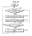
- FIG. 15 is a flowchart of an example of operations of the base station apparatus according to the fourth embodiment.
- the base station apparatus 400 (see FIG. 13 ), for example, performs the following operations.
- the carrier count switch 410 determines if an ACK signal in response to reception allocation information or transmission allocation information transmitted to the terminal apparatus 300, or data transmitted by the terminal apparatus 300 has been received (step S1501).
- step S1501 if neither an ACK signal nor data has been received (step S1501: NO), the flow proceeds to step S1504. If an ACK signal or data has been received (step S1501: YES), the carrier count switch 410 starts operation of the timer, which times the given period (step S1502).
- the carrier count switch 410 switches the communication mode in the scheduler 401 to the multi-carrier mode (step S1503). Subsequently, the carrier count switch 410 determines whether the period of the timer started at the step S1502 has expired (step S1504).
- step S1504 if the period of the timer has not expired (step S1504: NO), the flow returns to step S1501 and the operations therefrom are continued. If the period of the timer has expired (step S1504: YES), the carrier count switch 410 switches the communication mode in the scheduler 401 to the single carrier mode (step S1505); and the flow returns to step S1501 and the operations therefrom are continued.
- the base station apparatus 400 can switch the communication mode, based on the delivery confirmation signal that is in response to reception allocation information or transmission allocation information transmitted to the terminal apparatus 300. Further, the base station apparatus 400 can switch the communication mode, based on data that has been transmitted by the terminal apparatus 300, based on transmission allocation information transmitted to the terminal apparatus 300.
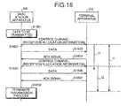
- FIG. 16 is a sequence diagram of an example of operations of the communication system according to the fourth embodiment.
- the base station apparatus 400 transmits a control channel to the terminal apparatus 300 (step S1602).
- the control channel transmitted at step S1602 includes reception allocation information.
- Period t1 represents a given period that starts when the terminal apparatus 300 receives the reception allocation information transmitted at step S1602.
- the base station apparatus 400 transmits to the terminal apparatus 300, a portion of the transmission data at step S1601 (step S1603).
- the terminal apparatus 300 transmits to the base station apparatus 400, an ACK signal in response to the data transmitted at step S1603 (step S1604).
- the base station apparatus 400 transmits a control channel to the terminal apparatus 300 (step S1605).
- the control channel transmitted at step S1605 includes reception allocation information.
- Period t2 represents a given period that starts when the terminal apparatus 300 receives the reception allocation information transmitted at step S1605.
- the base station apparatus 400 transmits to the terminal apparatus 300, data that has not yet been transmitted among the transmission data at step S1601 (step S1606).
- the terminal apparatus 300 transmits to the base station apparatus 400, an ACK signal in response to the data transmitted at step S1606 (step S1607).
- step S1607 it is assumed that all of the transmission data at step S1601 has been received by the terminal apparatus 300 through the steps above.
- the base station apparatus 400 terminates the transmission process (step S1608), ending the series of operations.
- the communication modes of the terminal apparatus 300 and the base station apparatus 400 are set as the multi-carrier mode during period T when at least one of the periods t1 and t2 is being timed. Further, during periods outside the period T, the communication modes of the terminal apparatus 300 and the base station apparatus 400 are sets as the single carrier mode.
- FIG. 16 an example where the data transmitted at step S1603 and step S1606 is properly received by the terminal apparatus 300 and an ACK signal is transmitted by the terminal apparatus 300 to the base station apparatus 400 has been described.
- the base station apparatus 400 again transmits the data to the terminal apparatus 300.
- the timing of period t1 begins when an ACK signal (not depicted) that is from the terminal apparatus 300 and in response to the transmitted control channel is received.
- the communication mode can be switched to the multi-carrier mode.
- configuration may be such that at the base station apparatus 400, the timing of period t1 begins upon the reception (step S1604) of an ACK signal that is from the terminal apparatus 300 and in response to the data transmitted at step S1603.
- the communication mode can be switched to the multi-carrier mode.
- the base station apparatus 400 periodically transmits a control channel to the terminal apparatus 300 during the data transmission process, whereby during the data transmission process, the multi-carrier modes of the terminal apparatus 300 and the base station apparatus 400 can be switched, enabling communication of high throughput to be performed.
- the base station apparatus 400 Upon completing the data transmission process, the base station apparatus 400 suspends the transmission of the control channel. Consequently, after the data transmission process, the valid period of the control channel expires and the terminal apparatus 300 and the base station apparatus 400 are switched to the single carrier mode, thereby enabling power consumption of the terminal apparatus 300 and the base station apparatus 400 to be suppressed.
- the terminal apparatus 300 acquires allocation information (reception allocation information or transmission allocation information) indicating the communication resources allocated to the terminal apparatus 300; and based on the acquired allocation information, the terminal apparatus 300 switches the communication mode. Consequently, since existing allocation information can be used as information indicating a change in the communication state, communication resources can be used efficiently without new control information being communicated to/from the base station apparatus 400.
- the terminal apparatus 300 switches to the multi-carrier mode, thereby enabling communication of high throughput to be performed.
- the possibility of data being transmitted from the terminal apparatus 300 is high and therefore, if transmission allocation information is received, the terminal apparatus 300 switches to the multi-carrier mode, enabling communication of high throughput to be performed.
- the possibility that transmission will be recursively performed at the given period after reception allocation information or transmission allocation information is received, is high. For example, when a webpage is browsed using the terminal apparatus 300, after the designated page is accessed, the possibility that another page will be accessed from a link in the initial page is high.
- the terminal apparatus 300 can switch to the multi-carrier mode at the given period, which begins upon the reception of reception allocation information or transmission allocation information. As a result, communication of high throughput can be performed.
- the terminal apparatus 300 can switch to the single carrier mode upon the elapse of the given period, which begins upon the reception of reception allocation information or transmission allocation information. As a result, power consumption can be suppressed.
- the base station apparatus 400 acquires a delivery confirmation signal that is from the terminal apparatus 300 and in response to allocation information (reception allocation information or transmission allocation information) transmitted to the terminal apparatus 300; and based on the acquired delivery confirmation signal, the base station apparatus 400 switches the communication mode. Consequently, since an existing delivery confirmation signal can be used as information indicating a change in the communication state, communication resources can be used efficiently without new control information being communicated to/from the terminal apparatus 300.
- the base station apparatus 400 switches to the multi-carrier mode. Further, when the given period, which begins upon the acquisition of a delivery confirmation signal that is from the terminal apparatus 300 and in response to allocation information transmitted to the terminal apparatus 300, has elapsed, the base station apparatus 400 switches to the single carrier mode. Consequently, since the communication mode is switched after confirmation of the allocation information being properly received by the terminal apparatus 300, the communication mode of the base station apparatus 400 can be switched in conjunction with the switching of communication modes by the terminal apparatus 300.
- the base station apparatus 400 acquires data that has been transmitted by the terminal apparatus 300, based on transmission allocation information transmitted to the terminal apparatus 300; and based on the acquired data, the base station apparatus 400 switches the communication mode. Consequently, since existing data can be used as information indicating a change in the communication state, communication resources can be used efficiently without new control information being communicated to/from the terminal apparatus 300.
- the base station apparatus 400 switches to the multi-carrier mode. Further, when the given period, which begins upon the acquisition of data that has been transmitted by the terminal apparatus 300, based on allocation information transmitted to the terminal apparatus 300, has elapsed, the base station apparatus 400 switches to the single carrier mode. Consequently, since the communication mode is switched after confirmation of the allocation information being properly received by the terminal apparatus 300, the communication mode of the base station apparatus 400 can be switched in conjunction with the switching of communication modes by the terminal apparatus 300.
- FIG. 17 is a block diagram of a configuration of the terminal apparatus according to a fifth embodiment.
- the terminal apparatus 300 according to the fifth embodiment includes a DRX controller 1701 in addition to the configuration of the terminal apparatus 300 depicted in FIG. 12 .
- the control channel decoder 1202 outputs a decoded control channel to the DRX controller 1701.
- the DRX controller 1701 has a function of a DRX inactivity timer (discontinuous reception inactivity timer) that operates based on the control channel output from the control channel decoder 1202.
- the DRX inactivity timer is a timer that times the DRX inactivity period of the terminal apparatus 300, and for example, is a DRX inactivity timer prescribed under LTE.
- the DRX controller 1701 While the DRX inactivity timer is in operation, the DRX controller 1701 controls the demodulator 303 to inactivate DRX and receive a continuous control channel. When the operation of the DRX inactivity timer ends, the DRX controller 1701 controls the demodulator 303 to perform DRX. The DRX controller 1701 further acquires, as information indicating a change in the communication state, timer information that indicates the operation state of the DRX inactivity timer. The DRX controller 1701 outputs the acquired timer information to the carrier count switch 307.
- the carrier count switch 307 switches the communication mode of the terminal apparatus 300, based on the timer information from the DRX controller 1701. For example, based on the timer information, when the timing of the DRX inactivity period by the DRX inactivity timer of the DRX controller 1701 starts, the carrier count switch 307 switches the communication mode to the multi-carrier mode. Further based on the timer information, when the timing of the DRX inactivity period by the DRX inactivity timer ends, the carrier count switch 307 switches the communication mode to the single carrier mode.
- the base station apparatus 400 may have, for example, the base station apparatus 400 configuration depicted in FIG. 9 .
- the base station apparatus 400 for example, can initiate the operation of the DRX inactivity timer of the terminal apparatus 300 by transmitting a DRX cancellation signal to the terminal apparatus 300.
- FIG. 18 is a flowchart of an example of operations of the terminal apparatus according to the fifth embodiment.
- the terminal apparatus 300 (see FIG. 17 ), for example, performs the following operations.
- the carrier count switch 307 determines whether timing of the DRX inactivity period by the DRX has started (step S1801). If the timing by the DRX inactivity timer has not started (step S1801: NO), the flow proceeds to step S1803.
- step S1801 if the timing by the DRX has started (step S1801: YES), the carrier count switch 307 switches the communication mode of the terminal apparatus 300 to the multi-carrier mode (step S1802). Next, the carrier count switch 307 determines whether the timing of the DRX inactivity period by the DRX inactivity timer has ended (step S1803).
- step S1803 if the timing by the DRX inactivity timer has not ended (step S1803: NO), the flow returns to step S1801 and operations therefrom are performed. If the timing by the DRX inactivity timer has ended (step S1803: YES), the carrier count switch 307 switches the communication mode of the terminal apparatus 300 to the single carrier mode (step S1804); and the flow returns to step S1801 and the operations therefrom are continued. By performing the operations above, the terminal apparatus 300 can switch the communication mode, based on timer information.
- FIG. 19 is a flowchart of an example of operations of the base station apparatus according to the fifth embodiment.
- the base station apparatus 400 according to the fifth embodiment (for example, see FIG. 9 ), for example, performs the following operations.
- the carrier count switch 410 determines whether timing of the DRX inactivity period by the DRX inactivity timer at the terminal apparatus 300 has started (step S1901). If the timing by the DRX inactivity timer has not started (step S1901: NO), the flow proceeds to step S1903.
- step S1901 if the timing by the DRX inactivity timer has started (step S1901: YES), the carrier count switch 410 switches the communication mode of the base station apparatus 400 to the multi-carrier mode (step S1902). Next, the carrier count switch 410 determines whether the timing of the DRX inactivity period by the DRX inactivity timer in the terminal apparatus 300 has ended (step S1903).
- step S1903 if the timing by the DRX inactivity timer has not ended (step S1903: NO), the flow returns to step S1901 and operations therefrom are continued. If the timing by the DRX inactivity timer has ended (step S1903: YES), the carrier count switch 410 switches the communication mode of the base station apparatus 400 to the single carrier mode (step S1904); and the flow returns to step S1901 and operations therefrom are continued.
- the base station apparatus 400 determines whether the timing by the DRX inactivity timer has started.
- the base station apparatus 400 determines whether the timing by the DRX inactivity timer has ended.
- the terminal apparatus 300 acquires timer information that indicates the operation state of the DRX inactivity timer timing the DRX inactivity period, and based on the acquired timer information, the terminal apparatus 300 switches the communication mode. Consequently, since existing timer information can be used as information indicating a change in the communication state, communication resources can be used efficiently without new control information being communicated to/from the base station apparatus 400.
- the terminal apparatus 300 switches to the multi-carrier mode, thereby enabling communication of high throughput to be performed. Further, if the DRX inactivity timer is not in operation, the possibility of data being transmitted from the base station apparatus 400 is low and therefore, when the timing by the DRX inactivity timer ends, the terminal apparatus 300 switches to the single carrier mode, thereby enabling power consumption to be suppressed.
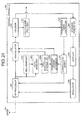
- FIG. 20 is a block diagram of a configuration of the terminal apparatus according to a sixth embodiment.
- the RRC information analyzer 801 detects from the RRC message output from the logic channel analyzer 305, switching information concerning a connected mode and an idle mode.
- the connected mode is, for example, a connected mode prescribed under LTE.
- the idle mode is, for example, an idle mode prescribed under LTE.
- the RRC information analyzer 801 outputs the detected switching information to the demodulator 303 and the carrier count switch 307.
- the demodulator 303 switches between the connected mode and the idle mode, based on the switching information output from the RRC information analyzer 801.
- the carrier count switch 307 switches the communication mode, based on the switching information output from the RRC information analyzer 801. For example, when the terminal apparatus 300 is in the connected mode, the carrier count switch 307 switches the communication mode to the multi-carrier mode. Further, when the terminal apparatus 300 is in the idle mode, the carrier count switch 307 switches the communication mode to the multi-carrier mode.
- FIG. 21 is a block diagram of a configuration of the base station apparatus according to the sixth embodiment.
- the base station apparatus 400 according to the sixth embodiment includes an RRC message generator 2101 in place of the DRX cycle setting controller 901 in the configuration depicted in FIG. 9 .
- the scheduler 401 determines whether to switch between the connected mode and the idle mode of the terminal apparatus 300.
- the scheduler 401 notifies the RRC message generator 2101 and the modulator 405 of the scheduling results.
- the RRC message generator 2101 generates switching information indicating switching to the connected mode or to the idle mode, based on the scheduling results from the scheduler 401.
- the RRC message generator 2101 outputs to the encoder 404, an RRC message that includes the generated switching information.
- the encoder 404 stores the RRC message output from the RRC message generator 2101 to data output from the binary data buffer 403.
- the encoder 404 encodes the data to which the RRC has been stored, and outputs the encoded data to the modulator 405.
- the RF processor 406 converts the frequency of the RRC completion signal output from the antenna 407, from a high frequency wave to a baseband, and outputs the frequency converted RRC completion signal to the demodulator 408.
- the demodulator 408 demodulates the RRC completion signal output from the RF processor 406 and outputs the demodulated RRC completion signal to the decoder 902.
- the decoder 902 decodes the RRC completion signal output from the demodulator 408.
- the decoder 902 outputs the decoded RRC completion signal to the RRC completion signal determiner 903.
- the RRC completion signal determiner 903 makes a determination concerning the RRC completion signal output from the decoder 902. For example, the RRC completion signal determiner 903 determines whether RRC completion signal is an RRC completion signal that is in response to switching information requesting switching to the connected mode, or an RRC completion signal that is in response to switching information requesting switching to the idle mode.
- the RRC completion signal determiner 903 notifies the carrier count switch 410 of the determination results.
- the carrier count switch 410 switches the communication mode of the base station apparatus 400, based on the determination results from the RRC completion signal determiner 903. For example, when the RRC completion signal determiner 903 reports that an RRC completion signal has been acquired in response to switching information requesting switching to the connected mode, the carrier count switch 410 switches the communication mode to the multi-carrier mode. When the RRC completion signal determiner 903 reports that an RRC completion signal has been acquired in response to switching information requesting switching to the idle mode, the carrier count switch 410 switches the communication mode to the single carrier mode.
- FIG. 22 is a flowchart of an example of operations of the terminal apparatus according to the sixth embodiment.
- the terminal apparatus 300 (see FIG. 20 ), for example, performs the following operations.
- the carrier count switch 307 determines whether the terminal apparatus 300 is in the connected mode (step S2201). If the terminal apparatus 300 is not in the connected mode (step S2201: NO), the flow proceeds to step S2203.
- step S2201 if the terminal apparatus 300 is in the connected mode (step S2201: YES), the carrier count switch 307 switches the communication mode of the terminal apparatus 300 to the multi-carrier mode (step S2202). Next, the carrier count switch 307 determines whether the terminal apparatus 300 is in the idle mode (step S2203).
- step S2203 if the terminal apparatus 300 is not in the idle mode (step S2203: NO), the flow returns to step S2201 and operations therefrom are continued. If the terminal apparatus 300 is in the idle mode (step S2203: YES), the carrier count switch 307 switches the communication mode of the terminal apparatus 300 to the single carrier mode (step S2204); and the flow returns to step S2201 and the operations therefrom are continued. By performing the operations above, the terminal apparatus 300 can switch the communication mode, based on switching information.
- FIG. 23 is a flowchart of an example of operations of the base station apparatus according to the sixth embodiment.
- the base station apparatus 400 (see FIG. 21 ), for example, performs the following operations.
- the RRC completion signal determiner 903 determines whether an RRC completion signal has been received from the terminal apparatus 300 in response to switching information that was transmitted to the terminal apparatus 300 and requested switching to the connected mode (step S2301).
- step S2301 if an RRC completion signal in response to the switching information has not been received (step S2301: NO), the flow proceeds to step S2303. If an RRC completion signal in response to the switching information has been received (step S2301: YES), the scheduler 401 switches the communication mode of the base station apparatus 400 to the single carrier mode (step S2302).
- the RRC completion signal determiner 903 determines whether an RRC completion signal has been received from the terminal apparatus 300 in response to switching information that was transmitted to the terminal apparatus 300 and requested switching to the idle mode (step S2303). If an RRC completion signal in response to the switching information has not been received (step S2303: NO), the flow returns to step S2301 and operations therefrom are continued.
- step S2303 if an RRC completion signal in response to the switching information has been received (step S2303: YES), the carrier count switch 410 switches the communication mode to the multi-carrier mode (step S2304); and the flow returns to step S2301 and operations therefrom are continued.
- the base station apparatus 400 can switch the communication mode, based on an RRC completion signal that has been transmitted by the terminal apparatus 300, based on the switching information.
- the terminal apparatus 300 acquires switching information indicating switching to the connected mode or the idle mode of the terminal apparatus 300 and based on the acquired switching information, switches the communication mode. Consequently, since existing switching information can be used as information indicating a change in the communication state, communication resources can be used efficiently without new control information being communicated to/from the base station apparatus 400.
- the terminal apparatus 300 when the terminal apparatus 300 is in the connected mode, the possibility of data being transmitted from the base station apparatus 400 is higher and therefore, during the connected mode, the terminal apparatus 300 switches to the multi-carrier mode, thereby enabling communication of high throughput to be performed. Further, when the terminal apparatus 300 is in the idle mode, the possibility of data being transmitted from the base station apparatus 400 is low and therefore, during the idle mode, the terminal apparatus 300 switches to the single carrier mode, thereby enabling power consumption to be suppressed.
- the base station apparatus 400 acquires an RRC completion signal that is from the terminal apparatus 300 and in response to switching information transmitted to the terminal apparatus 300; and based on the acquired RRC completion signal, the base station apparatus 400 switches the communication mode. Consequently, since existing an RRC completion signal can be used as information indicating a change in the communication state, communication resources can be used efficiently without new control information being communicated to/from the terminal apparatus 300.
- the base station apparatus 400 upon reception of an RRC completion signal that is from the terminal apparatus 300 and in response to switching information that was transmitted to the terminal apparatus and requested switching to the connected mode, the base station apparatus 400 switches to the multi-carrier mode. Further, upon reception of an RRC completion signal that is from the terminal apparatus 300 and in response to switching information that was transmitted to the terminal apparatus 300 and requested switching to the idle mode, the base station apparatus 400 switches to the single carrier mode.
- the communication mode of the base station apparatus 400 can be switched in conjunction with the switching of communication modes by the terminal apparatus 300.
- FIG. 24 is a block diagram of a configuration of the terminal apparatus according to a seventh embodiment.
- the terminal apparatus 300 according to the seventh embodiment includes a cell searcher 2401, a level measurer 2402, a cell reselection controller 2403, and a component carrier determiner 2404 in addition to the configuration depicted in FIG. 3 .
- the antenna 301 receives synchronization channels (SCH) transmitted from base station apparatuses, including the base station apparatus 400.
- the antenna 301 outputs the received SCHs to the RF processor 302.
- the RF processor 302 converts the frequency of each of the SCHs output from the antenna 301, from a high frequency wave to a baseband and outputs the frequency converted SCHs to the demodulator 303, the cell searcher 2401 and the level measurer 2402.
- the cell searcher 2401 based on the SCHs output from the RF processor 302, performs a cell search of detecting base station apparatuses in the vicinity of the terminal apparatus 300.
- the cell searcher 2401 notifies the level measurer 2402 of base station apparatuses detected by the cell search.
- the level measurer 2402 for each base station apparatus reported by the cell searcher 2401, measures the level of the corresponding SCH output from the RF processor 302.
- the level measurer 2402 notifies the cell reselection controller 2403 of the measured SCH level for each base station apparatus.
- the cell reselection controller 2403 performs cell reselection, based on the SCH level for each base station apparatus reported by the level measurer 2402.
- the cell reselection controller 2403 for example, performs cell reselection prescribed under LTE.
- the cell reselection controller 2403 compares the SCH level of the current base station apparatus of the terminal apparatus 300 and the SCH level of another base station apparatus.
- the cell reselection controller 2403 performs cell reselection to select the other base station apparatus.
- the cell reselection controller 2403 controls the demodulator 303 to demodulate the signal from the other base station apparatus and notifies the component carrier determiner 2404 of the reselection results.
- the component carrier determiner 2404 determines the component carrier to be used for reception by the terminal apparatus 300.
- the component carrier determiner 2404 further determines the component carrier to be used for reception by the terminal apparatus 300, according to the communication mode switched to by the carrier count switch 307.
- the component carrier determiner 2404 controls the demodulator 303 to demodulate the determined component carrier.
- the component carrier determiner 2404 determines, as the component carrier after cell reselection, a component carrier of the same frequency as that used before cell reselection. Consequently, the component carrier used after cell reselection can be determined by a simple process.
- the communication mode of the terminal apparatus 300 is the single carrier mode.
- the component carrier determiner 2404 determines a component carrier of the same frequency as that used before cell reselection. Consequently, the component carrier to be used during the single carrier mode can be determined by a simple process.
- the terminal apparatus 300 includes a cell searcher 2401, a level measurer 2402, a cell reselection controller 2403, and a component carrier determiner 2404 in addition to the configuration depicted in the second embodiment (see FIG. 3 ).
- a cell searcher 2401, a level measurer 2402, a cell reselection controller 2403, and a component carrier determiner 2404 can be added to the configuration of the terminal apparatus 300 according to any one among the third to sixth embodiments, as the seventh embodiment.
- FIG. 25 is a flowchart of an example of operations of the terminal apparatus according to the seventh embodiment.
- the terminal apparatus 300 (see FIG. 24 ), for example, performs the following operations.
- the cell reselection controller 2403 determines whether cell selection criteria for performing cell reselection have been satisfied (step S2501), and waits until the cell selection criteria are satisfied (step S2501: NO).
- step S2501 when the cell reselection criteria are satisfied (step S2501: YES), the cell reselection controller 2403 performs switching to another base station apparatus (step S2502), ending a series of the operations.
- step S2501 the cell reselection controller 2403, for example, compares the SCH level of the current base station apparatus of the terminal apparatus 300 and the SCH level of another base station apparatus.
- the cell reselection controller 2403 determines that cell reselection criteria have been satisfied. By performing the operations above, the terminal apparatus 300 can perform cell reselection when cell reselection criteria are satisfied.
- FIG. 26 is a diagram of operations of the terminal apparatus according to the seventh embodiment.
- the communication resource 2610 represents a communication resource used in communication between a base station apparatus and the terminal apparatus 300 before cell reselection.
- a communication resource 2620 represents a communication resource used in communication between a base station apparatus and the terminal apparatus 300 after cell reselection.
- the horizontal axis represents frequency for the communication resource 2610 and the communication resource 2620.
- the terminal apparatus 300 communicated with a base station apparatus by a component carrier 2611 that corresponds to frequency f1 of the communication resource 2610.
- the terminal apparatus 300 performs cell reselection, as indicated by reference numeral 2602, the terminal apparatus 300 communicates with the base station apparatus by a component carrier 2621 corresponding to the same frequency f1 as the frequency f1 used before cell reselection.
- the terminal apparatus 300 uses component carriers (component carriers 2621-2623) including the component carrier 2621 and communicates with the base station apparatus.
- component carriers component carriers 2621-2623
- the terminal apparatus 300 uses the component carrier 2621 to communicate with the base station apparatus.
- the terminal apparatus 300 depicted in FIG. 24 determines, as the component carrier for reception during the single carrier mode, a component carrier that is of the same frequency as that of the component carrier received before cell reselection. Consequently, component carrier determination after cell reselection and component carrier determination during the single carrier mode can be performed by a simple process.
- FIG. 27 is a block diagram of a first modification of the terminal apparatus according to the seventh embodiment.
- the terminal apparatus 300 according to the seventh embodiment includes a handover controller 2701 in place of the cell reselection controller 2403 depicted in FIG. 24 .
- the level measurer 2402 notifies the handover controller 2701 of the SCH level of each base station apparatus.
- the handover controller 2701 performs handover based on the SCH levels reported by the level measurer 240.
- the handover controller 2701 for example, performs handover prescribed under LTE.
- the handover controller 2701 compares the SCH level of the base station apparatus with which the terminal apparatus 300 is communicating and the SCH level of another base station apparatus.
- the handover controller 2701 When the SCH level of the base station apparatus (e.g., connected mode) with which the terminal apparatus 300 is communicating becomes lower than the SCH level of another base station apparatus, the handover controller 2701 performs handover to the other base station apparatus. In this case, the handover controller 2701 controls the demodulator 303 to demodulate a signal of the other base station apparatus and notifies the component carrier determiner 2404 of the handover determination results.
- the handover controller 2701 controls the demodulator 303 to demodulate a signal of the other base station apparatus and notifies the component carrier determiner 2404 of the handover determination results.
- the component carrier determiner 2404 determines the component carrier to be used for reception by the terminal apparatus 300.
- the component carrier determiner 2404 further determines the component carrier to be used for reception by the terminal apparatus, according to the communication mode switched to by the carrier count switch 307.
- the component carrier determiner 2404 controls the demodulator 303 to demodulate the determined component carrier.
- the component carrier determiner 2404 determines as a component carrier to be used after handover, a component carrier of the same frequency as the frequency used before handover. Consequently, a component carrier to be used after handover can be determined by a simple process.
- the component carrier determiner 2404 determines, as the component carrier to be used, a component carrier of the same frequency used before handover. Consequently, a component carrier to be used during the single carrier mode can be determined by a simple process.
- the terminal apparatus 300 depicted in FIG. 27 determines, as the component carrier for reception during the single carrier mode after handover, a component carrier of the same frequency as that of the component carrier received before handover. Consequently, a component carrier after handover and a component carrier during the single carrier mode can be determined by a simple process.
- FIG. 28 is a block diagram of a second modification of the terminal apparatus according to the seventh embodiment.
- the terminal apparatus 300 according to the seventh embodiment includes a reconnection controller 2801 in place of the cell reselection controller 2403 depicted in FIG. 24 .
- the level measurer 2402 notifies the reconnection controller 2801 of the measured level for each base station apparatus. Based on the SCH level that is of the base station apparatus with communication is being performed and output from the level measurer 2402, the reconnection controller 2801 performs reconnection to the cell with which communication is being performed.
- the reconnection controller 2801 for example, performs reconnection prescribed under LTE. For example, the reconnection controller 2801 compares the SCH level of the base station apparatus with which the terminal apparatus 300 is communicating and a given threshold.
- the reconnection controller 2801 reconnects to the base station apparatus.
- the reconnection controller 2801 performs a reconnection process with respect to the demodulator 303 and notifies the component carrier determiner 2404 of the reconnection determination results.
- the component carrier determiner 2404 determines a component carrier to be used for reception by the terminal apparatus 300.
- the component carrier determiner 2404 determines, as a component carrier to be used after reconnection, a component carrier that is of the same frequency as the frequency used before reconnection. Consequently, a component carrier to be used after reconnection can be determined by a simple process.
- the component carrier determiner 2404 determines, as a component carrier to be used, a component carrier that is of the same frequency as the frequency used before the reconnection. Consequently, a component carrier to be used during the single carrier mode can be determined by a simple process.
- the terminal apparatus 300 depicted in FIG. 28 determines, as a component carrier to be used for reception during the single carrier mode after reconnection, a component carrier that is of the same frequency as that received before reconnection. Consequently, the process of determining a component carrier to be used after reconnection and a component carrier to be used during the single carrier mode can be simplified.
- communication resources can be used efficiently.
- the communication resources are component carriers prescribed under LTE-Advanced
- the communication resources are not limited to the component carriers and communication resources of divided physical resources are applicable overall.
- each of the communication apparatuses is described to have a multi-carrier mode and a single carrier mode as communication modes
- the communication modes of the communication apparatuses is not limited to the multi-carrier mode and the single carrier mode, and may be any communication mode provided the number of communication carriers to be used differ.
- the communication apparatuses may have in place of the multi-carrier mode, a first communication mode that uses a given number of communication carriers; and in place of the single carrier mode, a second communication mode that uses fewer communication carriers than the given number above.
- the disclosed communication apparatus, communication system, and communication method can be applied to an LTE-advanced communication scheme.
- the disclosed communication apparatus, communication system, and communication method are not limited to an LTE-advanced scheme and are applicable to communication schemes overall that can divide data among multiple physical resources and transmit the data.
Landscapes
- Engineering & Computer Science (AREA)
- Computer Networks & Wireless Communication (AREA)
- Signal Processing (AREA)
- Mobile Radio Communication Systems (AREA)
Abstract
Description
- The present invention is related to a communication apparatus, a communication system, and a communication method that perform communication.
- Under the 3rd Generation Partnership Project (3GPP), a collaboration of organizations for setting industrial standards, the establishment of Long Term Evolution (LTE)-Advanced specifications is underway. Under LTE-Advanced, an LTE system carrier (e.g., of a maximum of 20MHz) is defined as a component carrier and the aggregation of component carriers to obtain high throughput is being investigated.
- To provide a wireless data communication method and apparatus that can guarantee communication at an optimal communication speed under any line state, a wireless data communication method of a wireless data communication apparatus that wirelessly communicates data using multiple lines by a multi-ring method, has a stabilizing unit that monitors the line state, and based on the obtained monitoring information, switches data paths and performs line selection, has been disclosed (see, for example, Patent Document 1).
- A packet transferring method has been disclosed in which a wired line connecting a base station apparatus and an exchange station includes a common channel that can be commonly used by multiple terminals and exclusive channels that can be used respectively by only one terminal. When the volume of data transferred from a terminal is a given value or greater, the terminal is allocated an exclusive channel and when data is transferred using the exclusive channel, the data that is to be transferred from the terminal is queued consequent to the excessive volume of transfer data. When the volume of queued data becomes equal to or exceeds a predetermined value at which the data volume causes delay to occur, the terminal is newly allocated an exclusive channel. The exclusive channel and the additional exclusive channel are used to transfer packets until the volume of queued data becomes less than or equal to a predetermined value at which the volume of delayed data recovers (see, for example, Patent Document 2).
-
- [Patent Document 1] Japanese Laid-Open Patent Publication No.
2000-174770 - [Patent Document 2] Japanese Laid-Open Patent Publication No.
2001-024706 - However, with the conventional technologies above, a problem arises in that physical resources cannot be efficiently used. For example, when there is no data to be transferred, or when there is little data to be transferred, power is wasted using multiple component carriers for transmission and reception.
- In particular, at the communication apparatus on the receiving side, when there is no data to be transferred, or when there is little data to be transferred, wasteful power consumption is great since multiple component carriers are received to confirm whether data has been stored. Further, not limited to the component carriers prescribed by LTE-Advanced, on a whole, communication methods that separate data among communication carriers for transmission have a similar problem.
- An object of one aspect of the present invention is to efficiently use physical resources.
- According to a first aspect, a communication apparatus includes a receiver that can receive data that has been divided among multiple communication carriers and transmitted, and that has multiple communication modes that each use a different number of communication carriers reception. The communication apparatus further includes an acquirer that acquires information indicating a change in the communication state of the receiver and a switch that switches the communication mode, based on the information acquired by the acquirer.
- According to the present invention, efficient use of physical resources can be effected.
-
-
FIG. 1 is a block diagram of configuration of a communication system according to a first embodiment; -
FIG. 2 is a diagram of communication carriers used in the communication system; -
FIG. 3 is a block diagram of a configuration of a terminal apparatus according to a second embodiment; -
FIG. 4 is a block diagram of a configuration of a base station apparatus according to the second embodiment; -
FIG. 5 is a flowchart of an example of operations of a terminal apparatus according to the second embodiment; -
FIG. 6 is a flowchart of an example of operations of the base station apparatus according to the second embodiment; -
FIG. 7 is a sequence diagram of an example of operations of the communication system according to the second embodiment; -
FIG. 8 is a block diagram of configuration of the terminal apparatus according to a third embodiment; -
FIG. 9 is a block diagram of a configuration of the base station apparatus according to the third embodiment; -
FIG, 10 is a flowchart of an example of operations of the terminal apparatus according to the third embodiment; -
FIG. 11 is a flowchart of an example of operations of the base station apparatus according to the third embodiment; -
FIG. 12 is a block diagram of a configuration of the terminal apparatus according to a fourth embodiment; -
FIG. 13 is a block diagram of a configuration of the base station apparatus according to the fourth embodiment; -
FIG. 14 is a flowchart of an example of operations of the terminal apparatus according to the fourth embodiment; -
FIG. 15 is a flowchart of an example of operations of the base station apparatus according to the fourth embodiment; -
FIG. 16 is a sequence diagram of an example of operations of the communication system according to the fourth embodiment; -
FIG. 17 is a block diagram of a configuration of the terminal apparatus according to a fifth embodiment; -
FIG. 18 is a flowchart of an example of operations of the terminal apparatus according to the fifth embodiment; -
FIG. 19 is a flowchart of an example of operations of the base station apparatus according to the fifth embodiment; -
FIG. 20 is a block diagram of a configuration of the terminal apparatus according to a sixth embodiment; -
FIG. 21 is a block diagram of a configuration of the base station apparatus according to the sixth embodiment; -
FIG. 22 is a flowchart of an example of operations of the terminal apparatus according to the sixth embodiment; -
FIG. 23 is a flowchart of an example of operations of the base station apparatus according to the sixth embodiment; -
FIG. 24 is a block diagram of a configuration of the terminal apparatus according to a seventh embodiment; -
FIG. 25 is a flowchart of an example of operations of the terminal apparatus according to the seventh embodiment; -
FIG. 26 is a diagram of operations of the terminal apparatus according to the seventh embodiment; -
FIG. 27 is a block diagram of a first modification of the terminal apparatus according to the seventh embodiment; and -
FIG. 28 is a block diagram of a second modification of the terminal apparatus according to the seventh embodiment. - With reference to the accompanying drawings, preferred embodiments of the communication apparatus, the communication system, and the communication method will be described.
-
FIG. 1 is a block diagram of configuration of a communication system according to a first embodiment. As depicted inFIG. 1 , acommunication system 100 according to a first embodiment includes afirst communication apparatus 110 and asecond communication apparatus 120. In this example, configurations of thefirst communication apparatus 110 and thesecond communication apparatus 120 will be described for transmitting data from thefirst communication apparatus 110 to thesecond communication apparatus 120. Nonetheless, thefirst communication apparatus 110 and thesecond communication apparatus 120 may be configured to transmit data from thesecond communication apparatus 120 to thefirst communication apparatus 110. - The
first communication apparatus 110 includes atransmitter 111, anacquirer 112, and aswitch 113. Thetransmitter 111 can divide data among multiple communication carriers and transmit the data, and has multiple communication modes, each using a different number of communication carriers for transmission. For example, thetransmitter 111 has a multi-carrier mode and a single carrier mode, as communication modes. - The multi-carrier mode is a communication mode in which multiple transmitting communication carriers are used. When in the multi-carrier mode, the
transmitter 111 divides data among multiple communication carriers and transmits the data. The single carrier mode is a communication mode in which a single transmitting communication carrier is used. When in the single carrier mode, thetransmitter 111 transmits data by a single carrier. - The
acquirer 112 acquires information indicating a change in the communication state of thetransmitter 111.
A change in the communication state of thetransmitter 111, for example, is a change in the volume of data transmitted by thetransmitter 111. A change in the communication state of thetransmitter 111 may be a change in whether thetransmitter 111 has data to transmit. Theacquirer 112 outputs the acquired information to theswitch 113. - The
switch 113 switches the communication mode of thetransmitter 111, based on the information acquired by theacquirer 112. For example, if the information output from theacquirer 112 indicates that the volume of data transmitted by thetransmitter 111 exceeds a given volume, theswitch 113 switches the communication mode of thetransmitter 111 to the multi-carrier mode. Further, if the information output from theacquirer 112 indicates that the volume of data transmitted by thetransmitter 111 is less than or equal to the given volume, theswitch 113 switches the communication mode of thetransmitter 111 to the single carrier mode. - Configuration may be such that if the information output from the
acquirer 112 indicates that there is data to be transmitted by thetransmitter 111, theswitch 113 switches the communication mode of thetransmitter 111 to the multi-carrier mode. Further, configuration may be such that if the information output from theacquirer 112 indicates that there is no data to be transmitted by thetransmitter 111, theswitch 113 switches the communication mode of thetransmitter 111 to the single carrier mode. - The
second communication apparatus 120 includes areceiver 121, anacquirer 122, and aswitch 123. Thereceiver 121 can receive data that has been divided among multiple communication carriers and transmitted, and has multiple communication modes, each using a different number of communication carriers for reception. For example, thereceiver 121 has a multi-carrier mode and a single carrier mode as communication modes. - The multi-carrier mode is a communication mode in which multiple receiving communication carriers are used. When in the multi-carrier mode, the
receiver 121 receives data that has been divided among multiple communication carriers and transmitted. The single carrier mode is a communication mode in which a single receiving communication carrier is used. When in the signal carrier mode, thereceiver 121 receives data by a single carrier. - The
acquirer 122 acquires information indicating a change in the communication state of thereceiver 121. A change in the communication state of thereceiver 121, for example, is a change in the volume of data received by thereceiver 121. A change in the communication state of thereceiver 121 may be a change in whether there is data to be received by thereceiver 121. Theacquirer 122 outputs the acquired information to theswitch 123. - The
switch 123 switches the communication mode of thereceiver 121, based on the information acquired by theacquirer 122. For example, if the information output from theacquirer 122 indicates that the volume of data received byreceiver 121 exceeds a given volume, theswitch 123 switches the communication mode of thereceiver 121 to the multi-carrier mode. If the information output from theacquirer 122 indicates that the volume of data received by thereceiver 121 is less than or equal to the given volume, theswitch 123 switches the communication mode of thereceiver 121 to the single carrier mode. - Configuration may be such that if the information output from the
acquirer 122 indicates that there is data to be received by thereceiver 121, theswitch 123 switches the communication mode of thereceiver 121 to the multi-carrier mode. In this case, if the information output from theacquirer 122 indicates that there is no data to be received by thereceiver 121, theswitch 123 switches the communication mode of thereceiver 121 to the single carrier mode. - The
transmitter 111 of thefirst communication apparatus 110 is implemented by, for example, a wireless communication interface such as an antenna and communication control circuit. Theacquirer 112 of thefirst communication apparatus 110 is implemented by, for example, an information processor such as a digital signal processor (DSP). Theacquirer 112 stores the acquired information to a memory of thefirst communication apparatus 110. Theswitch 113 of thefirst communication apparatus 110 is implemented by, for example, an information processor such as a DSP. Theswitch 113 reads out the information stored to the memory by theacquirer 112 and based on the read information, switches the communication mode. - The
receiver 121 of thesecond communication apparatus 120 is implemented by, for example, a wireless communication interface such as an antenna and communication control circuit. Theacquirer 122 of thesecond communication apparatus 120 is implemented by, for example an information processor such as a DSP. Theacquirer 122 stores the acquired information to a memory of thesecond communication apparatus 120. Theswitch 123 of thesecond communication apparatus 120 is implemented by, for example, an information processor such as a DSP. Theswitch 123 reads out the information stored to the memory by theacquirer 122 and based on the read information, switches the communication mode. -
FIG. 2 is a diagram of communication carriers used in the communication system. InFIG. 2 , the horizontal axis represents frequency.Communication carriers 201 to 203 each represent system carriers divided by frequency. When in the multi-carrier mode, thetransmitter 111 of thefirst communication apparatus 110, for example, divides data among thecommunication carriers 201 to 203 and transmits the data. Further, when in the single carrier mode, thetransmitter 111 of thefirst communication apparatus 110 transmits data by thecommunication carrier 201. - When in the multi-carrier mode, the
receiver 121 of thesecond communication apparatus 120, for example, receives data that has been divided among thecommunication carriers 201 to 203 and transmitted. Further, when thetransmitter 111 of thefirst communication apparatus 110 is in the single carrier mode, for example, thereceiver 121 receives data transmitted by thecommunication carrier 201. - In this manner, according to communication state, the
communication system 100 of the first embodiment switches between communication modes of differing component carrier counts. Consequently, when the volume of data to be transmitted is great, a communication mode of a large number of component carriers (e.g., the multi-carrier mode) is switched to, whereby communication of high throughput can be performed. - Further, when there is little or no data to be transmitted, a communication mode of a small number of component carriers (e.g., the single carrier mode) is switched to, whereby power consumption of the
first communication apparatus 110 and thesecond communication apparatus 120 can be suppressed. In this manner, according to thecommunication system 100, communication resources can be used efficiently. -
FIG. 3 is a block diagram of a configuration of a terminal apparatus according to a second embodiment. As depicted inFIG. 3 , aterminal apparatus 300 according to the second embodiment includes anantenna 301, anRF processor 302, ademodulator 303, a decoder 304, alogic channel analyzer 305, atransmission timing controller 306, acarrier count switch 307, an ACK/NACK generator 308, anencoder 309, and amodulator 310. - The
terminal apparatus 300 corresponds to, for example, thesecond communication apparatus 120 depicted inFIG. 1 . Further, theterminal apparatus 300, for example, is a terminal apparatus that is compliant with LTE-Advanced.
Theterminal apparatus 300 can receive data that has been divided among multiple component carriers (communication carriers) and transmitted, and has multiple communication modes, each using a different number of communication carriers. For example, as communication modes, theterminal apparatus 300 has the multi-carrier mode in which multiple receiving communication carriers are used and the single carrier mode in which a single receiving communication carrier is used. - The
antenna 301, theRF processor 302, thedemodulator 303, and the decoder 304, for example, correspond to thereceiver 121 depicted inFIG. 1 . Thelogic channel analyzer 305, for example, corresponds to theacquirer 122 depicted inFIG. 1 . Thecarrier count switch 307, for example, corresponds to theswitch 123 depicted inFIG. 1 . - The
antenna 301 is an antenna for performing wireless communication with a base station apparatus (e.g., abase station apparatus 400 depicted inFIG. 4 ). For example, theantenna 301 receives a signal transmitted by the base station apparatus and outputs the signal to theRF processor 302. Theantenna 301 further transmits to the base station apparatus, a delivery confirmation signal (ACK or NACK) output from theRF processor 302. - The
RF processor 302 converts the frequency of the signal output from theantenna 301, from a high frequency wave (radio frequency (RF)) to a baseband, and outputs the frequency converted signal to thedemodulator 303. TheRF processor 302 further converts the frequency of the delivery confirmation signal output from themodulator 310, from a baseband to a high frequency wave, and outputs the frequency converted delivery confirmation signal to theantenna 301. - The
demodulator 303 demodulates the signal output from theRF processor 302 and outputs the demodulated signal to the decoder 304. The decoder 304 decodes the signal output from thedemodulator 303 and outputs the data resulting from the decoding, to thelogic channel analyzer 305. For example, the decoder 304 performs signal error correction and decoding (forward error correction (FEC)) and notifies the ACK/NACK generator 308 of the results. - The
logic channel analyzer 305 performs logic channel analysis on the data output from the decoder 304. For example, thelogic channel analyzer 305 acquires binary data included in the data and outputs the acquired binary data downstream. Binary data is, for example, user data transmitted by the base station apparatus. Thelogic channel analyzer 305 further acquires, as information indicating changes in communication state, a timing command included in the data. - For example, from the area storing the logic channel ID of the data, the
logic channel analyzer 305 detects an ID representing a timing command and acquires the timing command from the area corresponding to the detected ID. A timing command is a command indicating the timing at which theterminal apparatus 300 is to transmit the data to the base station apparatus. - For example, a timing command is indicated by a difference from the previous transmission timing of the
terminal apparatus 300. A valid period is set for the timing command. The length of the valid period, for example, is set by the base station apparatus when theterminal apparatus 300 first connects to the base station apparatus. Thelogic channel analyzer 305 outputs the acquired timing command to thetransmission timing controller 306. - The
transmission timing controller 306, based on the timing command output from thelogic channel analyzer 305, controls the transmission timing of data (user data) transmitted by theterminal apparatus 300. However, inFIG. 3 , configuration for transmitting data from theterminal apparatus 300 is omitted. Thetransmission timing controller 306 notifies thecarrier count switch 307 of the acquisition of the timing command. - The
carrier count switch 307 has a function of a synchronous timer that times the valid period of the timing command. Upon being notified, by thetransmission timing controller 306, of the acquisition of the timing command, thecarrier count switch 307 starts timing the valid period by the synchronous timer. Thecarrier count switch 307, based on the valid period of the timing command timed by the synchronous timer, switches the communication mode of theterminal apparatus 300. - For example, the
carrier count switch 307 sets the communication mode to the multi-carrier mode during the valid period of the timing command. Outside the valid period of the timing command, thecarrier count switch 307 sets the communication mode to the single carrier mode. - For example, the
carrier count switch 307 sets the communication mode to the multi-carrier mode by setting theRF processor 302 and thedemodulator 303 to perform reception operations by multiple component carriers. Thecarrier count switch 307 further sets the communication mode to the single carrier mode by setting theRF processor 302 and thedemodulator 303 to perform reception operations by a single component carrier. - The ACK/
NACK generator 308 generates a delivery confirmation signal, based on the error correction and decoding results from the decoder 304. For example, the ACK/NACK generator 308 generates an ACK signal when the decoder 304 reports no errors or successful correction of errors and generates a NACK signal when the decoder 304 reports failure to correct errors. The ACK/NACK generator 308 outputs the generated delivery confirmation signal to theencoder 309. - The
encoder 309 encodes the delivery confirmation signal output from the ACK/NACK generator 308. Theencoder 309 outputs the encoded delivery confirmation signal to themodulator 310. Themodulator 310 modulates the delivery confirmation signal output from theencoder 309 and outputs the modulated delivery confirmation signal to theRF processor 302. -
FIG. 4 is a block diagram of a configuration of the base station apparatus according to the second embodiment. As depicted inFIG. 4 , thebase station apparatus 400 according to the second embodiment includes a scheduler 401, a transmission timing controller 402, abinary data buffer 403, anencoder 404, amodulator 405, anRF processor 406, anantenna 407, ademodulator 408, an ACK/NACK determiner 409, and acarrier count switch 410. - The
base station apparatus 400, for example, corresponds to thefirst communication apparatus 110 depicted inFIG. 1 . Thebase station apparatus 400 is, for example, a base station apparatus that is compliant with LTE-Advanced. Thebase station apparatus 400 can divide data among multiple component carriers (communication carriers) and transmit the data, and has multiple communication modes, each using a different number of communication carriers for transmission. For example, as communication modes, thebase station apparatus 400 has the multi-carrier mode in which multiple transmitting communication carriers are used and the single carrier mode in which a single transmitting communication carrier is used. - The scheduler 401, the transmission timing controller 402, the
encoder 404, themodulator 405, theRF processor 406, and theantenna 407 correspond to, for example, thetransmitter 111 depicted inFIG. 1 . Thedemodulator 408 and the ACK/NACK determiner 409 correspond to, for example, theacquirer 112 depicted inFIG. 1 . Thecarrier count switch 410 corresponds to, for example, theswitch 113 depicted inFIG. 1 . - The scheduler 401 schedules communication between the
terminal apparatus 300 and thebase station apparatus 400. For example, the scheduler 401 determines the bit count of the data transmitted by thebase station apparatus 400 to each terminal apparatus. The scheduler 401, based on the communication mode of thebase station apparatus 400 set by thecarrier count switch 410, further determines the component carrier to be used for each communication. - For example, when the multi-carrier mode is set by the
carrier count switch 410, the scheduler 401 performs scheduling such that multiple component carriers are used to transmit data. Further, when the single carrier mode is set by thecarrier count switch 410, the scheduler 401 performs scheduling such that a single component carrier is used to transmit data. - The scheduler 401 notifies the transmission timing controller 402 and the
modulator 405 of the scheduling results. The scheduler 401, based on the scheduling results, further outputs to thebinary data buffer 403, an instruction to output data. Thebinary data buffer 403 stores therein data (binary data) for transmissions to theterminal apparatus 300. Upon output of an output instruction from the scheduler 401, thebinary data buffer 403 outputs the stored data to theencoder 404. - The transmission timing controller 402, based on the scheduling results from the scheduler 401, generates a timing command that indicates the timing at which the
terminal apparatus 300 is to transmit a delivery confirmation signal in response to the data transmitted by thebase station apparatus 400. The transmission timing controller 402 outputs the generated timing command to theencoder 404. - The
encoder 404 stores the timing command output from the transmission timing controller 402 to the data output from thebinary data buffer 403. Theencoder 404 encodes the data to which the timing command has been stored and outputs the encoded data to themodulator 405. Themodulator 405 modulates the data output from theencoder 404 and outputs to theRF processor 406, the signal obtained by the encoding. - The
modulator 405 modulates the data by communication resources (physical resources) corresponding to the component carriers indicated by the scheduling results from the scheduler 401. For example, upon notification that data is to be divided among multiple component carriers and transmitted, themodulator 405 performs data modulation by communication resources corresponding the component carriers. Upon receiving notification that data is to be transmitted by a single component carrier, themodulator 405, performs data modulation by the communication resource corresponding to the component carrier. - The
RF processor 406 converts the frequency of the signal output from themodulator 405, from a baseband to a high frequency wave, and outputs the frequency converted signal to theantenna 407. TheRF processor 406 further converts the frequency of a delivery confirmation signal output from theantenna 407, from a high frequency wave to a baseband, and outputs the frequency converted delivery confirmation signal to thedemodulator 408. - The
antenna 407 is an antenna for performing wireless communication with theterminal apparatus 300. For example, theantenna 407 receives a delivery confirmation signal transmitted by theterminal apparatus 300 and outputs the received delivery confirmation signal to theRF processor 406. Theantenna 407 further transmits to theterminal apparatus 300, the signal output from theRF processor 406. - The
demodulator 408 demodulates the delivery confirmation signal output from theRF processor 406 and outputs the demodulated delivery confirmation signal to the ACK/NACK determiner 409. The ACK/NACK determiner 409 judges the delivery confirmation signal output from thedemodulator 408. For example, the ACK/NACK determiner 409 determines whether the delivery confirmation signal is in response to any one of the signals, and determines whether the delivery confirmation signal is any one of an ACK signal and a NACK signal. The ACK/NACK determiner 409 notifies thecarrier count switch 410 of the results of determination. - The
carrier count switch 410 switches the communication mode of thebase station apparatus 400, based on the determination results from the ACK/NACK determiner 409. For example, when the determination results from the ACK/NACK determiner 409 indicate that an ACK signal has been received in response to the timing command, thecarrier count switch 410 switches the communication mode to the multi-carrier mode. - The
carrier count switch 410 has a synchronous timer function that times the valid period of the timing command transmitted by thebase station apparatus 400 to theterminal apparatus 300. Based on the synchronous timer, thecarrier count switch 410 switches the communication mode to the single carrier mode, when the time is outside the valid period of the timing command. - For example, the
carrier count switch 410 sets the scheduler 401 to perform scheduling for multiple component carriers, and thereby sets the communication mode of thebase station apparatus 400 to the multi-carrier mode. Thecarrier count switch 410 sets the scheduler 401 to perform scheduling for a single component carrier, and thereby sets the communication mode of thebase station apparatus 400 to the single carrier mode. -
FIG. 5 is a flowchart of an example of operations of the terminal apparatus according to the second embodiment. The terminal apparatus 300 (seeFIG. 3 ), for example, performs the following operations. As depicted inFIG. 5 , thecarrier count switch 307 determines whether a timing command from thebase station apparatus 400 has been received (step S501). If a timing command has not been received (step S501: NO), the flow proceeds to step S504. - At step S501, if a timing command has been received (step S501: YES), the
carrier count switch 307 starts operation of the synchronous timer that times the valid period of the timing command (step S502). Thecarrier count switch 307 switches the communication mode of theterminal apparatus 300 to the multi-carrier mode (step S503). Thecarrier count switch 307 determines whether the synchronous timer started at step S502 has expired (step S504). - At step S504, if the synchronous timer has not expired (step S504: NO), the flow returns to step S501 and processes therefrom are continued. If the synchronous timer has expired (step S504: YES), the
carrier count switch 307 switches the communication mode of theterminal apparatus 300 to the single carrier mode (step S505), the flow returns to step S501 and operations therefrom are continued. By performing the above operations, theterminal apparatus 300 can switch the communication mode, based on the valid period of an acquired timing command. -
FIG. 6 is a flowchart of an example of operations of the base station apparatus according to the second embodiment. The base station apparatus 400 (seeFIG. 4 ), for example, performs the following operations. As depicted inFIG. 6 , the ACK/NACK determiner 409 determines whether an ACK signal has been received in response to a timing command transmitted to the terminal apparatus 300 (step S601). If an ACK signal has not been received (step S601: NO), the flow proceeds to step S604. - At step S601, if an ACK signal has been received in response to the timing command (step S601: YES), the
carrier count switch 410 starts operation of the synchronous timer that times the valid period of the timing command (step S602). Thecarrier count switch 410 switches the communication mode to the multi-carrier mode (step S603). Thecarrier count switch 410 determines whether the period of the synchronous timer started at step S602 has expired (step S604). - At step S604, if the timer of the synchronous timer has not expired (step S604: NO), the flow returns to step S601 and processes therefrom are continued. If the period of the synchronous timer has expired (step S604: YES), the
carrier count switch 410 switches the communication mode to the single carrier mode (step S605); the flow returns to step S601 and the operations therefrom are continued. By performing the above operations, thebase station apparatus 400 can switch the communication mode, based on an acquired delivery confirmation signal that is from theterminal apparatus 300 and in response to the timing command transmitted to theterminal apparatus 300. -
FIG. 7 is a sequence diagram of an example of operations of the communication system according to the second embodiment. When there is transmission data to be transmitted at the base station apparatus 400 (step S701), thebase station apparatus 400 transmits a timing command to the terminal apparatus 300 (step S702). Period t1 represents the valid period of the timing command transmitted at step S702. Thebase station apparatus 400 transmits to theterminal apparatus 300, a portion of the transmission data at step S701 (step S703). - The
terminal apparatus 300 transmits an ACK signal to thebase station apparatus 400, in response to the data transmitted at step S703 (step S704). Thebase station apparatus 400 transmits a timing command to the terminal apparatus 300 (step S705). Period t2 represents the valid period of the timing command transmitted at step S705. Thebase station apparatus 400 transmits to theterminal apparatus 300, a portion of the transmission data at step S701 (step S706). - The
terminal apparatus 300 transmits an ACK signal to thebase station apparatus 400, in response to the data transmitted at step S706 (step S707). Here, it is assumed that all of the transmission data at step S701 has been received by theterminal apparatus 300 through the steps above. Subsequently, thebase station apparatus 400 terminates the transmission process (step S708), ending the series of operations. - During the steps above, the communication modes of the
terminal apparatus 300 and thebase station apparatus 400 are set as the multi-carrier mode during period T when at least one of the periods t1 and t2 is being timed. Further, during periods outside the period T, theterminal apparatus 300 and thebase station apparatus 400 are in the single carrier mode. - In
FIG. 7 , an example where the data transmitted at step S703 and step S706 is properly received by theterminal apparatus 300 and an ACK signal is transmitted by theterminal apparatus 300 to thebase station apparatus 400 has been described. In contrast, when the data is not properly received by theterminal apparatus 300 and a NACK signal is transmitted by theterminal apparatus 300 to thebase station apparatus 400, thebase station apparatus 400 again transmits the data to theterminal apparatus 300. - Configuration may be such that at the
base station apparatus 400, the timing of period t1 begins when an ACK signal (not depicted) that is from theterminal apparatus 300 and in response to the transmitted timing command is received. In this case as well, for example, when data is transmitted at step S703 and step S706, the communication mode of thebase station apparatus 400 may be switched to the multi-carrier mode. - As depicted in
FIG. 7 , thebase station apparatus 400 periodically transmits a timing command to theterminal apparatus 300 during the data transmission process, whereby during the data transmission process, theterminal apparatus 300 and thebase station apparatus 400 are switched to the multi-carrier mode, enabling communication of high throughput to be performed. - Upon completing the data transmission process, the
base station apparatus 400 suspends the transmission of the timing command. Consequently, after the data transmission process, the valid period of the timing command expires and theterminal apparatus 300 and thebase station apparatus 400 are switched to the single carrier mode, thereby enabling power consumption of theterminal apparatus 300 and thebase station apparatus 400 to be suppressed. - In this manner, the
terminal apparatus 300 according to the second embodiment acquires, as information indicating a change in the communication state, a timing command that indicates the timing at which theterminal apparatus 300 is to transmit a signal. The timing command, for example, is a timing command that indicates the timing at which theterminal apparatus 300 is to transmit a delivery confirmation signal in response to data received by theterminal apparatus 300. - The
terminal apparatus 300 switches the communication mode, based on the valid period of the acquired timing command. Since an existing timing command can be used as information indicating a change in the communication state, communication resources can be used efficiently without new control information being communicated to/from thebase station apparatus 400. - For example, during the valid period of the timing command, the possibility of data being transmitted from the
base station apparatus 400 is high and therefore, theterminal apparatus 300 switches to the multi-carrier mode during the valid period of the timing command, enabling communication of high throughput to be performed. Outside the valid period of the timing command, the possibility of data being transmitted from thebase station apparatus 400 is low and therefore, theterminal apparatus 300 switches to the single carrier mode during periods outside the valid period of the timing command, thereby enabling power consumption to be suppressed. - Furthermore, since new control information need not be communicated, efficient use of communication resources can be achieved without large design modifications. In addition, pressure on the communication resources consequent to the communication of new control information can be prevented. Delays in the switching of the communication mode consequent to the communication of new control information can also be prevented.
- The
base station apparatus 400 according to the second embodiment acquires, as information indicating a change in the communication state, a delivery confirmation signal that is from theterminal apparatus 300 and in response to a timing command transmitted to theterminal apparatus 300; and based on the delivery confirmation signal, switches the communication mode. Since an existing timing command can be used as information indicating a change in the communication state, communication resources can be used efficiently without new control information being communicated to/from theterminal apparatus 300. - For example, when a delivery confirmation signal that is in response to a timing command and from the
terminal apparatus 300 is acquired, thebase station apparatus 400 switches to the multi-carrier mode during the valid period of the timing command and to the single carrier mode outside the valid period of the timing command. Consequently, since the communication mode is switched after confirmation of the timing command being properly received by theterminal apparatus 300, the communication mode of thebase station apparatus 400 can be switched in conjunction with the switching of communication modes by theterminal apparatus 300. - For communication in which a delivery confirmation signal is not communicated, the
base station apparatus 400 does not transmit to theterminal apparatus 300, a timing command for the transmission of a delivery confirmation signal and therefore, the communication modes of theterminal apparatus 300 and thebase station apparatus 400 are the single carrier mode. For communication in which a delivery confirmation signal Is not communicated, the volume of data is often small and thus, in this case, sufficient throughput can be achieve by the single carrier mode and power consumption can be suppressed. - For example, for paging control channels (PCCH) and broadcast control channels (BCCH) under LTE, although a delivery confirmation signal is not communicated, the data rate is low. In the second embodiment, for PCCHs and BCCHs, since the communication mode remains as the single carrier mode, sufficient throughput can be achieved and power consumption can be suppressed.
- The timing command may be a timing command that indicates the timing at which the
terminal apparatus 300 is to transmit data (user data) to thebase station apparatus 400. For example, when there is data to be transmitted to thebase station apparatus 400, theterminal apparatus 300 accesses thebase station apparatus 400 by random access and acquires from thebase station apparatus 400, a timing command for the transmission of data. - In this case as well, the
base station apparatus 400 switches the communication mode, based on the acquired valid period of the timing command, thereby enabling efficient use of communication resources. The number of component carriers used in the multi-carrier mode may differ for downlinks from thebase station apparatus 400 to theterminal apparatus 300 and uplinks from theterminal apparatus 300 to thebase station apparatus 400. -
FIG. 8 is a block diagram of configuration of the terminal apparatus according to a third embodiment. InFIG. 8 , components identical to those depicted inFIG. 3 are given the same reference numerals used inFIG. 3 and description thereof is omitted. As depicted inFIG. 8 , theterminal apparatus 300 according to the third embodiment includes anRRC information analyzer 801 and an RRCcompletion signal generator 802 in place of thetransmission timing controller 306 and the ACK/NACK generator 308 in the configuration depicted inFIG. 3 . - The decoder 304 outputs error correction and decoding results to the RRC
completion signal generator 802. Thelogic channel analyzer 305 acquires a radio resource control (RRC) message included in the data output from the decoder 304. Thelogic channel analyzer 305 outputs the acquired RRC message to theRRC information analyzer 801. - The
RRC information analyzer 801 detects DRX (discontinuous reception) information, from the RRC message output from thelogic channel analyzer 305. The DRX information includes a DRX setting signal requesting theterminal apparatus 300 to set a DRX cycle and a DRX cancellation signal requesting theterminal apparatus 300 to cancel the set DRX cycle. TheRRC information analyzer 801 outputs the detected DRX information to thedemodulator 303 and thecarrier count switch 307. - The
demodulator 303 performs discontinuous reception, based on the DRX information output from theRRC information analyzer 801. For example, when a DRX setting signal is output from theRRC information analyzer 801, thedemodulator 303 sets the DRX cycle and performs discontinuous reception, based on DRX setting signal. When a DRX cancellation signal is output from theRRC information analyzer 801, thedemodulator 303 cancels the DRX cycle and terminates discontinuous reception. - The
carrier count switch 307 switches the communication mode, based on the DRX information output from theRRC information analyzer 801. For example, when a DRX setting signal is output from theRRC information analyzer 801, thecarrier count switch 307 switches the communication mode of theterminal apparatus 300 to the multi-carrier mode. When a DRX cancellation signal is output from theRRC information analyzer 801, thedemodulator 303 switches the communication mode of theterminal apparatus 300 to the single carrier mode. - The RRC
completion signal generator 802 generates an RRC completion signal, based on the error correction and decoding results from the decoder 304. For example, the RRCcompletion signal generator 802 generates an RRC completion signal when the decoder 304 reports successful correction of errors. The RRCcompletion signal generator 802 outputs the generated RRC completion signal to theencoder 309. - The
encoder 309 encodes the RRC completion signal output from the RRCcompletion signal generator 802. Theencoder 309 outputs the encoded RRC completion signal to themodulator 310. Themodulator 310 modulates the RRC completion signal output from theencoder 309. Themodulator 310 outputs the modulated RRC completion signal to theRF processor 302. TheRF processor 302 converts the frequency of the RRC completion signal output from themodulator 310, from a baseband to a high frequency wave, and outputs the frequency converted RRC completion signal to theantenna 301. Theantenna 301 transmits to thebase station apparatus 400, the RRC completion signal output from theRF processor 302. -
FIG. 9 is a block diagram of a configuration of the base station apparatus according to the third embodiment. InFIG. 9 , components identical to those depicted inFIG. 4 are given the same reference numerals used inFIG.4 and description thereof is omitted. As depicted inFIG. 9 , thebase station apparatus 400 according to the third embodiment includes a DRXcycle setting controller 901, adecoder 902, and an RRCcompletion signal determiner 903 in place of the transmission timing controller 402 and the ACK/NACK determiner 409 in the configuration depicted inFIG. 4 . - The scheduler 401, in performing scheduling, decides whether to set or cancel the DRX cycle of the
terminal apparatus 300. For example, when there is little or no data to be transmitted to theterminal apparatus 300, the scheduler 401 decides to set a DRX cycle for theterminal apparatus 300. When the volume of data to be transmitted to theterminal apparatus 300 is great, the scheduler 401 decides to cancel the DRX cycle set for theterminal apparatus 300. - The scheduler 401 notifies the DRX
cycle setting controller 901 and themodulator 405 of the scheduling results. The DRXcycle setting controller 901 generates DRX information, based on the scheduling results from the scheduler 401. DRX information is, for example, a setting signal requesting theterminal apparatus 300 to set a DRX cycle, or a cancellation signal requesting theterminal apparatus 300 to cancel the set DRX cycle. - The DRX
cycle setting controller 901 outputs to theencoder 404, an RRC message that includes the generated DRX information. Theencoder 404 stores the RRC message output from the DRXcycle setting controller 901 to data output from thebinary data buffer 403. Theencoder 404 encodes the data to which the RRC has been stored and outputs the encoded data to themodulator 405. - The
antenna 407 receives an RRC completion signal transmitted by theterminal apparatus 300 and outputs the RRC completion signal to theRF processor 406. TheRF processor 406 converts the frequency of the RRC completion signal output from theantenna 407, from a high frequency wave to a baseband, and outputs the frequency converted RRC completion signal to thedemodulator 408. Thedemodulator 408 demodulates the RRC completion signal output from theRF processor 406 and outputs the demodulated RRC completion signal to thedecoder 902. - The
decoder 902 decodes the RRC completion signal output from thedemodulator 408. Thedecoder 902 outputs the decoded RRC completion signal to the RRCcompletion signal determiner 903. The RRCcompletion signal determiner 903 makes a determination about the RRC completion signal output from thedecoder 902. For example, the RRCcompletion signal determiner 903 determines whether the RRC completion signal is an RRC completion signal that is in response to a DRX setting signal, or an RRC completion signal that is in response to a DRX cancellation signal. The RRCcompletion signal determiner 903 notifies thecarrier count switch 410 of the determination results. - The
carrier count switch 410 switches the communication mode of thebase station apparatus 400, based on the determination results from the RRCcompletion signal determiner 903. For example, when the RRCcompletion signal determiner 903 reports acquisition of an RRC completion signal that is in response to a DRX setting signal, thecarrier count switch 410 switches the communication mode to the single carrier mode. When the RRCcompletion signal determiner 903 reports the acquisition of an RRC completion signal that is in response to a DRX cancellation signal, thecarrier count switch 410 switches the communication mode to the multi-carrier mode. -
FIG. 10 is a flowchart of an example of operations of the terminal apparatus according to the third embodiment. The terminal apparatus 300 (seeFIG. 8 ), for example, performs the following operations. As depicted inFIG. 10 , thecarrier count switch 307 determines whether a DRX setting signal from thebase station apparatus 400 has been received (step S1001). If a DRX setting signal has not been received (step S1001: NO), the flow proceeds to step S1003. - At step S1001, if a DRX setting signal from the
base station apparatus 400 has been received (step S1001: YES), thecarrier count switch 307 switches the communication mode of theterminal apparatus 300 to the multi-carrier mode (step S1002). Subsequently, thecarrier count switch 307 determines whether a DRX cancellation signal from thebase station apparatus 400 has been received (step S1003). - At step S1003, if a DRX cancellation signal has not been received (step S1003: NO), the flow returns to step S1001 and the operations therefrom are continued. If a DRX cancellation signal has been received (step S1003: YES), the
carrier count switch 307 switches the communication mode of theterminal apparatus 300 to the single carrier mode (step S1004), the flow returns to step S1001 and the operations therefrom are continued. By performing the operations above, theterminal apparatus 300 can switch the communication mode, based on the acquired setting signal and cancellation signal. -
FIG. 11 is a flowchart of an example of operations of the base station apparatus according to the third embodiment. The base station apparatus 400 (seeFIG. 9 ), for example, performs the following operations. As depicted inFIG. 11 , the RRCcompletion signal determiner 903 determines whether an RRC completion signal has been received in response to the DRX setting signal transmitted to the terminal apparatus 300 (step S1101). If an RRC completion signal has not been received in response to the DRX setting signal (step S1101: NO), the flow proceeds to step S1103. - At step S1101, if an RRC completion signal has been received in response to the DRX setting signal (step S1101: YES), the
carrier count switch 410 switches the communication mode of thebase station apparatus 400 to the single carrier mode (step S1102). Subsequently, the RRCcompletion signal determiner 903 determines whether an RRC completion signal has been received in response to the DRX cancellation signal transmitted to the terminal apparatus 300 (step S1103). - At step S1103, if an RRC completion signal has not been received in response to the DRX cancellation signal (step S1103: NO), the flow returns to step S1101 and the operations therefrom are continued. If an RRC completion signal has been received in response to the DRX cancellation signal (step S1103: YES), the
carrier count switch 410 switches the communication mode of thebase station apparatus 400 to the multi-carrier mode (step S1104), and the flow returns to step S1101 and the operations therefrom are continued. By performing the operations above, thebase station apparatus 400 can switch the communication mode, based on an RRC completion signal that is in response to the DRX setting signal and the DRX cancellation signal. - In this manner, the
terminal apparatus 300 according to the third embodiment acquires a DRX setting signal requesting theterminal apparatus 300 to set a DRX cycle and a DRX cancellation signal requesting theterminal apparatus 300 to cancel the set DRX cycle. Theterminal apparatus 300 switches the communication mode, based on the acquired DRX setting signal and DRX cancellation signal. - As a result, since an existing DRX setting signal and DRX cancellation signal can be used as information indicating a change in the communication state, communication resources can be used efficiently without new control information being communicated to/from the
base station apparatus 400. - For example, since the possibility of data being transmitted from the
base station apparatus 400 is high when the DRX cycle is cancelled, upon receiving a DRX cancellation signal, theterminal apparatus 300 switches to the multi-carrier mode, thereby enabling communication of high throughput to be performed. Further, since the possibility of data being transmitted from thebase station apparatus 400 is low when the DRX cycle is set, upon receiving a DRX setting signal, theterminal apparatus 300 switches to the single carrier mode, enabling power consumption to be suppressed. - The
base station apparatus 400 according to the third embodiment acquires an RRC completion signal that is from theterminal apparatus 300 and in response to a DRX setting signal or a DRX cancellation signal transmitted to theterminal apparatus 300; and based on the acquired RRC completion signal, thebase station apparatus 400 switches the communication mode. Consequently, since an existing RRC completion signal can be used as information indicating a change in the communication state, communication resources can be used efficiently without new control information being communicated to/from theterminal apparatus 300. - For example, when an RRC completion signal that is from the
terminal apparatus 300 and in response to the DRX cancellation signal transmitted to theterminal apparatus 300 is acquired, thebase station apparatus 400 switches to the multi-carrier mode. When an RRC completion signal that is from theterminal apparatus 300 and in response to the DRX setting signal transmitted to theterminal apparatus 300 is acquired, thebase station apparatus 400 switches to the single carrier mode. Consequently, since the communication mode is switched after confirmation of the DRX cancellation signal (or the DRX setting signal) being properly received by theterminal apparatus 300, the communication mode of thebase station apparatus 400 can be switched in conjunction with the switching of communication modes by theterminal apparatus 300. -
FIG. 12 is a block diagram of a configuration of the terminal apparatus according to a fourth embodiment. InFIG. 12 , components identical to those depicted inFIG. 3 are given the same reference numerals used inFIG. 3 and description thereof is omitted. Theterminal apparatus 300 according to the fourth embodiment includes adata channel decoder 1201, acontrol channel decoder 1202, and abinary data buffer 1203 in place of the decoder 304, thelogic channel analyzer 305, and thetransmission timing controller 306 in the configuration depicted inFIG. 3 . - The
demodulator 303 outputs demodulated data to thechannel decoder 1201 and thecontrol channel decoder 1202. Thedata channel decoder 1201, based on reception allocation information output from thecontrol channel decoder 1202, decodes a data channel included in the signal output from thedemodulator 303. For example, thedata channel decoder 1201 performs error correction and decoding on the signal and notifies the ACK/NACK generator 308 of the results of the error correction and decoding. Thedata channel decoder 1201 further outputs the decoded data downstream. - The
control channel decoder 1202 decodes a control channel included in the signal output from thedemodulator 303. The control channel included in the signal output from thedemodulator 303 includes information that indicates the communication resources allocated to theterminal apparatus 300. Allocation information is, for example, reception allocation information that indicates the communication resources allocated for data reception, by theterminal apparatus 300; or transmission allocation information that indicates the communication resources allocated for data transmission, by theterminal apparatus 300. - The
control channel decoder 1202 acquires, as information indicating a change in the communication state, the reception allocation information and the transmission allocation information included in the control channel. Upon acquiring reception allocation information, thecontrol channel decoder 1202 outputs the acquired reception allocation information to thedata channel decoder 1201 and notifies thecarrier count switch 307 of the acquisition of the reception allocation information. Upon acquiring transmission allocation information, thecontrol channel decoder 1202 notifies thecarrier count switch 307 of the acquisition of the transmission allocation information. - Upon acquiring transmission allocation information, the
control channel decoder 1202 outputs to thebinary data buffer 1203, an output instruction instructing the output of data of a volume corresponding to the communication resources indicated by the transmission allocation information. Thebinary data buffer 1203 stores therein data (user data) for transmissions to thebase station apparatus 400. When an output instruction is output from thecontrol channel decoder 1202, thebinary data buffer 1203 outputs to theencoder 309 and according to the volume indicated by the output instruction, a portion of the data stored therein. - The
carrier count switch 307 switches the communication mode of theterminal apparatus 300, based on the notification of the acquisition of reception allocation information or transmission allocation information by thecontrol channel decoder 1202. For example, upon notification of the acquisition of reception allocation information or transmission allocation information from thecontrol channel decoder 1202, thecarrier count switch 307 sets the communication mode to the multi-carrier mode. - The
carrier count switch 307 has a function of a timer that times a given period (e.g., of a few seconds) that starts upon notification of the acquisition of reception allocation information or transmission allocation information from thecontrol channel decoder 1202. When the given period, which starts upon notification of the acquisition of reception allocation information or transmission allocation information from thecontrol channel decoder 1202, has elapsed according to the timer, thecarrier count switch 307 sets the communication mode to the single carrier mode. - While the timer is in operation, if the
control channel decoder 1202 gives further notification that reception allocation information or transmission allocation information has been acquired, thecarrier count switch 307 may reset the timer. In this case, thecarrier count switch 307 sets the communication mode to the single carrier mode upon the elapse of the given period after the resetting of the timer. - The ACK/
NACK generator 308 generates a delivery confirmation signal, based on the error correction and decoding results from thedata channel decoder 1201. Theencoder 309 encodes the delivery confirmation signal output from the ACK/NACK generator 308 and outputs the encoded delivery confirmation signal to themodulator 310. Theencoder 309 further encodes the data output from thebinary data buffer 1203 and outputs the encoded data to themodulator 310. - The
modulator 310 modulates the data output from theencoder 309 and outputs the modulated data to theRF processor 302. Theantenna 301 transmits to thebase station apparatus 400, the delivery confirmation signal and data output from theRF processor 302. TheRF processor 302 converts the frequency of the delivery confirmation signal and data output from themodulator 310, from a baseband to a high frequency wave, and outputs the frequency converted delivery confirmation signal and data to theantenna 301. -
FIG. 13 is a block diagram of a configuration of the base station apparatus according to the fourth embodiment. InFIG. 13 , components identical to those depicted inFIG. 4 are given the same reference numerals used inFIG. 4 and description thereof is omitted. As depicted inFIG. 13 , thebase station apparatus 400 according to the fourth embodiment includes acontrol signal generator 1301, an ACK/NACK demodulator 1302, and adata demodulator 1303 in place of the transmission timing controller 402 and thedemodulator 408 in the configuration depicted inFIG. 4 . - The scheduler 401 notifies the
control signal generator 1301 and themodulator 405 of the scheduling results. Thecontrol signal generator 1301 generates a control signal, based on the scheduling results from the scheduler 401. For example, thecontrol signal generator 1301 generates reception allocation information, which indicates the communication resources allocated for data reception, by theterminal apparatus 300. Thecontrol signal generator 1301 further generates transmission allocation information, which indicates the communication resources allocated for data transmission, by theterminal apparatus 300. - The scheduler 401 outputs the generated control signal to the
encoder 404, as a control channel. Theencoder 404 encodes the control channel output from the transmission timing controller 402 and outputs the encoded data to themodulator 405. Themodulator 405 modulates the control channel output from theencoder 404. - The
RF processor 406 converts the frequency of the delivery confirmation signal output from theantenna 407, from a high frequency wave to a baseband, and outputs the frequency converted delivery confirmation signal to the ACK/NACK demodulator 1302 and thedata demodulator 1303. Theantenna 407 receives a signal transmitted by theterminal apparatus 300 and outputs the signal to theRF processor 406. - The ACK/
NACK demodulator 1302 demodulates the delivery confirmation signal included in the signal output from theRF processor 406 and outputs the demodulated delivery confirmation signal to the ACK/NACK determiner 409. Thedata demodulator 1303 demodulates the data included in the signal output from theRF processor 406 and outputs the demodulated data to thecarrier count switch 410. Thecarrier count switch 410 switches the communication mode of thebase station apparatus 400, based on determination results from the ACK/NACK determiner 409 and the data output from thedata demodulator 1303. - For example, upon receiving from the ACK/
NACK determiner 409, determination results indicating that an ACK signal has been received in response to the reception allocation information transmitted by thebase station apparatus 400 to theterminal apparatus 300, thecarrier count switch 410 switches the communication mode to the multi-carrier mode. Further, when data transmitted by theterminal apparatus 300 is output from thedata demodulator 1303, thecarrier count switch 410 switches the communication mode to the multi-carrier mode. - The
carrier count switch 410 has a function of a timer that times a given period that starts upon the switching of the communication mode to the multi-carrier mode. When the given period, which starts upon the switching of the communication mode to the multi-carrier mode, has elapsed according to the timer, thecarrier count switch 410 switches the communication mode to the single carrier mode. -
FIG. 14 is a flowchart of an example of operations of the terminal apparatus according to the fourth embodiment. The terminal apparatus 300 (seeFIG. 12 ), for example, performs the following operations. As depicted inFIG. 14 , thecarrier count switch 307 determines whether allocation information (reception allocation information or transmission allocation information) from thebase station apparatus 400 has been received (step S1401). - At step S1401, if allocation information (reception allocation information or transmission allocation information) has not been received (step S1401: NO), the flow proceeds to step S1404. If allocation information (reception allocation information or transmission allocation information) from the
base station apparatus 400 has been received (step S1401: YES), thecarrier count switch 307 starts operation of the timer, which times the given period (step S1402). Thecarrier count switch 307 switches the communication mode of theterminal apparatus 300 to the multi-carrier mode (step S1403). - The
carrier count switch 307, determines whether the period of the timer started at step S1402 has expired (step S1404). If the period of the timer has not expired (step S1404: NO), the flow returns to step S1401 and the operations therefrom are continued. If the period of the timer has expired (step S1404: YES), thecarrier count switch 307 switches the communication mode of theterminal apparatus 300 to the single carrier mode (step S1405); the flow returns to step S1401 and the operations therefrom are continued. By performing the operations above, theterminal apparatus 300 can switch the communication mode, based on allocation information indicating the communication resources that have been allocated to theterminal apparatus 300. -
FIG. 15 is a flowchart of an example of operations of the base station apparatus according to the fourth embodiment. The base station apparatus 400 (seeFIG. 13 ), for example, performs the following operations. As depicted inFIG. 15 , thecarrier count switch 410 determines if an ACK signal in response to reception allocation information or transmission allocation information transmitted to theterminal apparatus 300, or data transmitted by theterminal apparatus 300 has been received (step S1501). - At step S1501, if neither an ACK signal nor data has been received (step S1501: NO), the flow proceeds to step S1504. If an ACK signal or data has been received (step S1501: YES), the
carrier count switch 410 starts operation of the timer, which times the given period (step S1502). - The
carrier count switch 410 switches the communication mode in the scheduler 401 to the multi-carrier mode (step S1503). Subsequently, thecarrier count switch 410 determines whether the period of the timer started at the step S1502 has expired (step S1504). - At step S1504, if the period of the timer has not expired (step S1504: NO), the flow returns to step S1501 and the operations therefrom are continued. If the period of the timer has expired (step S1504: YES), the
carrier count switch 410 switches the communication mode in the scheduler 401 to the single carrier mode (step S1505); and the flow returns to step S1501 and the operations therefrom are continued. - By performing the operations above, the
base station apparatus 400 can switch the communication mode, based on the delivery confirmation signal that is in response to reception allocation information or transmission allocation information transmitted to theterminal apparatus 300. Further, thebase station apparatus 400 can switch the communication mode, based on data that has been transmitted by theterminal apparatus 300, based on transmission allocation information transmitted to theterminal apparatus 300. -
FIG. 16 is a sequence diagram of an example of operations of the communication system according to the fourth embodiment. When there is data to be transmitted at the base station apparatus 400 (step S1601), thebase station apparatus 400 transmits a control channel to the terminal apparatus 300 (step S1602). The control channel transmitted at step S1602 includes reception allocation information. - Period t1 represents a given period that starts when the
terminal apparatus 300 receives the reception allocation information transmitted at step S1602. Next, thebase station apparatus 400 transmits to theterminal apparatus 300, a portion of the transmission data at step S1601 (step S1603). Theterminal apparatus 300 transmits to thebase station apparatus 400, an ACK signal in response to the data transmitted at step S1603 (step S1604). - The
base station apparatus 400 transmits a control channel to the terminal apparatus 300 (step S1605). The control channel transmitted at step S1605 includes reception allocation information. Period t2 represents a given period that starts when theterminal apparatus 300 receives the reception allocation information transmitted at step S1605. Thebase station apparatus 400 transmits to theterminal apparatus 300, data that has not yet been transmitted among the transmission data at step S1601 (step S1606). - The
terminal apparatus 300 transmits to thebase station apparatus 400, an ACK signal in response to the data transmitted at step S1606 (step S1607). Here, it is assumed that all of the transmission data at step S1601 has been received by theterminal apparatus 300 through the steps above. Subsequently, thebase station apparatus 400 terminates the transmission process (step S1608), ending the series of operations. - During the steps above, the communication modes of the
terminal apparatus 300 and thebase station apparatus 400 are set as the multi-carrier mode during period T when at least one of the periods t1 and t2 is being timed. Further, during periods outside the period T, the communication modes of theterminal apparatus 300 and thebase station apparatus 400 are sets as the single carrier mode. - In
FIG. 16 , an example where the data transmitted at step S1603 and step S1606 is properly received by theterminal apparatus 300 and an ACK signal is transmitted by theterminal apparatus 300 to thebase station apparatus 400 has been described. In contrast, when the data is not properly received by theterminal apparatus 300 and a NACK signal is transmitted by theterminal apparatus 300 to thebase station apparatus 400, thebase station apparatus 400 again transmits the data to theterminal apparatus 300. - Configuration may be such that at the
base station apparatus 400, the timing of period t1 begins when an ACK signal (not depicted) that is from theterminal apparatus 300 and in response to the transmitted control channel is received. In this case as well, for example, when data is transmitted at step S1603 and step S1606, the communication mode can be switched to the multi-carrier mode. - Further, configuration may be such that at the
base station apparatus 400, the timing of period t1 begins upon the reception (step S1604) of an ACK signal that is from theterminal apparatus 300 and in response to the data transmitted at step S1603. In this case, for example, when data is transmitted at step S1606, the communication mode can be switched to the multi-carrier mode. - As depicted in
FIG. 16 , thebase station apparatus 400 periodically transmits a control channel to theterminal apparatus 300 during the data transmission process, whereby during the data transmission process, the multi-carrier modes of theterminal apparatus 300 and thebase station apparatus 400 can be switched, enabling communication of high throughput to be performed. - Upon completing the data transmission process, the
base station apparatus 400 suspends the transmission of the control channel. Consequently, after the data transmission process, the valid period of the control channel expires and theterminal apparatus 300 and thebase station apparatus 400 are switched to the single carrier mode, thereby enabling power consumption of theterminal apparatus 300 and thebase station apparatus 400 to be suppressed. - In this manner, the
terminal apparatus 300 according to fourth embodiment acquires allocation information (reception allocation information or transmission allocation information) indicating the communication resources allocated to theterminal apparatus 300; and based on the acquired allocation information, theterminal apparatus 300 switches the communication mode. Consequently, since existing allocation information can be used as information indicating a change in the communication state, communication resources can be used efficiently without new control information being communicated to/from thebase station apparatus 400. - For example, after reception of reception allocation information, the possibility of data being transmitted from the
base station apparatus 400 is high and therefore, if reception allocation information is received, theterminal apparatus 300 switches to the multi-carrier mode, thereby enabling communication of high throughput to be performed. After transmission allocation information is received, the possibility of data being transmitted from theterminal apparatus 300 is high and therefore, if transmission allocation information is received, theterminal apparatus 300 switches to the multi-carrier mode, enabling communication of high throughput to be performed. - The possibility that transmission will be recursively performed at the given period after reception allocation information or transmission allocation information is received, is high. For example, when a webpage is browsed using the
terminal apparatus 300, after the designated page is accessed, the possibility that another page will be accessed from a link in the initial page is high. - Consequently, the
terminal apparatus 300 can switch to the multi-carrier mode at the given period, which begins upon the reception of reception allocation information or transmission allocation information. As a result, communication of high throughput can be performed. Theterminal apparatus 300 can switch to the single carrier mode upon the elapse of the given period, which begins upon the reception of reception allocation information or transmission allocation information. As a result, power consumption can be suppressed. - The
base station apparatus 400 according to the fourth embodiment acquires a delivery confirmation signal that is from theterminal apparatus 300 and in response to allocation information (reception allocation information or transmission allocation information) transmitted to theterminal apparatus 300; and based on the acquired delivery confirmation signal, thebase station apparatus 400 switches the communication mode. Consequently, since an existing delivery confirmation signal can be used as information indicating a change in the communication state, communication resources can be used efficiently without new control information being communicated to/from theterminal apparatus 300. - For example, when a delivery confirmation signal that is from the
terminal apparatus 300 and in response to allocation information transmitted to theterminal apparatus 300 is received, thebase station apparatus 400 switches to the multi-carrier mode. Further, when the given period, which begins upon the acquisition of a delivery confirmation signal that is from theterminal apparatus 300 and in response to allocation information transmitted to theterminal apparatus 300, has elapsed, thebase station apparatus 400 switches to the single carrier mode. Consequently, since the communication mode is switched after confirmation of the allocation information being properly received by theterminal apparatus 300, the communication mode of thebase station apparatus 400 can be switched in conjunction with the switching of communication modes by theterminal apparatus 300. - The
base station apparatus 400 according to fourth embodiment acquires data that has been transmitted by theterminal apparatus 300, based on transmission allocation information transmitted to theterminal apparatus 300; and based on the acquired data, thebase station apparatus 400 switches the communication mode. Consequently, since existing data can be used as information indicating a change in the communication state, communication resources can be used efficiently without new control information being communicated to/from theterminal apparatus 300. - For example, when data that has been transmitted by the
terminal apparatus 300, based on allocation information transmitted to theterminal apparatus 300, is acquired, thebase station apparatus 400 switches to the multi-carrier mode. Further, when the given period, which begins upon the acquisition of data that has been transmitted by theterminal apparatus 300, based on allocation information transmitted to theterminal apparatus 300, has elapsed, thebase station apparatus 400 switches to the single carrier mode. Consequently, since the communication mode is switched after confirmation of the allocation information being properly received by theterminal apparatus 300, the communication mode of thebase station apparatus 400 can be switched in conjunction with the switching of communication modes by theterminal apparatus 300. -
FIG. 17 is a block diagram of a configuration of the terminal apparatus according to a fifth embodiment. InFIG. 17 , components identical to those depicted inFIG, 12 are given the same reference numerals used inFIG. 12 and description thereof is omitted. As depicted inFIG. 17 , theterminal apparatus 300 according to the fifth embodiment includes a DRX controller 1701 in addition to the configuration of theterminal apparatus 300 depicted inFIG. 12 . - The
control channel decoder 1202 outputs a decoded control channel to the DRX controller 1701. The DRX controller 1701 has a function of a DRX inactivity timer (discontinuous reception inactivity timer) that operates based on the control channel output from thecontrol channel decoder 1202. The DRX inactivity timer is a timer that times the DRX inactivity period of theterminal apparatus 300, and for example, is a DRX inactivity timer prescribed under LTE. - While the DRX inactivity timer is in operation, the DRX controller 1701 controls the
demodulator 303 to inactivate DRX and receive a continuous control channel. When the operation of the DRX inactivity timer ends, the DRX controller 1701 controls thedemodulator 303 to perform DRX. The DRX controller 1701 further acquires, as information indicating a change in the communication state, timer information that indicates the operation state of the DRX inactivity timer. The DRX controller 1701 outputs the acquired timer information to thecarrier count switch 307. - The
carrier count switch 307 switches the communication mode of theterminal apparatus 300, based on the timer information from the DRX controller 1701. For example, based on the timer information, when the timing of the DRX inactivity period by the DRX inactivity timer of the DRX controller 1701 starts, thecarrier count switch 307 switches the communication mode to the multi-carrier mode. Further based on the timer information, when the timing of the DRX inactivity period by the DRX inactivity timer ends, thecarrier count switch 307 switches the communication mode to the single carrier mode. - The
base station apparatus 400 according to the fifth embodiment may have, for example, thebase station apparatus 400 configuration depicted inFIG. 9 . In this case, thebase station apparatus 400, for example, can initiate the operation of the DRX inactivity timer of theterminal apparatus 300 by transmitting a DRX cancellation signal to theterminal apparatus 300. -
FIG. 18 is a flowchart of an example of operations of the terminal apparatus according to the fifth embodiment. The terminal apparatus 300 (seeFIG. 17 ), for example, performs the following operations. As depicted inFIG. 18 , thecarrier count switch 307 determines whether timing of the DRX inactivity period by the DRX has started (step S1801). If the timing by the DRX inactivity timer has not started (step S1801: NO), the flow proceeds to step S1803. - At step S1801, if the timing by the DRX has started (step S1801: YES), the
carrier count switch 307 switches the communication mode of theterminal apparatus 300 to the multi-carrier mode (step S1802). Next, thecarrier count switch 307 determines whether the timing of the DRX inactivity period by the DRX inactivity timer has ended (step S1803). - At step S1803, if the timing by the DRX inactivity timer has not ended (step S1803: NO), the flow returns to step S1801 and operations therefrom are performed. If the timing by the DRX inactivity timer has ended (step S1803: YES), the
carrier count switch 307 switches the communication mode of theterminal apparatus 300 to the single carrier mode (step S1804); and the flow returns to step S1801 and the operations therefrom are continued. By performing the operations above, theterminal apparatus 300 can switch the communication mode, based on timer information. -
FIG. 19 is a flowchart of an example of operations of the base station apparatus according to the fifth embodiment. Thebase station apparatus 400 according to the fifth embodiment (for example, seeFIG. 9 ), for example, performs the following operations. As depicted inFIG. 19 , thecarrier count switch 410 determines whether timing of the DRX inactivity period by the DRX inactivity timer at theterminal apparatus 300 has started (step S1901). If the timing by the DRX inactivity timer has not started (step S1901: NO), the flow proceeds to step S1903. - At step S1901, if the timing by the DRX inactivity timer has started (step S1901: YES), the
carrier count switch 410 switches the communication mode of thebase station apparatus 400 to the multi-carrier mode (step S1902). Next, thecarrier count switch 410 determines whether the timing of the DRX inactivity period by the DRX inactivity timer in theterminal apparatus 300 has ended (step S1903). - At step S1903, if the timing by the DRX inactivity timer has not ended (step S1903: NO), the flow returns to step S1901 and operations therefrom are continued. If the timing by the DRX inactivity timer has ended (step S1903: YES), the
carrier count switch 410 switches the communication mode of thebase station apparatus 400 to the single carrier mode (step S1904); and the flow returns to step S1901 and operations therefrom are continued. - At step S1901, according to whether an ACK signal that is in response to a DRX setting signal transmitted to the
terminal apparatus 300 has been received, thebase station apparatus 400, for example, determines whether the timing by the DRX inactivity timer has started. At step S1903, according to whether the given period has elapsed, which starts upon the reception of an ACK signal that is in response to a DRX setting signal, thebase station apparatus 400, for example, determines whether the timing by the DRX inactivity timer has ended. - In this manner, the
terminal apparatus 300 according to the fifth embodiment acquires timer information that indicates the operation state of the DRX inactivity timer timing the DRX inactivity period, and based on the acquired timer information, theterminal apparatus 300 switches the communication mode. Consequently, since existing timer information can be used as information indicating a change in the communication state, communication resources can be used efficiently without new control information being communicated to/from thebase station apparatus 400. - For example, while the DRX inactivity timer is in operation, the possibility of data being transmitted from the
base station apparatus 400 is high and therefore, when timing by the DRX inactivity timer starts, theterminal apparatus 300 switches to the multi-carrier mode, thereby enabling communication of high throughput to be performed. Further, if the DRX inactivity timer is not in operation, the possibility of data being transmitted from thebase station apparatus 400 is low and therefore, when the timing by the DRX inactivity timer ends, theterminal apparatus 300 switches to the single carrier mode, thereby enabling power consumption to be suppressed. -
FIG. 20 is a block diagram of a configuration of the terminal apparatus according to a sixth embodiment. InFIG. 20 , components identical to those depicted inFIG. 8 are given the same reference numerals used inFIG. 8 and description thereof is omitted. TheRRC information analyzer 801 detects from the RRC message output from thelogic channel analyzer 305, switching information concerning a connected mode and an idle mode. - The connected mode is, for example, a connected mode prescribed under LTE. The idle mode is, for example, an idle mode prescribed under LTE. The
RRC information analyzer 801 outputs the detected switching information to thedemodulator 303 and thecarrier count switch 307. Thedemodulator 303 switches between the connected mode and the idle mode, based on the switching information output from theRRC information analyzer 801. - The
carrier count switch 307 switches the communication mode, based on the switching information output from theRRC information analyzer 801. For example, when theterminal apparatus 300 is in the connected mode, thecarrier count switch 307 switches the communication mode to the multi-carrier mode. Further, when theterminal apparatus 300 is in the idle mode, thecarrier count switch 307 switches the communication mode to the multi-carrier mode. -
FIG. 21 is a block diagram of a configuration of the base station apparatus according to the sixth embodiment. InFIG. 21 , components identical to those depicted inFIG. 9 are given the same reference numerals used inFIG. 9 and description thereof is omitted. As depicted inFIG. 21 , thebase station apparatus 400 according to the sixth embodiment includes anRRC message generator 2101 in place of the DRXcycle setting controller 901 in the configuration depicted inFIG. 9 . - In performing scheduling, the scheduler 401 determines whether to switch between the connected mode and the idle mode of the
terminal apparatus 300. The scheduler 401 notifies theRRC message generator 2101 and themodulator 405 of the scheduling results. TheRRC message generator 2101 generates switching information indicating switching to the connected mode or to the idle mode, based on the scheduling results from the scheduler 401. - The
RRC message generator 2101 outputs to theencoder 404, an RRC message that includes the generated switching information. Theencoder 404 stores the RRC message output from theRRC message generator 2101 to data output from thebinary data buffer 403. Theencoder 404 encodes the data to which the RRC has been stored, and outputs the encoded data to themodulator 405. - The
RF processor 406 converts the frequency of the RRC completion signal output from theantenna 407, from a high frequency wave to a baseband, and outputs the frequency converted RRC completion signal to thedemodulator 408.
Thedemodulator 408 demodulates the RRC completion signal output from theRF processor 406 and outputs the demodulated RRC completion signal to thedecoder 902. - The
decoder 902 decodes the RRC completion signal output from thedemodulator 408. Thedecoder 902 outputs the decoded RRC completion signal to the RRCcompletion signal determiner 903. The RRCcompletion signal determiner 903 makes a determination concerning the RRC completion signal output from thedecoder 902. For example, the RRCcompletion signal determiner 903 determines whether RRC completion signal is an RRC completion signal that is in response to switching information requesting switching to the connected mode, or an RRC completion signal that is in response to switching information requesting switching to the idle mode. The RRCcompletion signal determiner 903 notifies thecarrier count switch 410 of the determination results. - The
carrier count switch 410 switches the communication mode of thebase station apparatus 400, based on the determination results from the RRCcompletion signal determiner 903. For example, when the RRCcompletion signal determiner 903 reports that an RRC completion signal has been acquired in response to switching information requesting switching to the connected mode, thecarrier count switch 410 switches the communication mode to the multi-carrier mode. When the RRCcompletion signal determiner 903 reports that an RRC completion signal has been acquired in response to switching information requesting switching to the idle mode, thecarrier count switch 410 switches the communication mode to the single carrier mode. -
FIG. 22 is a flowchart of an example of operations of the terminal apparatus according to the sixth embodiment. The terminal apparatus 300 (seeFIG. 20 ), for example, performs the following operations. As depicted inFIG. 22 , thecarrier count switch 307 determines whether theterminal apparatus 300 is in the connected mode (step S2201). If theterminal apparatus 300 is not in the connected mode (step S2201: NO), the flow proceeds to step S2203. - At step S2201, if the
terminal apparatus 300 is in the connected mode (step S2201: YES), thecarrier count switch 307 switches the communication mode of theterminal apparatus 300 to the multi-carrier mode (step S2202). Next, thecarrier count switch 307 determines whether theterminal apparatus 300 is in the idle mode (step S2203). - At step S2203, if the
terminal apparatus 300 is not in the idle mode (step S2203: NO), the flow returns to step S2201 and operations therefrom are continued. If theterminal apparatus 300 is in the idle mode (step S2203: YES), thecarrier count switch 307 switches the communication mode of theterminal apparatus 300 to the single carrier mode (step S2204); and the flow returns to step S2201 and the operations therefrom are continued. By performing the operations above, theterminal apparatus 300 can switch the communication mode, based on switching information. -
FIG. 23 is a flowchart of an example of operations of the base station apparatus according to the sixth embodiment. The base station apparatus 400 (seeFIG. 21 ), for example, performs the following operations. As depicted inFIG. 23 , the RRCcompletion signal determiner 903 determines whether an RRC completion signal has been received from theterminal apparatus 300 in response to switching information that was transmitted to theterminal apparatus 300 and requested switching to the connected mode (step S2301). - At step S2301, if an RRC completion signal in response to the switching information has not been received (step S2301: NO), the flow proceeds to step S2303. If an RRC completion signal in response to the switching information has been received (step S2301: YES), the scheduler 401 switches the communication mode of the
base station apparatus 400 to the single carrier mode (step S2302). - Next, the RRC
completion signal determiner 903 determines whether an RRC completion signal has been received from theterminal apparatus 300 in response to switching information that was transmitted to theterminal apparatus 300 and requested switching to the idle mode (step S2303). If an RRC completion signal in response to the switching information has not been received (step S2303: NO), the flow returns to step S2301 and operations therefrom are continued. - At step S2303, if an RRC completion signal in response to the switching information has been received (step S2303: YES), the
carrier count switch 410 switches the communication mode to the multi-carrier mode (step S2304); and the flow returns to step S2301 and operations therefrom are continued. By performing the operations above, thebase station apparatus 400 can switch the communication mode, based on an RRC completion signal that has been transmitted by theterminal apparatus 300, based on the switching information. - In this manner, the
terminal apparatus 300 according to the sixth embodiment acquires switching information indicating switching to the connected mode or the idle mode of theterminal apparatus 300 and based on the acquired switching information, switches the communication mode. Consequently, since existing switching information can be used as information indicating a change in the communication state, communication resources can be used efficiently without new control information being communicated to/from thebase station apparatus 400. - For example, when the
terminal apparatus 300 is in the connected mode, the possibility of data being transmitted from thebase station apparatus 400 is higher and therefore, during the connected mode, theterminal apparatus 300 switches to the multi-carrier mode, thereby enabling communication of high throughput to be performed. Further, when theterminal apparatus 300 is in the idle mode, the possibility of data being transmitted from thebase station apparatus 400 is low and therefore, during the idle mode, theterminal apparatus 300 switches to the single carrier mode, thereby enabling power consumption to be suppressed. - The
base station apparatus 400 according to the sixth embodiment acquires an RRC completion signal that is from theterminal apparatus 300 and in response to switching information transmitted to theterminal apparatus 300; and based on the acquired RRC completion signal, thebase station apparatus 400 switches the communication mode. Consequently, since existing an RRC completion signal can be used as information indicating a change in the communication state, communication resources can be used efficiently without new control information being communicated to/from theterminal apparatus 300. - For example, upon reception of an RRC completion signal that is from the
terminal apparatus 300 and in response to switching information that was transmitted to the terminal apparatus and requested switching to the connected mode, thebase station apparatus 400 switches to the multi-carrier mode. Further, upon reception of an RRC completion signal that is from theterminal apparatus 300 and in response to switching information that was transmitted to theterminal apparatus 300 and requested switching to the idle mode, thebase station apparatus 400 switches to the single carrier mode. - Consequently, since the communication is switched after confirmation of the switching information being properly received by the
terminal apparatus 300, the communication mode of thebase station apparatus 400 can be switched in conjunction with the switching of communication modes by theterminal apparatus 300. -
FIG. 24 is a block diagram of a configuration of the terminal apparatus according to a seventh embodiment. InFIG. 24 , components identical to those depicted inFIG. 3 are given the same reference numerals used inFIG. 3 and description thereof is omitted. Theterminal apparatus 300 according to the seventh embodiment includes acell searcher 2401, alevel measurer 2402, acell reselection controller 2403, and acomponent carrier determiner 2404 in addition to the configuration depicted inFIG. 3 . - The
antenna 301 receives synchronization channels (SCH) transmitted from base station apparatuses, including thebase station apparatus 400. Theantenna 301 outputs the received SCHs to theRF processor 302. TheRF processor 302 converts the frequency of each of the SCHs output from theantenna 301, from a high frequency wave to a baseband and outputs the frequency converted SCHs to thedemodulator 303, thecell searcher 2401 and thelevel measurer 2402. - The
cell searcher 2401, based on the SCHs output from theRF processor 302, performs a cell search of detecting base station apparatuses in the vicinity of theterminal apparatus 300. Thecell searcher 2401 notifies thelevel measurer 2402 of base station apparatuses detected by the cell search. Thelevel measurer 2402, for each base station apparatus reported by thecell searcher 2401, measures the level of the corresponding SCH output from theRF processor 302. Thelevel measurer 2402 notifies thecell reselection controller 2403 of the measured SCH level for each base station apparatus. - The
cell reselection controller 2403 performs cell reselection, based on the SCH level for each base station apparatus reported by thelevel measurer 2402. Thecell reselection controller 2403, for example, performs cell reselection prescribed under LTE. For example, thecell reselection controller 2403 compares the SCH level of the current base station apparatus of theterminal apparatus 300 and the SCH level of another base station apparatus. - If the SCH level of the current base station apparatus is lower than that of the other base station apparatus, the
cell reselection controller 2403 performs cell reselection to select the other base station apparatus. In this case, thecell reselection controller 2403 controls thedemodulator 303 to demodulate the signal from the other base station apparatus and notifies thecomponent carrier determiner 2404 of the reselection results. - The
component carrier determiner 2404, based on the reselection results from thecell reselection controller 2403, determines the component carrier to be used for reception by theterminal apparatus 300. Thecomponent carrier determiner 2404 further determines the component carrier to be used for reception by theterminal apparatus 300, according to the communication mode switched to by thecarrier count switch 307. Thecomponent carrier determiner 2404 controls thedemodulator 303 to demodulate the determined component carrier. - Here, the
component carrier determiner 2404 determines, as the component carrier after cell reselection, a component carrier of the same frequency as that used before cell reselection. Consequently, the component carrier used after cell reselection can be determined by a simple process. - Here, a case is described where after cell reselection, the communication mode of the
terminal apparatus 300 is the single carrier mode. In this case, thecomponent carrier determiner 2404, as the component carrier to be used, determines a component carrier of the same frequency as that used before cell reselection. Consequently, the component carrier to be used during the single carrier mode can be determined by a simple process. - The
terminal apparatus 300 according to the seventh embodiment includes acell searcher 2401, alevel measurer 2402, acell reselection controller 2403, and acomponent carrier determiner 2404 in addition to the configuration depicted in the second embodiment (seeFIG. 3 ). Similarly, acell searcher 2401, alevel measurer 2402, acell reselection controller 2403, and acomponent carrier determiner 2404 can be added to the configuration of theterminal apparatus 300 according to any one among the third to sixth embodiments, as the seventh embodiment. -
FIG. 25 is a flowchart of an example of operations of the terminal apparatus according to the seventh embodiment. The terminal apparatus 300 (seeFIG. 24 ), for example, performs the following operations. As depicted inFIG. 25 , thecell reselection controller 2403 determines whether cell selection criteria for performing cell reselection have been satisfied (step S2501), and waits until the cell selection criteria are satisfied (step S2501: NO). - At step S2501, when the cell reselection criteria are satisfied (step S2501: YES), the
cell reselection controller 2403 performs switching to another base station apparatus (step S2502), ending a series of the operations. At step S2501, thecell reselection controller 2403, for example, compares the SCH level of the current base station apparatus of theterminal apparatus 300 and the SCH level of another base station apparatus. - When the SCH level of the current base station apparatus of the
terminal apparatus 300 becomes lower than the SCH level of another base station apparatus, thecell reselection controller 2403 determines that cell reselection criteria have been satisfied. By performing the operations above, theterminal apparatus 300 can perform cell reselection when cell reselection criteria are satisfied. -
FIG. 26 is a diagram of operations of the terminal apparatus according to the seventh embodiment. InFIG. 26 , thecommunication resource 2610 represents a communication resource used in communication between a base station apparatus and theterminal apparatus 300 before cell reselection. Acommunication resource 2620 represents a communication resource used in communication between a base station apparatus and theterminal apparatus 300 after cell reselection. The horizontal axis represents frequency for thecommunication resource 2610 and thecommunication resource 2620. - As indicated by
reference numeral 2601, it is assumed that before cell reselection, theterminal apparatus 300 communicated with a base station apparatus by acomponent carrier 2611 that corresponds to frequency f1 of thecommunication resource 2610. When theterminal apparatus 300 performs cell reselection, as indicated byreference numeral 2602, theterminal apparatus 300 communicates with the base station apparatus by acomponent carrier 2621 corresponding to the same frequency f1 as the frequency f1 used before cell reselection. - When the communication mode of the
terminal apparatus 300 switches to the multi-carrier mode, as indicated byreference numeral 2603, theterminal apparatus 300 uses component carriers (component carriers 2621-2623) including thecomponent carrier 2621 and communicates with the base station apparatus. When the communication mode of theterminal apparatus 300 switches from the multi-carrier mode to the single carrier mode, as indicated byreference numeral 2604, theterminal apparatus 300 uses thecomponent carrier 2621 to communicate with the base station apparatus. - In this manner, the
terminal apparatus 300 depicted inFIG. 24 determines, as the component carrier for reception during the single carrier mode, a component carrier that is of the same frequency as that of the component carrier received before cell reselection. Consequently, component carrier determination after cell reselection and component carrier determination during the single carrier mode can be performed by a simple process. -
FIG. 27 is a block diagram of a first modification of the terminal apparatus according to the seventh embodiment. InFIG. 27 , components identical to those depicted inFIG. 24 are given the same reference numerals used inFIG. 24 and description thereof is omitted. As depicted inFIG. 27 , theterminal apparatus 300 according to the seventh embodiment includes ahandover controller 2701 in place of thecell reselection controller 2403 depicted inFIG. 24 . - The
level measurer 2402 notifies thehandover controller 2701 of the SCH level of each base station apparatus. Thehandover controller 2701 performs handover based on the SCH levels reported by the level measurer 240. Thehandover controller 2701, for example, performs handover prescribed under LTE. For example, thehandover controller 2701 compares the SCH level of the base station apparatus with which theterminal apparatus 300 is communicating and the SCH level of another base station apparatus. - When the SCH level of the base station apparatus (e.g., connected mode) with which the
terminal apparatus 300 is communicating becomes lower than the SCH level of another base station apparatus, thehandover controller 2701 performs handover to the other base station apparatus. In this case, thehandover controller 2701 controls thedemodulator 303 to demodulate a signal of the other base station apparatus and notifies thecomponent carrier determiner 2404 of the handover determination results. - The
component carrier determiner 2404, based on the handover determination results reported by thehandover controller 2701, determines the component carrier to be used for reception by theterminal apparatus 300. Thecomponent carrier determiner 2404 further determines the component carrier to be used for reception by the terminal apparatus, according to the communication mode switched to by thecarrier count switch 307. Thecomponent carrier determiner 2404 controls thedemodulator 303 to demodulate the determined component carrier. - Here, the
component carrier determiner 2404 determines as a component carrier to be used after handover, a component carrier of the same frequency as the frequency used before handover. Consequently, a component carrier to be used after handover can be determined by a simple process. - A case where after handover, the communication mode of the
terminal apparatus 300 is switched to the single carrier mode will be described. In this case, thecomponent carrier determiner 2404 determines, as the component carrier to be used, a component carrier of the same frequency used before handover. Consequently, a component carrier to be used during the single carrier mode can be determined by a simple process. - In this manner, the
terminal apparatus 300 depicted inFIG. 27 determines, as the component carrier for reception during the single carrier mode after handover, a component carrier of the same frequency as that of the component carrier received before handover. Consequently, a component carrier after handover and a component carrier during the single carrier mode can be determined by a simple process. -
FIG. 28 is a block diagram of a second modification of the terminal apparatus according to the seventh embodiment. InFIG. 27 , components identical to those depicted inFIG. 24 are given the same reference numerals used inFIG. 24 and description thereof is omitted. As depicted inFIG. 27 , theterminal apparatus 300 according to the seventh embodiment includes areconnection controller 2801 in place of thecell reselection controller 2403 depicted inFIG. 24 . - The
level measurer 2402 notifies thereconnection controller 2801 of the measured level for each base station apparatus. Based on the SCH level that is of the base station apparatus with communication is being performed and output from thelevel measurer 2402, thereconnection controller 2801 performs reconnection to the cell with which communication is being performed. Thereconnection controller 2801, for example, performs reconnection prescribed under LTE. For example, thereconnection controller 2801 compares the SCH level of the base station apparatus with which theterminal apparatus 300 is communicating and a given threshold. - When the SCH level of the base station with which the
terminal apparatus 300 is communicating becomes lower than the given threshold, thereconnection controller 2801 reconnects to the base station apparatus. In this case, thereconnection controller 2801 performs a reconnection process with respect to thedemodulator 303 and notifies thecomponent carrier determiner 2404 of the reconnection determination results. - The
component carrier determiner 2404, based on the reconnection determination results from thereconnection controller 2801, determines a component carrier to be used for reception by theterminal apparatus 300. Thecomponent carrier determiner 2404 determines, as a component carrier to be used after reconnection, a component carrier that is of the same frequency as the frequency used before reconnection. Consequently, a component carrier to be used after reconnection can be determined by a simple process. - Here, a case has been described where at the
reconnection controller 2801, the communication mode of theterminal apparatus 300 is the single carrier mode. In this case, thecomponent carrier determiner 2404 determines, as a component carrier to be used, a component carrier that is of the same frequency as the frequency used before the reconnection. Consequently, a component carrier to be used during the single carrier mode can be determined by a simple process. - In this manner, the
terminal apparatus 300 depicted inFIG. 28 determines, as a component carrier to be used for reception during the single carrier mode after reconnection, a component carrier that is of the same frequency as that received before reconnection. Consequently, the process of determining a component carrier to be used after reconnection and a component carrier to be used during the single carrier mode can be simplified. - As described, according to the communication apparatus, communication system, and communication method, communication resources can be used efficiently. In the second to seventh embodiments, although examples in which the communication resources are component carriers prescribed under LTE-Advanced, the communication resources are not limited to the component carriers and communication resources of divided physical resources are applicable overall.
- In each of the embodiments, although each of the communication apparatuses is described to have a multi-carrier mode and a single carrier mode as communication modes, the communication modes of the communication apparatuses is not limited to the multi-carrier mode and the single carrier mode, and may be any communication mode provided the number of communication carriers to be used differ. For example, the communication apparatuses may have in place of the multi-carrier mode, a first communication mode that uses a given number of communication carriers; and in place of the single carrier mode, a second communication mode that uses fewer communication carriers than the given number above.
- The disclosed communication apparatus, communication system, and communication method, for example, can be applied to an LTE-advanced communication scheme. However, the disclosed communication apparatus, communication system, and communication method are not limited to an LTE-advanced scheme and are applicable to communication schemes overall that can divide data among multiple physical resources and transmit the data.
-
- 100
- communication system
- 201-203
- communication carriers
- 301, 407
- antenna
- 2610, 2620
- communication resource
- 2611, 2621-2623
- component carrier
- t1, t2
- period
- f1-f4
- frequency
Claims (29)
- A communication apparatus comprising:a receiver that can receive data that has been divided among multiple communication carriers and transmitted, and that has multiple communication modes, each using a different number of communication carriers for reception;an acquirer that acquires information indicating a change in the communication state of the receiver; anda switch that switches the communication mode of the receiver, based on the information acquired by the acquirer.
- The communication apparatus according to claim 1, wherein
the receiver has, as the communication modes, a multi-carrier mode in which multiple communication carriers are used and a single carrier mode in which a single communication carrier is used, and
the switch switches between the multi-carrier mode and the single carrier mode. - The communication apparatus according to claim 1, wherein
the acquirer acquires a timing command having a valid period and indicating a timing at which the communication apparatus is to transmit a signal, and
the switch switches the communication mode, based on the valid period of the timing command acquired by the acquirer. - The communication apparatus according to claim 2, wherein
the acquirer acquires a timing command having a valid period and indicating a timing at which the communication apparatus is to transmit a signal, and
the switch switches the communication mode to the multi-carrier mode during the valid period of the timing command acquired by the acquirer, and switches the communication mode to the single carrier mode outside the valid period of the timing command. - The communication apparatus according to claim 1, wherein
the acquirer acquires a setting signal requesting the communication apparatus to set a discontinuous reception cycle and a cancellation signal requesting the communication apparatus to cancel the set discontinuous reception cycle, and
the switch switches the communication mode, based on the setting signal and the cancellation signal acquired by the acquirer. - The communication apparatus according to claim 2, wherein
the acquirer acquires a setting signal requesting the communication apparatus to set a discontinuous reception cycle and a cancellation signal requesting the communication apparatus to cancel the set discontinuous reception cycle, and
the switch switches to the multi-carrier mode when the setting signal is acquired by the acquirer, and switches to the single carrier mode when the cancellation signal is acquired by the acquirer. - The communication apparatus according to claim 1, wherein
the acquirer acquires allocation information indicating communication resource allocation for the communication apparatus, and
the switch switches the communication mode, based on the allocation information acquired by the acquirer. - The communication apparatus according to claim 2, wherein,
the acquirer acquires allocation information indicating communication resource allocation for the communication apparatus, and
the switch switches to the multi-carrier mode when allocation information is acquired by the acquirer, and switches to the single carrier mode when a given period that begins upon acquisition of the allocation information by the acquirer elapses. - The communication apparatus according to claim 1, wherein
the acquirer acquires timer information indicating an operation state of a discontinuous reception inactivity timer that times a discontinuous reception inactivity period of the communication apparatus, and
the switch switches the communication mode, based on the timer information acquired by the acquirer. - The communication apparatus according to claim 2, wherein
the acquirer acquires timer information indicating an operation state of a discontinuous reception inactivity timer that times a discontinuous reception inactivity period of the communication apparatus, and
the switch, based on the timer information acquired by the acquirer, switches to the multi-carrier mode when timing of the discontinuous reception inactivity period by the discontinuous reception inactivity timer begins, and switches to the single carrier mode when the timing ends. - The communication apparatus according to claim 1, wherein
the acquirer acquires switching information indicating switching to a connected mode or to an idle mode of the communication apparatus, and
the switch switches the communication mode, based on the switching information acquired by the acquirer. - The communication apparatus according to claim 2, wherein
the acquirer acquires switching information indicating switching to a connected mode or to an idle mode of the communication apparatus, and
the switch, based on the switching information acquired by the acquirer, switches to the multi-carrier mode when the communication apparatus is in the connected mode, and switches to the single carrier mode when the communication apparatus is in the idle mode. - The communication apparatus according to claim 2, further comprising:a controller that performs cell reselection to change a cell with which the receiver communicates; anda determiner that determines a communication carrier of a frequency identical to that of the communication carrier used by the receiver before the cell reselection by the controller, to be the communication carrier to be used by the receiver, in the single carrier mode after the cell reselection by the controller.
- The communication apparatus according to claim 2, further comprising:a controller that performs handover to change cells during communication by the receiver; anda determiner that determines a communication carrier of a frequency identical to that of the communication carrier used by the receiver before the handover by the controller, to be the communication carrier to be used by the receiver, in the single carrier mode after the handover by the controller.
- The communication apparatus according to claim 2, further comprising:a controller that performs reconnection to the cell with which the receiver communicates; anda determiner that determines a communication carrier of a frequency identical to that of the communication carrier used by the receiver before the reconnection by the controller, to be the communication carrier to be used by the receiver, in the single carrier mode after the reconnection by the controller.
- A communication apparatus comprising:a transmitter that can transmit data divided among multiple communication carriers, and that has multiple communication modes, each using a different number of communication carriers for transmission;an acquirer that acquires information indicating a change in the communication state of the transmitter; anda switch that switches the communication mode of the transmitter, based on the information acquired by the acquirer.
- The communication apparatus according to claim 16, wherein
the transmitter has, as the communication modes, a multi-carrier mode in which multiple communication carriers are used and a single carrier mode in which a single communication carrier is used, and
the switch switches between the multi-carrier mode and the single carrier mode. - The communication apparatus according to claim 16, wherein
the transmitter transmits to a communication-counterpart communication apparatus, a timing command having a valid period and indicating a timing at which the communication-counterpart communication apparatus is to transmit data,
the acquirer acquires a delivery confirmation signal from the communication-counterpart communication apparatus in response to the timing command transmitted by the transmitter, and
the switch switches the communication mode, based on the delivery confirmation signal acquired by the acquirer. - The communication apparatus according to claim 17, wherein
the transmitter transmits to a communication-counterpart communication apparatus, a timing command having a valid period and indicating a timing at which the communication-counterpart communication apparatus is to transmit data,
the acquirer acquires a delivery confirmation signal from the communication-counterpart communication apparatus in response to the timing command transmitted by the transmitter, and
the switch switches to the multi-carrier mode during the valid period and switches to the single carrier mode outside the valid period, when the delivery confirmation signal is acquired by the acquirer. - The communication apparatus according to claim 16, wherein
the transmitter transmits to a communication-counterpart communication apparatus, a setting signal requesting the communication-counterpart communication apparatus to set a discontinuous reception cycle and a cancellation signal requesting the communication-counterpart communication apparatus to cancel the set discontinuous reception cycle,
the acquirer acquires a completion signal from the communication-counterpart communication apparatus in response to the setting signal or the cancellation signal transmitted by the transmitter, and
the switch switches the communication mode, based on the completion signal acquired by the acquirer. - The communication apparatus according to claim 17, wherein
the transmitter transmits to a communication-counterpart communication apparatus, a setting signal requesting the communication-counterpart communication apparatus to set a discontinuous reception cycle and a cancellation signal requesting the communication-counterpart communication apparatus to cancel the set discontinuous reception cycle,
the acquirer acquires a completion signal from the communication-counterpart communication apparatus in response to the setting signal or the cancellation signal transmitted by the transmitter, and
the switch switches to the multi-carrier mode when the setting signal is acquired by the acquirer, and switches to the single carrier mode when the cancellation signal is acquired by the acquirer. - The communication apparatus according to claim 16, wherein
the transmitter transmits to a communication-counterpart communication apparatus, allocation information indicating communication resource allocation for the communication-counterpart communication apparatus,
the acquirer acquires a delivery confirmation signal from the communication-counterpart communication apparatus in response to the allocation information transmitted by the transmitter, and
the switch switches the communication mode, based on the delivery confirmation signal acquired by the acquirer. - The communication apparatus according to claim 17, wherein
the transmitter transmits to a communication-counterpart communication apparatus, allocation information indicating communication resource allocation for the communication-counterpart communication apparatus,
the acquirer acquires a delivery confirmation signal from the communication-counterpart communication apparatus in response to the allocation information transmitted by the transmitter, and
the switch switches to the multi-carrier mode when the delivery confirmation signal is acquired by the acquirer, and switches to the single carrier mode when a given period that begins upon acquisition of the delivery confirmation signal by the acquirer elapses. - The communication apparatus according to claim 16, wherein
the transmitter transmits to a communication-counterpart communication apparatus, transmission allocation information indicating communication resource allocation for data transmission by the communication-counterpart communication apparatus,
the acquirer acquires data transmitted from the communication-counterpart communication apparatus, based on the transmission allocation information transmitted by the transmitter, and
the switch switches the communication mode, based on the data acquired by the acquirer. - The communication apparatus according to claim 17, wherein
the transmitter transmits to a communication-counterpart communication apparatus, transmission allocation information indicating communication resource allocation for data transmission by the communication-counterpart communication apparatus,
the acquirer acquires data transmitted from the communication-counterpart communication apparatus, based on the transmission allocation information transmitted by the transmitter, and
the switch switches to the multi-carrier mode when the data is acquired by the acquirer, and switches to the single carrier mode when a given period that begins upon acquisition of the data by the acquirer elapses. - The communication apparatus according to claim 16, wherein
the transmitter transmits to a communication-counterpart communication apparatus, switching information indicating switching to a connected mode or to an idle mode of the communication-counterpart communication apparatus,
the acquirer acquires a completion signal transmitted from the communication-counterpart communication apparatus, based on the switching information transmitted by the transmitter, and
the switch switches the communication mode, based on the completion signal acquired by the acquirer. - The communication apparatus according to claim 17, wherein
the transmitter transmits to a communication-counterpart communication apparatus, switching information indicating switching to a connected mode or to an idle mode of the communication-counterpart communication apparatus,
the acquirer acquires a completion signal transmitted from the communication-counterpart communication apparatus, based on the switching information transmitted by the transmitter, and
the switch switches to the multi-carrier mode when switching information requesting switching to the connected mode is acquired by the acquirer, and switches to the single carrier mode when switching information requesting switching to the idle mode is acquired by the acquirer. - A communication system comprising:a first communication apparatus that can transmit data divided among multiple communication carriers, that has multiple communication modes that each use a different number of communication carriers for transmission, and that switches the communication mode according to communication state; anda second communication apparatus that can receive the data divided among multiple communication carriers and transmitted by the first communication apparatus, that has multiple communication modes that each use a different number of communication carriers for reception, and that switches the communication mode according to communication state.
- A communication method comprising:first communicating that includes
transmitting data divided among multiple communication carriers, and
switching between multiple communication modes that each use a different number of communication carriers for transmission, the switching being according to communication state; andsecond communicating that includes
receiving the data divided among multiple communication carriers and transmitted at the first communicating, and
switching between communication modes that each use a different number of communication carriers for reception, the switching being according to communication state.
Applications Claiming Priority (1)
| Application Number | Priority Date | Filing Date | Title |
|---|---|---|---|
| PCT/JP2009/061034 WO2010146673A1 (en) | 2009-06-17 | 2009-06-17 | Communication device, communication system, and communication method |
Publications (2)
| Publication Number | Publication Date |
|---|---|
| EP2445287A1 true EP2445287A1 (en) | 2012-04-25 |
| EP2445287A4 EP2445287A4 (en) | 2017-04-12 |
Family
ID=43356011
Family Applications (1)
| Application Number | Title | Priority Date | Filing Date |
|---|---|---|---|
| EP09846166.8A Withdrawn EP2445287A4 (en) | 2009-06-17 | 2009-06-17 | Communication device, communication system, and communication method |
Country Status (6)
| Country | Link |
|---|---|
| US (1) | US9774483B2 (en) |
| EP (1) | EP2445287A4 (en) |
| JP (1) | JPWO2010146673A1 (en) |
| KR (1) | KR101335868B1 (en) |
| CN (1) | CN102804885B (en) |
| WO (1) | WO2010146673A1 (en) |
Cited By (1)
| Publication number | Priority date | Publication date | Assignee | Title |
|---|---|---|---|---|
| EP2485518A4 (en) * | 2009-10-01 | 2017-05-17 | Samsung Electronics Co., Ltd. | Method and device for indicating whether terminal carrier aggregation has been activated in a cellular wireless communication system |
Families Citing this family (11)
| Publication number | Priority date | Publication date | Assignee | Title |
|---|---|---|---|---|
| CN102111805B (en) * | 2010-06-18 | 2016-12-28 | 电信科学技术研究院 | The measurement configuration of multicarrier system and report method and equipment |
| JP5438046B2 (en) * | 2011-02-18 | 2014-03-12 | 株式会社Nttドコモ | Mobile communication method and radio base station |
| CN107580376B (en) | 2011-04-01 | 2021-08-20 | 交互数字专利控股公司 | Mobility management entity and method for providing connectivity information |
| CN103379626A (en) * | 2012-04-16 | 2013-10-30 | 中兴通讯股份有限公司 | Wireless resource storage method compatible with multiple versions and device thereof |
| MA37390B1 (en) * | 2012-04-17 | 2015-10-30 | Ericsson Telefon Ab L M | Switching to single carrier mode in a component carrier receiver |
| CN105915321B (en) | 2013-02-22 | 2019-12-24 | 日本电气株式会社 | Radio communication system, radio station, radio terminal, and communication control method |
| JP2014204345A (en) * | 2013-04-05 | 2014-10-27 | 京セラ株式会社 | Base station, user terminal and communication control method |
| US9348400B2 (en) * | 2013-04-15 | 2016-05-24 | Broadcom Corporation | Method for saving power on multi-channel devices |
| GB2514174B (en) * | 2013-05-17 | 2015-12-02 | Cambium Networks Ltd | Improvements to adaptive modulation |
| WO2014192304A1 (en) | 2013-05-29 | 2014-12-04 | 京セラ株式会社 | Controlled device, control device, device control method, and device control system |
| JP6787318B2 (en) * | 2015-07-31 | 2020-11-18 | ソニー株式会社 | Data transmission equipment and data transmission methods, receivers and reception methods, programs, and data transmission systems |
Family Cites Families (22)
| Publication number | Priority date | Publication date | Assignee | Title |
|---|---|---|---|---|
| JP2000174770A (en) | 1998-12-09 | 2000-06-23 | Nec Corp | Method and equipment for radio data communication |
| JP3546765B2 (en) | 1999-07-09 | 2004-07-28 | 日本電気株式会社 | Packet transfer method and system |
| US6535739B1 (en) * | 2000-04-07 | 2003-03-18 | Qualcomm Incorporated | Method of handoff within a telecommunications system containing digital base stations with different spectral capabilities |
| EP1277317A2 (en) * | 2000-04-22 | 2003-01-22 | Atheros Communications, Inc. | Multi-carrier communication systems employing variable ofdm-symbol rates and number of carriers |
| US7274679B2 (en) * | 2000-06-22 | 2007-09-25 | Mati Amit | Scalable virtual channel |
| CN1206877C (en) * | 2000-12-27 | 2005-06-15 | 三洋电机株式会社 | Wireless Base System and Synchronous Burst Transmission Control Method |
| JP4272006B2 (en) | 2002-12-10 | 2009-06-03 | 株式会社エヌ・ティ・ティ・ドコモ | Mobile communication terminal, server, communication system, communication control method, and communication control program |
| WO2005018161A1 (en) * | 2003-08-19 | 2005-02-24 | Keio University | Radio communication device, ad hoc system, and communication system |
| US20060116123A1 (en) * | 2004-11-29 | 2006-06-01 | Nokia Corporation | Method and apparatus to optimize paging in a flexible multi-carrier system |
| JP4527067B2 (en) * | 2005-03-31 | 2010-08-18 | 株式会社エヌ・ティ・ティ・ドコモ | Mobile station, transmission method, and mobile communication system |
| US7957351B2 (en) * | 2005-04-04 | 2011-06-07 | Qualcomm Incorporated | Method and apparatus for management of multi-carrier communications in a wireless communication system |
| WO2007040201A1 (en) * | 2005-10-04 | 2007-04-12 | Sharp Kabushiki Kaisha | Mobile station device, base station device, method for mapping frequency band used by mobile station device, position management device, mobile station device position registration method, paging method, program executing these, and recording medium |
| CN101047951B (en) | 2006-03-27 | 2010-06-16 | 中兴通讯股份有限公司 | A method for media access control state transition in a wireless communication system |
| JP2008244771A (en) * | 2007-03-27 | 2008-10-09 | Kyocera Corp | COMMUNICATION METHOD AND RADIO COMMUNICATION DEVICE |
| US7734859B2 (en) * | 2007-04-20 | 2010-06-08 | Nuon, Inc | Virtualization of a host computer's native I/O system architecture via the internet and LANs |
| EP2169866A4 (en) * | 2007-07-09 | 2014-07-09 | Sharp Kk | Scheduling method and control station device |
| JP5196931B2 (en) * | 2007-09-25 | 2013-05-15 | キヤノン株式会社 | Network system and control wireless device |
| JP2009088818A (en) * | 2007-09-28 | 2009-04-23 | Rohm Co Ltd | Information communication terminal, wireless communication device, and wireless communication network |
| US8681711B2 (en) * | 2007-10-05 | 2014-03-25 | Qualcomm Incorporated | Inactivity-based multi-carrier allocation in wireless networks |
| US8165026B2 (en) * | 2008-03-25 | 2012-04-24 | Qualcomm Incorporated | Method and apparatus to report and manage cells in a multi carrier system |
| US8509161B2 (en) * | 2008-08-11 | 2013-08-13 | Sharp Kabushiki Kaisha | Systems and methods for OFDMA and SC-FDMA switching |
| US9839001B2 (en) * | 2009-03-23 | 2017-12-05 | Apple Inc. | Methods and apparatus for optimizing paging mechanisms and publication of dynamic paging mechanisms |
-
2009
- 2009-06-17 CN CN200980159919.2A patent/CN102804885B/en not_active Expired - Fee Related
- 2009-06-17 EP EP09846166.8A patent/EP2445287A4/en not_active Withdrawn
- 2009-06-17 WO PCT/JP2009/061034 patent/WO2010146673A1/en not_active Ceased
- 2009-06-17 KR KR1020117029976A patent/KR101335868B1/en not_active Expired - Fee Related
- 2009-06-17 JP JP2011519352A patent/JPWO2010146673A1/en active Pending
-
2011
- 2011-12-12 US US13/323,374 patent/US9774483B2/en not_active Expired - Fee Related
Non-Patent Citations (1)
| Title |
|---|
| See references of WO2010146673A1 * |
Cited By (1)
| Publication number | Priority date | Publication date | Assignee | Title |
|---|---|---|---|---|
| EP2485518A4 (en) * | 2009-10-01 | 2017-05-17 | Samsung Electronics Co., Ltd. | Method and device for indicating whether terminal carrier aggregation has been activated in a cellular wireless communication system |
Also Published As
| Publication number | Publication date |
|---|---|
| US9774483B2 (en) | 2017-09-26 |
| KR101335868B1 (en) | 2013-12-02 |
| EP2445287A4 (en) | 2017-04-12 |
| WO2010146673A1 (en) | 2010-12-23 |
| KR20120023793A (en) | 2012-03-13 |
| US20120082137A1 (en) | 2012-04-05 |
| CN102804885A (en) | 2012-11-28 |
| JPWO2010146673A1 (en) | 2012-11-29 |
| CN102804885B (en) | 2015-12-16 |
Similar Documents
| Publication | Publication Date | Title |
|---|---|---|
| EP2445287A1 (en) | Communication device, communication system, and communication method | |
| US12238687B2 (en) | Uplink multi-TTI scheduling in TDD system | |
| US10021647B2 (en) | Method for transmitting data in a network | |
| CN112470415A (en) | System and method for power saving in discontinuous transmission operation | |
| US20240107428A1 (en) | User equipment, base station, and communication control method | |
| US8825041B2 (en) | Relay device, relay device control method, and radio communication system | |
| US10440646B2 (en) | Communications device and method utilizing a delay period between transmission and reception of data via a wireless network | |
| US20190074926A1 (en) | Method and device in wireless communication | |
| CN102170677A (en) | Method, system and device for transmitting request message | |
| CN113950130B (en) | Sleep indication method, terminal, network device and storage medium | |
| US20240073925A1 (en) | Communication apparatus, base station, and method | |
| CN114731518B (en) | Reference signal design and configuration | |
| US20260129609A1 (en) | Schemes on gnss position fix in connected in iot ntn | |
| KR101013620B1 (en) | Apparatus and method for ranging of OPDM / OPEM communication system | |
| CN111432379B (en) | Transmission method and terminal of direct link | |
| KR20250141077A (en) | Method and apparatus for transmitting and receiving low-power signal in communication system |
Legal Events
| Date | Code | Title | Description |
|---|---|---|---|
| PUAI | Public reference made under article 153(3) epc to a published international application that has entered the european phase |
Free format text: ORIGINAL CODE: 0009012 |
|
| 17P | Request for examination filed |
Effective date: 20120111 |
|
| AK | Designated contracting states |
Kind code of ref document: A1 Designated state(s): AT BE BG CH CY CZ DE DK EE ES FI FR GB GR HR HU IE IS IT LI LT LU LV MC MK MT NL NO PL PT RO SE SI SK TR |
|
| DAX | Request for extension of the european patent (deleted) | ||
| RA4 | Supplementary search report drawn up and despatched (corrected) |
Effective date: 20170314 |
|
| RIC1 | Information provided on ipc code assigned before grant |
Ipc: H04W 72/04 20090101AFI20170308BHEP Ipc: H04L 27/26 20060101ALI20170308BHEP |
|
| GRAP | Despatch of communication of intention to grant a patent |
Free format text: ORIGINAL CODE: EPIDOSNIGR1 |
|
| INTG | Intention to grant announced |
Effective date: 20180517 |
|
| STAA | Information on the status of an ep patent application or granted ep patent |
Free format text: STATUS: THE APPLICATION IS DEEMED TO BE WITHDRAWN |
|
| 18D | Application deemed to be withdrawn |
Effective date: 20180928 |