EP2444982A1 - Shed for an electrical insulator and insulator with a plurality of such sheds - Google Patents
Shed for an electrical insulator and insulator with a plurality of such sheds Download PDFInfo
- Publication number
- EP2444982A1 EP2444982A1 EP10188584A EP10188584A EP2444982A1 EP 2444982 A1 EP2444982 A1 EP 2444982A1 EP 10188584 A EP10188584 A EP 10188584A EP 10188584 A EP10188584 A EP 10188584A EP 2444982 A1 EP2444982 A1 EP 2444982A1
- Authority
- EP
- European Patent Office
- Prior art keywords
- shed
- sheds
- insulator
- radius
- taper angle
- Prior art date
- Legal status (The legal status is an assumption and is not a legal conclusion. Google has not performed a legal analysis and makes no representation as to the accuracy of the status listed.)
- Withdrawn
Links
Images

Classifications
-
- H—ELECTRICITY
- H01—ELECTRIC ELEMENTS
- H01B—CABLES; CONDUCTORS; INSULATORS; SELECTION OF MATERIALS FOR THEIR CONDUCTIVE, INSULATING OR DIELECTRIC PROPERTIES
- H01B17/00—Insulators or insulating bodies characterised by their form
- H01B17/50—Insulators or insulating bodies characterised by their form with surfaces specially treated for preserving insulating properties, e.g. for protection against moisture, dirt, or the like
-
- H—ELECTRICITY
- H01—ELECTRIC ELEMENTS
- H01C—RESISTORS
- H01C7/00—Non-adjustable resistors formed as one or more layers or coatings; Non-adjustable resistors made from powdered conducting material or powdered semi-conducting material with or without insulating material
- H01C7/10—Non-adjustable resistors formed as one or more layers or coatings; Non-adjustable resistors made from powdered conducting material or powdered semi-conducting material with or without insulating material voltage responsive, i.e. varistors
- H01C7/12—Overvoltage protection resistors
-
- H—ELECTRICITY
- H01—ELECTRIC ELEMENTS
- H01B—CABLES; CONDUCTORS; INSULATORS; SELECTION OF MATERIALS FOR THEIR CONDUCTIVE, INSULATING OR DIELECTRIC PROPERTIES
- H01B17/00—Insulators or insulating bodies characterised by their form
- H01B17/32—Single insulators consisting of two or more dissimilar insulating bodies
Definitions
- the invention resides in the field of electrical insulation, in particular for medium and high voltage technology.
- the invention relates to a shed for an electrical insulator. Further, the invention relates to an electrical insulator with a plurality of sheds.
- Insulator shed design is influenced by the insulation material chosen, production technology, mounting of the insulator and the environment/pollution level to which the insulator will be exposed. A variety of shed designs are in use. IEC 60815-3 deals with the selection of insulators with polymer sheds to be used in high voltage AC (alternating current) systems and with respect of their behaviour under polluted conditions.
- the invention aims at providing an improved shed design giving better characteristics for the shed and the insulator so equipped, in particular under polluted environmental condition.
- a shed which has a tapered disk shape with an angle of less than or equal to 10°, and in particular of less than and equal to 6.5°, and has a curved free end shape.
- a shed tip radius of greater than 0.1 mm, and in particular equal to or greater than 0.2 mm, but lower than 3mm, in particular less than 2 mm, preferably less than 1 mm
- the minimized design exhibits a small to zero increase in electric field at the shed tip (in the dry state) in comparison to sheds and insulators known in the art.
- the thin sheds perform well in moist and polluted environments.
- the reduced shed angle and tip radius allow for the dripping of rain while leaving the underside of the shed dry; long pendant drops, which may lead to flashover, are not observed.
- the shed thus formed adheres preferably to IEC 60815 recommendations.
- the reduction in shed thickness compared to prior art sheds and insulators, respectively, allows for an increase in the openness of the structure, and a minimal collection of pollutants on the shed surfaces can be observed.
- the claimed structure allows for rapid and easy drying after rain, and thus limited periods of dry band arcing occur.
- the claimed structure shows diminished surface damage from arcing.
- the claimed geometry is well suited for moulding or extrusion of sheds.
- all sheds of the insulator are sheds according to the invention. In special situations, these sheds may be combined with prior art sheds.
- the shape of the shed is symmetric to a horizontal plane for a vertical mounting situation of the insulator equipped with the shed.
- a symmetric arrangement of the plurality of sheds on the insulator with regard to a central horizontal plane of the insulator (as well to be understood for a situation of vertical mounting of the insulator). This allows for upside down installation of the finished insulator without diminishing the performance of the insulation in wet or polluted environments.
- the creepage distance of the shed and insulator is controlled, in particular, by adjusting the length of the tapered shed part.
- Sheds according to the present invention can be provided on different types of insulators (including bushings) for medium to high voltages.
- the term medium to high voltage is here to be understood broadly to include voltages in the range of kilovolts, or even less, up to megavolts and does not imply a certain fixed range.
- the insulators can be of any construction.
- the insulators are fibre glass core rod insulators, wherein a fibre glass core (full or hollow) is provided with silicon rubber sheds.
- the sheds may be arranged on the core either as single, previously moulded sheds with a silicone housing, which sheds are fitted on the core, or the sheds and silicone housing may be moulded or extruded directly on the core.
- the silicone housing should have a wall thickness between 0.2 mm and 15 mm.
- LSR Liquid Silicone Rubber
- HTV High Temperature Vulcanizing
- the term “shed” may imply a rather cup-shaped insulator part as in some prior art designs, the term is here used differently and in a very broad sense as a term for the tapered disk-shaped elements of the present invention that are not cup-shaped.
- the term “horizontal” and in particular “horizontal plane” used in this description has to be understood in view of a very common mounting situation of an insulator in which the longitudinal axis of the insulator lies in vertical direction (and the insulator is arranged standing or hanging) and a horizontal plane thus extends in a right angle to the longitudinal direction or axis, respectively, of the insulator provided with the sheds. The following definition of angles is made in respect to such horizontal planes. If the insulator would be mounted horizontally on the other hand, the taper angle values would be the same but with respect to a vertical plane. Of course, these insulators are as well suited for mounting of the whole insulator at other angles than vertical or horizontal mounting.
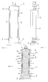
- Figures 1 to 3 show a more intricate insulator construction than the fibre glass core rod insulator mentioned above, but which is as well generally known to the skilled person and which doesn't need a detailed explanation here with the exception of the shed construction according to the present invention.
- the general construction of this insulator 1 includes the insulator flanges 2 and 3 made of metal and in particular made of aluminium.
- a stack 5 of varistor blocks is arranged between the flanges and is held by fibre reinforced bands 4 fixed to the flanges by screws 6 and 7.
- this construction is shown in general as an insert 8 of the completed insulator 1 on which the silicon rubber housing 9 is provided.
- the sheds 10, 10' extend from the housing.
- the silicon rubber sheds 10, 10' are shown in this example as being uniform with the housing 9 but may as well be separate parts made of silicone rubber that are arranged on a separate housing or are arranged directly on the insert.
- each disk or shed respectively, would exhibit a round circular circumferential outer shape, as it is usual with sheds, and a hollow middle part where the core or insert, respectively extends through the shed.
- each shed presents itself generally in the shape of a ring.
- Other outer shapes than round shapes are possible but would result in characteristics that are not uniform around the longitudinal axis L of the insulator and are thus rather avoided in practice.
- the inner ring shape of the sheds is of course adapted to the core or insert or housing shape, respectively.
- Figure 3 gives as well an example for the preferred "alternating" arrangement of the sheds along the longitudinal axis L which means that sheds of different diameter are following each other in longitudinal direction of the insulator.
- an alternating arrangement is preferred, arrangements of sheds of the same diameter are within the scope of the present invention, as well.
- a preferred shed distance or spacing between sheds, respectively is between 20 mm to 100 mm, preferably between 20 mm and 40 mm, but smaller and larger distances in vertical direction between sheds can be used on the insulator.
- the size of the sheds in horizontal direction is given by their diameter, but the term radius may be used below as well, denominating half of the diameter.
- the length of the part of the shed that actually protrudes from the cylindrical stem or inner ring part, respectively, of the disk-shaped shed can be used for defining the shed size in horizontal direction; this shed length can range from 10 mm to 200 mm, preferably can range from 10 mm to 100 mm. Diameters of the sheds of up to 500 mm or even more can be used but a preferred maximum size diameter is 200 mm or even 150 mm, combining good electrical characteristics with mechanical stability of the thin shed.
- the shed of the present invention has a tapered disk shape with a taper angle of less than or equal to 10° (or less than or equal to 6° in a preferred sub-range) and a curved free edge, as will be explained in greater detail below with reference to some special embodiments.
- the curved free or outer edge of the sheds is essentially of circular shape as seen in vertical section of the shed and has a radius of 0,1 mm or greater, and in particular of 0,2 mm or greater, and has a radius that is equal to or less than 2 mm, and in particular equal to or less than 1 mm, thus defining a range of 0,1 mm to 2 mm, and a preferred sub-range of 0,2 mm to 1 mm as the preferred round edge radius value of the sheds.
- both the upper side and the lower side of the sheds are tapered with respect to the horizontal plane, and it is preferred that the upper taper angle and the lower taper angle are of equal size.
- unequal taper angles may be used as well.
- a shed according to an embodiment of the invention may exhibit an upper tapered side (with a taper angle of 10° or less, or particularly 6° or less) while the lower side is not tapered and can thus be said to have a taper angle of 0° or can be said as lying horizontally.
- tapered surfaces of the sheds and thus their upper surface and their lower surface are each regular and flat, as shown in the vertical cuts of the sheds in the drawings.
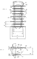
- Figures 4 and 5 show the preferred alternating shed arrangement, wherein for example sheds of a diameter d1 of 120 mm and sheds of a diameter d2 of 90 mm (a difference in 20%) alternate.
- the spacing s between sheds is for example selected as 20 mm.
- Figure 5 which shows detail A of Figure 4 and thus a part of a larger diameter shed 10 and a part of a smaller diameter shed 10' in an enlarged view compared to Figure 4 , these sheds are tapered on both sides.
- the taper angles are equal on both sides of horizontal planes H1 or H2, respectively, which "cut" sheds 10 and 10' in an upper and a lower half for explanation purposes in the drawing.
- the sheds 10 and 10' are symmetrical with regard to the planes H1 and H2, respectively.
- an upper shed taper angle of 2.05° and a lower shed taper angle of 2.05° result in a total taper angle alpha of 4.1° for these 120 mm radius sheds, which furthermore have a radius R1 of e.g. 0.65 mm for the rounded edge 11 of the shed.
- a preferred upper and lower shed angle of 2.95° each results in a total taper angle alpha of 5.9°, and an edge radius R2 of e.g. 0.8 mm may be provided on this shed.
- the tip or edge 11, 11' respectively, of the free or outer edge of the sheds 10 and 10' is round and, as seen in the vertical cut view of Figure 5 , is circular and with the mentioned radii; the shed edge may e.g. be round, parabolic or asymmetric in shape.
- the taper of the sheds according to such a preferred example is the same on both sides of the horizontal planes H1 and H2, respectively.
- the total taper angle alpha of the upper larger diameter shed is the sum of the taper angle of the upper side 13 of shed 10 with the horizontal plane H1 and of the taper angle between the lower side 14 of shed and the horizontal plane H1.
- the taper angles of the upper side 13 and of the lower side 14 with respect to the horizontal plane H1 are preferably of equal size, as is shown, but may as well be unequal, and the taper angle of the lower side 14 may be even 0° so that this side 14 is coplanar with plane H1.
- a part of such a shed 10 is shown in Figure 9 in vertical cut view and wherein the same reference numerals are used as for the other embodiments.
- the total taper angle of the sheds is equal to or less than 10° according to the present invention which results in the advantages explained above, and is in this example less than 6° which is even within the preferred sub-range.
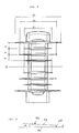
- Figures 6 and 7 show another alternating embodiment with sheds of three different diameters, wherein the uppermost and bottommost sheds 10 of insulator 1 have the largest diameter d1 and may have for example a diameter of 150 mm.
- a total shed angle alpha of 6.1° resulting from an upper and a lower shed angle of 3.05° each is provided, and an edge 11 radius R1 of e.g. 0.65 mm is present on the 150 mm radius shed 10.
- the same considerations as to the angle with regard to horizontal plane H1 of Figure 7 apply as in the example of Figures 4 and 5 above.
- the large uppermost shed of Figures 6 and 7 serves to protect the lower sheds during rainy periods, thus leaving a relatively large dry area along the length of the insulator.
- the large shed 10 also acts as a barrier for flashovers and increases creepage distance.
- the tip 11 curvature of shed 10 is preferably round, as well, and provided with the mentioned radius of preferably 0.65 mm.
- Shed 10' of this embodiment having the second largest diameter d2 may have a total taper angle alpha of 5.9° resulting from the two taper angles half this size of surfaces 13' and 14' with regard to the horizontal plane H2(as shed 10' in the example of Figure 5 ). Further an edge 11' radius R2 of e.g 0.8 mm is provided, giving a shed thickness directly adjacent to the curvature of 1.6 mm.
- Radius R3 edge radius is provided on edge 11" and may have a value of e.g. 0.65 mm, as well.
- FIG. 8 uses alternating sheds as with the example of Figures 6 and 7 , but shows that the preferred alternating shed design with a largest uppermost shed 10 of diameter d1 permits the removal of an inner shed while maintaining creepage distance along the insulator surface.
- Shed spacing in the middle is selected preferably as being double the shed spacing s between other sheds.
- the upper sheds are spaced 20 mm apart, as well as the lower sheds, but the two sheds 10" adjacent the middle horizontal plane H through the insulator are spaced 40 mm from each other.
- the values for the sheds of this example may be the same for taper angle and tip radius as in Figures 6 and 7 .
- the alternating thin shed design as described adheres to IEC 60815 recommendations, and values are thus preferably selected so that the ratios described in IEC 60815 are within the "white ranges" defined therein.
- the sheds and insulators described above and claimed perform well in polluted environments.
- a shed angle of equal or less than 10°, a shed tip radius of greater than 0.1 mm and in particular equal or greater 0.2 mm, but lower than 2 mm results in a material-saving shed with good electrical characteristics.
- For the insulator with such sheds an alternating arrangement of the sheds is preferred and a preferred shed distance of 20 mm -40 mm is used to produce the open design.
- the minimized design exhibits a small to zero increase in electric field at the shed tip (in the dry state) in comparison to sheds and insulators known in the prior art.
- the thin sheds perform well in moist and polluted environments.
- the reduced shed angle and tip radius allow for the dripping of rain while leaving the underside of the shed dry; long pendant drops, which may lead to flashover, are not observed.
- the creepage distance of the design is controlled by adjusting the shed radius.
- a preferred diameter not exceeding 150 mm with a shed thickness of for example 1.3 mm (round edge of shed with edge radius of 0.65 mm) is proposed in order to maintain the mechanical requirements of the shed under load (i.e. snow, ice, wind).
- An alternating design with a distance of 20 mm to 40 mm between sheds performs well in polluted environments; reduction in shed thickness allows for an increase in the openness of the design, and minimal collection of pollutants on the shed surfaces are observed.
- the open design allows for swift drying after rain and thus limited periods of dry band arcing occur.
- the inventive features result in reduced surface damage from arcing.
- the design is preferably symmetric; upside down installation of the finished part will not reduce the performance of the insulation in wet or polluted environments.
- Sheds may for example be moulded or extruded.
Landscapes
- Engineering & Computer Science (AREA)
- Microelectronics & Electronic Packaging (AREA)
- Physics & Mathematics (AREA)
- Electromagnetism (AREA)
- Insulators (AREA)
Abstract
Polymer sheds (10,10',10") and insulators (1) with such sheds (10,10',10") are described that perform well in polluted environments. A shed angle (α) of equal to or less than 10°, a shed tip (11,11') radius (R1,R2) of greater than 0.1 mm and in particular equal to or greater than 0.2 mm, but lower than 3 mm results in a material-saving shed with good electrical characteristics. For the insulator (1) with such sheds (10,10',10") an alternating arrangement of the sheds (10,10',10") is preferred and a preferred shed distance (s) is in the range of 20 mm - 40 mm. The minimized design exhibits a small to zero increase in electric field at the shed tip (11,11'), in the dry state, in comparison to sheds and insulators known in the prior art. The thin sheds (10,10',10") perform well in moist and polluted environments. The reduced shed angle (α) and tip radius (R1,R2) allow for the dripping of rain while leaving the underside of the shed dry; long pendant drops, which may lead to flashover, are not observed. The creepage distance of the design is controlled by adjusting the shed radius.
Description
- The invention resides in the field of electrical insulation, in particular for medium and high voltage technology. The invention relates to a shed for an electrical insulator. Further, the invention relates to an electrical insulator with a plurality of sheds.
- Electrical insulators for medium to high voltage apparatuses with a plurality of sheds are well known, for example as line insulators, as bushings, surge arresters, or, e.g., as insulators for current or voltage transformers or other high voltage equipment. Insulator shed design is influenced by the insulation material chosen, production technology, mounting of the insulator and the environment/pollution level to which the insulator will be exposed. A variety of shed designs are in use. IEC 60815-3 deals with the selection of insulators with polymer sheds to be used in high voltage AC (alternating current) systems and with respect of their behaviour under polluted conditions. Dirt, other types of pollution, salt and of course water on the surface of a high voltage insulator will create conductive paths, causing leakage currents and flashovers. Shed profile parameters shall avoid rain bridging and prevent local short circuit between sheds, aid in self cleaning to avoid localized pollutant accumulation, and keep the local electric field stresses within allowable limits. Despite the wide variety of shed designs, there is still room for improvement.
- Thus the invention aims at providing an improved shed design giving better characteristics for the shed and the insulator so equipped, in particular under polluted environmental condition.
- This goal is met by a shed which has a tapered disk shape with an angle of less than or equal to 10°, and in particular of less than and equal to 6.5°, and has a curved free end shape.
- It has been found that such sheds and insulators with such sheds perform well in polluted environments.
- A shed angle of equal to or less than 10°, or even in particular only equal to or less than 6.5°, combined in particular with a shed tip radius of greater than 0.1 mm, and in particular equal to or greater than 0.2 mm, but lower than 3mm, in particular less than 2 mm, preferably less than 1 mm, results in a preferred material-saving and thus cost-saving shed with very good electrical characteristics. For the insulator with such sheds an alternating arrangement of the sheds is preferred. The minimized design exhibits a small to zero increase in electric field at the shed tip (in the dry state) in comparison to sheds and insulators known in the art. The thin sheds perform well in moist and polluted environments. The reduced shed angle and tip radius allow for the dripping of rain while leaving the underside of the shed dry; long pendant drops, which may lead to flashover, are not observed. The creepage distance of the design is controlled by adjusting the shed diameter.
- The shed thus formed adheres preferably to IEC 60815 recommendations. The reduction in shed thickness compared to prior art sheds and insulators, respectively, allows for an increase in the openness of the structure, and a minimal collection of pollutants on the shed surfaces can be observed. The claimed structure allows for rapid and easy drying after rain, and thus limited periods of dry band arcing occur. The claimed structure shows diminished surface damage from arcing. The claimed geometry is well suited for moulding or extrusion of sheds.
- Preferably, all sheds of the insulator are sheds according to the invention. In special situations, these sheds may be combined with prior art sheds. Preferably, the shape of the shed is symmetric to a horizontal plane for a vertical mounting situation of the insulator equipped with the shed. As well preferred is a symmetric arrangement of the plurality of sheds on the insulator with regard to a central horizontal plane of the insulator (as well to be understood for a situation of vertical mounting of the insulator). This allows for upside down installation of the finished insulator without diminishing the performance of the insulation in wet or polluted environments.
- The creepage distance of the shed and insulator is controlled, in particular, by adjusting the length of the tapered shed part.
- The invention will be better understood and objects other than those set forth above will become apparent when consideration is given to the following detailed description thereof. Such description makes reference to the annexed drawing, wherein:
-
Figure 1 shows the inner construction feature of an example of an insulator in a frontal view; -
Figure 2 shows the construction ofFigure 1 in a side view; -
Figure 3 shows a vertical cross section of an insulator with polymer sheds according to an embodiment of the invention; -
Figure 4 shows another embodiment of an insulator with sheds according to the invention; -
Figure 5 shows parts of the sheds of the insulator ofFigure 4 ; -
Figure 6 shows another embodiment of an insulator with alternating sheds; -
Figure 7 shows sheds ofFigure 6 in detail; -
Figure 8 shows another insulator embodiment; and -
Figure 9 shows part of another shed embodiment. - Sheds according to the present invention can be provided on different types of insulators (including bushings) for medium to high voltages. The term medium to high voltage is here to be understood broadly to include voltages in the range of kilovolts, or even less, up to megavolts and does not imply a certain fixed range. The insulators can be of any construction. For example, the insulators are fibre glass core rod insulators, wherein a fibre glass core (full or hollow) is provided with silicon rubber sheds. The sheds may be arranged on the core either as single, previously moulded sheds with a silicone housing, which sheds are fitted on the core, or the sheds and silicone housing may be moulded or extruded directly on the core. The silicone housing should have a wall thickness between 0.2 mm and 15 mm. Such different production methods generally apply for the other types of insulators described below as well. In either case the sheds are made preferably from silicon rubber, and it is preferred that the silicon rubber is of the LSR type (LSR = Liquid Silicone Rubber) and HTV type (HTV = High Temperature Vulcanizing) that are well known to the skilled person. But RTV silicon rubber may be used as well (RTV = Room Temperature Vulcanizing). Other types of polymers that are applicable to insulators can be used as well.
- Although the term "shed" may imply a rather cup-shaped insulator part as in some prior art designs, the term is here used differently and in a very broad sense as a term for the tapered disk-shaped elements of the present invention that are not cup-shaped. Furthermore, the term "horizontal" and in particular "horizontal plane" used in this description has to be understood in view of a very common mounting situation of an insulator in which the longitudinal axis of the insulator lies in vertical direction (and the insulator is arranged standing or hanging) and a horizontal plane thus extends in a right angle to the longitudinal direction or axis, respectively, of the insulator provided with the sheds. The following definition of angles is made in respect to such horizontal planes. If the insulator would be mounted horizontally on the other hand, the taper angle values would be the same but with respect to a vertical plane. Of course, these insulators are as well suited for mounting of the whole insulator at other angles than vertical or horizontal mounting.
- As an example,
Figures 1 to 3 show a more intricate insulator construction than the fibre glass core rod insulator mentioned above, but which is as well generally known to the skilled person and which doesn't need a detailed explanation here with the exception of the shed construction according to the present invention. The general construction of thisinsulator 1 includes theinsulator flanges stack 5 of varistor blocks is arranged between the flanges and is held by fibre reinforcedbands 4 fixed to the flanges byscrews Figure 3 this construction is shown in general as aninsert 8 of the completedinsulator 1 on which thesilicon rubber housing 9 is provided. The sheds 10, 10' extend from the housing. The silicon rubber sheds 10, 10' are shown in this example as being uniform with thehousing 9 but may as well be separate parts made of silicone rubber that are arranged on a separate housing or are arranged directly on the insert. - Vertical cut view of the insulator of
Figure 3 gives a first general example of the sheds according to the present invention which are thintapered discs 10, 10' with acurved edge 11, 11'. If seen from above, each disk or shed, respectively, would exhibit a round circular circumferential outer shape, as it is usual with sheds, and a hollow middle part where the core or insert, respectively extends through the shed. Thus each shed presents itself generally in the shape of a ring. Other outer shapes than round shapes are possible but would result in characteristics that are not uniform around the longitudinal axis L of the insulator and are thus rather avoided in practice. The inner ring shape of the sheds is of course adapted to the core or insert or housing shape, respectively. -
Figure 3 gives as well an example for the preferred "alternating" arrangement of the sheds along the longitudinal axis L which means that sheds of different diameter are following each other in longitudinal direction of the insulator. Although an alternating arrangement is preferred, arrangements of sheds of the same diameter are within the scope of the present invention, as well. For an insulator of the present invention, being of alternating or non alternating construction, a preferred shed distance or spacing between sheds, respectively, is between 20 mm to 100 mm, preferably between 20 mm and 40 mm, but smaller and larger distances in vertical direction between sheds can be used on the insulator. - The size of the sheds in horizontal direction is given by their diameter, but the term radius may be used below as well, denominating half of the diameter. Instead of diameter or radius which relates to the ring shaped shed as a whole, the length of the part of the shed that actually protrudes from the cylindrical stem or inner ring part, respectively, of the disk-shaped shed can be used for defining the shed size in horizontal direction; this shed length can range from 10 mm to 200 mm, preferably can range from 10 mm to 100 mm. Diameters of the sheds of up to 500 mm or even more can be used but a preferred maximum size diameter is 200 mm or even 150 mm, combining good electrical characteristics with mechanical stability of the thin shed.
- In general the shed of the present invention has a tapered disk shape with a taper angle of less than or equal to 10° (or less than or equal to 6° in a preferred sub-range) and a curved free edge, as will be explained in greater detail below with reference to some special embodiments.
- In preferred embodiments, the curved free or outer edge of the sheds is essentially of circular shape as seen in vertical section of the shed and has a radius of 0,1 mm or greater, and in particular of 0,2 mm or greater, and has a radius that is equal to or less than 2 mm, and in particular equal to or less than 1 mm, thus defining a range of 0,1 mm to 2 mm, and a preferred sub-range of 0,2 mm to 1 mm as the preferred round edge radius value of the sheds. This gives a thickness of the shed directly adjacent the curved edge of 0,2 mm to 4 mm, and in particular 0,4 mm to 2 mm, which increases towards the stem or inner ring part, respectively, of the shed according to its taper angle.
- As will be explained, preferably both the upper side and the lower side of the sheds are tapered with respect to the horizontal plane, and it is preferred that the upper taper angle and the lower taper angle are of equal size. But unequal taper angles may be used as well. As a special case of the unequal taper angle a shed according to an embodiment of the invention may exhibit an upper tapered side (with a taper angle of 10° or less, or particularly 6° or less) while the lower side is not tapered and can thus be said to have a taper angle of 0° or can be said as lying horizontally.
- The tapered surfaces of the sheds and thus their upper surface and their lower surface are each regular and flat, as shown in the vertical cuts of the sheds in the drawings.
-
Figures 4 and 5 show the preferred alternating shed arrangement, wherein for example sheds of a diameter d1 of 120 mm and sheds of a diameter d2 of 90 mm (a difference in 20%) alternate. The spacing s between sheds is for example selected as 20 mm. As can be seen inFigure 5 which shows detail A ofFigure 4 and thus a part of a larger diameter shed 10 and a part of a smaller diameter shed 10' in an enlarged view compared toFigure 4 , these sheds are tapered on both sides. The taper angles are equal on both sides of horizontal planes H1 or H2, respectively, which "cut" sheds 10 and 10' in an upper and a lower half for explanation purposes in the drawing. Thus thesheds 10 and 10' are symmetrical with regard to the planes H1 and H2, respectively. Forsheds 10 an upper shed taper angle of 2.05° and a lower shed taper angle of 2.05° result in a total taper angle alpha of 4.1° for these 120 mm radius sheds, which furthermore have a radius R1 of e.g. 0.65 mm for therounded edge 11 of the shed. For the shed 10' of smaller diameter a preferred upper and lower shed angle of 2.95° each results in a total taper angle alpha of 5.9°, and an edge radius R2 of e.g. 0.8 mm may be provided on this shed. This leads to a shed thickness adjacent to the tip 11' of 1.6 mm. The thickness then increases towards the housing depending on the taper angle. - In this preferred embodiment the tip or
edge 11, 11' respectively, of the free or outer edge of thesheds 10 and 10' is round and, as seen in the vertical cut view ofFigure 5 , is circular and with the mentioned radii; the shed edge may e.g. be round, parabolic or asymmetric in shape. The taper of the sheds according to such a preferred example is the same on both sides of the horizontal planes H1 and H2, respectively. Thus, the total taper angle alpha of the upper larger diameter shed is the sum of the taper angle of theupper side 13 ofshed 10 with the horizontal plane H1 and of the taper angle between thelower side 14 of shed and the horizontal plane H1. As explained above, the taper angles of theupper side 13 and of thelower side 14 with respect to the horizontal plane H1 are preferably of equal size, as is shown, but may as well be unequal, and the taper angle of thelower side 14 may be even 0° so that thisside 14 is coplanar with plane H1. A part of such ashed 10 is shown inFigure 9 in vertical cut view and wherein the same reference numerals are used as for the other embodiments. - The total taper angle of the sheds is equal to or less than 10° according to the present invention which results in the advantages explained above, and is in this example less than 6° which is even within the preferred sub-range.
-
Figures 6 and 7 show another alternating embodiment with sheds of three different diameters, wherein the uppermost andbottommost sheds 10 ofinsulator 1 have the largest diameter d1 and may have for example a diameter of 150 mm. A total shed angle alpha of 6.1° resulting from an upper and a lower shed angle of 3.05° each is provided, and anedge 11 radius R1 of e.g. 0.65 mm is present on the 150 mm radius shed 10. The same considerations as to the angle with regard to horizontal plane H1 ofFigure 7 apply as in the example ofFigures 4 and 5 above. The large uppermost shed ofFigures 6 and 7 serves to protect the lower sheds during rainy periods, thus leaving a relatively large dry area along the length of the insulator. The large shed 10 also acts as a barrier for flashovers and increases creepage distance. Thetip 11 curvature of shed 10 is preferably round, as well, and provided with the mentioned radius of preferably 0.65 mm. - Shed 10' of this embodiment having the second largest diameter d2 may have a total taper angle alpha of 5.9° resulting from the two taper angles half this size of surfaces 13' and 14' with regard to the horizontal plane H2(as shed 10' in the example of
Figure 5 ). Further an edge 11' radius R2 of e.g 0.8 mm is provided, giving a shed thickness directly adjacent to the curvature of 1.6 mm. - For the
third shed type 10" of this embodiment with the diameter d3 a total taper angle of 4.1° is selected (with two equal upper and lower taper angles of half this size with regard to horizontal plane H3). Radius R3 edge radius is provided onedge 11" and may have a value of e.g. 0.65 mm, as well. - The further example of
Figure 8 uses alternating sheds as with the example ofFigures 6 and 7 , but shows that the preferred alternating shed design with a largest uppermost shed 10 of diameter d1 permits the removal of an inner shed while maintaining creepage distance along the insulator surface. Shed spacing in the middle is selected preferably as being double the shed spacing s between other sheds. For example the upper sheds are spaced 20 mm apart, as well as the lower sheds, but the twosheds 10" adjacent the middle horizontal plane H through the insulator are spaced 40 mm from each other. The values for the sheds of this example may be the same for taper angle and tip radius as inFigures 6 and 7 . - Thus the use of thin sheds as the result of the small edge radius values of
edges - It is preferred that the alternating thin shed design as described adheres to IEC 60815 recommendations, and values are thus preferably selected so that the ratios described in IEC 60815 are within the "white ranges" defined therein.
- The sheds and insulators described above and claimed perform well in polluted environments. A shed angle of equal or less than 10°, a shed tip radius of greater than 0.1 mm and in particular equal or greater 0.2 mm, but lower than 2 mm results in a material-saving shed with good electrical characteristics. For the insulator with such sheds an alternating arrangement of the sheds is preferred and a preferred shed distance of 20 mm -40 mm is used to produce the open design. The minimized design exhibits a small to zero increase in electric field at the shed tip (in the dry state) in comparison to sheds and insulators known in the prior art. The thin sheds perform well in moist and polluted environments. The reduced shed angle and tip radius allow for the dripping of rain while leaving the underside of the shed dry; long pendant drops, which may lead to flashover, are not observed. The creepage distance of the design is controlled by adjusting the shed radius. A preferred diameter not exceeding 150 mm with a shed thickness of for example 1.3 mm (round edge of shed with edge radius of 0.65 mm) is proposed in order to maintain the mechanical requirements of the shed under load (i.e. snow, ice, wind). An alternating design with a distance of 20 mm to 40 mm between sheds performs well in polluted environments; reduction in shed thickness allows for an increase in the openness of the design, and minimal collection of pollutants on the shed surfaces are observed. The open design allows for swift drying after rain and thus limited periods of dry band arcing occur. The inventive features result in reduced surface damage from arcing. Additionally, the design is preferably symmetric; upside down installation of the finished part will not reduce the performance of the insulation in wet or polluted environments. Such Sheds may for example be moulded or extruded.
Claims (17)
- Shed (10, 10', 10") for an electrical insulator (1), characterized in that the shed (10, 10', 10") has a tapered disk shape with a taper angle of less than or equal to 10°, or in particular of less than or equal to 6.5°, and has a curved shape of the free edge (11, 11', 11") of the shed.
- Shed (10, 10', 10") according to claim 1 characterized in that it comprises, in particular consists of, liquid silicone rubber or high temperature vulcanizing silicone rubber material.
- Shed (10, 10', 10") according to one of the preceding claims, characterized in that the curved free edge (11, 11', 11") has an essentially circular shape, in particular a circular shape, or has an essentially parabolic shape, in particular a parabolic shape, or has an asymmetric shape.
- Shed (10, 10', 10") according to one of the preceding claims, characterized in that the curved free edge (11, 11', 11") is essentially of circular shape and has a radius of 0,1 mm or greater, and in particular has a radius of 0,2 mm or greater.
- Shed (10, 10', 10") according to one of the preceding claims, characterized in that the edge (11, 11', 11") radius is less than 3 mm, in particular less than 2 mm, preferably less than 1 mm.
- Shed (10, 10', 10") according to one of the preceding claims, characterized in that the upper side (13, 13', 13") and the lower side (14, 14', 14") of the shed are tapered.
- Shed (10, 10', 10") according to claim 6, characterized in that the upper taper angle and the lower taper angle are of equal size.
- Shed (10, 10', 10") according to claim 6, characterized in that the upper taper angle and the lower taper angle are of unequal size.
- Shed (10, 10', 10") according to one of claims 1 to 5, characterized in that the upper side of the shed is tapered and the lower side is not tapered.
- Shed (10, 10', 10") according to one of the preceding claims, characterized in that the diameter of the shed is in the range of 10 mm to 500 mm, and in particular in the range of 10 mm to 200 mm.
- Shed (10, 10', 10") according to one of the preceding claims, characterized in that the shed length is in the range of 10 mm to 200 mm, in particular in the range of 10 mm to 100 mm.
- Electrical insulator (1) with a plurality of sheds (10, 10', 10") according to one of the preceding claims.
- Electrical insulator (1) according to claim 12, characterized that the sheds (10, 10', 10") have different diameters and are provided along the longitudinal axis of the insulator (1).
- Electrical insulator (1) according to claim 13, characterized in that the sheds (10, 10', 10") have two different shed diameters and are provided in an alternating arrangement along the longitudinal axis of the insulator (1).
- Electrical insulator (1) according to claim 13, characterized in that the sheds (10, 10', 10") have three different shed diameters which are provided in an alternating arrangement.
- Electrical insulator (1) according to claim 14 or 15, characterized in that an uppermost shed (10) and/or lowermost shed (10) is provided that has a greater diameter than the other sheds (11', 11").
- Electrical insulator (1) according to any of claims 13 to 16, characterized in that at least one shed is omitted in the middle of the insulator (1).
Priority Applications (1)
| Application Number | Priority Date | Filing Date | Title |
|---|---|---|---|
| EP10188584A EP2444982A1 (en) | 2010-10-22 | 2010-10-22 | Shed for an electrical insulator and insulator with a plurality of such sheds |
Applications Claiming Priority (1)
| Application Number | Priority Date | Filing Date | Title |
|---|---|---|---|
| EP10188584A EP2444982A1 (en) | 2010-10-22 | 2010-10-22 | Shed for an electrical insulator and insulator with a plurality of such sheds |
Publications (1)
| Publication Number | Publication Date |
|---|---|
| EP2444982A1 true EP2444982A1 (en) | 2012-04-25 |
Family
ID=43735177
Family Applications (1)
| Application Number | Title | Priority Date | Filing Date |
|---|---|---|---|
| EP10188584A Withdrawn EP2444982A1 (en) | 2010-10-22 | 2010-10-22 | Shed for an electrical insulator and insulator with a plurality of such sheds |
Country Status (1)
| Country | Link |
|---|---|
| EP (1) | EP2444982A1 (en) |
Cited By (5)
| Publication number | Priority date | Publication date | Assignee | Title |
|---|---|---|---|---|
| CN103472373A (en) * | 2013-08-27 | 2013-12-25 | 国家电网公司 | Method for evaluating external insulation equivalence of natural pollution insulator and artificial pollution insulator |
| WO2015067297A1 (en) | 2013-11-05 | 2015-05-14 | Abb Technology Ltd | Surge arrester with moulded sheds and apparatus for moulding |
| DE102017212391A1 (en) * | 2017-07-19 | 2019-01-24 | Siemens Aktiengesellschaft | Manufacturing process for electrical equipment and electrical equipment |
| US11490215B2 (en) | 2020-02-06 | 2022-11-01 | Sivantos Pte. Ltd. | Hearing aid |
| US11636960B2 (en) | 2018-08-30 | 2023-04-25 | Siemens Energy Global GmbH & Co. KG | Surge arrester and production method for a surge arrester |
Citations (6)
| Publication number | Priority date | Publication date | Assignee | Title |
|---|---|---|---|---|
| DE1078655B (en) * | 1958-07-23 | 1960-03-31 | Siemens Ag | Rotationally symmetrical high-voltage shield insulator, especially for outdoor systems |
| DE1119938B (en) * | 1957-07-19 | 1961-12-21 | Siemens Ag | Interior support isolator |
| DE1921299A1 (en) * | 1969-04-25 | 1970-11-12 | Rhein Westfael Isolatoren | Suspension insulator of glass fibre reinforced - plastic |
| US3786175A (en) * | 1971-04-27 | 1974-01-15 | Transmission Dev Ltd | Electrical insulator having sheds arranged at an angle to its axis |
| WO1997032317A1 (en) * | 1996-03-01 | 1997-09-04 | Cooper Industries, Inc. | Polymeric weathershed surge arrester and method |
| US20030217862A1 (en) * | 2002-03-27 | 2003-11-27 | Ngk Insulators, Ltd. | Polymer insulator |
-
2010
- 2010-10-22 EP EP10188584A patent/EP2444982A1/en not_active Withdrawn
Patent Citations (6)
| Publication number | Priority date | Publication date | Assignee | Title |
|---|---|---|---|---|
| DE1119938B (en) * | 1957-07-19 | 1961-12-21 | Siemens Ag | Interior support isolator |
| DE1078655B (en) * | 1958-07-23 | 1960-03-31 | Siemens Ag | Rotationally symmetrical high-voltage shield insulator, especially for outdoor systems |
| DE1921299A1 (en) * | 1969-04-25 | 1970-11-12 | Rhein Westfael Isolatoren | Suspension insulator of glass fibre reinforced - plastic |
| US3786175A (en) * | 1971-04-27 | 1974-01-15 | Transmission Dev Ltd | Electrical insulator having sheds arranged at an angle to its axis |
| WO1997032317A1 (en) * | 1996-03-01 | 1997-09-04 | Cooper Industries, Inc. | Polymeric weathershed surge arrester and method |
| US20030217862A1 (en) * | 2002-03-27 | 2003-11-27 | Ngk Insulators, Ltd. | Polymer insulator |
Cited By (6)
| Publication number | Priority date | Publication date | Assignee | Title |
|---|---|---|---|---|
| CN103472373A (en) * | 2013-08-27 | 2013-12-25 | 国家电网公司 | Method for evaluating external insulation equivalence of natural pollution insulator and artificial pollution insulator |
| WO2015067297A1 (en) | 2013-11-05 | 2015-05-14 | Abb Technology Ltd | Surge arrester with moulded sheds and apparatus for moulding |
| US9524815B2 (en) | 2013-11-05 | 2016-12-20 | Abb Schweiz Ag | Surge arrester with moulded sheds and apparatus for moulding |
| DE102017212391A1 (en) * | 2017-07-19 | 2019-01-24 | Siemens Aktiengesellschaft | Manufacturing process for electrical equipment and electrical equipment |
| US11636960B2 (en) | 2018-08-30 | 2023-04-25 | Siemens Energy Global GmbH & Co. KG | Surge arrester and production method for a surge arrester |
| US11490215B2 (en) | 2020-02-06 | 2022-11-01 | Sivantos Pte. Ltd. | Hearing aid |
Similar Documents
| Publication | Publication Date | Title |
|---|---|---|
| EP2444982A1 (en) | Shed for an electrical insulator and insulator with a plurality of such sheds | |
| CN101336458B (en) | Cage-type surge arrester | |
| CN108053958B (en) | A kind of arrester | |
| CN103270560B (en) | Transformer winding and transformer | |
| Albano et al. | Silicone rubber insulators for polluted environments part 2: textured insulators | |
| US9196396B2 (en) | Insulator and power transmission line apparatus | |
| JP2016033861A (en) | Capacitor bushing and method for producing the same | |
| US9524815B2 (en) | Surge arrester with moulded sheds and apparatus for moulding | |
| Shenoi et al. | Evaluating station post insulator performance from electric field calculations | |
| US7964268B2 (en) | Insulating structures | |
| CN203433910U (en) | Silicon-fluorine composite insulator with failure load being 300KN or 400KN | |
| CN202034132U (en) | Strut insulator of electric appliance for electric station with ultra-large creepage distance | |
| US3354262A (en) | Self-washing insulators | |
| CN201233770Y (en) | Rod type hanging porcelain insulator used in railway and electricity transmission and transforming equipments | |
| US20140345908A1 (en) | Device for reducing the corona effect | |
| CN108933059A (en) | A kind of mating insulated pull rod of indoor vacuum circuit breaker | |
| Albano et al. | Control of leakage-current and power dissipation by surface texturing of silicone rubber insulators | |
| US8901430B2 (en) | Cable termination for high-voltage cable application | |
| CN216902411U (en) | Corrosion-resistant polytetrafluoroethylene insulator | |
| RU156819U1 (en) | PIN INSULATOR | |
| RU86036U1 (en) | LINEAR SUSPENDING INSULATOR | |
| CN212258376U (en) | 35kV cable outdoor terminal special for offshore wind power | |
| CN2491949Y (en) | Disk-like suspension insulator with composite structure | |
| CN103123832B (en) | A kind of ultra-high/extra-high voltage exchanges umbrella structure of composite insulator | |
| CN108931710A (en) | A kind of post insulator style sensor |
Legal Events
| Date | Code | Title | Description |
|---|---|---|---|
| AK | Designated contracting states |
Kind code of ref document: A1 Designated state(s): AL AT BE BG CH CY CZ DE DK EE ES FI FR GB GR HR HU IE IS IT LI LT LU LV MC MK MT NL NO PL PT RO RS SE SI SK SM TR |
|
| AX | Request for extension of the european patent |
Extension state: BA ME |
|
| PUAI | Public reference made under article 153(3) epc to a published international application that has entered the european phase |
Free format text: ORIGINAL CODE: 0009012 |
|
| STAA | Information on the status of an ep patent application or granted ep patent |
Free format text: STATUS: THE APPLICATION IS DEEMED TO BE WITHDRAWN |
|
| 18D | Application deemed to be withdrawn |
Effective date: 20121026 |