EP2444683A1 - Clutch actuator and clutch provided with the same - Google Patents
Clutch actuator and clutch provided with the same Download PDFInfo
- Publication number
- EP2444683A1 EP2444683A1 EP10789204A EP10789204A EP2444683A1 EP 2444683 A1 EP2444683 A1 EP 2444683A1 EP 10789204 A EP10789204 A EP 10789204A EP 10789204 A EP10789204 A EP 10789204A EP 2444683 A1 EP2444683 A1 EP 2444683A1
- Authority
- EP
- European Patent Office
- Prior art keywords
- clutch actuator
- piston
- clutch
- peripheral surface
- way
- Prior art date
- Legal status (The legal status is an assumption and is not a legal conclusion. Google has not performed a legal analysis and makes no representation as to the accuracy of the status listed.)
- Withdrawn
Links
- 230000002093 peripheral effect Effects 0.000 claims abstract description 36
- 239000012530 fluid Substances 0.000 claims description 24
- 238000000465 moulding Methods 0.000 abstract description 3
- 239000002783 friction material Substances 0.000 description 13
- 230000005540 biological transmission Effects 0.000 description 8
- 238000010586 diagram Methods 0.000 description 1
- 230000000694 effects Effects 0.000 description 1
- 238000003466 welding Methods 0.000 description 1
Images


Classifications
-
- F—MECHANICAL ENGINEERING; LIGHTING; HEATING; WEAPONS; BLASTING
- F16—ENGINEERING ELEMENTS AND UNITS; GENERAL MEASURES FOR PRODUCING AND MAINTAINING EFFECTIVE FUNCTIONING OF MACHINES OR INSTALLATIONS; THERMAL INSULATION IN GENERAL
- F16D—COUPLINGS FOR TRANSMITTING ROTATION; CLUTCHES; BRAKES
- F16D25/00—Fluid-actuated clutches
- F16D25/08—Fluid-actuated clutches with fluid-actuated member not rotating with a clutching member
- F16D25/082—Fluid-actuated clutches with fluid-actuated member not rotating with a clutching member the line of action of the fluid-actuated members co-inciding with the axis of rotation
- F16D25/083—Actuators therefor
-
- F—MECHANICAL ENGINEERING; LIGHTING; HEATING; WEAPONS; BLASTING
- F16—ENGINEERING ELEMENTS AND UNITS; GENERAL MEASURES FOR PRODUCING AND MAINTAINING EFFECTIVE FUNCTIONING OF MACHINES OR INSTALLATIONS; THERMAL INSULATION IN GENERAL
- F16D—COUPLINGS FOR TRANSMITTING ROTATION; CLUTCHES; BRAKES
- F16D25/00—Fluid-actuated clutches
- F16D25/08—Fluid-actuated clutches with fluid-actuated member not rotating with a clutching member
-
- B—PERFORMING OPERATIONS; TRANSPORTING
- B60—VEHICLES IN GENERAL
- B60K—ARRANGEMENT OR MOUNTING OF PROPULSION UNITS OR OF TRANSMISSIONS IN VEHICLES; ARRANGEMENT OR MOUNTING OF PLURAL DIVERSE PRIME-MOVERS IN VEHICLES; AUXILIARY DRIVES FOR VEHICLES; INSTRUMENTATION OR DASHBOARDS FOR VEHICLES; ARRANGEMENTS IN CONNECTION WITH COOLING, AIR INTAKE, GAS EXHAUST OR FUEL SUPPLY OF PROPULSION UNITS IN VEHICLES
- B60K23/00—Arrangement or mounting of control devices for vehicle transmissions, or parts thereof, not otherwise provided for
- B60K23/02—Arrangement or mounting of control devices for vehicle transmissions, or parts thereof, not otherwise provided for for main transmission clutches
-
- F—MECHANICAL ENGINEERING; LIGHTING; HEATING; WEAPONS; BLASTING
- F16—ENGINEERING ELEMENTS AND UNITS; GENERAL MEASURES FOR PRODUCING AND MAINTAINING EFFECTIVE FUNCTIONING OF MACHINES OR INSTALLATIONS; THERMAL INSULATION IN GENERAL
- F16D—COUPLINGS FOR TRANSMITTING ROTATION; CLUTCHES; BRAKES
- F16D28/00—Electrically-actuated clutches
Definitions
- the present invention relates to the technical field of a clutch actuator that performs connection control and disconnection control of a clutch and to a clutch that is equipped with the clutch actuator.
- a clutch is configured to connect the output shaft of an engine and the input shaft of a transmission and also to disconnect the output shaft of the engine and the input shaft of the transmission.
- a clutch actuator is used in order to control the connection or the disconnection between the output shaft of the engine and the input shaft of the transmission.
- a clutch actuator where the output shaft of the engine and the input shaft of the transmission are connected as a result of a friction material that is attached to, in such a way as to be integrally rotatable with, the input shaft of the transmission being pushed by the biasing force of biasing means such as a diaphragm spring against a flywheel that is attached to, in such a way as to be integrally rotatable with, the output shaft of the engine and where the output shaft of the engine and the input shaft of the transmission are disconnected as a result of the biasing force of the biasing means being reduced or eliminated by fluid pressure is known in German Patent Application Publication DE 10323953 A1 .
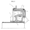
- FIG. 5 is a partial cross-sectional view in an axial direction of the clutch actuator described in DE 10323953 A1 .
- a clutch actuator a has: a housing d that includes an inner tube b and a case c; a piston g that is fitted together, in such a way as to be slidable in the axial direction and to be fluid-tight by means of a seal member e, between the outer peripheral surface of the inner tube b and the inner peripheral surface of a cylindrical portion of the case c and demarcates and forms a fluid actuation chamber f between itself and the housing d; and a release bearing h that is attached to, in such a way as to be integrally movable with, the piston g.
- the clutch actuator a is in the state shown in FIG. 5 when fluid pressure is not introduced to the fluid actuation chamber f, and the piston g is in a right limit position where it has most entered the housing d.
- the release bearing h does not strongly push an unillustrated diaphragm spring to the left, so an unillustrated friction material is pushed by the biasing force of the diaphragm spring against a similarly unillustrated flywheel, and the clutch a is in a connected state.
- foreign matter intrusion preventing means i is disposed in order to prevent foreign matter such as dirt existing on the outer peripheral side of the housing d from intruding into the inside of the housing d from between the inner peripheral surface of the cylindrical portion of the case c and the outer peripheral surface of a cylindrical portion of the piston g.
- This foreign matter intrusion preventing means i has a cylindrical cover j, which covers the outer peripheral surface of the cylindrical portion of the case c, and a seal member k, which is attached to the inner peripheral surface of this cover j and seals the inner peripheral surface of the cover j and the outer peripheral surface of the cylindrical portion of the case c.
- the cover j is attached to the piston g, and the cover j and the seal member k move integrally with this piston g together with the movement of the piston g.
- this conventional clutch actuator a uses the dedicated cover j as the foreign matter intrusion preventing means i, there are the problems that not only is the structure complex but the number of parts increases and the cost is high. Further, the inner tube b and the case c are formed separately and are joined to each other by welding or the like. For this reason, there are the problems that not only is a high-precision housing not obtained but processing becomes complicated. Moreover, the release bearing h is fixed to the piston g by means of a hook-like specially shaped stopper m.
- a clutch actuator pertaining to the present invention is a clutch including at least: a housing that has an inner cylinder and an outer cylinder; a piston that is fitted together, in such a way as to be fluid-tight and slidable, with the outer peripheral surface of the inner cylinder and the inner peripheral surface of the outer cylinder, demarcates and forms a fluid actuation chamber, and is actuated by fluid pressure of an actuation fluid that is introduced to the fluid actuation chamber; and a release bearing that is disposed on the piston in such a way as to be integrally movable with this piston and disconnects a clutch, wherein the housing is formed as a result of the inner cylinder and the outer cylinder being integrally molded as a single member, and foreign matter intrusion preventing means that prevents foreign matter from intruding into the inside of the fluid actuation chamber from between the inner peripheral surface of the outer cylinder and the piston is disposed on the outer cylinder.
- the foreign matter intrusion preventing means is a seal member that is disposed on the inner peripheral surface side of the outer cylinder.
- the release bearing is attached, in such a way as to be attachable and detachable by means of a snap ring , to the piston.
- a clutch of the present invention is a clutch including at least: a first shaft to which the output of a drive device is transmitted; a drive-side rotating member that is attached to the first shaft in such a way as to be integrally rotatable with this first shaft; a second shaft of a driven device that is driven by the output of the drive device; a driven-side rotating member that is attached to the second shaft in such a way as to be integrally rotatable with this second shaft and so as to be pushable against and separable from the drive-side rotating member; a driven-side rotating member pushing member that pushes the driven-side rotating member against the drive-side rotating member; and a clutch actuator that actuates and controls the driven-side rotating member pushing member, wherein the clutch actuator is any one of the clutch actuators of the present invention above.
- the foreign matter intrusion preventing means that prevents foreign matter from intruding into the inside of the fluid actuation chamber from between the inner peripheral surface of the outer cylinder and the piston is disposed on the outer cylinder. Consequently, the dedicated cover in the clutch actuator described in DE 10323953 A1 can be made unnecessary. As a result, the number of parts of the clutch actuator can be curtailed, the structure of the clutch actuator can be simplified, and the cost can be reduced in correspondence therewith. In particular, by using as the foreign matter intrusion preventing means the seal member that is disposed on the inner peripheral surface side of the outer cylinder, the structure of the clutch actuator can be even more effectively simplified.
- the inner cylinder and the outer cylinder are formed by the integral molding of a single member, so a high-precision housing can be obtained and processing can be simplified.
- the release bearing is attached, in such a way as to be attachable and detachable by means of the simply shaped snap ring, to the piston. Consequently, the attachment and detachment of the release bearing with respect to the piston becomes simple and the piston can be made into a simpler shape.
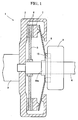
- FIG. 1 is a diagram schematically showing an example of a clutch equipped with an example of an embodiment of a clutch actuator pertaining to the present invention.
- a clutch 1 of this example is equipped with: an output shaft 2 (which corresponds to a first shaft of the present invention) to which the output of an engine (a drive device of the present invention) is transmitted; a flywheel 3 (which corresponds to a drive-side rotating member of the present invention) that is connected to, in such a way as to be integrally rotatable with, this output shaft 2; an input shaft 4 (which corresponds to a second shaft of the present invention) of a transmission that is a driven device that is driven by the output of the engine; a friction material 6 (which corresponds to a driven-side rotating member of the present invention) that is connected to, in such a way as to be integrally rotatable with, the input shaft 4 via a disc-shaped support member 5; a friction material pushing member 7 that pushes the friction material 6 against the flywheel 3; a diaphragm spring 8 that is biasing means that biases this friction material pushing member 7 in such a way that the friction material pushing member
- FIG. 2 is a cross-sectional view along an axial direction showing the clutch actuator at a time of non-actuation in this example
- FIG. 3 is a cross-sectional view along the axial direction showing the clutch actuator at a time of actuation in this example.
- the clutch actuator 9 of this example has a housing 10 that is formed as a result of an inner tube 10a (which corresponds to an inner cylinder of the present invention) and a case 10b that has a cylindrical portion 10b 1 (which corresponds to an outer cylinder of the present invention) being integrally molded as a single member.
- the inner tube 10a and the cylindrical portion 10b 1 are disposed concentrically.
- a piston 11 is disposed in such a way as to be slidable between the outer peripheral surface of the inner tube 10a and the inner peripheral surface of the cylindrical portion 10b 1 of the case 10b.
- the piston 11 is fitted together, in such a way as to be fluid-tight by means of an annular seal member 12, with the outer peripheral surface of the inner tube 10a and is configured to be movable in the axial direction (the left-and-right direction in FIG. 2 ) on this inner tube 10a while being guided on the inner tube 10a. Further, the piston 11 is fitted together, in such a way as to be fluid-tight by means of an annular seal member 13, with the inner peripheral surface of the cylindrical portion 10b 1 of the case 10b. Because of this, a fluid actuation chamber 14 is demarcated and formed between the piston 11 and the housing 10.
- a release bearing 15 is disposed on the piston 11.
- This release bearing 15 is attached to the piston 11 in such a way as to be attachable and detachable by means of a snap ring 16. Additionally, the release bearing 15 strongly pushes the diaphragm spring 8 to the left as a result of the movement of the piston 11 to the left in FIG. 2 .
- the piston 11 is always biased, by a coil spring 17 that is biasing means, in the direction in which the release bearing 15 pushes the diaphragm spring 8.
- the biasing force of the diaphragm spring 8 that pushes the release bearing 15 and the piston 11 to the right is set to be larger than the biasing force of the coil spring 17 that pushes the piston 11 and the release bearing 15 to the left. Consequently, in the non-actuated state of the clutch actuator 9 shown in FIG. 2 where fluid pressure is not introduced into the fluid actuation chamber 14, the piston 11 most enters the inside of the housing 10 and is positioned in a right limit position.
- annular seal member 18 that is foreign matter intrusion preventing means is disposed on the inner peripheral surface of the cylindrical portion 10b 1 of the housing 10.
- the seal member 18 is disposed in a seal member accommodating portion 19, which is disposed on the axial direction end portion of the cylindrical portion 10b 1 and projects from the outer peripheral surface of the cylindrical portion 10b 1 in such a way that the inner peripheral surface of the cylindrical portion 10b 1 becomes recessed.
- the seal member accommodating portion 19-that is, the seal member 18- is disposed further toward the open end side of the cylindrical portion 10b 1 than the seal member 13. This seal member 18 prevents foreign matter such as dirt existing on the outer peripheral side of the housing 10 from intruding toward the fluid actuation chamber 14 from between the inner peripheral surface of the cylindrical portion 10b 1 of the housing 10 and the outer peripheral surface of the piston 11.
- the clutch actuator 9 and the clutch 1 of this example only the seal member 18 disposed on the inner peripheral surface of the cylindrical portion 10b 1 of the case 10 is used as the foreign matter intrusion preventing means. Consequently, the dedicated cover in the clutch actuator described in DE 10323953 A1 can be made unnecessary. As a result, the number of parts of the clutch actuator 9 can be curtailed, the structure of the clutch actuator 9 can be simplified, and the cost can be reduced in correspondence therewith. In particular, by using the seal member 18 as the foreign matter intrusion preventing means, the structure of the clutch actuator 9 can be even more effectively simplified.
- the inner tube 10a and the case 10b are formed by the integral molding of a single member, so a high-precision housing can be obtained and processing can be simplified.
- the release bearing 15 is attached, in such a way as to be attachable and detachable by means of the simply shaped snap ring 16, to the piston 11. Consequently, the attachment and detachment of the release bearing 15 with respect to the piston 11 becomes simple and the piston 11 can be made into a simpler shape.
- FIG. 4 is a cross-sectional view that is the same as FIG. 2 and shows another example of the embodiment of the clutch actuator pertaining to the present invention.
- the seal member 18 is disposed on the inner peripheral surface of the cylindrical portion 10b 1 of the case 10b, but as shown in FIG. 4 , in the clutch actuator 9 of this example, the seal member 18 is disposed on the outer peripheral surface of the piston 11. In that instance, the seal member 18 is disposed on the outer peripheral surface of the piston that slides on the inner peripheral surface of the cylindrical portion 10b 1 even in a state where the piston 11 has maximally moved. In this way, because the seal member 18 is disposed on the piston 11, the seal member accommodating portion 19 of the above example that is disposed on the cylindrical portion 10b 1 can be made unnecessary. Because of this, the shape of the case 10b becomes simple and the processing of the housing 10 becomes easy. Further, in the example shown in FIG.
- annular flange 10b 2 is disposed on the open end of the cylindrical portion 10b 1 , but this flange 10b 2 can also be omitted.
- the clutch actuator pertaining to the present invention and the clutch equipped with the clutch actuator can be utilized in a clutch actuator that performs connection control and disconnection control of a clutch and in a clutch that is equipped with the clutch actuator, and in particular can be suitably used in a clutch actuator that is actuated by fluid pressure and a clutch that is equipped with the clutch actuator.
Landscapes
- Engineering & Computer Science (AREA)
- General Engineering & Computer Science (AREA)
- Mechanical Engineering (AREA)
- Physics & Mathematics (AREA)
- Electromagnetism (AREA)
- Chemical & Material Sciences (AREA)
- Combustion & Propulsion (AREA)
- Transportation (AREA)
- Hydraulic Clutches, Magnetic Clutches, Fluid Clutches, And Fluid Joints (AREA)
- Mechanical Operated Clutches (AREA)
Abstract
A clutch actuator (9) of the present invention includes a housing (10) that is formed by integrally molding an inner tube (10a) and a case (10b) as a single member. Further, a seal member (18) that is foreign matter intrusion preventing means is disposed on the inner peripheral surface of a cylindrical portion (10b1) of the case (10b). Moreover, a release bearing (15) is attached, in such a way as to be attachable and detachable by means of a snap ring (16), to a piston (11). Because of this, there is realized a high-precision, inexpensive clutch actuator (9) whose structure is simplified, whose number of parts is reduced, and in which the attachment and detachment of the release bearing (15) becomes easy.
Description
- The present invention relates to the technical field of a clutch actuator that performs connection control and disconnection control of a clutch and to a clutch that is equipped with the clutch actuator.
- Conventionally, a clutch is configured to connect the output shaft of an engine and the input shaft of a transmission and also to disconnect the output shaft of the engine and the input shaft of the transmission. Usually, in such a clutch, a clutch actuator is used in order to control the connection or the disconnection between the output shaft of the engine and the input shaft of the transmission.
- As a conventional clutch actuator, a clutch actuator where the output shaft of the engine and the input shaft of the transmission are connected as a result of a friction material that is attached to, in such a way as to be integrally rotatable with, the input shaft of the transmission being pushed by the biasing force of biasing means such as a diaphragm spring against a flywheel that is attached to, in such a way as to be integrally rotatable with, the output shaft of the engine and where the output shaft of the engine and the input shaft of the transmission are disconnected as a result of the biasing force of the biasing means being reduced or eliminated by fluid pressure is known in German Patent Application Publication
DE 10323953 A1 . -
FIG. 5 is a partial cross-sectional view in an axial direction of the clutch actuator described inDE 10323953 A1 . As shown inFIG. 5 , a clutch actuator a has: a housing d that includes an inner tube b and a case c; a piston g that is fitted together, in such a way as to be slidable in the axial direction and to be fluid-tight by means of a seal member e, between the outer peripheral surface of the inner tube b and the inner peripheral surface of a cylindrical portion of the case c and demarcates and forms a fluid actuation chamber f between itself and the housing d; and a release bearing h that is attached to, in such a way as to be integrally movable with, the piston g. - Additionally, the clutch actuator a is in the state shown in
FIG. 5 when fluid pressure is not introduced to the fluid actuation chamber f, and the piston g is in a right limit position where it has most entered the housing d. In this state, the release bearing h does not strongly push an unillustrated diaphragm spring to the left, so an unillustrated friction material is pushed by the biasing force of the diaphragm spring against a similarly unillustrated flywheel, and the clutch a is in a connected state. - When fluid pressure is introduced to the fluid actuation chamber f, the piston g moves to the left while being guided on the inner tube b, and the release bearing h strongly pushes the diaphragm spring to the left. Because of this, the biasing force of the diaphragm spring is reduced or eliminated, so the friction material is not pushed against the flywheel and the clutch a enters a disconnected state.
- Incidentally, in the clutch actuator a described in
DE 10323953 A1 , foreign matter intrusion preventing means i is disposed in order to prevent foreign matter such as dirt existing on the outer peripheral side of the housing d from intruding into the inside of the housing d from between the inner peripheral surface of the cylindrical portion of the case c and the outer peripheral surface of a cylindrical portion of the piston g. This foreign matter intrusion preventing means i has a cylindrical cover j, which covers the outer peripheral surface of the cylindrical portion of the case c, and a seal member k, which is attached to the inner peripheral surface of this cover j and seals the inner peripheral surface of the cover j and the outer peripheral surface of the cylindrical portion of the case c. The cover j is attached to the piston g, and the cover j and the seal member k move integrally with this piston g together with the movement of the piston g. - However, because this conventional clutch actuator a uses the dedicated cover j as the foreign matter intrusion preventing means i, there are the problems that not only is the structure complex but the number of parts increases and the cost is high. Further, the inner tube b and the case c are formed separately and are joined to each other by welding or the like. For this reason, there are the problems that not only is a high-precision housing not obtained but processing becomes complicated. Moreover, the release bearing h is fixed to the piston g by means of a hook-like specially shaped stopper m. For this reason, it is necessary to form this specially shaped stopper m on the piston g, and there are the problems that not only is the shape of the piston g complex but the attachment and detachment of the release bearing h with respect to the piston g is troublesome.
- It is an object of the present invention to provide: a high-precision inexpensive clutch actuator whose structure is simplified, whose number of parts is reduced, and in which the attachment and detachment of the release bearing can be done simply; and a clutch equipped with the clutch actuator.
- In order to achieve this object, a clutch actuator pertaining to the present invention is a clutch including at least: a housing that has an inner cylinder and an outer cylinder; a piston that is fitted together, in such a way as to be fluid-tight and slidable, with the outer peripheral surface of the inner cylinder and the inner peripheral surface of the outer cylinder, demarcates and forms a fluid actuation chamber, and is actuated by fluid pressure of an actuation fluid that is introduced to the fluid actuation chamber; and a release bearing that is disposed on the piston in such a way as to be integrally movable with this piston and disconnects a clutch, wherein the housing is formed as a result of the inner cylinder and the outer cylinder being integrally molded as a single member, and foreign matter intrusion preventing means that prevents foreign matter from intruding into the inside of the fluid actuation chamber from between the inner peripheral surface of the outer cylinder and the piston is disposed on the outer cylinder.
- Further, in the clutch actuator pertaining to the present invention, the foreign matter intrusion preventing means is a seal member that is disposed on the inner peripheral surface side of the outer cylinder.
- Moreover, in the clutch actuator pertaining to the present invention, the release bearing is attached, in such a way as to be attachable and detachable by means of a snap ring , to the piston.
- A clutch of the present invention is a clutch including at least: a first shaft to which the output of a drive device is transmitted; a drive-side rotating member that is attached to the first shaft in such a way as to be integrally rotatable with this first shaft; a second shaft of a driven device that is driven by the output of the drive device; a driven-side rotating member that is attached to the second shaft in such a way as to be integrally rotatable with this second shaft and so as to be pushable against and separable from the drive-side rotating member; a driven-side rotating member pushing member that pushes the driven-side rotating member against the drive-side rotating member; and a clutch actuator that actuates and controls the driven-side rotating member pushing member, wherein the clutch actuator is any one of the clutch actuators of the present invention above.
- According to the clutch actuator and the clutch of the present invention that are configured in this way, the foreign matter intrusion preventing means that prevents foreign matter from intruding into the inside of the fluid actuation chamber from between the inner peripheral surface of the outer cylinder and the piston is disposed on the outer cylinder. Consequently, the dedicated cover in the clutch actuator described in
DE 10323953 A1 can be made unnecessary. As a result, the number of parts of the clutch actuator can be curtailed, the structure of the clutch actuator can be simplified, and the cost can be reduced in correspondence therewith. In particular, by using as the foreign matter intrusion preventing means the seal member that is disposed on the inner peripheral surface side of the outer cylinder, the structure of the clutch actuator can be even more effectively simplified. - Further, the inner cylinder and the outer cylinder are formed by the integral molding of a single member, so a high-precision housing can be obtained and processing can be simplified.
- Moreover, the release bearing is attached, in such a way as to be attachable and detachable by means of the simply shaped snap ring, to the piston. Consequently, the attachment and detachment of the release bearing with respect to the piston becomes simple and the piston can be made into a simpler shape.
-
-
FIG. 1 is a view schematically showing an example of a clutch equipped with an example of an embodiment of a clutch actuator pertaining to the present invention; -
FIG. 2 is a cross-sectional view along an axial direction showing the clutch actuator at a time of non-actuation in the example shown inFIG. 1 ; -
FIG. 3 is a cross-sectional view along the axial direction showing the clutch actuator at a time of actuation in the example shown inFIG. 1 ; -
FIG. 4 is a cross-sectional view that is the same asFIG. 2 and shows another example of the embodiment of the clutch actuator pertaining to the present invention; and -
FIG. 5 is a partial cross-sectional view in an axial direction of a clutch actuator described inDE 10323953 A1 . - Best modes for carrying out the present invention will be described below with reference to the drawings.
-
FIG. 1 is a diagram schematically showing an example of a clutch equipped with an example of an embodiment of a clutch actuator pertaining to the present invention. - As shown in
FIG. 1 , aclutch 1 of this example is equipped with: an output shaft 2 (which corresponds to a first shaft of the present invention) to which the output of an engine (a drive device of the present invention) is transmitted; a flywheel 3 (which corresponds to a drive-side rotating member of the present invention) that is connected to, in such a way as to be integrally rotatable with, thisoutput shaft 2; an input shaft 4 (which corresponds to a second shaft of the present invention) of a transmission that is a driven device that is driven by the output of the engine; a friction material 6 (which corresponds to a driven-side rotating member of the present invention) that is connected to, in such a way as to be integrally rotatable with, theinput shaft 4 via a disc-shaped support member 5; a frictionmaterial pushing member 7 that pushes thefriction material 6 against theflywheel 3; adiaphragm spring 8 that is biasing means that biases this frictionmaterial pushing member 7 in such a way that the frictionmaterial pushing member 7 pushes thefriction material 6; and aclutch actuator 9 that controls thisdiaphragm spring 8 . Theoutput shaft 2 andflywheel 3 and theinput shaft 4 are configured in such a way that they may freely rotate relative to each other. - As for the components of the
clutch 1 other than theclutch actuator 9, conventionally publicly-known components can be used, so detailed description of those will be omitted and theclutch actuator 9 that is the direct target of the present invention will be described below. -
FIG. 2 is a cross-sectional view along an axial direction showing the clutch actuator at a time of non-actuation in this example, andFIG. 3 is a cross-sectional view along the axial direction showing the clutch actuator at a time of actuation in this example. - As shown in
FIG. 2 , theclutch actuator 9 of this example has ahousing 10 that is formed as a result of aninner tube 10a (which corresponds to an inner cylinder of the present invention) and acase 10b that has acylindrical portion 10b1 (which corresponds to an outer cylinder of the present invention) being integrally molded as a single member. In that instance, theinner tube 10a and thecylindrical portion 10b1 are disposed concentrically. Further, like the clutch actuator described inDE 10323953 A1 , apiston 11 is disposed in such a way as to be slidable between the outer peripheral surface of theinner tube 10a and the inner peripheral surface of thecylindrical portion 10b1 of thecase 10b. In that instance, thepiston 11 is fitted together, in such a way as to be fluid-tight by means of anannular seal member 12, with the outer peripheral surface of theinner tube 10a and is configured to be movable in the axial direction (the left-and-right direction inFIG. 2 ) on thisinner tube 10a while being guided on theinner tube 10a. Further, thepiston 11 is fitted together, in such a way as to be fluid-tight by means of anannular seal member 13, with the inner peripheral surface of thecylindrical portion 10b1 of thecase 10b. Because of this, afluid actuation chamber 14 is demarcated and formed between thepiston 11 and thehousing 10. - A release bearing 15 is disposed on the
piston 11. This release bearing 15 is attached to thepiston 11 in such a way as to be attachable and detachable by means of asnap ring 16. Additionally, the release bearing 15 strongly pushes thediaphragm spring 8 to the left as a result of the movement of thepiston 11 to the left inFIG. 2 . Moreover, thepiston 11 is always biased, by acoil spring 17 that is biasing means, in the direction in which the release bearing 15 pushes thediaphragm spring 8. In that instance, in a state where theclutch 9 is installed between the engine and the transmission, the biasing force of thediaphragm spring 8 that pushes the release bearing 15 and thepiston 11 to the right is set to be larger than the biasing force of thecoil spring 17 that pushes thepiston 11 and the release bearing 15 to the left. Consequently, in the non-actuated state of theclutch actuator 9 shown inFIG. 2 where fluid pressure is not introduced into thefluid actuation chamber 14, thepiston 11 most enters the inside of thehousing 10 and is positioned in a right limit position. - Moreover, an
annular seal member 18 that is foreign matter intrusion preventing means is disposed on the inner peripheral surface of thecylindrical portion 10b1 of thehousing 10. In that instance, theseal member 18 is disposed in a sealmember accommodating portion 19, which is disposed on the axial direction end portion of thecylindrical portion 10b1 and projects from the outer peripheral surface of thecylindrical portion 10b1 in such a way that the inner peripheral surface of thecylindrical portion 10b1 becomes recessed. Further, the seal member accommodating portion 19-that is, the seal member 18-is disposed further toward the open end side of thecylindrical portion 10b1 than theseal member 13. Thisseal member 18 prevents foreign matter such as dirt existing on the outer peripheral side of thehousing 10 from intruding toward thefluid actuation chamber 14 from between the inner peripheral surface of thecylindrical portion 10b1 of thehousing 10 and the outer peripheral surface of thepiston 11. - The operation of the
clutch actuator 9 of this example will be described.
In the non-actuated state of theclutch actuator 9 shown inFIG. 2 , as mentioned above, thepiston 11 is in the right limit position. In this state of thepiston 11, the release bearing 15 does not strongly push thediaphragm spring 8 to the left. Consequently, as mentioned above, the frictionmaterial pushing member 7 pushes thefriction material 6 against theflywheel 3 because of the biasing force of thediaphragm spring 8. Because of this, theclutch 1 is in a connected state. - Further, when fluid pressure is introduced to the
fluid actuation chamber 14, as shown inFIG. 3 , thepiston 11 moves to the left while being guided on theinner tube 10a, and the release bearing 15 strongly pushes thediaphragm spring 8 to the left. Because of this, the pushing force of thediaphragm spring 8 on the frictionmaterial pushing member 7 is reduced or eliminated, and thefriction material 6 is not pushed against theflywheel 3. Because of this, theclutch 1 enters a disconnected state. - According to the
clutch actuator 9 and theclutch 1 of this example, only theseal member 18 disposed on the inner peripheral surface of thecylindrical portion 10b1 of thecase 10 is used as the foreign matter intrusion preventing means. Consequently, the dedicated cover in the clutch actuator described inDE 10323953 A1 can be made unnecessary. As a result, the number of parts of theclutch actuator 9 can be curtailed, the structure of theclutch actuator 9 can be simplified, and the cost can be reduced in correspondence therewith. In particular, by using theseal member 18 as the foreign matter intrusion preventing means, the structure of theclutch actuator 9 can be even more effectively simplified. - Further, the
inner tube 10a and thecase 10b are formed by the integral molding of a single member, so a high-precision housing can be obtained and processing can be simplified. Moreover, the release bearing 15 is attached, in such a way as to be attachable and detachable by means of the simply shapedsnap ring 16, to thepiston 11. Consequently, the attachment and detachment of the release bearing 15 with respect to thepiston 11 becomes simple and thepiston 11 can be made into a simpler shape. - The other configurations and the other action and effects of the
clutch actuator 9 of this example are the same as those of the clutch actuator described inDE 10323953 A1 . -
FIG. 4 is a cross-sectional view that is the same asFIG. 2 and shows another example of the embodiment of the clutch actuator pertaining to the present invention. - In the example above, the
seal member 18 is disposed on the inner peripheral surface of thecylindrical portion 10b1 of thecase 10b, but as shown inFIG. 4 , in theclutch actuator 9 of this example, theseal member 18 is disposed on the outer peripheral surface of thepiston 11. In that instance, theseal member 18 is disposed on the outer peripheral surface of the piston that slides on the inner peripheral surface of thecylindrical portion 10b1 even in a state where thepiston 11 has maximally moved. In this way, because theseal member 18 is disposed on thepiston 11, the sealmember accommodating portion 19 of the above example that is disposed on thecylindrical portion 10b1 can be made unnecessary. Because of this, the shape of thecase 10b becomes simple and the processing of thehousing 10 becomes easy. Further, in the example shown inFIG. 4 , anannular flange 10b2 is disposed on the open end of thecylindrical portion 10b1, but thisflange 10b2 can also be omitted. By doing this, the shape of thecase 10b becomes even simpler, the processing of thehousing 10 becomes even easier, and interference with another member does not have to be taken into consideration because no projecting portion exists on the outer peripheral surface of thecylindrical portion 10b1. - The present invention is not limited to the above examples and is capable of various design changes in the scope of matters set forth in the claims.
- The clutch actuator pertaining to the present invention and the clutch equipped with the clutch actuator can be utilized in a clutch actuator that performs connection control and disconnection control of a clutch and in a clutch that is equipped with the clutch actuator, and in particular can be suitably used in a clutch actuator that is actuated by fluid pressure and a clutch that is equipped with the clutch actuator.
Claims (4)
- A clutch actuator comprising at least:a housing that has an inner cylinder and an outer cylinder;a piston that is fitted together, in such a way as to be fluid-tight and slidable, with the outer peripheral surface of the inner cylinder and the inner peripheral surface of the outer cylinder, demarcates and forms a fluid actuation chamber, and is actuated by fluid pressure of an actuation fluid that is introduced to the fluid actuation chamber; anda release bearing that is disposed on the piston in such a way as to be integrally movable with this piston and disconnects a clutch,whereinthe housing is formed as a result of the inner cylinder and the outer cylinder being integrally molded as a single member, andforeign matter intrusion preventing means that prevents foreign matter from intruding into the inside of the fluid actuation chamber from between the inner peripheral surface of the outer cylinder and the piston is disposed on the outer cylinder.
- The clutch actuator according to claim 1, wherein the foreign matter intrusion preventing means is a seal member that is disposed on the inner peripheral surface side of the outer cylinder.
- The clutch actuator according to claim 1 or 2, wherein the release bearing is attached, in such a way as to be attachable and detachable by means of a snap ring , to the piston.
- A clutch comprising at least:a first shaft to which the output of a drive device is transmitted;a drive-side rotating member that is attached to the first shaft in such a way as to be integrally rotatable with this first shaft;a second shaft of a driven device that is driven by the output of the drive device;a driven-side rotating member that is attached to the second shaft in such a way as to be integrally rotatable with this second shaft and so as to be pushable against and separable from the drive-side rotating member;a driven-side rotating member pushing member that pushes the driven-side rotating member against the drive-side rotating member; anda clutch actuator that actuates and controls the driven-side rotating member pushing member,wherein the clutch actuator is the clutch actuator according to any one of claims 1 to 3.
Applications Claiming Priority (2)
| Application Number | Priority Date | Filing Date | Title |
|---|---|---|---|
| JP2009141968 | 2009-06-15 | ||
| PCT/JP2010/003926 WO2010146822A1 (en) | 2009-06-15 | 2010-06-14 | Clutch actuator and clutch provided with the same |
Publications (1)
| Publication Number | Publication Date |
|---|---|
| EP2444683A1 true EP2444683A1 (en) | 2012-04-25 |
Family
ID=43356155
Family Applications (1)
| Application Number | Title | Priority Date | Filing Date |
|---|---|---|---|
| EP10789204A Withdrawn EP2444683A1 (en) | 2009-06-15 | 2010-06-14 | Clutch actuator and clutch provided with the same |
Country Status (5)
| Country | Link |
|---|---|
| EP (1) | EP2444683A1 (en) |
| JP (1) | JPWO2010146822A1 (en) |
| KR (1) | KR101342426B1 (en) |
| CN (1) | CN102459940A (en) |
| WO (1) | WO2010146822A1 (en) |
Cited By (1)
| Publication number | Priority date | Publication date | Assignee | Title |
|---|---|---|---|---|
| CN115076251A (en) * | 2022-07-11 | 2022-09-20 | 青岛科麟智传汽车科技有限公司 | A commercial vehicle integrated clutch drive device |
Families Citing this family (8)
| Publication number | Priority date | Publication date | Assignee | Title |
|---|---|---|---|---|
| KR101897303B1 (en) * | 2013-10-10 | 2018-09-11 | 현대건설기계 주식회사 | Apparatus for Parking Brake of Construction Machinery |
| KR101600918B1 (en) | 2014-09-23 | 2016-03-08 | 주식회사 인팩 | Clutch actuator |
| KR101710938B1 (en) * | 2016-09-22 | 2017-02-28 | (주)에너토크 | Valve actuator |
| CN106640899A (en) * | 2016-12-28 | 2017-05-10 | 安徽六国化工股份有限公司 | Axial locking device used in pneumatic clutch |
| JP6802120B2 (en) * | 2017-07-26 | 2020-12-16 | 株式会社エクセディ | Clutch release device |
| DE102019208470A1 (en) * | 2019-06-11 | 2020-12-17 | Aktiebolaget Skf | Sealed clutch thrust bearing device and drive shaft system with such a device |
| CN114981555B (en) * | 2019-12-27 | 2025-10-24 | 驱动系统有限公司 | Transmission module with hydraulic actuator |
| KR102284510B1 (en) * | 2020-01-31 | 2021-07-30 | 주식회사평화발레오 | Concentric Clutch Actuator |
Family Cites Families (10)
| Publication number | Priority date | Publication date | Assignee | Title |
|---|---|---|---|---|
| JPS5360300U (en) * | 1976-10-22 | 1978-05-23 | ||
| JPH0134985Y2 (en) * | 1984-11-20 | 1989-10-25 | ||
| US4938332A (en) * | 1988-08-30 | 1990-07-03 | Federal-Mogul Corporation | Hydraulically actuated clutch release mechanism |
| JPH053778Y2 (en) * | 1988-11-09 | 1993-01-29 | ||
| DE4407665B4 (en) * | 1994-03-09 | 2005-09-22 | Zf Sachs Ag | Hydraulically actuated release system |
| JP3728481B2 (en) * | 1997-01-31 | 2005-12-21 | 光洋精工株式会社 | Hydraulic clutch breaker |
| JP2000274454A (en) * | 1999-03-25 | 2000-10-03 | Aisin Seiki Co Ltd | Clutch operating cylinder device with stroke sensor |
| DE10323953B4 (en) | 2003-05-27 | 2013-10-17 | Zf Friedrichshafen Ag | Hydraulic or pneumatic actuator for a vehicle clutch |
| EP1937991B8 (en) * | 2005-10-11 | 2012-05-23 | Schaeffler Technologies AG & Co. KG | Slave cylinder with annular piston having axial clearance |
| JP4724635B2 (en) * | 2006-10-06 | 2011-07-13 | 株式会社スペシャルパーツ武川 | Clutch device for motorcycle |
-
2010
- 2010-06-14 KR KR1020117029795A patent/KR101342426B1/en active Active
- 2010-06-14 EP EP10789204A patent/EP2444683A1/en not_active Withdrawn
- 2010-06-14 JP JP2011519537A patent/JPWO2010146822A1/en active Pending
- 2010-06-14 CN CN2010800266768A patent/CN102459940A/en active Pending
- 2010-06-14 WO PCT/JP2010/003926 patent/WO2010146822A1/en not_active Ceased
Non-Patent Citations (1)
| Title |
|---|
| See references of WO2010146822A1 * |
Cited By (1)
| Publication number | Priority date | Publication date | Assignee | Title |
|---|---|---|---|---|
| CN115076251A (en) * | 2022-07-11 | 2022-09-20 | 青岛科麟智传汽车科技有限公司 | A commercial vehicle integrated clutch drive device |
Also Published As
| Publication number | Publication date |
|---|---|
| KR20120034653A (en) | 2012-04-12 |
| JPWO2010146822A1 (en) | 2012-11-29 |
| KR101342426B1 (en) | 2013-12-18 |
| CN102459940A (en) | 2012-05-16 |
| WO2010146822A1 (en) | 2010-12-23 |
Similar Documents
| Publication | Publication Date | Title |
|---|---|---|
| EP2444683A1 (en) | Clutch actuator and clutch provided with the same | |
| KR101524327B1 (en) | Slave cylinder and release system | |
| US8360217B2 (en) | Actuator for a dual clutch | |
| EP3452735B1 (en) | Pneumatic clutch actuator | |
| EP0168932B1 (en) | Hydraulic slave cylinder | |
| CN104704255A (en) | Release device for a hydraulically actuated clutch | |
| EP0612380B1 (en) | A clutch release apparatus | |
| US10100880B2 (en) | Release bearing for clutch mechanism | |
| US5400886A (en) | Clutch slave cylinder | |
| US20190277348A1 (en) | Central release mechanism for a pneumatic clutch actuating means | |
| CN111788404B (en) | The piston is provided with a slave cylinder connected with a sensor component; operating device and clutch system | |
| WO2005113998A2 (en) | Clutch release bearing assembly with concentric slave cylinders | |
| US8590686B2 (en) | Pull-type friction clutch with integrated clutch release device | |
| CN103174770B (en) | Hydraulic pressure Self-regulation core-tension type clutch release bearing assembly | |
| KR101600918B1 (en) | Clutch actuator | |
| JP7645065B2 (en) | Sealing device | |
| CN206468710U (en) | Vehicle and its clutch separation oil cylinder, motor driven systems | |
| EP4098901A1 (en) | Concentric clutch actuator | |
| JP2010101378A (en) | Clutch connecting and disconnecting device | |
| CN104822958A (en) | separation system | |
| JP7402611B2 (en) | sealing device | |
| CN110023643B (en) | Piston-cylinder assemblies, in particular for vehicle clutch actuation devices | |
| WO2004063588A1 (en) | Clutch accelerators | |
| KR102328426B1 (en) | Hydraulic control type clutch bearing | |
| EP1726841A1 (en) | Hydraulic clutch releasing device |
Legal Events
| Date | Code | Title | Description |
|---|---|---|---|
| PUAI | Public reference made under article 153(3) epc to a published international application that has entered the european phase |
Free format text: ORIGINAL CODE: 0009012 |
|
| 17P | Request for examination filed |
Effective date: 20120116 |
|
| AK | Designated contracting states |
Kind code of ref document: A1 Designated state(s): AL AT BE BG CH CY CZ DE DK EE ES FI FR GB GR HR HU IE IS IT LI LT LU LV MC MK MT NL NO PL PT RO SE SI SK SM TR |
|
| DAX | Request for extension of the european patent (deleted) | ||
| STAA | Information on the status of an ep patent application or granted ep patent |
Free format text: STATUS: THE APPLICATION IS DEEMED TO BE WITHDRAWN |
|
| 18D | Application deemed to be withdrawn |
Effective date: 20170130 |