EP2444515A2 - Rough dense ceramic sealing surface in turbomachines - Google Patents
Rough dense ceramic sealing surface in turbomachines Download PDFInfo
- Publication number
- EP2444515A2 EP2444515A2 EP11186590A EP11186590A EP2444515A2 EP 2444515 A2 EP2444515 A2 EP 2444515A2 EP 11186590 A EP11186590 A EP 11186590A EP 11186590 A EP11186590 A EP 11186590A EP 2444515 A2 EP2444515 A2 EP 2444515A2
- Authority
- EP
- European Patent Office
- Prior art keywords
- rotor
- coating
- ceramic
- microns
- layer
- Prior art date
- Legal status (The legal status is an assumption and is not a legal conclusion. Google has not performed a legal analysis and makes no representation as to the accuracy of the status listed.)
- Granted
Links
- 239000000919 ceramic Substances 0.000 title claims abstract description 32
- 238000007789 sealing Methods 0.000 title description 3
- 238000000576 coating method Methods 0.000 claims abstract description 39
- 239000011248 coating agent Substances 0.000 claims abstract description 35
- 238000000034 method Methods 0.000 claims abstract description 21
- 238000000227 grinding Methods 0.000 claims abstract description 12
- 229910052751 metal Inorganic materials 0.000 claims abstract description 10
- 239000002184 metal Substances 0.000 claims abstract description 10
- 238000005422 blasting Methods 0.000 claims abstract description 6
- MCMNRKCIXSYSNV-UHFFFAOYSA-N Zirconium dioxide Chemical compound O=[Zr]=O MCMNRKCIXSYSNV-UHFFFAOYSA-N 0.000 claims description 22
- PXHVJJICTQNCMI-UHFFFAOYSA-N nickel Substances [Ni] PXHVJJICTQNCMI-UHFFFAOYSA-N 0.000 claims description 10
- 238000005524 ceramic coating Methods 0.000 claims description 9
- XEEYBQQBJWHFJM-UHFFFAOYSA-N Iron Chemical group [Fe] XEEYBQQBJWHFJM-UHFFFAOYSA-N 0.000 claims description 7
- 229910052759 nickel Inorganic materials 0.000 claims description 5
- 229910017052 cobalt Inorganic materials 0.000 claims description 4
- 239000010941 cobalt Chemical group 0.000 claims description 4
- GUTLYIVDDKVIGB-UHFFFAOYSA-N cobalt atom Chemical group [Co] GUTLYIVDDKVIGB-UHFFFAOYSA-N 0.000 claims description 4
- 238000000151 deposition Methods 0.000 claims description 4
- 229910052782 aluminium Inorganic materials 0.000 claims description 3
- 229910052804 chromium Inorganic materials 0.000 claims description 3
- 229910052742 iron Inorganic materials 0.000 claims description 3
- 229910001233 yttria-stabilized zirconia Inorganic materials 0.000 claims description 3
- 229910052727 yttrium Inorganic materials 0.000 claims description 3
- 229910000838 Al alloy Inorganic materials 0.000 claims description 2
- NPXOKRUENSOPAO-UHFFFAOYSA-N Raney nickel Chemical compound [Al].[Ni] NPXOKRUENSOPAO-UHFFFAOYSA-N 0.000 claims description 2
- 238000007788 roughening Methods 0.000 claims description 2
- RUDFQVOCFDJEEF-UHFFFAOYSA-N yttrium(III) oxide Inorganic materials [O-2].[O-2].[O-2].[Y+3].[Y+3] RUDFQVOCFDJEEF-UHFFFAOYSA-N 0.000 claims 4
- 229910045601 alloy Inorganic materials 0.000 claims 2
- 239000000956 alloy Substances 0.000 claims 2
- 230000003750 conditioning effect Effects 0.000 claims 1
- 238000009413 insulation Methods 0.000 claims 1
- 238000007750 plasma spraying Methods 0.000 claims 1
- 239000007921 spray Substances 0.000 abstract description 6
- 239000007789 gas Substances 0.000 description 9
- 230000008569 process Effects 0.000 description 8
- 230000003993 interaction Effects 0.000 description 6
- 239000000463 material Substances 0.000 description 6
- 238000010438 heat treatment Methods 0.000 description 4
- 239000002245 particle Substances 0.000 description 4
- 239000011651 chromium Substances 0.000 description 3
- 239000000567 combustion gas Substances 0.000 description 3
- 238000005328 electron beam physical vapour deposition Methods 0.000 description 3
- 230000007246 mechanism Effects 0.000 description 3
- PNEYBMLMFCGWSK-UHFFFAOYSA-N aluminium oxide Inorganic materials [O-2].[O-2].[O-2].[Al+3].[Al+3] PNEYBMLMFCGWSK-UHFFFAOYSA-N 0.000 description 2
- 230000006835 compression Effects 0.000 description 2
- 238000007906 compression Methods 0.000 description 2
- 238000001816 cooling Methods 0.000 description 2
- 239000000446 fuel Substances 0.000 description 2
- 230000003746 surface roughness Effects 0.000 description 2
- 229910052582 BN Inorganic materials 0.000 description 1
- PZNSFCLAULLKQX-UHFFFAOYSA-N Boron nitride Chemical compound N#B PZNSFCLAULLKQX-UHFFFAOYSA-N 0.000 description 1
- VYZAMTAEIAYCRO-UHFFFAOYSA-N Chromium Chemical compound [Cr] VYZAMTAEIAYCRO-UHFFFAOYSA-N 0.000 description 1
- 239000004821 Contact adhesive Substances 0.000 description 1
- QCWXUUIWCKQGHC-UHFFFAOYSA-N Zirconium Chemical compound [Zr] QCWXUUIWCKQGHC-UHFFFAOYSA-N 0.000 description 1
- 238000005275 alloying Methods 0.000 description 1
- XAGFODPZIPBFFR-UHFFFAOYSA-N aluminium Chemical compound [Al] XAGFODPZIPBFFR-UHFFFAOYSA-N 0.000 description 1
- QVGXLLKOCUKJST-UHFFFAOYSA-N atomic oxygen Chemical compound [O] QVGXLLKOCUKJST-UHFFFAOYSA-N 0.000 description 1
- 238000006243 chemical reaction Methods 0.000 description 1
- 239000002131 composite material Substances 0.000 description 1
- 238000005520 cutting process Methods 0.000 description 1
- 230000008021 deposition Effects 0.000 description 1
- 229910003460 diamond Inorganic materials 0.000 description 1
- 239000010432 diamond Substances 0.000 description 1
- 238000009713 electroplating Methods 0.000 description 1
- 230000006872 improvement Effects 0.000 description 1
- 239000012212 insulator Substances 0.000 description 1
- 230000002452 interceptive effect Effects 0.000 description 1
- 230000013011 mating Effects 0.000 description 1
- 230000004048 modification Effects 0.000 description 1
- 238000012986 modification Methods 0.000 description 1
- TWNQGVIAIRXVLR-UHFFFAOYSA-N oxo(oxoalumanyloxy)alumane Chemical compound O=[Al]O[Al]=O TWNQGVIAIRXVLR-UHFFFAOYSA-N 0.000 description 1
- 239000001301 oxygen Substances 0.000 description 1
- 229910052760 oxygen Inorganic materials 0.000 description 1
- RVTZCBVAJQQJTK-UHFFFAOYSA-N oxygen(2-);zirconium(4+) Chemical group [O-2].[O-2].[Zr+4] RVTZCBVAJQQJTK-UHFFFAOYSA-N 0.000 description 1
- 238000002360 preparation method Methods 0.000 description 1
- 230000001681 protective effect Effects 0.000 description 1
- 230000008439 repair process Effects 0.000 description 1
- 230000035939 shock Effects 0.000 description 1
- 238000004901 spalling Methods 0.000 description 1
- 238000005507 spraying Methods 0.000 description 1
- 239000000758 substrate Substances 0.000 description 1
- 229910000601 superalloy Inorganic materials 0.000 description 1
- 238000005382 thermal cycling Methods 0.000 description 1
- 230000007704 transition Effects 0.000 description 1
- 238000011144 upstream manufacturing Methods 0.000 description 1
- VWQVUPCCIRVNHF-UHFFFAOYSA-N yttrium atom Chemical compound [Y] VWQVUPCCIRVNHF-UHFFFAOYSA-N 0.000 description 1
- 229910052726 zirconium Inorganic materials 0.000 description 1
- 229910001928 zirconium oxide Inorganic materials 0.000 description 1
Images


Classifications
-
- C—CHEMISTRY; METALLURGY
- C23—COATING METALLIC MATERIAL; COATING MATERIAL WITH METALLIC MATERIAL; CHEMICAL SURFACE TREATMENT; DIFFUSION TREATMENT OF METALLIC MATERIAL; COATING BY VACUUM EVAPORATION, BY SPUTTERING, BY ION IMPLANTATION OR BY CHEMICAL VAPOUR DEPOSITION, IN GENERAL; INHIBITING CORROSION OF METALLIC MATERIAL OR INCRUSTATION IN GENERAL
- C23C—COATING METALLIC MATERIAL; COATING MATERIAL WITH METALLIC MATERIAL; SURFACE TREATMENT OF METALLIC MATERIAL BY DIFFUSION INTO THE SURFACE, BY CHEMICAL CONVERSION OR SUBSTITUTION; COATING BY VACUUM EVAPORATION, BY SPUTTERING, BY ION IMPLANTATION OR BY CHEMICAL VAPOUR DEPOSITION, IN GENERAL
- C23C4/00—Coating by spraying the coating material in the molten state, e.g. by flame, plasma or electric discharge
- C23C4/18—After-treatment
-
- C—CHEMISTRY; METALLURGY
- C23—COATING METALLIC MATERIAL; COATING MATERIAL WITH METALLIC MATERIAL; CHEMICAL SURFACE TREATMENT; DIFFUSION TREATMENT OF METALLIC MATERIAL; COATING BY VACUUM EVAPORATION, BY SPUTTERING, BY ION IMPLANTATION OR BY CHEMICAL VAPOUR DEPOSITION, IN GENERAL; INHIBITING CORROSION OF METALLIC MATERIAL OR INCRUSTATION IN GENERAL
- C23C—COATING METALLIC MATERIAL; COATING MATERIAL WITH METALLIC MATERIAL; SURFACE TREATMENT OF METALLIC MATERIAL BY DIFFUSION INTO THE SURFACE, BY CHEMICAL CONVERSION OR SUBSTITUTION; COATING BY VACUUM EVAPORATION, BY SPUTTERING, BY ION IMPLANTATION OR BY CHEMICAL VAPOUR DEPOSITION, IN GENERAL
- C23C30/00—Coating with metallic material characterised only by the composition of the metallic material, i.e. not characterised by the coating process
-
- C—CHEMISTRY; METALLURGY
- C23—COATING METALLIC MATERIAL; COATING MATERIAL WITH METALLIC MATERIAL; CHEMICAL SURFACE TREATMENT; DIFFUSION TREATMENT OF METALLIC MATERIAL; COATING BY VACUUM EVAPORATION, BY SPUTTERING, BY ION IMPLANTATION OR BY CHEMICAL VAPOUR DEPOSITION, IN GENERAL; INHIBITING CORROSION OF METALLIC MATERIAL OR INCRUSTATION IN GENERAL
- C23C—COATING METALLIC MATERIAL; COATING MATERIAL WITH METALLIC MATERIAL; SURFACE TREATMENT OF METALLIC MATERIAL BY DIFFUSION INTO THE SURFACE, BY CHEMICAL CONVERSION OR SUBSTITUTION; COATING BY VACUUM EVAPORATION, BY SPUTTERING, BY ION IMPLANTATION OR BY CHEMICAL VAPOUR DEPOSITION, IN GENERAL
- C23C4/00—Coating by spraying the coating material in the molten state, e.g. by flame, plasma or electric discharge
- C23C4/04—Coating by spraying the coating material in the molten state, e.g. by flame, plasma or electric discharge characterised by the coating material
- C23C4/06—Metallic material
- C23C4/073—Metallic material containing MCrAl or MCrAlY alloys, where M is nickel, cobalt or iron, with or without non-metal elements
-
- C—CHEMISTRY; METALLURGY
- C23—COATING METALLIC MATERIAL; COATING MATERIAL WITH METALLIC MATERIAL; CHEMICAL SURFACE TREATMENT; DIFFUSION TREATMENT OF METALLIC MATERIAL; COATING BY VACUUM EVAPORATION, BY SPUTTERING, BY ION IMPLANTATION OR BY CHEMICAL VAPOUR DEPOSITION, IN GENERAL; INHIBITING CORROSION OF METALLIC MATERIAL OR INCRUSTATION IN GENERAL
- C23C—COATING METALLIC MATERIAL; COATING MATERIAL WITH METALLIC MATERIAL; SURFACE TREATMENT OF METALLIC MATERIAL BY DIFFUSION INTO THE SURFACE, BY CHEMICAL CONVERSION OR SUBSTITUTION; COATING BY VACUUM EVAPORATION, BY SPUTTERING, BY ION IMPLANTATION OR BY CHEMICAL VAPOUR DEPOSITION, IN GENERAL
- C23C4/00—Coating by spraying the coating material in the molten state, e.g. by flame, plasma or electric discharge
- C23C4/04—Coating by spraying the coating material in the molten state, e.g. by flame, plasma or electric discharge characterised by the coating material
- C23C4/10—Oxides, borides, carbides, nitrides or silicides; Mixtures thereof
- C23C4/11—Oxides
-
- F—MECHANICAL ENGINEERING; LIGHTING; HEATING; WEAPONS; BLASTING
- F01—MACHINES OR ENGINES IN GENERAL; ENGINE PLANTS IN GENERAL; STEAM ENGINES
- F01D—NON-POSITIVE DISPLACEMENT MACHINES OR ENGINES, e.g. STEAM TURBINES
- F01D11/00—Preventing or minimising internal leakage of working-fluid, e.g. between stages
- F01D11/08—Preventing or minimising internal leakage of working-fluid, e.g. between stages for sealing space between rotor blade tips and stator
- F01D11/12—Preventing or minimising internal leakage of working-fluid, e.g. between stages for sealing space between rotor blade tips and stator using a rubstrip, e.g. erodible. deformable or resiliently-biased part
- F01D11/122—Preventing or minimising internal leakage of working-fluid, e.g. between stages for sealing space between rotor blade tips and stator using a rubstrip, e.g. erodible. deformable or resiliently-biased part with erodable or abradable material
-
- F—MECHANICAL ENGINEERING; LIGHTING; HEATING; WEAPONS; BLASTING
- F05—INDEXING SCHEMES RELATING TO ENGINES OR PUMPS IN VARIOUS SUBCLASSES OF CLASSES F01-F04
- F05D—INDEXING SCHEME FOR ASPECTS RELATING TO NON-POSITIVE-DISPLACEMENT MACHINES OR ENGINES, GAS-TURBINES OR JET-PROPULSION PLANTS
- F05D2230/00—Manufacture
- F05D2230/10—Manufacture by removing material
- F05D2230/14—Micromachining
-
- F—MECHANICAL ENGINEERING; LIGHTING; HEATING; WEAPONS; BLASTING
- F05—INDEXING SCHEMES RELATING TO ENGINES OR PUMPS IN VARIOUS SUBCLASSES OF CLASSES F01-F04
- F05D—INDEXING SCHEME FOR ASPECTS RELATING TO NON-POSITIVE-DISPLACEMENT MACHINES OR ENGINES, GAS-TURBINES OR JET-PROPULSION PLANTS
- F05D2230/00—Manufacture
- F05D2230/30—Manufacture with deposition of material
- F05D2230/31—Layer deposition
-
- F—MECHANICAL ENGINEERING; LIGHTING; HEATING; WEAPONS; BLASTING
- F05—INDEXING SCHEMES RELATING TO ENGINES OR PUMPS IN VARIOUS SUBCLASSES OF CLASSES F01-F04
- F05D—INDEXING SCHEME FOR ASPECTS RELATING TO NON-POSITIVE-DISPLACEMENT MACHINES OR ENGINES, GAS-TURBINES OR JET-PROPULSION PLANTS
- F05D2230/00—Manufacture
- F05D2230/90—Coating; Surface treatment
-
- F—MECHANICAL ENGINEERING; LIGHTING; HEATING; WEAPONS; BLASTING
- F05—INDEXING SCHEMES RELATING TO ENGINES OR PUMPS IN VARIOUS SUBCLASSES OF CLASSES F01-F04
- F05D—INDEXING SCHEME FOR ASPECTS RELATING TO NON-POSITIVE-DISPLACEMENT MACHINES OR ENGINES, GAS-TURBINES OR JET-PROPULSION PLANTS
- F05D2300/00—Materials; Properties thereof
- F05D2300/20—Oxide or non-oxide ceramics
- F05D2300/21—Oxide ceramics
-
- Y—GENERAL TAGGING OF NEW TECHNOLOGICAL DEVELOPMENTS; GENERAL TAGGING OF CROSS-SECTIONAL TECHNOLOGIES SPANNING OVER SEVERAL SECTIONS OF THE IPC; TECHNICAL SUBJECTS COVERED BY FORMER USPC CROSS-REFERENCE ART COLLECTIONS [XRACs] AND DIGESTS
- Y02—TECHNOLOGIES OR APPLICATIONS FOR MITIGATION OR ADAPTATION AGAINST CLIMATE CHANGE
- Y02T—CLIMATE CHANGE MITIGATION TECHNOLOGIES RELATED TO TRANSPORTATION
- Y02T50/00—Aeronautics or air transport
- Y02T50/60—Efficient propulsion technologies, e.g. for aircraft
-
- Y—GENERAL TAGGING OF NEW TECHNOLOGICAL DEVELOPMENTS; GENERAL TAGGING OF CROSS-SECTIONAL TECHNOLOGIES SPANNING OVER SEVERAL SECTIONS OF THE IPC; TECHNICAL SUBJECTS COVERED BY FORMER USPC CROSS-REFERENCE ART COLLECTIONS [XRACs] AND DIGESTS
- Y10—TECHNICAL SUBJECTS COVERED BY FORMER USPC
- Y10T—TECHNICAL SUBJECTS COVERED BY FORMER US CLASSIFICATION
- Y10T428/00—Stock material or miscellaneous articles
- Y10T428/24—Structurally defined web or sheet [e.g., overall dimension, etc.]
- Y10T428/24355—Continuous and nonuniform or irregular surface on layer or component [e.g., roofing, etc.]
Definitions
- Rotor seal coatings running against the tips of cantilevered vanes have, nevertheless, room for improvement.
- the coating should not be too thermally conductive, such as an alumina coating. This could cause thermal expansion induced runaway events.
- Use of a more insulative coating such as zirconia could spall during deep or high rate rub interactions with the vanes. Both situations can result in having to establish more open clearances between the rotor shaft and the vane tips.
- FIG. 2 illustrates a simplified cross sectional view of a rotor shaft inside a casing illustrating the relationship of the rotor and vanes taken along the line 2-2 of FIG. 1 , not to scale.
- FIG. 3 is a cross sectional view taken along the line 3-3 of FIG. 2 , not to scale.
- incoming airflow F 1 enters inlet 22 and divides into core flow F C and bypass flow F B , downstream of fan 12, core flow F C propagates along the core flowpath through compressor section 16, combustor 18 and turbine section 20, and bypass flow F B propagates along the bypass flowpath through bypass duct 14.
- Roughened ceramic layer 64 may be any of the zirconia based ceramics such as yttria stabilized zirconia and others as are described in commonly owned US Patent Nos. 4,861,618 , 6,102,656 , 6,358,002 , and 6,190,124 .
- a preferred embodiment is a zirconium oxide abrasive coating as described in U.S. Patent 6,190,124 containing 11 to 14 wt. % zirconia with vertical microcracks for mechanical integrity during thermal cycling.
- the coating contains 12 wt. % zirconium.
- the next step is to deposit the ceramic coating (Step 110).
- the ceramic coating may be deposited by any method known in the art such as LPPS, APS, EBPVD, high velocity oxygen fuel (HVOF) or others known in the art.
- thermal spray methods such as air plasma spray or HVOF are preferred to form dense coatings with vertical microcracks.
- the thickness of the zirconia coating is 3 mils to 25 mils (176 microns to 635 microns).
- the thickness of the zirconia coating is 19 mils to 21 mils (483 microns to 533 microns).
- the present invention successfully provides passive protection against catastrophic thermal runaway events that may cause bum through of the rotor shaft.
- the invention prevents this by introducing an abrasive surface on a dense thermally insulative coating on a rotor surface that maintains physical integrity in the event of physical contact with vanes.
- the vane wear mechanism is abrasive metal removal.
- the wear mechanism with smooth ceramic surfaces is sliding contact adhesive wear and resulting frictional heating and potential failure by bum through.
Abstract
Description
- Gas turbine engines include compressor rotors including a plurality of rotating compressor blades. Minimizing the leakage of air, such as between tips of rotating blades and a casing of the gas turbine engine increases the efficiency of the gas turbine engine as the leakage of air over the tips of the blades can cause aerodynamic efficiency losses. To minimize this, the gap at tips of the blades is set small and at certain conditions, the blade tips may rub against and engage an abradable seal on the casing of the gas turbine. The abradability of the seal material prevents damage to the blades while the seal material itself wears to generate an optimized mating surface and thus reduce the leakage of air.
- Abradable seals have also been used in turbines to reduce the gap between a rotor and a vane. Thermally sprayed abradable seals have been used in gas turbine engines since the late 1960s. The seals have been made as coatings from composite materials that derive their abradability from the use of low shear strength materials or from a porous, friable coating.
- Rotor seal coatings running against the tips of cantilevered vanes have, nevertheless, room for improvement. The coating should not be too thermally conductive, such as an alumina coating. This could cause thermal expansion induced runaway events. Use of a more insulative coating such as zirconia could spall during deep or high rate rub interactions with the vanes. Both situations can result in having to establish more open clearances between the rotor shaft and the vane tips.
- In the past, cantilevered vane rubs are typically limited to less than 2 mils (50.4 microns) and have less than full circumference contact due to the risks of high rub forces, coating spallation or a thermal runaway event where the heat from the rub causes thermal expansion of the rotor. The rotor, when heated sufficiently, can grow out to interfere with the vanes. The result can be a bum through causing holes in the rotating shaft, which can cause subsequent unscheduled engine removal.
- A need exists for a coating that can prevent the rotor from being damaged during runaway events while still allowing the vanes to maintain acceptable sealing gap dimensions.
- The present invention comprises a ceramic rotor coating with a deliberately roughened abrasive surface. The coating is adapted to prevent damage to the rotor in the event of a high rub interaction rate event. In case of a high rub interaction, bare vane tips are abraded while rotor dimensions and surface integrity remain unchanged.
-
FIG. 1 illustrates a simplified cross-sectional view of a gas turbine engine. -
FIG. 2 illustrates a simplified cross sectional view of a rotor shaft inside a casing illustrating the relationship of the rotor and vanes taken along the line 2-2 ofFIG. 1 , not to scale. -
FIG. 3 is a cross sectional view taken along the line 3-3 ofFIG. 2 , not to scale. -
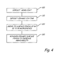
FIG. 4 illustrates a process to prepare a roughened ceramic surface. -
FIG. 1 is a cross-sectional view ofgas turbine engine 10, in a turbofan embodiment. As shown inFIG. 1 ,turbine engine 10 comprisesfan 12 positioned inbypass duct 14, withbypass duct 14 oriented about a turbine core comprising compressor (compressor section) 16, combustor (or combustors) 18 and turbine (turbine section) 20, arranged in flow series withupstream inlet 22 anddownstream exhaust 24. -
Compressor 16 comprises stages ofcompressor vanes 26 andblades 28 arranged in low pressure compressor (LPC)section 30 and high pressure compressor (HPC)section 32.Turbine 20 comprises stages ofturbine vanes 34 andturbine blades 36 arranged in high pressure turbine (HPT)section 38 and low pressure turbine (LPT)section 40. HPTsection 38 is coupled toHPC section 32 viaHPT shaft 42, forming the high pressure spool or high spool.LPT section 40 is coupled toLPC section 30 andfan 12 viaLPT shaft 44, forming the low pressure spool or low spool.HPT shaft 42 andLPT shaft 44 are typically coaxially mounted, with the high and low spools independently rotating about turbine axis (centerline) CL. -
Fan 12 comprises a number of fan airfoils circumferentially arranged around a fan disk or other rotating member, which is coupled (directly or indirectly) toLPC section 30 and driven byLPT shaft 44. In some embodiments,fan 12 is coupled to the fan spool via gearedfan drive mechanism 46, providing independent fan speed control. - As shown in
FIG. 1 ,fan 12 is forward-mounted and provides thrust by accelerating flow downstream throughbypass duct 14, for example in a high-bypass configuration suitable for commercial and regional jet aircraft operations. Alternatively,fan 12 is an unducted fan or propeller assembly, in either a forward or aft-mounted configuration. In these variousembodiments turbine engine 10 comprises any of a high-bypass turbofan, a low-bypass turbofan or a turboprop engine, and the number of spools and the shaft configurations may vary. - In operation of
turbine engine 10, incoming airflow F1 entersinlet 22 and divides into core flow FC and bypass flow FB, downstream offan 12, core flow FC propagates along the core flowpath throughcompressor section 16,combustor 18 andturbine section 20, and bypass flow FB propagates along the bypass flowpath throughbypass duct 14. -
LPC section 30 andHPC section 32 ofcompressor 16 are utilized to compress incoming air forcombustor 18, where fuel is introduced, mixed with air and ignited to produce hot combustion gas. Depending on embodiment,fan 12 also provides some degree of compression (or pre-compression) to core flow FC, andLPC section 30 may be omitted. Alternatively, an additional intermediate spool is included, for example in a three-spool turboprop or turbofan configuration. - Combustion
gas exits combustor 18 and enters HPTsection 38 ofturbine 20, encounteringturbine vanes 34 andturbine blades 36. Turbine vanes 34 turn and accelerate the flow, andturbine blades 36 generate lift for conversion to rotational energy viaHPT shaft 42, driving HPTsection 32 ofcompressor 16 via HPTshaft 42. Partially expanded combustion gas transitions from HPTsection 38 toLPT section 40, drivingLPC section 30 andfan 12 viaLPT shaft 44. Exhaust flowexits LPT section 40 andturbine engine 10 viaexhaust nozzle 24. - The thermodynamic efficiency of
turbine engine 10 is tied to the overall pressure ratio, as defined between the delivery pressure atinlet 22 and the compressed airpressure entering combustor 18 fromcompressor 16. In general, a higher pressure ratio offers increased efficiency and improved performance, including greater specific thrust. High pressure ratios also result in increased peak gas path temperatures, higher core pressure and greater flow rates, increasing thermal and mechanical stress on engine components. - The present invention is intended to be used with stator vanes in turbine engines.
FIG. 2 and FIG. 3 below disclose the invention with respect to a stator vane. The coating of this invention may be used with a rotor shaft. The coating is applied by the process described in commonly owned Patent Application "Thermal Spray Coating Process for Compressor Shafts" (USPN 12/941994 -
FIG. 2 is a cross section along line 2-2 ofFIG. 1 of acasing 48 which has arotor shaft 50 inside.Vanes 26 are attached tocasing 48 and thegas path 52 is shown as the space betweenvanes 26. Coating 60, corresponding to the coating of this invention, is onrotor shaft 50 such that the clearance C betweencoating 60 and thetips 26T ofvanes 26 has the proper tolerance for operation of the engine, e.g., to serve as a seal to prevent leakage of air (thus reducing efficiency), while not interfering with relative movement of the vanes and rotor shaft. -
FIG. 3 shows the cross section along line 3-3 ofFIG. 2 , withcasing 48 andvane 26.Coating 60 is attached torotor 50, with a clearance C betweencoating 60 andvane tip 26T ofvane 26 that varies with operating conditions, as described herein. -
FIG. 3 shows bi-layercoating 60 in detail.Coating 60 comprises a firstmetallic bond coat 62 that has been applied torotor 50.Ceramic coating 64 is placed on top ofmetallic bond coat 62.Ceramic coating 64 has roughened surface 65 that is the subject of this invention. Roughened surface 65 hasasperities 66 that aid in abradingvane surface 26T in clearance C in the event of a physical encounter during engine operation. By acting as an abrading surface, the physical integrity ofceramic layer 64 is maintained at the expense ofabradable vain tip 26T, thereby preserving the insulative and other protective properties ofceramic layer 64 onrotor 50. -
Bond coat 62 is a nickel aluminum alloy or may be formed of MCrAl or MCrAlY where the metal M can be nickel (Ni), iron (Fe), or cobalt (Co), or combinations thereof, and the alloying elements are chromium (Cr), aluminum (Al), and yttrium (Y). For example,bond coat 62 may be 15-40 wt. % Cr, 6-15 wt. % Al, and 0.6-1.0 wt. % Y and the balance is cobalt, nickel, or iron, and combinations thereof. -
Bond coat 62 is thin, up to ten mils (0.25 microns), more specifically ranging from about 3 mils to about 7 mils (about 76 to about 178 microns). In the illustrated embodiment,ceramic coating 62 is about twice as thick, ranging from about 7 mils to about 12 mils (about 178 to about 305 microns). - Roughened
ceramic layer 64 may be any of the zirconia based ceramics such as yttria stabilized zirconia and others as are described in commonly ownedUS Patent Nos. 4,861,618 ,6,102,656 ,6,358,002 , and6,190,124 . A preferred embodiment is a zirconium oxide abrasive coating as described inU.S. Patent 6,190,124 containing 11 to 14 wt. % zirconia with vertical microcracks for mechanical integrity during thermal cycling. Preferably the coating contains 12 wt. % zirconium. - Prior art sealing systems contain an abrading (cutting) surface operating against an abradable surface. Material removed from the abradable surface by the cutter assists in rounding up the surfaces and preventing heating caused by rub interactions between the two surfaces. There are two advantages of using zirconia as an abrading surface. First, vertically microcracked zirconia is extremely hard and can be used against bare superalloy vanes. Since an additional abradable layer in the seal system is not required, repair during engine service is simplified. Secondly, zirconia is a thermal insulator that protects against substrate heating during rub events. Other ceramic coatings such as alumina and cubic boron nitride may also be used.
- The preparation of a ceramic abrading layer is shown in
FIG. 4 . The first step is to deposit a bond coat (Step 100). The metallic bond coat can be deposited by any method known in the art for depositing such materials. For example, the bond coat may be deposited by low pressure plasma spray (LPPS), air plasma spray (APS), electron beam physical vapor deposition (EBPVD), electroplating, cathodic arc or any other method. A preferred embodiment is air plasma spray. The thickness of the bond coat is 0 to 15 mils (381 microns). - The next step is to deposit the ceramic coating (Step 110). The ceramic coating may be deposited by any method known in the art such as LPPS, APS, EBPVD, high velocity oxygen fuel (HVOF) or others known in the art. For zirconia based coatings, thermal spray methods such as air plasma spray or HVOF are preferred to form dense coatings with vertical microcracks. The thickness of the zirconia coating is 3 mils to 25 mils (176 microns to 635 microns). Preferably the thickness of the zirconia coating is 19 mils to 21 mils (483 microns to 533 microns).
- Following deposition, the coated surfaces are ground to a surface finish of about 20 Ra to 30 Ra in microinches (0.51 Ra to 0.76 Ra in microns). (Step 120) In this condition, the smoothness of the ceramic surface is insufficient to remove metal from a blade or vane tip during a high rub interaction event and localized heating, spalling, or other damage is possible.
- The invention is defined in
Step 130 in which the ground ceramic wear surface is roughened to increase abradability such that upon contact the bare vane surfaces will abrade in deference to the roughened ceramic surface. Two embodiments that may be used to roughen the ceramic seal surface are crush grinding and grit blasting. In both cases, the rough surface is produced by locally fracturing the surface to remove particles on the order of the splat size of the thermally deposited ceramic surface typically ranging in size from 0.2 to 1.8 mils (5 to 45 microns). Roughness of the surface is 100 to 300 Ra in microinches (2.54 to 7.62 in microns). Preferably a surface roughness of 150 to 250 Ra in microinches (3.81 to 6.35 in microns) is desired. - Crush grinding is a process normally used to dress grinding wheels to reshape and true the surface profile of the wheel. In this process, another grinding wheel is pushed against the wheel to be trued with considerable force. Both wheels are rotating such that their surfaces are moving in the same direction at their point of contact. The crush grinding wheel can be powered or can be free wheeling. The crushing contact causes individual grits of the working wheel to be removed such that the surface is made to conform to the contour of the crush wheel. The crush wheel can be another grinding wheel or a smooth metal wheel.
- In the context of this invention, the crush grinding wheel is preferably a brazed, fixed diamond grit wheel of about 60 mesh grit size. In the crush grinding process, the crush wheel and the ground ceramic surface of the part are moving in the same direction at their point of contact with about a 20% surface speed differential. The contact force between the two surfaces is about 100 pounds (45.4 kilograms). The resulting interaction results in the fracture and removal of small pieces of the ceramic coating that are on the order of the size of the cooling splats of the thermally deposited ceramic coating. The resulting surface has increased abradability due to the surface roughness. The crush grinding process has been found to produce a repeatable surface texture with good dimensional control.
- Another method to roughen the ground ceramic surface is by grit blasting. In grit blasting, abrasive grit particles are propelled toward the ceramic surface in order to remove pieces from the surface by fracture. Upon impact, the grit particles inject shock waves into the ceramic that result in spallation of ceramic particles on the order of the size of the cooling splats in the thermally deposited coating. In this embodiment, 60 mesh (250 micron) aluminum oxide grit is used with a 0.375 inch (1 centimeter) nozzle running at a 60 psi (0.41 MPa) air pressure. For grit blasting, the part is placed on a turntable of an automated grit blast machine with the nozzle aimed perpendicular to the part surface. The nozzle traverses axially back and forth over the part at a rate of 5 inches (12.7 centimeters) per minute while the part rotates at 20 rpm. The process is typically finished after four complete passes over the surface.
- The present invention successfully provides passive protection against catastrophic thermal runaway events that may cause bum through of the rotor shaft. The invention prevents this by introducing an abrasive surface on a dense thermally insulative coating on a rotor surface that maintains physical integrity in the event of physical contact with vanes. By roughening the ceramic surface, the vane wear mechanism is abrasive metal removal. The wear mechanism with smooth ceramic surfaces is sliding contact adhesive wear and resulting frictional heating and potential failure by bum through.
- While the invention has been described with reference to an exemplary embodiment(s), it will be understood by those skilled in the art that various changes may be made and equivalents may be substituted for elements thereof without departing from the scope of the invention defined by the claims. In addition, many modifications may be made to adapt a particular situation or material to the teachings of the invention without departing from the essential scope thereof. Therefore, it is intended that the invention not be limited to the particular embodiment(s) disclosed, but that the invention will include all embodiments falling within the scope of the appended claims.
Claims (15)
- A method of conditioning a dense ceramic coating (60) to form an abrasive seal comprising:providing a part with a surface;depositing (100) a bond coat (62) on the surface;depositing (110) a ceramic layer (64) on the bond coat;grinding (120) the ceramic surface to a surface finish of 20 to 30 microinches (0.51 microns to 0.76 microns); androughening (130) the ceramic surface to form an abrasive seal.
- The method of claim 1 wherein the bond coat (62) is MCrAlY where M is Ni or Co or alloys thereof.
- The method of claim 1 or 2 wherein the bond coat (62) is deposited by air plasma spraying.
- The method of claim 1, 2 or 3 wherein the ceramic layer (64) is zirconia containing yttria.
- The method of claim 4 wherein the yttria stabilized zirconia contains 11-14 wt. % yttria.
- The method of any preceding claim wherein the ceramic surface (64) is roughened by crush grinding.
- The method of any one of claims 1 to 5 wherein the ceramic surface (64) is roughened by grit blasting.
- An abrasive coating (60) on a rotor (50) that moves relative to cantilevered vanes (26), the coating comprising:a metal bond coat layer (62) on the rotor shaft;a ceramic layer (64) on the metal bond coat layer providing thermal insulation of the rotor; anda roughened surface on the ceramic layer for abrading bare vane tips (26T) that contact the rotor during operation.
- The abrasive coating of claim 8 wherein the metal bond layer (62) ranges in thickness between about 3 mils (76 microns) to about 7 mils (178 microns).
- The abrasive coating of claim 8 or 9 wherein the metal bond layer (62) is formed of a nickel aluminum alloy, MCrAl, or MCrAlY wherein M is nickel, iron, cobalt, or alloys thereof.
- The abrasive coating of claim 10 wherein the metal bond layer (62) is formed of 15-40 wt % Cr, 6-15 wt % Al, 0.6-1.0 wt % Y and the balance nickel, iron, cobalt, or combinations thereof.
- The abrasive coating of any one of claims 8 to 11 wherein the ceramic layer (64) is yttria stabilized zirconia containing 11-14 wt. % yttria, and wherein the ceramic layer (64) is preferably zirconia containing 12 weight percent yttria.
- The abrasive coating of any one of claims 8 to 12 wherein the ceramic layer (64) ranges in thickness between about 3 mils (76 microns) and 25 mils (635 microns).
- The abrasive coating of any one of claims 8 to 13 wherein the roughness of the surface is from about 100 Ra to about 300 Ra in microinches (2540 Ra to 7620 Ra in microns).
- A compressor for a gas turbine engine comprising:a rotor (50) having a plurality of blades extending radially outward from the rotor;a plurality of cantilevered vanes (26) between the rotor blades and extending radially inward toward the rotor; andthe coating (60) of any one of claims 8 to 14 on the portion of the rotor facing bare vane tips of the vanes.
Applications Claiming Priority (1)
| Application Number | Priority Date | Filing Date | Title |
|---|---|---|---|
| US12/910,973 US8770926B2 (en) | 2010-10-25 | 2010-10-25 | Rough dense ceramic sealing surface in turbomachines |
Publications (3)
| Publication Number | Publication Date |
|---|---|
| EP2444515A2 true EP2444515A2 (en) | 2012-04-25 |
| EP2444515A3 EP2444515A3 (en) | 2012-08-08 |
| EP2444515B1 EP2444515B1 (en) | 2013-09-18 |
Family
ID=45560627
Family Applications (1)
| Application Number | Title | Priority Date | Filing Date |
|---|---|---|---|
| EP11186590.3A Active EP2444515B1 (en) | 2010-10-25 | 2011-10-25 | Rough dense ceramic sealing surface in turbomachines |
Country Status (2)
| Country | Link |
|---|---|
| US (1) | US8770926B2 (en) |
| EP (1) | EP2444515B1 (en) |
Cited By (9)
| Publication number | Priority date | Publication date | Assignee | Title |
|---|---|---|---|---|
| WO2014083069A1 (en) * | 2012-11-28 | 2014-06-05 | Nuovo Pignone Srl | Seal systems for use in turbomachines and methods of fabricating the same |
| WO2015130536A1 (en) * | 2014-02-25 | 2015-09-03 | Siemens Energy, Inc. | Turbine abradable layer with progressive wear zone multi depth grooves |
| WO2015173312A1 (en) * | 2014-05-15 | 2015-11-19 | Nuovo Pignone Srl | Method of manufacturing a component of a turbomachine, component of a turbomachine and turbomachine |
| EP3054106A1 (en) * | 2015-02-05 | 2016-08-10 | MTU Aero Engines GmbH | Gas turbine component |
| ITUB20155442A1 (en) * | 2015-11-11 | 2017-05-11 | Ge Avio Srl | STADIUM OF A GAS TURBINE ENGINE PROVIDED WITH A LABYRINTH ESTATE |
| EP3421731A1 (en) * | 2017-06-26 | 2019-01-02 | United Technologies Corporation | Compressor inner air seal and method of making |
| EP3440318A4 (en) * | 2016-04-08 | 2019-11-13 | United Technologies Corporation | Seal geometries for reduced leakage in gas turbines and methods of forming |
| EP2971243B1 (en) | 2013-03-13 | 2020-02-26 | General Electric Company | Coatings for metallic substrates |
| US10760443B2 (en) | 2013-10-02 | 2020-09-01 | Raytheon Technologies Corporation | Turbine abradable air seal system |
Families Citing this family (18)
| Publication number | Priority date | Publication date | Assignee | Title |
|---|---|---|---|---|
| US20110306275A1 (en) * | 2010-06-13 | 2011-12-15 | Nicolson Matthew D | Component finishing tool |
| US20120100299A1 (en) * | 2010-10-25 | 2012-04-26 | United Technologies Corporation | Thermal spray coating process for compressor shafts |
| EP2971547B1 (en) * | 2013-03-12 | 2020-01-01 | United Technologies Corporation | Cantilever stator with vortex initiation feature |
| US9243511B2 (en) * | 2014-02-25 | 2016-01-26 | Siemens Aktiengesellschaft | Turbine abradable layer with zig zag groove pattern |
| US9151175B2 (en) | 2014-02-25 | 2015-10-06 | Siemens Aktiengesellschaft | Turbine abradable layer with progressive wear zone multi level ridge arrays |
| US8939707B1 (en) * | 2014-02-25 | 2015-01-27 | Siemens Energy, Inc. | Turbine abradable layer with progressive wear zone terraced ridges |
| WO2015130521A2 (en) | 2014-02-25 | 2015-09-03 | Siemens Aktiengesellschaft | Turbine component cooling hole within a microsurface feature that protects adjoining thermal barrier coating |
| US8939706B1 (en) * | 2014-02-25 | 2015-01-27 | Siemens Energy, Inc. | Turbine abradable layer with progressive wear zone having a frangible or pixelated nib surface |
| KR20160065226A (en) * | 2014-11-07 | 2016-06-09 | 세메스 주식회사 | Apparatus and method for treating a subtrate |
| WO2016133583A1 (en) | 2015-02-18 | 2016-08-25 | Siemens Aktiengesellschaft | Turbine shroud with abradable layer having ridges with holes |
| EP3259452A2 (en) | 2015-02-18 | 2017-12-27 | Siemens Aktiengesellschaft | Forming cooling passages in combustion turbine superalloy castings |
| US11085116B2 (en) * | 2017-03-22 | 2021-08-10 | The Boeing Company | Engine shaft assembly and method |
| US11028721B2 (en) | 2018-07-19 | 2021-06-08 | Ratheon Technologies Corporation | Coating to improve oxidation and corrosion resistance of abrasive tip system |
| US10927685B2 (en) * | 2018-07-19 | 2021-02-23 | Raytheon Technologies Corporation | Coating to improve oxidation and corrosion resistance of abrasive tip system |
| US11073028B2 (en) | 2018-07-19 | 2021-07-27 | Raytheon Technologies Corporation | Turbine abrasive blade tips with improved resistance to oxidation |
| US11536151B2 (en) | 2020-04-24 | 2022-12-27 | Raytheon Technologies Corporation | Process and material configuration for making hot corrosion resistant HPC abrasive blade tips |
| US11692490B2 (en) * | 2021-05-26 | 2023-07-04 | Doosan Heavy Industries & Construction Co., Ltd. | Gas turbine inner shroud with abradable surface feature |
| US11674448B2 (en) * | 2021-07-16 | 2023-06-13 | Raytheon Technologies Corporation | Seal system having silicon layer and barrier layer |
Citations (4)
| Publication number | Priority date | Publication date | Assignee | Title |
|---|---|---|---|---|
| US4861618A (en) | 1986-10-30 | 1989-08-29 | United Technologies Corporation | Thermal barrier coating system |
| US6102656A (en) | 1995-09-26 | 2000-08-15 | United Technologies Corporation | Segmented abradable ceramic coating |
| US6190124B1 (en) | 1997-11-26 | 2001-02-20 | United Technologies Corporation | Columnar zirconium oxide abrasive coating for a gas turbine engine seal system |
| US6358002B1 (en) | 1998-06-18 | 2002-03-19 | United Technologies Corporation | Article having durable ceramic coating with localized abradable portion |
Family Cites Families (37)
| Publication number | Priority date | Publication date | Assignee | Title |
|---|---|---|---|---|
| US4238170A (en) | 1978-06-26 | 1980-12-09 | United Technologies Corporation | Blade tip seal for an axial flow rotary machine |
| US4227703A (en) | 1978-11-27 | 1980-10-14 | General Electric Company | Gas seal with tip of abrasive particles |
| US4588607A (en) | 1984-11-28 | 1986-05-13 | United Technologies Corporation | Method of applying continuously graded metallic-ceramic layer on metallic substrates |
| US4783341A (en) | 1987-05-04 | 1988-11-08 | United Technologies Corporation | Method and apparatus for measuring the density and hardness of porous plasma sprayed coatings |
| US4884820A (en) | 1987-05-19 | 1989-12-05 | Union Carbide Corporation | Wear resistant, abrasive laser-engraved ceramic or metallic carbide surfaces for rotary labyrinth seal members |
| US4936745A (en) | 1988-12-16 | 1990-06-26 | United Technologies Corporation | Thin abradable ceramic air seal |
| US5536022A (en) | 1990-08-24 | 1996-07-16 | United Technologies Corporation | Plasma sprayed abradable seals for gas turbine engines |
| US5113582A (en) | 1990-11-13 | 1992-05-19 | General Electric Company | Method for making a gas turbine engine component |
| US5196471A (en) | 1990-11-19 | 1993-03-23 | Sulzer Plasma Technik, Inc. | Thermal spray powders for abradable coatings, abradable coatings containing solid lubricants and methods of fabricating abradable coatings |
| US5286541A (en) * | 1992-09-10 | 1994-02-15 | Norton Company | Coated abrasive having combination backing member |
| US5578095A (en) * | 1994-11-21 | 1996-11-26 | Minnesota Mining And Manufacturing Company | Coated abrasive article |
| US5562404A (en) | 1994-12-23 | 1996-10-08 | United Technologies Corporation | Vaned passage hub treatment for cantilever stator vanes |
| US5645399A (en) | 1995-03-15 | 1997-07-08 | United Technologies Corporation | Gas turbine engine case coated with thermal barrier coating to control axial airfoil clearance |
| US5639211A (en) | 1995-11-30 | 1997-06-17 | United Technology Corporation | Brush seal for stator of a gas turbine engine case |
| US6120640A (en) * | 1996-12-19 | 2000-09-19 | Applied Materials, Inc. | Boron carbide parts and coatings in a plasma reactor |
| US5952110A (en) | 1996-12-24 | 1999-09-14 | General Electric Company | Abrasive ceramic matrix turbine blade tip and method for forming |
| DE19730008C1 (en) | 1997-07-12 | 1998-10-29 | Mtu Muenchen Gmbh | Sheathing for metallic engine component |
| US5879753A (en) | 1997-12-19 | 1999-03-09 | United Technologies Corporation | Thermal spray coating process for rotor blade tips using a rotatable holding fixture |
| US6089825A (en) | 1998-12-18 | 2000-07-18 | United Technologies Corporation | Abradable seal having improved properties and method of producing seal |
| US6383658B1 (en) | 1999-11-18 | 2002-05-07 | General Electric Company | Thermally sprayed coatings having an interface with controlled cleanliness |
| US6537021B2 (en) | 2001-06-06 | 2003-03-25 | Chromalloy Gas Turbine Corporation | Abradeable seal system |
| US6703137B2 (en) | 2001-08-02 | 2004-03-09 | Siemens Westinghouse Power Corporation | Segmented thermal barrier coating and method of manufacturing the same |
| US8357454B2 (en) | 2001-08-02 | 2013-01-22 | Siemens Energy, Inc. | Segmented thermal barrier coating |
| US20040005452A1 (en) | 2002-01-14 | 2004-01-08 | Dorfman Mitchell R. | High temperature spray dried composite abradable powder for combustion spraying and abradable barrier coating produced using same |
| GB0400752D0 (en) * | 2004-01-13 | 2004-02-18 | Rolls Royce Plc | Cantilevered stator stage |
| US8033094B2 (en) | 2004-12-01 | 2011-10-11 | United Technologies Corporation | Cantilevered tip turbine engine |
| US7407369B2 (en) | 2004-12-29 | 2008-08-05 | United Technologies Corporation | Gas turbine engine blade tip clearance apparatus and method |
| US7510370B2 (en) | 2005-02-01 | 2009-03-31 | Honeywell International Inc. | Turbine blade tip and shroud clearance control coating system |
| US20070274837A1 (en) * | 2006-05-26 | 2007-11-29 | Thomas Alan Taylor | Blade tip coatings |
| US7726937B2 (en) | 2006-09-12 | 2010-06-01 | United Technologies Corporation | Turbine engine compressor vanes |
| US20100098923A1 (en) | 2006-10-05 | 2010-04-22 | United Technologies Corporation | Segmented abradable coatings and process (ES) for applying the same |
| US8038388B2 (en) | 2007-03-05 | 2011-10-18 | United Technologies Corporation | Abradable component for a gas turbine engine |
| US7892652B2 (en) | 2007-03-13 | 2011-02-22 | United Technologies Corporation | Low stress metallic based coating |
| US8061978B2 (en) | 2007-10-16 | 2011-11-22 | United Technologies Corp. | Systems and methods involving abradable air seals |
| US7998604B2 (en) * | 2007-11-28 | 2011-08-16 | United Technologies Corporation | Article having composite layer |
| GB0822416D0 (en) | 2008-12-10 | 2009-01-14 | Rolls Royce Plc | A seal and a method of manufacturing a seal |
| US8246477B2 (en) * | 2010-05-20 | 2012-08-21 | Moyno, Inc. | Gear joint with super finished surfaces |
-
2010
- 2010-10-25 US US12/910,973 patent/US8770926B2/en active Active
-
2011
- 2011-10-25 EP EP11186590.3A patent/EP2444515B1/en active Active
Patent Citations (4)
| Publication number | Priority date | Publication date | Assignee | Title |
|---|---|---|---|---|
| US4861618A (en) | 1986-10-30 | 1989-08-29 | United Technologies Corporation | Thermal barrier coating system |
| US6102656A (en) | 1995-09-26 | 2000-08-15 | United Technologies Corporation | Segmented abradable ceramic coating |
| US6190124B1 (en) | 1997-11-26 | 2001-02-20 | United Technologies Corporation | Columnar zirconium oxide abrasive coating for a gas turbine engine seal system |
| US6358002B1 (en) | 1998-06-18 | 2002-03-19 | United Technologies Corporation | Article having durable ceramic coating with localized abradable portion |
Cited By (15)
| Publication number | Priority date | Publication date | Assignee | Title |
|---|---|---|---|---|
| JP2016508202A (en) * | 2012-11-28 | 2016-03-17 | ヌオーヴォ ピニォーネ ソチエタ レスポンサビリタ リミタータNuovo Pignone S.R.L. | Seal system for use in a turbomachine and method of making the same |
| US9598973B2 (en) | 2012-11-28 | 2017-03-21 | General Electric Company | Seal systems for use in turbomachines and methods of fabricating the same |
| WO2014083069A1 (en) * | 2012-11-28 | 2014-06-05 | Nuovo Pignone Srl | Seal systems for use in turbomachines and methods of fabricating the same |
| EP2971243B1 (en) | 2013-03-13 | 2020-02-26 | General Electric Company | Coatings for metallic substrates |
| US10760443B2 (en) | 2013-10-02 | 2020-09-01 | Raytheon Technologies Corporation | Turbine abradable air seal system |
| WO2015130536A1 (en) * | 2014-02-25 | 2015-09-03 | Siemens Energy, Inc. | Turbine abradable layer with progressive wear zone multi depth grooves |
| WO2015173312A1 (en) * | 2014-05-15 | 2015-11-19 | Nuovo Pignone Srl | Method of manufacturing a component of a turbomachine, component of a turbomachine and turbomachine |
| US11105216B2 (en) | 2014-05-15 | 2021-08-31 | Nuovo Pignone Srl | Method of manufacturing a component of a turbomachine, component of a turbomachine and turbomachine |
| EP3054106A1 (en) * | 2015-02-05 | 2016-08-10 | MTU Aero Engines GmbH | Gas turbine component |
| US11248484B2 (en) | 2015-02-05 | 2022-02-15 | MTU Aero Engines AG | Gas turbine component |
| ITUB20155442A1 (en) * | 2015-11-11 | 2017-05-11 | Ge Avio Srl | STADIUM OF A GAS TURBINE ENGINE PROVIDED WITH A LABYRINTH ESTATE |
| EP3168427A1 (en) * | 2015-11-11 | 2017-05-17 | Ge Avio S.r.l. | Gas turbine engine stage provided with a labyrinth seal |
| EP3440318A4 (en) * | 2016-04-08 | 2019-11-13 | United Technologies Corporation | Seal geometries for reduced leakage in gas turbines and methods of forming |
| US10794211B2 (en) | 2016-04-08 | 2020-10-06 | Raytheon Technologies Corporation | Seal geometries for reduced leakage in gas turbines and methods of forming |
| EP3421731A1 (en) * | 2017-06-26 | 2019-01-02 | United Technologies Corporation | Compressor inner air seal and method of making |
Also Published As
| Publication number | Publication date |
|---|---|
| EP2444515B1 (en) | 2013-09-18 |
| US20120099972A1 (en) | 2012-04-26 |
| EP2444515A3 (en) | 2012-08-08 |
| US8770926B2 (en) | 2014-07-08 |
Similar Documents
| Publication | Publication Date | Title |
|---|---|---|
| EP2444515B1 (en) | Rough dense ceramic sealing surface in turbomachines | |
| EP2444513B1 (en) | Abrasive rotor shaft ceramic coating | |
| US8936432B2 (en) | Low density abradable coating with fine porosity | |
| EP2444516A1 (en) | Thermal spray coating process for compressor shafts | |
| EP2444593B1 (en) | Friable ceramic rotor shaft abrasive coating | |
| EP2455589B1 (en) | Abrasive cutter formed by thermal spray and post treatment | |
| EP3440318B1 (en) | Seal geometries for reduced leakage in gas turbines and methods of forming | |
| US20120189434A1 (en) | Coating with abradability proportional to interaction rate | |
| EP3480428B1 (en) | Abrasive airfoil tip and fabrication method thereof | |
| US20120099971A1 (en) | Self dressing, mildly abrasive coating for clearance control | |
| EP3061850B1 (en) | Hard phaseless metallic coating for compressor blade tip | |
| EP2428593B1 (en) | Abradable coating with safety fuse | |
| EP3020931B1 (en) | Abrasive rotor coating with rub force limiting features | |
| EP2540868B1 (en) | Spall resistant abradable turbine air seal | |
| EP3318719B1 (en) | Turbomachine rotor with coated blades | |
| US20180087387A1 (en) | Compositions and methods for coating metal turbine blade tips | |
| EP2453110A1 (en) | Method of forming a seal in a gas turbine engine, corresponding blade airfoil and seal combination and gas turbine engine | |
| US20180135638A1 (en) | Ceramic coating composition for compressor casing and methods for forming the same |
Legal Events
| Date | Code | Title | Description |
|---|---|---|---|
| AK | Designated contracting states |
Kind code of ref document: A2 Designated state(s): AL AT BE BG CH CY CZ DE DK EE ES FI FR GB GR HR HU IE IS IT LI LT LU LV MC MK MT NL NO PL PT RO RS SE SI SK SM TR |
|
| AX | Request for extension of the european patent |
Extension state: BA ME |
|
| PUAI | Public reference made under article 153(3) epc to a published international application that has entered the european phase |
Free format text: ORIGINAL CODE: 0009012 |
|
| PUAL | Search report despatched |
Free format text: ORIGINAL CODE: 0009013 |
|
| AK | Designated contracting states |
Kind code of ref document: A3 Designated state(s): AL AT BE BG CH CY CZ DE DK EE ES FI FR GB GR HR HU IE IS IT LI LT LU LV MC MK MT NL NO PL PT RO RS SE SI SK SM TR |
|
| AX | Request for extension of the european patent |
Extension state: BA ME |
|
| RIC1 | Information provided on ipc code assigned before grant |
Ipc: F01D 11/00 20060101ALI20120702BHEP Ipc: C23C 4/10 20060101ALI20120702BHEP Ipc: C23C 4/18 20060101ALI20120702BHEP Ipc: F01D 5/28 20060101ALI20120702BHEP Ipc: C23C 4/08 20060101AFI20120702BHEP Ipc: F01D 11/12 20060101ALI20120702BHEP Ipc: F01D 11/08 20060101ALI20120702BHEP Ipc: C23C 30/00 20060101ALI20120702BHEP |
|
| 17P | Request for examination filed |
Effective date: 20130208 |
|
| RIC1 | Information provided on ipc code assigned before grant |
Ipc: C23C 4/10 20060101ALI20130228BHEP Ipc: F01D 11/12 20060101ALI20130228BHEP Ipc: C23C 30/00 20060101ALI20130228BHEP Ipc: C23C 4/18 20060101ALI20130228BHEP Ipc: F01D 11/08 20060101ALI20130228BHEP Ipc: F01D 5/28 20060101ALI20130228BHEP Ipc: F01D 11/00 20060101ALI20130228BHEP Ipc: C23C 4/08 20060101AFI20130228BHEP |
|
| GRAP | Despatch of communication of intention to grant a patent |
Free format text: ORIGINAL CODE: EPIDOSNIGR1 |
|
| INTG | Intention to grant announced |
Effective date: 20130417 |
|
| GRAS | Grant fee paid |
Free format text: ORIGINAL CODE: EPIDOSNIGR3 |
|
| GRAA | (expected) grant |
Free format text: ORIGINAL CODE: 0009210 |
|
| AK | Designated contracting states |
Kind code of ref document: B1 Designated state(s): AL AT BE BG CH CY CZ DE DK EE ES FI FR GB GR HR HU IE IS IT LI LT LU LV MC MK MT NL NO PL PT RO RS SE SI SK SM TR |
|
| REG | Reference to a national code |
Ref country code: GB Ref legal event code: FG4D |
|
| REG | Reference to a national code |
Ref country code: CH Ref legal event code: EP |
|
| REG | Reference to a national code |
Ref country code: IE Ref legal event code: FG4D |
|
| REG | Reference to a national code |
Ref country code: AT Ref legal event code: REF Ref document number: 632861 Country of ref document: AT Kind code of ref document: T Effective date: 20131015 |
|
| REG | Reference to a national code |
Ref country code: DE Ref legal event code: R096 Ref document number: 602011003114 Country of ref document: DE Effective date: 20131114 |
|
| PG25 | Lapsed in a contracting state [announced via postgrant information from national office to epo] |
Ref country code: HR Free format text: LAPSE BECAUSE OF FAILURE TO SUBMIT A TRANSLATION OF THE DESCRIPTION OR TO PAY THE FEE WITHIN THE PRESCRIBED TIME-LIMIT Effective date: 20130918 Ref country code: LT Free format text: LAPSE BECAUSE OF FAILURE TO SUBMIT A TRANSLATION OF THE DESCRIPTION OR TO PAY THE FEE WITHIN THE PRESCRIBED TIME-LIMIT Effective date: 20130918 Ref country code: NO Free format text: LAPSE BECAUSE OF FAILURE TO SUBMIT A TRANSLATION OF THE DESCRIPTION OR TO PAY THE FEE WITHIN THE PRESCRIBED TIME-LIMIT Effective date: 20131218 Ref country code: SE Free format text: LAPSE BECAUSE OF FAILURE TO SUBMIT A TRANSLATION OF THE DESCRIPTION OR TO PAY THE FEE WITHIN THE PRESCRIBED TIME-LIMIT Effective date: 20130918 Ref country code: CY Free format text: LAPSE BECAUSE OF FAILURE TO SUBMIT A TRANSLATION OF THE DESCRIPTION OR TO PAY THE FEE WITHIN THE PRESCRIBED TIME-LIMIT Effective date: 20130821 |
|
| REG | Reference to a national code |
Ref country code: NL Ref legal event code: VDEP Effective date: 20130918 |
|
| REG | Reference to a national code |
Ref country code: AT Ref legal event code: MK05 Ref document number: 632861 Country of ref document: AT Kind code of ref document: T Effective date: 20130918 |
|
| REG | Reference to a national code |
Ref country code: LT Ref legal event code: MG4D |
|
| PG25 | Lapsed in a contracting state [announced via postgrant information from national office to epo] |
Ref country code: RS Free format text: LAPSE BECAUSE OF FAILURE TO SUBMIT A TRANSLATION OF THE DESCRIPTION OR TO PAY THE FEE WITHIN THE PRESCRIBED TIME-LIMIT Effective date: 20130918 Ref country code: GR Free format text: LAPSE BECAUSE OF FAILURE TO SUBMIT A TRANSLATION OF THE DESCRIPTION OR TO PAY THE FEE WITHIN THE PRESCRIBED TIME-LIMIT Effective date: 20131219 Ref country code: SI Free format text: LAPSE BECAUSE OF FAILURE TO SUBMIT A TRANSLATION OF THE DESCRIPTION OR TO PAY THE FEE WITHIN THE PRESCRIBED TIME-LIMIT Effective date: 20130918 Ref country code: FI Free format text: LAPSE BECAUSE OF FAILURE TO SUBMIT A TRANSLATION OF THE DESCRIPTION OR TO PAY THE FEE WITHIN THE PRESCRIBED TIME-LIMIT Effective date: 20130918 Ref country code: LV Free format text: LAPSE BECAUSE OF FAILURE TO SUBMIT A TRANSLATION OF THE DESCRIPTION OR TO PAY THE FEE WITHIN THE PRESCRIBED TIME-LIMIT Effective date: 20130918 |
|
| PG25 | Lapsed in a contracting state [announced via postgrant information from national office to epo] |
Ref country code: CY Free format text: LAPSE BECAUSE OF FAILURE TO SUBMIT A TRANSLATION OF THE DESCRIPTION OR TO PAY THE FEE WITHIN THE PRESCRIBED TIME-LIMIT Effective date: 20130918 Ref country code: BE Free format text: LAPSE BECAUSE OF FAILURE TO SUBMIT A TRANSLATION OF THE DESCRIPTION OR TO PAY THE FEE WITHIN THE PRESCRIBED TIME-LIMIT Effective date: 20130918 |
|
| PG25 | Lapsed in a contracting state [announced via postgrant information from national office to epo] |
Ref country code: IS Free format text: LAPSE BECAUSE OF FAILURE TO SUBMIT A TRANSLATION OF THE DESCRIPTION OR TO PAY THE FEE WITHIN THE PRESCRIBED TIME-LIMIT Effective date: 20140118 Ref country code: NL Free format text: LAPSE BECAUSE OF FAILURE TO SUBMIT A TRANSLATION OF THE DESCRIPTION OR TO PAY THE FEE WITHIN THE PRESCRIBED TIME-LIMIT Effective date: 20130918 Ref country code: EE Free format text: LAPSE BECAUSE OF FAILURE TO SUBMIT A TRANSLATION OF THE DESCRIPTION OR TO PAY THE FEE WITHIN THE PRESCRIBED TIME-LIMIT Effective date: 20130918 Ref country code: SK Free format text: LAPSE BECAUSE OF FAILURE TO SUBMIT A TRANSLATION OF THE DESCRIPTION OR TO PAY THE FEE WITHIN THE PRESCRIBED TIME-LIMIT Effective date: 20130918 Ref country code: CZ Free format text: LAPSE BECAUSE OF FAILURE TO SUBMIT A TRANSLATION OF THE DESCRIPTION OR TO PAY THE FEE WITHIN THE PRESCRIBED TIME-LIMIT Effective date: 20130918 |
|
| PG25 | Lapsed in a contracting state [announced via postgrant information from national office to epo] |
Ref country code: PL Free format text: LAPSE BECAUSE OF FAILURE TO SUBMIT A TRANSLATION OF THE DESCRIPTION OR TO PAY THE FEE WITHIN THE PRESCRIBED TIME-LIMIT Effective date: 20130918 Ref country code: ES Free format text: LAPSE BECAUSE OF FAILURE TO SUBMIT A TRANSLATION OF THE DESCRIPTION OR TO PAY THE FEE WITHIN THE PRESCRIBED TIME-LIMIT Effective date: 20130918 Ref country code: AT Free format text: LAPSE BECAUSE OF FAILURE TO SUBMIT A TRANSLATION OF THE DESCRIPTION OR TO PAY THE FEE WITHIN THE PRESCRIBED TIME-LIMIT Effective date: 20130918 |
|
| REG | Reference to a national code |
Ref country code: DE Ref legal event code: R097 Ref document number: 602011003114 Country of ref document: DE |
|
| PG25 | Lapsed in a contracting state [announced via postgrant information from national office to epo] |
Ref country code: PT Free format text: LAPSE BECAUSE OF FAILURE TO SUBMIT A TRANSLATION OF THE DESCRIPTION OR TO PAY THE FEE WITHIN THE PRESCRIBED TIME-LIMIT Effective date: 20140120 Ref country code: MC Free format text: LAPSE BECAUSE OF FAILURE TO SUBMIT A TRANSLATION OF THE DESCRIPTION OR TO PAY THE FEE WITHIN THE PRESCRIBED TIME-LIMIT Effective date: 20130918 |
|
| PLBE | No opposition filed within time limit |
Free format text: ORIGINAL CODE: 0009261 |
|
| STAA | Information on the status of an ep patent application or granted ep patent |
Free format text: STATUS: NO OPPOSITION FILED WITHIN TIME LIMIT |
|
| REG | Reference to a national code |
Ref country code: IE Ref legal event code: MM4A |
|
| REG | Reference to a national code |
Ref country code: FR Ref legal event code: ST Effective date: 20140630 |
|
| 26N | No opposition filed |
Effective date: 20140619 |
|
| PG25 | Lapsed in a contracting state [announced via postgrant information from national office to epo] |
Ref country code: IT Free format text: LAPSE BECAUSE OF FAILURE TO SUBMIT A TRANSLATION OF THE DESCRIPTION OR TO PAY THE FEE WITHIN THE PRESCRIBED TIME-LIMIT Effective date: 20130918 Ref country code: FR Free format text: LAPSE BECAUSE OF NON-PAYMENT OF DUE FEES Effective date: 20131118 |
|
| PG25 | Lapsed in a contracting state [announced via postgrant information from national office to epo] |
Ref country code: DK Free format text: LAPSE BECAUSE OF FAILURE TO SUBMIT A TRANSLATION OF THE DESCRIPTION OR TO PAY THE FEE WITHIN THE PRESCRIBED TIME-LIMIT Effective date: 20130918 |
|
| REG | Reference to a national code |
Ref country code: DE Ref legal event code: R097 Ref document number: 602011003114 Country of ref document: DE Effective date: 20140619 |
|
| PG25 | Lapsed in a contracting state [announced via postgrant information from national office to epo] |
Ref country code: IE Free format text: LAPSE BECAUSE OF NON-PAYMENT OF DUE FEES Effective date: 20131025 |
|
| PG25 | Lapsed in a contracting state [announced via postgrant information from national office to epo] |
Ref country code: RO Free format text: LAPSE BECAUSE OF FAILURE TO SUBMIT A TRANSLATION OF THE DESCRIPTION OR TO PAY THE FEE WITHIN THE PRESCRIBED TIME-LIMIT Effective date: 20130918 |
|
| PG25 | Lapsed in a contracting state [announced via postgrant information from national office to epo] |
Ref country code: SM Free format text: LAPSE BECAUSE OF FAILURE TO SUBMIT A TRANSLATION OF THE DESCRIPTION OR TO PAY THE FEE WITHIN THE PRESCRIBED TIME-LIMIT Effective date: 20130918 |
|
| REG | Reference to a national code |
Ref country code: CH Ref legal event code: PL |
|
| PG25 | Lapsed in a contracting state [announced via postgrant information from national office to epo] |
Ref country code: TR Free format text: LAPSE BECAUSE OF FAILURE TO SUBMIT A TRANSLATION OF THE DESCRIPTION OR TO PAY THE FEE WITHIN THE PRESCRIBED TIME-LIMIT Effective date: 20130918 |
|
| PG25 | Lapsed in a contracting state [announced via postgrant information from national office to epo] |
Ref country code: CH Free format text: LAPSE BECAUSE OF NON-PAYMENT OF DUE FEES Effective date: 20141031 Ref country code: LI Free format text: LAPSE BECAUSE OF NON-PAYMENT OF DUE FEES Effective date: 20141031 Ref country code: BG Free format text: LAPSE BECAUSE OF FAILURE TO SUBMIT A TRANSLATION OF THE DESCRIPTION OR TO PAY THE FEE WITHIN THE PRESCRIBED TIME-LIMIT Effective date: 20130918 Ref country code: MK Free format text: LAPSE BECAUSE OF FAILURE TO SUBMIT A TRANSLATION OF THE DESCRIPTION OR TO PAY THE FEE WITHIN THE PRESCRIBED TIME-LIMIT Effective date: 20130918 Ref country code: LU Free format text: LAPSE BECAUSE OF NON-PAYMENT OF DUE FEES Effective date: 20131025 Ref country code: HU Free format text: LAPSE BECAUSE OF FAILURE TO SUBMIT A TRANSLATION OF THE DESCRIPTION OR TO PAY THE FEE WITHIN THE PRESCRIBED TIME-LIMIT; INVALID AB INITIO Effective date: 20111025 |
|
| PG25 | Lapsed in a contracting state [announced via postgrant information from national office to epo] |
Ref country code: MT Free format text: LAPSE BECAUSE OF FAILURE TO SUBMIT A TRANSLATION OF THE DESCRIPTION OR TO PAY THE FEE WITHIN THE PRESCRIBED TIME-LIMIT Effective date: 20130918 |
|
| REG | Reference to a national code |
Ref country code: DE Ref legal event code: R082 Ref document number: 602011003114 Country of ref document: DE Representative=s name: SCHMITT-NILSON SCHRAUD WAIBEL WOHLFROM PATENTA, DE |
|
| REG | Reference to a national code |
Ref country code: DE Ref legal event code: R082 Ref document number: 602011003114 Country of ref document: DE Representative=s name: SCHMITT-NILSON SCHRAUD WAIBEL WOHLFROM PATENTA, DE Ref country code: DE Ref legal event code: R081 Ref document number: 602011003114 Country of ref document: DE Owner name: UNITED TECHNOLOGIES CORP. (N.D.GES.D. STAATES , US Free format text: FORMER OWNER: UNITED TECHNOLOGIES CORP., HARTFORD, CONN., US |
|
| PG25 | Lapsed in a contracting state [announced via postgrant information from national office to epo] |
Ref country code: AL Free format text: LAPSE BECAUSE OF FAILURE TO SUBMIT A TRANSLATION OF THE DESCRIPTION OR TO PAY THE FEE WITHIN THE PRESCRIBED TIME-LIMIT Effective date: 20130918 |
|
| REG | Reference to a national code |
Ref country code: DE Ref legal event code: R081 Ref document number: 602011003114 Country of ref document: DE Owner name: RAYTHEON TECHNOLOGIES CORPORATION (N.D.GES.D.S, US Free format text: FORMER OWNER: UNITED TECHNOLOGIES CORP. (N.D.GES.D. STAATES DELAWARE), FARMINGTON, CONN., US |
|
| P01 | Opt-out of the competence of the unified patent court (upc) registered |
Effective date: 20230520 |
|
| PGFP | Annual fee paid to national office [announced via postgrant information from national office to epo] |
Ref country code: GB Payment date: 20230920 Year of fee payment: 13 |
|
| PGFP | Annual fee paid to national office [announced via postgrant information from national office to epo] |
Ref country code: DE Payment date: 20230920 Year of fee payment: 13 |