EP2444256A1 - Variable-diameter wheel - Google Patents
Variable-diameter wheel Download PDFInfo
- Publication number
- EP2444256A1 EP2444256A1 EP11185132A EP11185132A EP2444256A1 EP 2444256 A1 EP2444256 A1 EP 2444256A1 EP 11185132 A EP11185132 A EP 11185132A EP 11185132 A EP11185132 A EP 11185132A EP 2444256 A1 EP2444256 A1 EP 2444256A1
- Authority
- EP
- European Patent Office
- Prior art keywords
- wheel
- diameter
- axle
- hub
- variation mechanism
- Prior art date
- Legal status (The legal status is an assumption and is not a legal conclusion. Google has not performed a legal analysis and makes no representation as to the accuracy of the status listed.)
- Granted
Links
- 230000007246 mechanism Effects 0.000 claims abstract description 43
- 239000002360 explosive Substances 0.000 description 2
- 239000000463 material Substances 0.000 description 2
- 238000007789 sealing Methods 0.000 description 2
- 230000009471 action Effects 0.000 description 1
- 230000003213 activating effect Effects 0.000 description 1
- 230000008859 change Effects 0.000 description 1
- 239000003795 chemical substances by application Substances 0.000 description 1
- 230000007423 decrease Effects 0.000 description 1
- 238000006073 displacement reaction Methods 0.000 description 1
- 239000000428 dust Substances 0.000 description 1
- 238000000034 method Methods 0.000 description 1
- 230000008569 process Effects 0.000 description 1
- 230000000630 rising effect Effects 0.000 description 1
- 239000011435 rock Substances 0.000 description 1
- 239000007787 solid Substances 0.000 description 1
- 239000000126 substance Substances 0.000 description 1
- XLYOFNOQVPJJNP-UHFFFAOYSA-N water Substances O XLYOFNOQVPJJNP-UHFFFAOYSA-N 0.000 description 1
Images


Classifications
-
- B—PERFORMING OPERATIONS; TRANSPORTING
- B60—VEHICLES IN GENERAL
- B60B—VEHICLE WHEELS; CASTORS; AXLES FOR WHEELS OR CASTORS; INCREASING WHEEL ADHESION
- B60B15/00—Wheels or wheel attachments designed for increasing traction
- B60B15/02—Wheels with spade lugs
- B60B15/10—Wheels with spade lugs with radially-adjustable spade lugs; Control mechanisms therefor
- B60B15/14—Wheels with spade lugs with radially-adjustable spade lugs; Control mechanisms therefor involving an axially-displaceable cone
-
- B—PERFORMING OPERATIONS; TRANSPORTING
- B60—VEHICLES IN GENERAL
- B60B—VEHICLE WHEELS; CASTORS; AXLES FOR WHEELS OR CASTORS; INCREASING WHEEL ADHESION
- B60B15/00—Wheels or wheel attachments designed for increasing traction
- B60B15/18—Wheels with ground-engaging plate-like shoes
-
- B—PERFORMING OPERATIONS; TRANSPORTING
- B60—VEHICLES IN GENERAL
- B60B—VEHICLE WHEELS; CASTORS; AXLES FOR WHEELS OR CASTORS; INCREASING WHEEL ADHESION
- B60B19/00—Wheels not otherwise provided for or having characteristics specified in one of the subgroups of this group
- B60B19/04—Wheels not otherwise provided for or having characteristics specified in one of the subgroups of this group expansible
-
- F—MECHANICAL ENGINEERING; LIGHTING; HEATING; WEAPONS; BLASTING
- F16—ENGINEERING ELEMENTS AND UNITS; GENERAL MEASURES FOR PRODUCING AND MAINTAINING EFFECTIVE FUNCTIONING OF MACHINES OR INSTALLATIONS; THERMAL INSULATION IN GENERAL
- F16H—GEARING
- F16H55/00—Elements with teeth or friction surfaces for conveying motion; Worms, pulleys or sheaves for gearing mechanisms
- F16H55/32—Friction members
- F16H55/52—Pulleys or friction discs of adjustable construction
- F16H55/54—Pulleys or friction discs of adjustable construction of which the bearing parts are radially adjustable
-
- B—PERFORMING OPERATIONS; TRANSPORTING
- B60—VEHICLES IN GENERAL
- B60B—VEHICLE WHEELS; CASTORS; AXLES FOR WHEELS OR CASTORS; INCREASING WHEEL ADHESION
- B60B2900/00—Purpose of invention
- B60B2900/50—Improvement of
- B60B2900/551—Handling of obstacles or difficult terrains
-
- B—PERFORMING OPERATIONS; TRANSPORTING
- B60—VEHICLES IN GENERAL
- B60Y—INDEXING SCHEME RELATING TO ASPECTS CROSS-CUTTING VEHICLE TECHNOLOGY
- B60Y2200/00—Type of vehicle
- B60Y2200/20—Off-Road Vehicles
-
- B—PERFORMING OPERATIONS; TRANSPORTING
- B60—VEHICLES IN GENERAL
- B60Y—INDEXING SCHEME RELATING TO ASPECTS CROSS-CUTTING VEHICLE TECHNOLOGY
- B60Y2200/00—Type of vehicle
- B60Y2200/20—Off-Road Vehicles
- B60Y2200/24—Military vehicles
Definitions
- the present invention relates to a wheel which comprises a passive mechanism adapted to vary its outer diameter according to the drive torque applied to said wheel.
- the present invention is applicable, in particular, to vehicles or wheel-based mechanisms in general.
- medium and large-diameter wheels such as, for example, those of armoured and/or amphibious vehicles, take up much space when stored and are difficult to handle, e.g. when they must be replaced, thus causing both logistic and operational problems.
- the present invention aims at solving the above-mentioned technical problems by providing a wheel which comprises a mechanism, preferably an automated one, for varying the outer diameter of said wheel, preferably drive wheels of vehicles or of wheel-based mechanisms.
- This mechanism allows such vehicles to overcome obstacles which are higher than the wheel axis when the wheel is in the idle condition.
- Such a mechanism may also be used for varying the diameter of said wheel according to the applied torque.
- One aspect of the present invention relates to a wheel having a variable outer diameter with the features set out in the appended claim 1.
- wheel 1 with a variable outer diameter comprises at least one rim or hub 11 with a predefined diameter, to which at least one drive axle 14 of wheel 1 is connected; at least one surface external to hub 11, having a greater diameter than said hub 11.
- Said wheel 1 comprises at least one diameter variation mechanism 3, secured to said axle 14 and adapted to vary the actual diameter of said wheel 1 according to the torque applied to drive axle 14 by at least one propulsion system.
- Said diameter variation mechanism 3 can take at least two operating configurations:
- substantially incorporated means that there are no parts of the mechanism protruding from the outer diameter of the wheel and affecting the behaviour thereof as it rotates.
- said wheel 1 is applied to a vehicle, and the outer diameter of the outer surface of said wheel 1 is defined by at least one tread 12 of at least one tyre 10 mounted on hub 11.
- the variation of the torque applied to axle 14 of wheel 1 due, for example, to wheel 1 being obstructed or blocked by an obstacle "O" brings the diameter variation mechanism 3 into the active operating configuration.
- Said diameter variation mechanism 3 comprises:
- Rim 11 comprises a hollow structure 110 into which variation mechanism 3 is substantially incorporated.
- Said hollow 110 comprises at least one guide insert 21, which comprises at least one first threaded portion 211 and which is adapted to guide actuation device 33 as mechanism 3 switches between the different operating configurations.
- contact portions 31 are at least partially incorporated within tyre 10, in particular within tread 12.
- Said contact portions 31 have preferably a rectangular shape, and their width is at most equal to the width of tread 12.
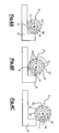
- said contact portions have such an inclination as to generate a step with a following contact portion 31'. Said step can be seen by observing the wheel from the sides, as shown in Figs. 4B and 4C , when mechanism 3 is in the active configuration.
- the number of external portions 31, and therefore of rods 32, must be such that, when viewing the wheel from one side, a pseudocylindrical envelope of contact portions 31 is obtained.
- the number of said external portions 31 is preferably at least 8.
- Each rod 32 slides radially, thus crossing both hub 11 and tyre 10, by exploiting the centrifugal or centripetal action caused by the change of the operating state of diameter-variation mechanism 3.
- hub 11 comprises one aperture 321 for each rod 32.
- each rod 32 is countered by at least one elastic means (not shown), which prevents said rods 32 from sliding during the normal rotation of wheel 1, if the diameter-variation mechanism 3 has not been activated; furthermore, said elastic means is such that it brings sliding rods 32 back to their proper position when mechanism 3 switches to the idle configuration.
- wheel 1 comprises a tubeless solid tyre 10 which comprises a more or less thick layer of tread 12.
- a wheel 1 comprising at least one tube-type or tubeless tyre which is nonetheless suitable for the application concerned.
- the first threaded portion 211 whose thread follows the main direction of rotation of axle 14, can be coupled to a second threaded portion 331, comprised in the actuation device and following the main direction of rotation of axle 14.
- Actuation device 33 is secured, preferably by keying, to axle 14.
- Threaded portion 331 of actuation device 33 is substantially cylindrical, with a diameter equal to that of hollow structure 110 that comprises guide insert 21.
- Actuation element 33 also comprises at least one tapered portion 332.
- Said tapered portion 332 is preferably smooth and has, for example, a linear and constant inclination.
- Said tapered portion 332 is acted upon by kinematic device 22, which is preferably a small-diameter wheel appropriately connected to sliding rod 32, e.g. through a fork.
- Said kinematic device 22 is preferably directly in contact with actuation device 33.
- the actuation device substantially has the shape of a truncated cone, with the major base secured to shaft 14 and the minor base facing the inside of hollow structure 110.
- such a motion of device 33 allows kinematic device 22 to move along the inclined plane of tapered portion 332, thus allowing rods 32 to slide radially and contact portions 31 to be raised or lowered with respect to the profile of tread 12.
- the movement of the above-mentioned parts depends on the direction of axial movement of actuation device 3 and on the thread direction of the threaded portions (331 and 211).
- the rising of contact portions 31 corresponds to a forward movement of actuation device 33 inside hollow portion 110, whose thread follows the main direction of rotation of drive axle 14 of wheel 1.
- the actuation of mechanism 3 is controlled by the control element, which consists of an elastic element, preferably a coil spring 341, arranged between a fixing portion 333, comprised in the actuation device, and a thrust insert 13, comprised in rim 11 and delimiting hollow portion 110 on one side.
- the control element which consists of an elastic element, preferably a coil spring 341, arranged between a fixing portion 333, comprised in the actuation device, and a thrust insert 13, comprised in rim 11 and delimiting hollow portion 110 on one side.
- Said elastic element 33 compresses or extends as a function of the axial displacement of actuation device 33.
- said elastic element has an elastic constant "k” such that it prevents device 33 from sliding axially until the drive torque acting upon axle 14 exceeds the predefined threshold "T1".
- Said threshold "T1" substantially corresponds to a condition in which wheel 1 stops against an obstacle, which, as shown in Fig. 4A , is higher from the ground than the axis of wheel 1.
- hollow portion 110 is delimited by a sealing insert 111, which comprises a through hole 112.
- Said through hole 112 allows axle 14 to enter hub 110 to connect to device 33.
- Said hole 112 is such as to prevent any harmful or contaminating substances, e.g. dust and/or water, from entering hollow portion 110 and damaging the diameter-variation mechanism 3.
- said sealing insert 111 also acts as a striker or end-of-travel element for the axial motion of actuation device 33.
- the process through which said wheel 1 increases its diameter can be briefly illustrated by means of a list of sequential operating steps:
- actuation device 33 in the hollow structure of hub or rim 11 follows a direction along an axis "X" in agreement with the direction of drive axle 14.
- the mechanism described so far and shown in the drawings is capable of activating itself in one direction of rotation of the drive torque only; should this capability be required in both directions, the vehicle could be equipped with a variable drive system wherein drive wheels 1 operating in one direction of travel are different from drive wheels 1 operating in the opposite direction of travel, e.g. a system capable of switching the drive from front to rear.
- Said diameter-variation mechanism 3 is totally interchangeable in the event of failure or wear of parts thereof.
- variable-diameter wheel may also be used in technical fields other than the one described so far, such as, for example, devices and systems comprising wheelworks and benefitting from the presence of a wheel 1, e.g. a toothed wheel or a pulley, whose diameter is variable as a function of the torque applied to said wheel 1.
- a wheel 1 e.g. a toothed wheel or a pulley, whose diameter is variable as a function of the torque applied to said wheel 1.
Abstract
Description
- The present invention relates to a wheel which comprises a passive mechanism adapted to vary its outer diameter according to the drive torque applied to said wheel.
- The present invention is applicable, in particular, to vehicles or wheel-based mechanisms in general.
- It is known that vehicles fitted with tyre wheels and intended for off-road use or for use on uneven surfaces can be hindered by obstacles or rough terrain.
- Normally such vehicles are equipped with an all-wheel-drive system, but for vehicles having many wheels, or when an all-wheel-drive system cannot be installed in a vehicle even if it does not have many wheels, this solution becomes unacceptable in terms of costs and technical complexity.
- It is known that, for such wheeled vehicles, if an obstacle is higher than the wheel axis, that obstacle cannot be overcome because the wheel will stop against it.
- It is therefore appropriate, for such vehicles, to adopt large-diameter wheels, so that most obstacles, like rocks or steps, can be overcome.
- It is also known that medium and large-diameter wheels, such as, for example, those of armoured and/or amphibious vehicles, take up much space when stored and are difficult to handle, e.g. when they must be replaced, thus causing both logistic and operational problems.
- It is also known that, in the field of robotized vehicles, vehicles are known which are suitable for detecting, defusing and deflagrating explosive devices and which are used in missions normally identified by the English acronyms EOD, IEDD and NBC.
- In such types of missions it is necessary that the vehicle in use is as small and as easy to handle as possible, so that it can reach narrow and impervious places and make observations underneath other vehicles for the purpose of finding out any dangerous materials, e.g. explosive materials.
- In most missions wherein they are employed, these robotized vehicles are forced to move within unstructured and often rough environments that include many obstacles.
- Quite often, such obstacles cannot be overcome because the wheels of said vehicles have a small diameter and are easily prone to getting stuck, thereby causing the vehicle to stall.
- The present invention aims at solving the above-mentioned technical problems by providing a wheel which comprises a mechanism, preferably an automated one, for varying the outer diameter of said wheel, preferably drive wheels of vehicles or of wheel-based mechanisms. This mechanism allows such vehicles to overcome obstacles which are higher than the wheel axis when the wheel is in the idle condition.
- Such a mechanism may also be used for varying the diameter of said wheel according to the applied torque.
- One aspect of the present invention relates to a wheel having a variable outer diameter with the features set out in the appended
claim 1. - The features and advantages of said wheel will become more apparent from the following description of one embodiment thereof with reference to the annexed drawings, wherein:
-
Fig. 1 shows a perspective sectional view of the wheel according to the present invention; -
Fig. 2 shows a front view of the cross-section of the wheel ofFig. 1 in the active configuration; -
Fig. 3 shows a front view of the cross-section of the structure of the wheel according to the present invention, in the idle configuration; -
Figs. 4A, 4B and 4C illustrate the behaviour of said wheel when an obstacle higher than the wheel axis is encountered along the path. - With reference to the above-mentioned drawings,
wheel 1 with a variable outer diameter comprises at least one rim orhub 11 with a predefined diameter, to which at least one driveaxle 14 ofwheel 1 is connected; at least one surface external tohub 11, having a greater diameter than saidhub 11. - Said
wheel 1 comprises at least onediameter variation mechanism 3, secured to saidaxle 14 and adapted to vary the actual diameter of saidwheel 1 according to the torque applied to driveaxle 14 by at least one propulsion system. - Said
diameter variation mechanism 3 can take at least two operating configurations: - an idle configuration, in which
mechanism 3 is substantially incorporated within the outer diameter of the outer surface ofwheel 1. - an active configuration, in which
mechanism 3 increases the actual diameter ofwheel 1 by bringing at least a portion ofsame mechanism 3 beyond the outer diameter of the surface ofwheel 1. - For the purposes of the present invention, "substantially incorporated" means that there are no parts of the mechanism protruding from the outer diameter of the wheel and affecting the behaviour thereof as it rotates.
- In one embodiment, said
wheel 1 is applied to a vehicle, and the outer diameter of the outer surface of saidwheel 1 is defined by at least onetread 12 of at least onetyre 10 mounted onhub 11. - In said embodiment, the variation of the torque applied to
axle 14 ofwheel 1 due, for example, towheel 1 being obstructed or blocked by an obstacle "O" brings thediameter variation mechanism 3 into the active operating configuration. - Said
diameter variation mechanism 3 comprises: - one or
more contact portions 31, adapted to come in contact with the ground where the vehicle is placed by protruding from the diameter oftread 12 oftyre 10 whenmechanism 3 switches to the active operating configuration; - one or more
sliding rods 32, preferably having a circular cross-section, adapted to slide radially fromwheel 1 and connected to asmany contact portions 31. - at least one
actuation device 33, preferably comprised insidehub 11 and connected to anaxle 14 of thewheel 1; saiddevice 33 is adapted to slide saidrods 32 by acting upon one or morekinematic devices 22, each connected to at least onerod 32. - at least one control element adapted to control the actuation of said
diameter variation mechanism 3 by allowingmechanism 3 to switch to the active configuration when the drive torque applied toaxle 14 by the propulsion system exceeds a predefined limit threshold "T1"; said threshold "T1" is preferably set beforehand whenadjusting mechanism 3 depending on the power of the propulsion system. -
Rim 11 comprises ahollow structure 110 into whichvariation mechanism 3 is substantially incorporated. Said hollow 110 comprises at least oneguide insert 21, which comprises at least one first threadedportion 211 and which is adapted to guideactuation device 33 asmechanism 3 switches between the different operating configurations. - As aforementioned, in the idle
configuration contact portions 31 are at least partially incorporated withintyre 10, in particular withintread 12. - Said
contact portions 31 have preferably a rectangular shape, and their width is at most equal to the width oftread 12. - Furthermore, said contact portions have such an inclination as to generate a step with a following contact portion 31'. Said step can be seen by observing the wheel from the sides, as shown in
Figs. 4B and 4C , whenmechanism 3 is in the active configuration. - The number of
external portions 31, and therefore ofrods 32, must be such that, when viewing the wheel from one side, a pseudocylindrical envelope ofcontact portions 31 is obtained. - The number of said
external portions 31 is preferably at least 8. - Each
rod 32 slides radially, thus crossing bothhub 11 andtyre 10, by exploiting the centrifugal or centripetal action caused by the change of the operating state of diameter-variation mechanism 3. - In order to allow
rods 32 to come out,hub 11 comprises oneaperture 321 for eachrod 32. - The centrifugal motion of each
rod 32 is countered by at least one elastic means (not shown), which prevents saidrods 32 from sliding during the normal rotation ofwheel 1, if the diameter-variation mechanism 3 has not been activated; furthermore, said elastic means is such that it brings slidingrods 32 back to their proper position whenmechanism 3 switches to the idle configuration. - In the embodiment shown in
Figs. 1 ,2 and 3 , which are merely non-limiting descriptive drawings,wheel 1 comprises a tubelesssolid tyre 10 which comprises a more or less thick layer oftread 12. - In alternative embodiments, it is possible to implement a
wheel 1 comprising at least one tube-type or tubeless tyre which is nonetheless suitable for the application concerned. - The first threaded
portion 211, whose thread follows the main direction of rotation ofaxle 14, can be coupled to a second threadedportion 331, comprised in the actuation device and following the main direction of rotation ofaxle 14. -
Actuation device 33 is secured, preferably by keying, toaxle 14. - Threaded
portion 331 ofactuation device 33 is substantially cylindrical, with a diameter equal to that ofhollow structure 110 that comprisesguide insert 21. -
Actuation element 33 also comprises at least onetapered portion 332. - Said
tapered portion 332 is preferably smooth and has, for example, a linear and constant inclination. - Said
tapered portion 332 is acted upon bykinematic device 22, which is preferably a small-diameter wheel appropriately connected to slidingrod 32, e.g. through a fork. - Said
kinematic device 22 is preferably directly in contact withactuation device 33. - In the embodiment described so far and shown in the drawings, the actuation device substantially has the shape of a truncated cone, with the major base secured to
shaft 14 and the minor base facing the inside ofhollow structure 110. - More in detail, such a motion of
device 33 allowskinematic device 22 to move along the inclined plane oftapered portion 332, thus allowingrods 32 to slide radially and contactportions 31 to be raised or lowered with respect to the profile oftread 12. - The movement of the above-mentioned parts depends on the direction of axial movement of
actuation device 3 and on the thread direction of the threaded portions (331 and 211). - In the embodiment shown in
Figs. 1 ,2 and 3 , the rising ofcontact portions 31 corresponds to a forward movement ofactuation device 33 insidehollow portion 110, whose thread follows the main direction of rotation ofdrive axle 14 ofwheel 1. - In the embodiment shown in
Figs. 1 ,2 and 3 , the actuation ofmechanism 3 is controlled by the control element, which consists of an elastic element, preferably acoil spring 341, arranged between afixing portion 333, comprised in the actuation device, and athrust insert 13, comprised inrim 11 and delimitinghollow portion 110 on one side. - Said
elastic element 33 compresses or extends as a function of the axial displacement ofactuation device 33. - In the preferred embodiment, said elastic element has an elastic constant "k" such that it prevents
device 33 from sliding axially until the drive torque acting uponaxle 14 exceeds the predefined threshold "T1". - Said threshold "T1" substantially corresponds to a condition in which
wheel 1 stops against an obstacle, which, as shown inFig. 4A , is higher from the ground than the axis ofwheel 1. - On the side opposite to
thrust insert 13,hollow portion 110 is delimited by a sealinginsert 111, which comprises a throughhole 112. - Said through
hole 112 allowsaxle 14 to enterhub 110 to connect todevice 33. - Said
hole 112 is such as to prevent any harmful or contaminating substances, e.g. dust and/or water, from enteringhollow portion 110 and damaging the diameter-variation mechanism 3. - In addition to providing protection against aggressive and/or contaminating external agents, said sealing
insert 111 also acts as a striker or end-of-travel element for the axial motion ofactuation device 33. The process through which saidwheel 1 increases its diameter can be briefly illustrated by means of a list of sequential operating steps: - a drive torque increase is detected, caused by
wheel 1 getting stuck; -
actuation device 33 consequently slides along the first threadedportion 211 through the second threadedportion 331, thus making an axial movement, insidehollow structure 110; - the elastic element between
actuation device 33 and thrustinsert 13 is compressed; -
kinematic device 22 slides along taperedportion 332 androds 32 are raised; -
contact portions 31 come out of the tread profile, thus increasing the actual diameter of saidwheel 1. - obstacle "O" is overcome, resulting in a reduced drive torque acting upon
axle 14, so that diameter-variation mechanism 3 returns to the idle operating configuration. - Once obstacle "O" has been overcome, the drive torque decreases and the thrust against the elastic element causes
actuation device 33 to be unscrewed, thereby allowing diameter-variation mechanism 3 to return to the idle operating configuration. - The axial motion of
actuation device 33 in the hollow structure of hub or rim 11 follows a direction along an axis "X" in agreement with the direction ofdrive axle 14. - The mechanism described so far and shown in the drawings is capable of activating itself in one direction of rotation of the drive torque only; should this capability be required in both directions, the vehicle could be equipped with a variable drive system wherein
drive wheels 1 operating in one direction of travel are different fromdrive wheels 1 operating in the opposite direction of travel, e.g. a system capable of switching the drive from front to rear. - As an alternative to the proposed solution, it is possible to provide the vehicle with an all-wheel-drive system and to assemble diameter-
variation mechanism 3 with opposite directions of actuation between front and rear, e.g. by using different threads, one left-handed and the other right-handed. - Said diameter-
variation mechanism 3 is totally interchangeable in the event of failure or wear of parts thereof. - In an alternative embodiment, said variable-diameter wheel may also be used in technical fields other than the one described so far, such as, for example, devices and systems comprising wheelworks and benefitting from the presence of a
wheel 1, e.g. a toothed wheel or a pulley, whose diameter is variable as a function of the torque applied to saidwheel 1.
Claims (11)
- Variable-diameter wheel (1) comprising:• at least one rim or hub (11) having a predefined diameter, to which at least one drive axle (14) of the wheel (1) is connected;• at least one outer surface, external to the hub (11), having a diameter greater than the diameter of said hub (11);
characterized in that it comprises at least one diameter variation mechanism (3) secured to said axle (14) and adapted to vary the actual diameter of said wheel (1) according to the torque applied to the drive axle (14) by at least one propulsion system. - Wheel according to claim 1, wherein the diameter variation mechanism (3) is passive and can take at least two operating configurations:• an idle configuration, in which said diameter-variation mechanism (3) is substantially incorporated within the outer diameter of the outer surface of the wheel (1);• an active configuration, in which said mechanism (3) increases the actual diameter of the wheel (1) by bringing at least a portion of the same mechanism (3) beyond the outer diameter of the outer surface of the wheel (1).
- Wheel according to claim 2, wherein said wheel (1) is applied to a vehicle in which the outer diameter of the outer surface of said wheel is defined by at least one tread (12) of at least one tyre (10) mounted on said hub (11).
- Wheel according to claim 3, wherein the variation in the torque applied to the axle (14) due to the wheel (1) being obstructed or blocked by an obstacle (0) brings the diameter-variation mechanism (3) into the active operating configuration.
- Wheel according to claim 4, wherein said diameter-variation mechanism (3) comprises:• one or more contact portions (31) adapted to come in contact with the ground where the vehicle is placed by protruding from the diameter of the tread (12) of the tyre (10) when the diameter-variation mechanism (3) switches to the active operating configuration;• one or more sliding rods (32) adapted to slide radially from the wheel (1), each connected to at least one contact portion (31);• at least one actuation device (33), comprised inside the hub (11) and connected to the axle (14) of the wheel (1), adapted to slide said rods (32) by acting upon one or more kinematic devices (22), each connected to at least one rod (32);• at least one control element adapted to control the actuation of said diameter-variation mechanism (3) by allowing it to switch to the active configuration when the drive torque applied to the axle (14) by the propulsion system exceeds a predefined limit threshold (T1) .
- Wheel according to claim 5, wherein the rim (11) comprises at least one hollow structure (110) into which the diameter-variation mechanism (3) is substantially incorporated.
- Wheel according to claim 6, wherein inside of said hollow structure at least one guide insert (21) is included which comprises at least one first threaded portion (211) and which is adapted to guide the actuation device (33) as the diameter-variation mechanism (3) switches between the various operating configurations.
- Wheel according to claim 5, wherein said contact portions (31), which are at least partially incorporated within the tread (12) of the tyre (10), have a rectangular shape, and their width is at most equal to the width of the tread (12), with such an inclination as to generate a step with a following contact portion (31').
- Wheel according to claim 5, wherein:• the kinematic device (22) is a wheel with a very small diameter connected to the sliding rod (32);• the centrifugal motion of each sliding rod (32), which crosses both the hub (11) and the tyre (10), is countered by at least one elastic means, which prevents said rods (32) from sliding during the normal rotation of the wheel (1).
- Wheel according to claim 5, wherein said actuation device (33) comprises:• a second threaded portion (331), which can be coupled to the first threaded portion (211) through threads following the main direction of rotation of the rotary axle (14);• at least one tapered portion (332), which is acted upon by the kinematic device (22);• at least one fixing portion (333), to which the control element is connected.
- Wheel according to claim 10, wherein said control element is an elastic element with an elastic constant defined according to the threshold (T1) and to the power of the propulsion system.
Priority Applications (1)
| Application Number | Priority Date | Filing Date | Title |
|---|---|---|---|
| PL11185132T PL2444256T3 (en) | 2010-10-20 | 2011-10-14 | Variable-diameter wheel |
Applications Claiming Priority (1)
| Application Number | Priority Date | Filing Date | Title |
|---|---|---|---|
| ITTO2010A000847A IT1402804B1 (en) | 2010-10-20 | 2010-10-20 | WHEEL WITH VARIABLE DIAMETER. |
Publications (2)
| Publication Number | Publication Date |
|---|---|
| EP2444256A1 true EP2444256A1 (en) | 2012-04-25 |
| EP2444256B1 EP2444256B1 (en) | 2013-05-29 |
Family
ID=43738386
Family Applications (1)
| Application Number | Title | Priority Date | Filing Date |
|---|---|---|---|
| EP11185132.5A Active EP2444256B1 (en) | 2010-10-20 | 2011-10-14 | Variable-diameter wheel |
Country Status (9)
| Country | Link |
|---|---|
| US (1) | US9180733B2 (en) |
| EP (1) | EP2444256B1 (en) |
| KR (1) | KR20120041126A (en) |
| CA (1) | CA2755912A1 (en) |
| DK (1) | DK2444256T3 (en) |
| ES (1) | ES2427047T3 (en) |
| IT (1) | IT1402804B1 (en) |
| PL (1) | PL2444256T3 (en) |
| SG (1) | SG180117A1 (en) |
Cited By (5)
| Publication number | Priority date | Publication date | Assignee | Title |
|---|---|---|---|---|
| WO2012140211A1 (en) * | 2011-04-15 | 2012-10-18 | Dieter Ammer | Wheel having a variable diameter |
| CN102825973A (en) * | 2012-09-11 | 2012-12-19 | 浙江理工大学 | Ball spacing type repeated folding-unfolding wheel locking and unlocking mechanism |
| EP2927019A1 (en) * | 2014-03-31 | 2015-10-07 | Well & David Corp. | Rolling device having step-climbing function |
| CN105856961A (en) * | 2016-04-20 | 2016-08-17 | 机器时代(北京)科技有限公司 | Diameter-variable wheel |
| GB2606029A (en) * | 2021-04-23 | 2022-10-26 | Sebastian Theron Daniel | A variable diameter wheel |
Families Citing this family (14)
| Publication number | Priority date | Publication date | Assignee | Title |
|---|---|---|---|---|
| GB2526314A (en) * | 2014-05-20 | 2015-11-25 | Dublin Inst Of Technology | A wheel |
| KR101649926B1 (en) * | 2015-01-05 | 2016-09-05 | 한국타이어 주식회사 | Airless tire |
| FR3041284B1 (en) * | 2015-09-18 | 2017-11-24 | Beautiful And Usable | VARIABLE DIAMETER WHEEL |
| CN105946449B (en) * | 2016-04-29 | 2018-11-23 | 桂林电子科技大学 | The adjustable ratcheting mechanism of radius |
| JP6502984B2 (en) * | 2017-03-16 | 2019-04-17 | 株式会社Subaru | Vehicle control device |
| US10525766B2 (en) | 2017-09-22 | 2020-01-07 | Keir P. Daniels | Wheel with adjustable radius and tread firmness |
| CN107856474B (en) * | 2017-11-06 | 2019-09-20 | 深圳市朗驰欣创科技股份有限公司 | The wheel structure of multifunction changable wheel footpath |
| US10766300B2 (en) * | 2017-11-09 | 2020-09-08 | Michael Goren | Expandable and retractable wheel assembly |
| CN108093686B (en) * | 2017-11-28 | 2020-05-22 | 安徽新荣钢构有限公司 | Automatic soil turning device for seeding |
| CN108501906A (en) * | 2018-04-13 | 2018-09-07 | 冯子军 | A kind of automobile tire automatic Anti-skid System and method |
| CN109397733B (en) * | 2018-10-12 | 2024-02-27 | 北京晟智科技发展有限公司 | Automatic-control organic waste extrusion device |
| CN110001284A (en) * | 2019-04-29 | 2019-07-12 | 辽宁工程技术大学 | A kind of rescue robot with the deformable wheel of umbrella shape |
| CN112223951B (en) * | 2020-10-20 | 2021-12-07 | 燕山大学 | Multi-path condition deformable walking wheel |
| CN112405551A (en) * | 2020-10-21 | 2021-02-26 | 天津职业技术师范大学(中国职业培训指导教师进修中心) | Rescue robot with variable-diameter wheels |
Citations (6)
| Publication number | Priority date | Publication date | Assignee | Title |
|---|---|---|---|---|
| US1450626A (en) * | 1920-08-06 | 1923-04-03 | Atwood Leonard | Variable tractor wheel |
| FR603857A (en) * | 1925-09-30 | 1926-04-24 | Device for motor vehicle wheels making them suitable for off-road circulation at will | |
| US2250713A (en) * | 1940-07-19 | 1941-07-29 | Sam R Johnson | Auxiliary traction device |
| FR2220392A1 (en) * | 1973-03-09 | 1974-10-04 | Michel Jean Marie | Spring loaded snow and ice crampon system - is for pneumatic tyred vehicles operated from car interior |
| US20100141018A1 (en) * | 2009-01-13 | 2010-06-10 | Mccue Geoffrey | Centrifugal wheel |
| WO2010087542A1 (en) * | 2009-01-30 | 2010-08-05 | (주)아이엠테크놀로지 | Wheel which transforms according to rotating direction of drive shaft |
Family Cites Families (4)
| Publication number | Priority date | Publication date | Assignee | Title |
|---|---|---|---|---|
| US801569A (en) * | 1905-04-24 | 1905-10-10 | George F Stumpf | Wheel. |
| CH168599A (en) * | 1933-01-09 | 1934-04-15 | Frischknecht Arnold | Grab wheel, in particular for tractors. |
| US3802743A (en) * | 1972-04-17 | 1974-04-09 | Spector G | Variable diameter wheel |
| JPS63121502A (en) * | 1986-11-06 | 1988-05-25 | Enbishi Arumihoiile Kk | Wheel with spike tire |
-
2010
- 2010-10-20 IT ITTO2010A000847A patent/IT1402804B1/en active
-
2011
- 2011-10-14 PL PL11185132T patent/PL2444256T3/en unknown
- 2011-10-14 DK DK11185132.5T patent/DK2444256T3/en active
- 2011-10-14 ES ES11185132T patent/ES2427047T3/en active Active
- 2011-10-14 EP EP11185132.5A patent/EP2444256B1/en active Active
- 2011-10-17 CA CA2755912A patent/CA2755912A1/en not_active Abandoned
- 2011-10-18 KR KR1020110106347A patent/KR20120041126A/en not_active Application Discontinuation
- 2011-10-18 SG SG2011076221A patent/SG180117A1/en unknown
- 2011-10-19 US US13/276,936 patent/US9180733B2/en active Active
Patent Citations (6)
| Publication number | Priority date | Publication date | Assignee | Title |
|---|---|---|---|---|
| US1450626A (en) * | 1920-08-06 | 1923-04-03 | Atwood Leonard | Variable tractor wheel |
| FR603857A (en) * | 1925-09-30 | 1926-04-24 | Device for motor vehicle wheels making them suitable for off-road circulation at will | |
| US2250713A (en) * | 1940-07-19 | 1941-07-29 | Sam R Johnson | Auxiliary traction device |
| FR2220392A1 (en) * | 1973-03-09 | 1974-10-04 | Michel Jean Marie | Spring loaded snow and ice crampon system - is for pneumatic tyred vehicles operated from car interior |
| US20100141018A1 (en) * | 2009-01-13 | 2010-06-10 | Mccue Geoffrey | Centrifugal wheel |
| WO2010087542A1 (en) * | 2009-01-30 | 2010-08-05 | (주)아이엠테크놀로지 | Wheel which transforms according to rotating direction of drive shaft |
Cited By (7)
| Publication number | Priority date | Publication date | Assignee | Title |
|---|---|---|---|---|
| WO2012140211A1 (en) * | 2011-04-15 | 2012-10-18 | Dieter Ammer | Wheel having a variable diameter |
| CN102825973A (en) * | 2012-09-11 | 2012-12-19 | 浙江理工大学 | Ball spacing type repeated folding-unfolding wheel locking and unlocking mechanism |
| CN102825973B (en) * | 2012-09-11 | 2014-11-26 | 浙江理工大学 | Ball spacing type repeated folding-unfolding wheel locking and unlocking mechanism |
| EP2927019A1 (en) * | 2014-03-31 | 2015-10-07 | Well & David Corp. | Rolling device having step-climbing function |
| CN105856961A (en) * | 2016-04-20 | 2016-08-17 | 机器时代(北京)科技有限公司 | Diameter-variable wheel |
| GB2606029A (en) * | 2021-04-23 | 2022-10-26 | Sebastian Theron Daniel | A variable diameter wheel |
| GB2606029B (en) * | 2021-04-23 | 2023-06-07 | Sebastian Theron Daniel | A variable diameter wheel |
Also Published As
| Publication number | Publication date |
|---|---|
| IT1402804B1 (en) | 2013-09-18 |
| CA2755912A1 (en) | 2012-04-20 |
| ES2427047T3 (en) | 2013-10-28 |
| PL2444256T3 (en) | 2013-12-31 |
| US9180733B2 (en) | 2015-11-10 |
| KR20120041126A (en) | 2012-04-30 |
| DK2444256T3 (en) | 2013-09-02 |
| ITTO20100847A1 (en) | 2012-04-21 |
| SG180117A1 (en) | 2012-05-30 |
| EP2444256B1 (en) | 2013-05-29 |
| US20120104834A1 (en) | 2012-05-03 |
Similar Documents
| Publication | Publication Date | Title |
|---|---|---|
| EP2444256B1 (en) | Variable-diameter wheel | |
| US6860346B2 (en) | Adjustable diameter wheel assembly, and methods and vehicles using same | |
| EP3676156B1 (en) | Steer-by-wire steering system of a motor vehicle with a feedback actuator having an integrated mrf bearing | |
| US8157659B2 (en) | Telescopic shaft and vehicle steering apparatus | |
| EP3230542B1 (en) | Door check and method for blocking a door check | |
| KR101454505B1 (en) | Rack Assist Type Electric Power Steering Apparatus | |
| US6250433B1 (en) | Positive-locking vehicular parking brake | |
| EP2971830B1 (en) | Bi-directional overrunning clutch having split roll cage | |
| US10571009B2 (en) | Magnetically responsive locking mechanism for a vehicle differential | |
| EP2971865A1 (en) | Bi-directional overrunning clutch with improved indexing mechanism | |
| US7591355B2 (en) | Disconnect | |
| SE501754C2 (en) | The differential gear | |
| CN104417599A (en) | Steering stop | |
| JP3670437B2 (en) | Power transmission device capable of absorbing shock | |
| US9151376B2 (en) | Locking differential having dampening communication spring | |
| US20140144259A1 (en) | Two position actuator with sensing and control | |
| WO2005068867A2 (en) | Four wheel drive system | |
| CN210478282U (en) | Wheel diameter variable mechanism | |
| US10935131B2 (en) | Vehicle park lock assembly | |
| CN105015486A (en) | Steering lock | |
| CN106660517A (en) | Wiper system for a vehicle that disengages in the event of torque exceeding a threshold | |
| US5542514A (en) | Rotational transmission device | |
| US6951093B1 (en) | Transmission shaft rotation sensor switch | |
| US20190128342A1 (en) | Roller tailgate clutch | |
| US8900081B2 (en) | Vehicle power switching device |
Legal Events
| Date | Code | Title | Description |
|---|---|---|---|
| AK | Designated contracting states |
Kind code of ref document: A1 Designated state(s): AL AT BE BG CH CY CZ DE DK EE ES FI FR GB GR HR HU IE IS IT LI LT LU LV MC MK MT NL NO PL PT RO RS SE SI SK SM TR |
|
| AX | Request for extension of the european patent |
Extension state: BA ME |
|
| PUAI | Public reference made under article 153(3) epc to a published international application that has entered the european phase |
Free format text: ORIGINAL CODE: 0009012 |
|
| 17P | Request for examination filed |
Effective date: 20121024 |
|
| GRAP | Despatch of communication of intention to grant a patent |
Free format text: ORIGINAL CODE: EPIDOSNIGR1 |
|
| RIC1 | Information provided on ipc code assigned before grant |
Ipc: B60B 15/18 20060101ALI20121122BHEP Ipc: B60B 19/04 20060101ALI20121122BHEP Ipc: B60B 15/14 20060101AFI20121122BHEP |
|
| GRAS | Grant fee paid |
Free format text: ORIGINAL CODE: EPIDOSNIGR3 |
|
| GRAA | (expected) grant |
Free format text: ORIGINAL CODE: 0009210 |
|
| AK | Designated contracting states |
Kind code of ref document: B1 Designated state(s): AL AT BE BG CH CY CZ DE DK EE ES FI FR GB GR HR HU IE IS IT LI LT LU LV MC MK MT NL NO PL PT RO RS SE SI SK SM TR |
|
| REG | Reference to a national code |
Ref country code: GB Ref legal event code: FG4D |
|
| REG | Reference to a national code |
Ref country code: CH Ref legal event code: EP |
|
| REG | Reference to a national code |
Ref country code: AT Ref legal event code: REF Ref document number: 614124 Country of ref document: AT Kind code of ref document: T Effective date: 20130615 |
|
| REG | Reference to a national code |
Ref country code: IE Ref legal event code: FG4D |
|
| REG | Reference to a national code |
Ref country code: DE Ref legal event code: R096 Ref document number: 602011001817 Country of ref document: DE Effective date: 20130725 |
|
| REG | Reference to a national code |
Ref country code: CH Ref legal event code: NV Representative=s name: ROTTMANN, ZIMMERMANN + PARTNER AG, CH |
|
| REG | Reference to a national code |
Ref country code: DK Ref legal event code: T3 |
|
| REG | Reference to a national code |
Ref country code: SE Ref legal event code: TRGR |
|
| REG | Reference to a national code |
Ref country code: AT Ref legal event code: MK05 Ref document number: 614124 Country of ref document: AT Kind code of ref document: T Effective date: 20130529 |
|
| REG | Reference to a national code |
Ref country code: LT Ref legal event code: MG4D |
|
| REG | Reference to a national code |
Ref country code: ES Ref legal event code: FG2A Ref document number: 2427047 Country of ref document: ES Kind code of ref document: T3 Effective date: 20131028 |
|
| PG25 | Lapsed in a contracting state [announced via postgrant information from national office to epo] |
Ref country code: SI Free format text: LAPSE BECAUSE OF FAILURE TO SUBMIT A TRANSLATION OF THE DESCRIPTION OR TO PAY THE FEE WITHIN THE PRESCRIBED TIME-LIMIT Effective date: 20130529 Ref country code: AT Free format text: LAPSE BECAUSE OF FAILURE TO SUBMIT A TRANSLATION OF THE DESCRIPTION OR TO PAY THE FEE WITHIN THE PRESCRIBED TIME-LIMIT Effective date: 20130529 Ref country code: FI Free format text: LAPSE BECAUSE OF FAILURE TO SUBMIT A TRANSLATION OF THE DESCRIPTION OR TO PAY THE FEE WITHIN THE PRESCRIBED TIME-LIMIT Effective date: 20130529 Ref country code: IS Free format text: LAPSE BECAUSE OF FAILURE TO SUBMIT A TRANSLATION OF THE DESCRIPTION OR TO PAY THE FEE WITHIN THE PRESCRIBED TIME-LIMIT Effective date: 20130929 Ref country code: LT Free format text: LAPSE BECAUSE OF FAILURE TO SUBMIT A TRANSLATION OF THE DESCRIPTION OR TO PAY THE FEE WITHIN THE PRESCRIBED TIME-LIMIT Effective date: 20130529 Ref country code: PT Free format text: LAPSE BECAUSE OF FAILURE TO SUBMIT A TRANSLATION OF THE DESCRIPTION OR TO PAY THE FEE WITHIN THE PRESCRIBED TIME-LIMIT Effective date: 20130930 Ref country code: NO Free format text: LAPSE BECAUSE OF FAILURE TO SUBMIT A TRANSLATION OF THE DESCRIPTION OR TO PAY THE FEE WITHIN THE PRESCRIBED TIME-LIMIT Effective date: 20130829 Ref country code: GR Free format text: LAPSE BECAUSE OF FAILURE TO SUBMIT A TRANSLATION OF THE DESCRIPTION OR TO PAY THE FEE WITHIN THE PRESCRIBED TIME-LIMIT Effective date: 20130830 |
|
| REG | Reference to a national code |
Ref country code: NL Ref legal event code: VDEP Effective date: 20130529 |
|
| PG25 | Lapsed in a contracting state [announced via postgrant information from national office to epo] |
Ref country code: BG Free format text: LAPSE BECAUSE OF FAILURE TO SUBMIT A TRANSLATION OF THE DESCRIPTION OR TO PAY THE FEE WITHIN THE PRESCRIBED TIME-LIMIT Effective date: 20130829 Ref country code: HR Free format text: LAPSE BECAUSE OF FAILURE TO SUBMIT A TRANSLATION OF THE DESCRIPTION OR TO PAY THE FEE WITHIN THE PRESCRIBED TIME-LIMIT Effective date: 20130529 Ref country code: RS Free format text: LAPSE BECAUSE OF FAILURE TO SUBMIT A TRANSLATION OF THE DESCRIPTION OR TO PAY THE FEE WITHIN THE PRESCRIBED TIME-LIMIT Effective date: 20130529 |
|
| PG25 | Lapsed in a contracting state [announced via postgrant information from national office to epo] |
Ref country code: LV Free format text: LAPSE BECAUSE OF FAILURE TO SUBMIT A TRANSLATION OF THE DESCRIPTION OR TO PAY THE FEE WITHIN THE PRESCRIBED TIME-LIMIT Effective date: 20130529 |
|
| REG | Reference to a national code |
Ref country code: PL Ref legal event code: T3 |
|
| PG25 | Lapsed in a contracting state [announced via postgrant information from national office to epo] |
Ref country code: EE Free format text: LAPSE BECAUSE OF FAILURE TO SUBMIT A TRANSLATION OF THE DESCRIPTION OR TO PAY THE FEE WITHIN THE PRESCRIBED TIME-LIMIT Effective date: 20130529 Ref country code: CZ Free format text: LAPSE BECAUSE OF FAILURE TO SUBMIT A TRANSLATION OF THE DESCRIPTION OR TO PAY THE FEE WITHIN THE PRESCRIBED TIME-LIMIT Effective date: 20130529 Ref country code: SK Free format text: LAPSE BECAUSE OF FAILURE TO SUBMIT A TRANSLATION OF THE DESCRIPTION OR TO PAY THE FEE WITHIN THE PRESCRIBED TIME-LIMIT Effective date: 20130529 |
|
| PG25 | Lapsed in a contracting state [announced via postgrant information from national office to epo] |
Ref country code: NL Free format text: LAPSE BECAUSE OF FAILURE TO SUBMIT A TRANSLATION OF THE DESCRIPTION OR TO PAY THE FEE WITHIN THE PRESCRIBED TIME-LIMIT Effective date: 20130529 Ref country code: RO Free format text: LAPSE BECAUSE OF FAILURE TO SUBMIT A TRANSLATION OF THE DESCRIPTION OR TO PAY THE FEE WITHIN THE PRESCRIBED TIME-LIMIT Effective date: 20130529 |
|
| PGFP | Annual fee paid to national office [announced via postgrant information from national office to epo] |
Ref country code: TR Payment date: 20131009 Year of fee payment: 3 |
|
| PLBE | No opposition filed within time limit |
Free format text: ORIGINAL CODE: 0009261 |
|
| STAA | Information on the status of an ep patent application or granted ep patent |
Free format text: STATUS: NO OPPOSITION FILED WITHIN TIME LIMIT |
|
| 26N | No opposition filed |
Effective date: 20140303 |
|
| PG25 | Lapsed in a contracting state [announced via postgrant information from national office to epo] |
Ref country code: MC Free format text: LAPSE BECAUSE OF FAILURE TO SUBMIT A TRANSLATION OF THE DESCRIPTION OR TO PAY THE FEE WITHIN THE PRESCRIBED TIME-LIMIT Effective date: 20130529 |
|
| REG | Reference to a national code |
Ref country code: DE Ref legal event code: R097 Ref document number: 602011001817 Country of ref document: DE Effective date: 20140303 |
|
| PGFP | Annual fee paid to national office [announced via postgrant information from national office to epo] |
Ref country code: DE Payment date: 20141007 Year of fee payment: 4 Ref country code: IE Payment date: 20141009 Year of fee payment: 4 Ref country code: SE Payment date: 20141013 Year of fee payment: 4 Ref country code: CH Payment date: 20141014 Year of fee payment: 4 |
|
| PGFP | Annual fee paid to national office [announced via postgrant information from national office to epo] |
Ref country code: BE Payment date: 20141013 Year of fee payment: 4 |
|
| PG25 | Lapsed in a contracting state [announced via postgrant information from national office to epo] |
Ref country code: SM Free format text: LAPSE BECAUSE OF FAILURE TO SUBMIT A TRANSLATION OF THE DESCRIPTION OR TO PAY THE FEE WITHIN THE PRESCRIBED TIME-LIMIT Effective date: 20130529 |
|
| PG25 | Lapsed in a contracting state [announced via postgrant information from national office to epo] |
Ref country code: CY Free format text: LAPSE BECAUSE OF FAILURE TO SUBMIT A TRANSLATION OF THE DESCRIPTION OR TO PAY THE FEE WITHIN THE PRESCRIBED TIME-LIMIT Effective date: 20130529 |
|
| PG25 | Lapsed in a contracting state [announced via postgrant information from national office to epo] |
Ref country code: LU Free format text: LAPSE BECAUSE OF NON-PAYMENT OF DUE FEES Effective date: 20131014 Ref country code: HU Free format text: LAPSE BECAUSE OF FAILURE TO SUBMIT A TRANSLATION OF THE DESCRIPTION OR TO PAY THE FEE WITHIN THE PRESCRIBED TIME-LIMIT; INVALID AB INITIO Effective date: 20111014 Ref country code: MK Free format text: LAPSE BECAUSE OF FAILURE TO SUBMIT A TRANSLATION OF THE DESCRIPTION OR TO PAY THE FEE WITHIN THE PRESCRIBED TIME-LIMIT Effective date: 20130529 |
|
| PG25 | Lapsed in a contracting state [announced via postgrant information from national office to epo] |
Ref country code: MT Free format text: LAPSE BECAUSE OF FAILURE TO SUBMIT A TRANSLATION OF THE DESCRIPTION OR TO PAY THE FEE WITHIN THE PRESCRIBED TIME-LIMIT Effective date: 20130529 |
|
| PGFP | Annual fee paid to national office [announced via postgrant information from national office to epo] |
Ref country code: PL Payment date: 20150916 Year of fee payment: 5 |
|
| PGFP | Annual fee paid to national office [announced via postgrant information from national office to epo] |
Ref country code: DK Payment date: 20151012 Year of fee payment: 5 |
|
| REG | Reference to a national code |
Ref country code: DE Ref legal event code: R119 Ref document number: 602011001817 Country of ref document: DE |
|
| REG | Reference to a national code |
Ref country code: SE Ref legal event code: EUG Ref country code: CH Ref legal event code: PL |
|
| REG | Reference to a national code |
Ref country code: IE Ref legal event code: MM4A |
|
| PG25 | Lapsed in a contracting state [announced via postgrant information from national office to epo] |
Ref country code: CH Free format text: LAPSE BECAUSE OF NON-PAYMENT OF DUE FEES Effective date: 20151031 Ref country code: DE Free format text: LAPSE BECAUSE OF NON-PAYMENT OF DUE FEES Effective date: 20160503 Ref country code: LI Free format text: LAPSE BECAUSE OF NON-PAYMENT OF DUE FEES Effective date: 20151031 |
|
| PG25 | Lapsed in a contracting state [announced via postgrant information from national office to epo] |
Ref country code: SE Free format text: LAPSE BECAUSE OF NON-PAYMENT OF DUE FEES Effective date: 20151015 |
|
| REG | Reference to a national code |
Ref country code: FR Ref legal event code: PLFP Year of fee payment: 6 |
|
| PG25 | Lapsed in a contracting state [announced via postgrant information from national office to epo] |
Ref country code: IE Free format text: LAPSE BECAUSE OF NON-PAYMENT OF DUE FEES Effective date: 20151014 |
|
| REG | Reference to a national code |
Ref country code: DK Ref legal event code: EBP Effective date: 20161031 |
|
| PG25 | Lapsed in a contracting state [announced via postgrant information from national office to epo] |
Ref country code: BE Free format text: LAPSE BECAUSE OF NON-PAYMENT OF DUE FEES Effective date: 20151031 |
|
| REG | Reference to a national code |
Ref country code: FR Ref legal event code: PLFP Year of fee payment: 7 |
|
| PG25 | Lapsed in a contracting state [announced via postgrant information from national office to epo] |
Ref country code: DK Free format text: LAPSE BECAUSE OF NON-PAYMENT OF DUE FEES Effective date: 20161031 |
|
| PG25 | Lapsed in a contracting state [announced via postgrant information from national office to epo] |
Ref country code: PL Free format text: LAPSE BECAUSE OF NON-PAYMENT OF DUE FEES Effective date: 20161014 |
|
| REG | Reference to a national code |
Ref country code: FR Ref legal event code: PLFP Year of fee payment: 8 |
|
| PG25 | Lapsed in a contracting state [announced via postgrant information from national office to epo] |
Ref country code: AL Free format text: LAPSE BECAUSE OF FAILURE TO SUBMIT A TRANSLATION OF THE DESCRIPTION OR TO PAY THE FEE WITHIN THE PRESCRIBED TIME-LIMIT Effective date: 20130529 |
|
| PG25 | Lapsed in a contracting state [announced via postgrant information from national office to epo] |
Ref country code: TR Free format text: LAPSE BECAUSE OF NON-PAYMENT OF DUE FEES Effective date: 20161014 |
|
| PGFP | Annual fee paid to national office [announced via postgrant information from national office to epo] |
Ref country code: GB Payment date: 20231025 Year of fee payment: 13 |
|
| PGFP | Annual fee paid to national office [announced via postgrant information from national office to epo] |
Ref country code: ES Payment date: 20231117 Year of fee payment: 13 |
|
| PGFP | Annual fee paid to national office [announced via postgrant information from national office to epo] |
Ref country code: IT Payment date: 20231025 Year of fee payment: 13 Ref country code: FR Payment date: 20231023 Year of fee payment: 13 |