EP2444205B1 - Power Tool Transmission - Google Patents
Power Tool Transmission Download PDFInfo
- Publication number
- EP2444205B1 EP2444205B1 EP11186248.8A EP11186248A EP2444205B1 EP 2444205 B1 EP2444205 B1 EP 2444205B1 EP 11186248 A EP11186248 A EP 11186248A EP 2444205 B1 EP2444205 B1 EP 2444205B1
- Authority
- EP
- European Patent Office
- Prior art keywords
- output
- output gear
- gear
- power tool
- spindle
- Prior art date
- Legal status (The legal status is an assumption and is not a legal conclusion. Google has not performed a legal analysis and makes no representation as to the accuracy of the status listed.)
- Active
Links
- 230000005540 biological transmission Effects 0.000 title claims description 30
- 230000004323 axial length Effects 0.000 claims description 12
- 238000005553 drilling Methods 0.000 claims description 9
- 230000000295 complement effect Effects 0.000 claims description 7
- 230000003213 activating effect Effects 0.000 description 1
- 238000002485 combustion reaction Methods 0.000 description 1
- 238000010276 construction Methods 0.000 description 1
Images


Classifications
-
- B—PERFORMING OPERATIONS; TRANSPORTING
- B25—HAND TOOLS; PORTABLE POWER-DRIVEN TOOLS; MANIPULATORS
- B25F—COMBINATION OR MULTI-PURPOSE TOOLS NOT OTHERWISE PROVIDED FOR; DETAILS OR COMPONENTS OF PORTABLE POWER-DRIVEN TOOLS NOT PARTICULARLY RELATED TO THE OPERATIONS PERFORMED AND NOT OTHERWISE PROVIDED FOR
- B25F5/00—Details or components of portable power-driven tools not particularly related to the operations performed and not otherwise provided for
- B25F5/001—Gearings, speed selectors, clutches or the like specially adapted for rotary tools
-
- B—PERFORMING OPERATIONS; TRANSPORTING
- B25—HAND TOOLS; PORTABLE POWER-DRIVEN TOOLS; MANIPULATORS
- B25D—PERCUSSIVE TOOLS
- B25D16/00—Portable percussive machines with superimposed rotation, the rotational movement of the output shaft of a motor being modified to generate axial impacts on the tool bit
- B25D16/003—Clutches specially adapted therefor
-
- B—PERFORMING OPERATIONS; TRANSPORTING
- B25—HAND TOOLS; PORTABLE POWER-DRIVEN TOOLS; MANIPULATORS
- B25D—PERCUSSIVE TOOLS
- B25D16/00—Portable percussive machines with superimposed rotation, the rotational movement of the output shaft of a motor being modified to generate axial impacts on the tool bit
- B25D16/006—Mode changers; Mechanisms connected thereto
-
- B—PERFORMING OPERATIONS; TRANSPORTING
- B25—HAND TOOLS; PORTABLE POWER-DRIVEN TOOLS; MANIPULATORS
- B25D—PERCUSSIVE TOOLS
- B25D2250/00—General details of portable percussive tools; Components used in portable percussive tools
- B25D2250/331—Use of bearings
-
- Y—GENERAL TAGGING OF NEW TECHNOLOGICAL DEVELOPMENTS; GENERAL TAGGING OF CROSS-SECTIONAL TECHNOLOGIES SPANNING OVER SEVERAL SECTIONS OF THE IPC; TECHNICAL SUBJECTS COVERED BY FORMER USPC CROSS-REFERENCE ART COLLECTIONS [XRACs] AND DIGESTS
- Y10—TECHNICAL SUBJECTS COVERED BY FORMER USPC
- Y10T—TECHNICAL SUBJECTS COVERED BY FORMER US CLASSIFICATION
- Y10T408/00—Cutting by use of rotating axially moving tool
- Y10T408/65—Means to drive tool
Definitions
- the present invention relates to power tools, and more particularly to a transmission and speed shift assembly for a multi-speed power drill.
- Hammer drills generally include a floating rotary-reciprocatory output spindle journaled in the housing for driving a suitable tool bit coupled thereto.
- the spindle can be retracted axially within the housing and against the force of a suitable resilient means, upon engagement of the tool bit with a workpiece and a manual bias force exerted by the operator on the tool.
- a fixed hammer member can be secured in the housing, and a movable hammer member can be carried by the spindle.
- the movable hammer member can have a ratcheting engagement with the fixed hammer member to impart a series of vibratory impacts to the spindle in a "hammer drilling" mode of operation.
- a shiftable member can act upon the spindle to change from a "drilling" mode to the "hammer drilling” mode, and vice versa.
- the cooperating hammer members are spaced too far apart and hence do not engage each other.
- the spacing between the ratcheting teeth is reduced, and the cooperating hammer members impart vibratory impacts to the spindle.
- Such a power tool is disclosed in US6796921B1 and US4418766A .
- Hammer drills or more generally, rotary output tools such as power drills can have a transmission that allows a user to shift between multiple output gears to optimize speed and torque for a given application.
- the multiple output gears can have various sizes to achieve a desired rotational output.
- a user can shift the transmission to align a desired gear as the driven output gear. Because space may be limited within the housing of such power drills, it can be desirable to optimize the internal component configuration to allow for robust shifting and operation.
- a first aspect of the present invention provides a power tool, e.g. a power drill, comprising: a housing having a motor including and an output member; a rotary output spindle journaled in the housing; a transmission disposed in the housing and including a first output gear and a second output gear, wherein the transmission is arranged to selectively couple the output member to the output spindle through one of the first output gear or the second output gear for rotating the output spindle at one of a first speed or a second speed, respectively, and a speed shift assembly comprising: a guide member that selectively influences movement of at least one of the first and second output gears; and a user engageable member that is movable between a first speed position that corresponds to the first output gear being coupled for rotation with the output member and a second speed position that corresponds to the second output gear being coupled .for rotation with the output member wherein movement between the first and second positions causes the second output gear to at least partially nest into the first output gear, as defined in claim 1.
- the first output gear may, for example, include an annular depression that selectively receives an annular extension on the second output gear in a nested position.
- the first output gear preferably include a first circumferential sidewall and the second output gear includes a second circumferential sidewall, wherein the first circumferential sidewall at least partially surrounds the second circumferential sidewall in the nested position. More than half of an axial length of the second circumferential sidewall preferably is nested into an axial length of the annular depression in the nested position. Substantially about 90% of the axial length of the second circumferential sidewall preferably is nested into the axial length of the annular depression in the nested position.
- the power tool preferably, further comprises a biasing member disposed between the first and second output gears.
- the biasing member preferably is configured to urge the first output gear away from the second output gear while complementary teeth on the first output gear and the output member align during engagement of the first output gear with the output member.
- the biasing member preferably is configured to urge the second output gear away from the first output gear while complementary teeth on the second output gear and the output member align during engagement of the second output gear with the output member.
- the guide member preferably comprises a guide plate.
- the guide member preferably comprises a U-shaped body having opposing side flanges connected by an intermediate portion, wherein the opposing side flanges alternatively engage one of the first or second gears during shifting between the first and second speed positions, respectively.
- the intermediate portion preferably defines a slot that is configured to receive an actuator pin associated with the user engageable member and wherein the actuator pin is guided along the slot during movement of the user engageable member between the first and second speed positions.
- the user engageable member preferably comprises a knob configured for complete 360 degree rotation around an axis and wherein rotation of the knob influences linear translation of the guide member along a guide rod during movement of the user engageable member between the first and second positions.
- a second aspect of the invention provides a power tool, e.g. a power drill, comprising: a housing having a motor including an output member; a rotary output spindle journaled in the housing; a transmission disposed in the housing and including a first output gear and a second output gear, wherein the transmission is arranged to selectively couple the output member to the output spindle through the first output gear or the second output gear for rotating the output spindle at a first speed or a second speed, respectively; and a speed shift assembly comprising: a guide member, e.g.
- a guide plate that is slidably disposed along a guide rod, the guide member configured to selectively and alternatively influence movement of the first and second output gears respectively; and a biasing member journaled around the output spindle between the first and second output gears; and a user engageable member that is movable between a first speed position that corresponds to the first output gear being coupled for rotation with the output member and a second speed position that corresponds to the second output gear being coupled for rotation with the output member wherein movement between the first and second positions causes the second output gear to at least partially nest into the first output gear against a biasing force of the biasing member.
- a third aspect of the invention provides a power tool, e.g. a power drill, comprising: a housing having a motor including an output member; a rotary output spindle journaled in the housing; a transmission disposed in the housing and including a first output gear having a first axial thickness and a second output gear having a second axial thickness, wherein the transmission is arranged to selectively couple the output member to the output spindle through the first output gear or the second output gear for rotating the output spindle at a first speed or a second speed, respectively; and a speed shift assembly comprising: a guide member, e.g.
- a guide plate that is slidably disposed along a guide rod, the guide member having first and second flanges that are configured to selectively and alternatively influence axial translation of the first and second output gears, respectively; and a user engageable member that is movable between a first speed position that corresponds to the first output gear being coupled for rotation with the output member and a second speed position that corresponds to the second output gear being coupled for rotation with the output member wherein movement between the first and second positions causes the second output gear to occupy a nested position with the first output gear; wherein an axial distance measured between an outermost surface of the first gear that opposes the first flange and an outermost surface of the second gear that opposes the second flange, while in the nested position, is less than a sum of the first and second axial thicknesses.
- the power tool may, for example, further comprise a rotatably fixed hammer member and a rotatable hammer member each mounted concentrically about the output spindle, the rotatable hammer member preferably being mounted on the spindle to rotate therewith, the rotatable hammer member preferably cooperating with the rotatably fixed hammer member to deliver vibratory impacts to the output spindle in a hammer drilling mode.
- a spindle lock ring may surround the output spindle and define a receiving portion that engages a motor pinion associated with the output member.
- the receiving portion may define a bore that at least partially receives a portion of the motor pinion.
- a power tool e.g. a power drill, according to an aspect of the present invention can comprise a housing having a motor that includes an output member.
- a rotary output spindle preferably can be journaled in the housing.
- a transmission preferably can be disposed in the housing and include a first output gear and a second output gear. The transmission preferably can selectively couple the output member to the output spindle through one of the first output gear or the second output gear for rotating the output spindle at one of a first speed or a second speed, respectively.
- a speed shift assembly preferably can include a guide plate and a user engageable member. The guide plate preferably can selectively influence movement of the first and second output gears.
- the user engageable member preferably can be movable between a first speed position that corresponds to the first output gear being coupled for rotation with the output member and a second speed position that corresponds to the second output gear being coupled for rotation with the output member. Movement between the first and second positions preferably can cause the second output gear to at least partially nest into the first output gear.
- the first output gear preferably can include an annular depression that selectively receives an annular extension on the second output gear in a nested position.
- the first output gear preferably can include a first circumferential sidewall.
- the second output gear preferably can include a second circumferential sidewall.
- the first circumferential sidewall preferably can surround at least portions of the second output gear in the nested position. In one example, more than half of an axial length of the second circumferential sidewall can be nested into an axial length of the annular depression in the nested position.
- a biasing member preferably can be disposed between the first and the second output gears.
- the biasing member preferably can be configured to urge the first output gear away from the second output gear while complementary teeth on the first output gear and the output member align during engagement of the first output gear with the output member.
- the biasing member preferably can be configured to urge the second output gear away from the first output gear while complementary teeth on the second output gear and the output member align during engagement of the second output gear with the output member.
- the guide plate preferably can comprise a U-shaped body having opposing side flanges that are connected by an intermediate portion.
- the opposing side flanges preferably can alternatively engage one of the first or second gears during shifting between the first and second speed positions, respectively.
- the intermediate portion preferably can define a slot that is configured to receive an actuator pin associated with the user engageable member.
- the actuator pin preferably can be guided along the slot during movement of the user engageable member between the first and second speed positions.
- the user engageable member preferably can comprise a knob configured for complete 360° rotation around an axis. Rotation of the knob preferably can influence linear translation of the guide plate along a guide rod during movement of the user engageable member between the first and second positions.
- the power drill preferably can further include a rotatably fixed hammer member and a rotatable hammer member that are each mounted concentrically about the output spindle.
- the rotatable hammer member preferably can be mounted on the spindle for concurrent rotation therewith.
- the rotatable hammer member preferably can cooperate with the rotatably fixed hammer member to deliver vibratory impacts to the output spindle in a hammer drilling mode.
- the hammer drill 10 can include a housing 12 having a handle 14.
- the housing 12 can generally comprise a rearward housing 16, a forward housing 18 and a handle housing 20.
- the rearward housing 16, the forward housing 18 and the handle housing 20 can be formed of separate components or combined in various manners.
- the handle housing 20 can be combined as part of a single integral component forming at least some portions of the rearward housing 16.
- a chuck assembly 24 can extend from the forward housing 18.
- the chuck assembly 24 can generally include a chuck body 26 and a plurality of movable jaws 28.
- the movable jaws 28 can be configured in a convention manner to expand and contract for selectively retaining a drill bit (or other suitable implement) therein.
- a hammer shifter 30 can be rotatably disposed on the housing 12. As will become appreciated from the following discussion, the hammer shifter 30 can be selectively rotatable between a first position that corresponds to a hammer drill mode and a second position that corresponds to a normal drilling mode.
- a speed shift knob 34 can be rotatably disposed on the housing 12. In one example, the speed shift knob 34 can comprise a user engagement portion 36 having an indicator 38. Indicia, collectively referred to at reference numeral 40 and individually identified at reference numerals 42 and 44 can be provided on the housing 12 proximate to the speed shift knob 34. In one example, the indicia 42 can correspond to a low speed position while the indicia 44 can correspond to a high speed position.
- a trigger 48 can be disposed on the handle 14 of the housing 12 for selectively activating a motor 50.
- the hammer drill 10 according to this disclosure is an electric drill having a power cord 51. It can be appreciated, however, that the hammer drill 10 can be powered with other energy sources, such as a battery, pneumatically-based power supplies and/or combustion-based power supplies, for example.
- An output member 52 ( Fig. 1 ) of the motor 50 can be rotatably coupled to a pinion shaft 54 ( Fig. 2 ).
- the pinion shaft 54 can include a first reduction gear 56, a first reduction pinion 58 and a second reduction pinion 60.
- the first reduction gear 56 can include teeth 62 that are splined for rotation with the motor output 52 or other intermediate gears (not specifically shown).
- the first reduction pinion 58 can include teeth 64 that are dedicated for driving engagement while in the first (or low) speed output mode.
- the second reduction pinion 60 can include teeth 66 that can be configured for driving engagement while in the second (or high) speed output mode.
- a floating rotary output spindle 70 can be journaled in the housing 12.
- the output spindle 70 can be driven by the motor 50 ( Fig. 1 ) through a transmission 72 ( Fig. 2 ).
- the output spindle 70 can extend outwardly from the housing 12 to the chuck body 26 of the chuck assembly 24.
- the transmission 72 can generally comprise a first or low output gear 76 and a second or high output gear 78.
- the second gear 78 can be configured to at least partially nest within an outer dimension of the first gear 76 (as shown in Fig. 2 ), such as during shifting between the first (low) speed position ( Fig. 3 ) and a second (high) speed position ( Fig. 6 ).
- the first gear 76 can generally comprise an outer circumferential sidewall 80 and a first annular depression 82. Teeth 84 can be formed around the circumferential sidewall 80 of the first gear 76.
- the first gear 76 can have an axial thickness 88 ( Fig. 3 ).
- the second gear 78 can have a second annular extension 90 and a circumferential sidewall 92.
- Teeth 94 ( Fig. 3 ) can be formed around the circumferential sidewall 92 of the second gear 78.
- the second gear 78 can have an axial thickness 98.
- the teeth 84 on the first gear 76 can be configured to meshingly engage the teeth 64 on the first reduction pinion 58 in the low speed position ( Fig. 3 ).
- the teeth 94 on the second gear 78 can be configured to meshingly engage the teeth 66 on the second reduction pinion 60 when in the second speed position ( Fig. 6 ).
- a biasing member 100 can be journaled around the output spindle 70 and positioned generally between the first gear 76 and the second gear 78. As will be described herein, the biasing member 100 can be configured to urge the first gear 76 into meshed engagement with the first reduction pinion 58. Similarly, the biasing member 100 can be configured to urge the second gear 78 into meshed engagement with the second reduction pinion 60.
- the hammer drill 10 can include a pair of cooperating hammer members 104 and 106. The hammer members 104 and 106 can be generally located within the forward housing 18.
- the hammer members 104 and 106 may alternatively be located elsewhere in the hammer drill 10.
- the hammer member 104 can be an axially movable hammer member that is fixed for rotation with the output spindle 70.
- the hammer member 104 can be permitted limited axial movement, but not permitted to rotate with the output spindle 70.
- the hammer member 106 can be carried by the output spindle 70 conjoint rotation therewith by press-fitting or otherwise suitable construction.
- the hammer members 104 and 106 can have cooperating ratcheting teeth 108 and 110, respectively, which are conventional for delivering the desired vibratory impacts to the output spindle 70 in the hammer drill mode of operation. Rotation of the hammer shifter 30 can influence engagement of the respective hammer members 104 and 106.
- the hammer drill 10 can further comprise a speed shift assembly 120 that includes the speed shift knob 34, a shift plate 122 and a guide plate 124.
- the speed shift assembly 120 can be used with the nesting first and second gears 76 and 78 described herein or alternatively can be used with a non-nesting gear arrangement.
- the speed shift assembly 120 can be used with the transmission 72.
- the shift plate 122 can be fixed for rotation with the speed shift knob 34 and include an actuator pin 126 extending proud therefrom.
- the speed shift knob 34 can further comprise a pair of spring-biased pins 130 ( Figs. 7 and 8 ).
- the guide plate 124 can generally comprise a U-shaped body 132 having a pair of opposing side flanges 134 and 136, respectively.
- the side flanges 134 and 136 can be connected by an intermediate portion 138.
- the intermediate portion 138 can define a slot 140 that receives the actuator pin 126.
- the guide plate 124 can include mounts 144 and 146 that slidably communicate along a guide rod 150.
- the speed shift assembly 120 is illustrated in Fig. 7 in the second (or high) speed position.
- the second gear 78 is meshingly engaged to the second reduction pinion 60.
- Rotation of the speed shift knob 34 can cause the actuator pin 126 to travel along the slot 140.
- the configuration of the shift assembly 120 allows for rotation of the speed shift knob 34 in either of the clockwise or counterclockwise directions.
- the speed shift knob 34 is configured for complete 360° rotation in either direction without encountering any hard stops. In one example, as the user rotates the speed shift knob 34 in the clockwise direction (as viewed from Fig. 1 ) 90° from the position shown in Fig. 7 to the position shown in Fig. 8 , the actuator pin 126 will be guided along the slot 140.
- the spring biased pins 130 can be configured to selectively locate within a complementary depression provided in the forward housing 18 to provide a user with tactile feedback indicating that the speed shift knob 34 has been sufficiently located into either of the low speed position (indicator 38 aligned with the low speed indicia 42, Fig. 1 ) or the high speed position (indicator 38 aligned with the high speed indicia 44, Fig. 1 ).
- Figs. 9 and 10 illustrate the speed shift knob 34 rotated at various positions.
- a thickness or axial distance 158 can be provided between an outermost surface of the first gear 76 (that opposes the flange 134) and an outermost surface of the second gear 78 (that opposes the flange 136).
- the thickness or axial distance 158 is less than a sum of the axial thickness 88 of the first gear 76 and the axial thickness 98 of the second gear 78.
- the first and second gears 76 and 78 occupy a reduced axial space as compared to an axial space when side-by-side or adjacent to each other.
- the first annular depression 82 can define an axial length or distance 160 ( Fig. 3 ).
- the circumferential sidewall 92 of the second gear 78 can have an axial length or distance 162. According to one example, more than half of the axial distance 162 of the circumferential sidewall 92 can be nested into the axial distance 160 of the annular depression 82 of the first gear 76 in the nested position ( Fig. 2 ).
- substantially about 90% of the circumferential sidewall 92 can be nested into the annular depression 82 (or axial distance 160) in the nested position.
- the axial distance 160 can be about 7.2mm and the axial distance 162 can be about 8mm.
- Other dimensions are contemplated.
- various features may be modified to accommodate up to 100% of the circumferential sidewall 92 into the annular depression 82.
- the biasing member 100 While in the position shown in Fig. 2 , the biasing member 100 is compressed and providing an outward biasing force (in a direction leftward as viewed in Fig. 2 ) against the first gear 76.
- the biasing force can facilitate movement of the first gear 76 into meshing alignment with the first reduction pinion 58.
- the biasing member 100 can urge the first gear 76 leftward until the respective teeth 84 on the first output gear 76 align with the teeth 64 on the first reduction pinion 58. Once the respective teeth 84 and 64 align, the first gear 76 slidably translates along the output spindle 70 to the position shown in Fig. 3 .
- the low gear 76 is meshed for rotation with the first reduction pinion 58 in the low speed position.
- the flange 134 urges the first gear 76 rightward and out of meshing engagement with the teeth 64 of the first reduction pinion 58 (see Figs. 4-5 ).
- the second gear 78 can at least partially nest into the first gear 76 ( Fig. 5 ).
- the biasing member 100 can bias the second gear 78 in a direction rightward until a time at which the teeth 94 of the second gear 78 are aligned to meshingly engage the teeth 66 of the second reduction pinion 60. At such a time, the second gear 78 will be further biased rightward into the position shown in Fig. 6 .
- the teeth 66 of the second reduction pinion 60 are meshingly engaged with the teeth 94 of the second gear 78 and the transmission 72 will operate in the high speed mode.
- the spindle lock ring 170 can be used with a multi-speed transmission 72 discussed herein or alternatively with a single speed transmission.
- the spindle lock ring 170 can surround an output spindle 70'.
- the spindle lock ring 170 can be fixed for rotation relative to the output spindle 70'.
- the spindle lock ring 170 can have a body 172 that includes a radial projection portion 174.
- a bore 176 can be formed through the radial projection portion 174 of the body 172.
- the bore 176 can define a through bore or a blind bore.
- the bore 176 of the spindle lock ring 170 can receive at least a portion of a motor armature pinion 54'.
- the motor armature pinion 54' can have teeth 184 that are threadably meshed for rotation with teeth 186 of an output gear 188.
- the spindle lock ring 170 can support a portion of the motor armature pinion 54' and inhibit deflection of the motor armature pinion 54' away from the output gear 188 such as during a stall condition. For example, if the power drill locks up or is in a stall condition, the motor armature pinion 54' can have a tendency to deflect away from the output gear 188.
- the structural support provided on the motor armature pinion 54' by the bore of the spindle lock ring 170 can inhibit or resist such this deflection.
- the output gear 188 can be configured as a single output gear or can be part of a multiple output gear configuration as described above with cooperation with the output spindle 70.
Description
- The present invention relates to power tools, and more particularly to a transmission and speed shift assembly for a multi-speed power drill. Hammer drills generally include a floating rotary-reciprocatory output spindle journaled in the housing for driving a suitable tool bit coupled thereto. In operation, the spindle can be retracted axially within the housing and against the force of a suitable resilient means, upon engagement of the tool bit with a workpiece and a manual bias force exerted by the operator on the tool. A fixed hammer member can be secured in the housing, and a movable hammer member can be carried by the spindle. The movable hammer member can have a ratcheting engagement with the fixed hammer member to impart a series of vibratory impacts to the spindle in a "hammer drilling" mode of operation. A shiftable member can act upon the spindle to change from a "drilling" mode to the "hammer drilling" mode, and vice versa. In the drilling mode, the cooperating hammer members are spaced too far apart and hence do not engage each other. In the hammer drilling mode, the spacing between the ratcheting teeth is reduced, and the cooperating hammer members impart vibratory impacts to the spindle. Such a power tool is disclosed in
US6796921B1 andUS4418766A . - Hammer drills, or more generally, rotary output tools such as power drills can have a transmission that allows a user to shift between multiple output gears to optimize speed and torque for a given application. Typically, the multiple output gears can have various sizes to achieve a desired rotational output. In many cases, a user can shift the transmission to align a desired gear as the driven output gear. Because space may be limited within the housing of such power drills, it can be desirable to optimize the internal component configuration to allow for robust shifting and operation.
- A first aspect of the present invention provides a power tool, e.g. a power drill, comprising: a housing having a motor including and an output member; a rotary output spindle journaled in the housing; a transmission disposed in the housing and including a first output gear and a second output gear, wherein the transmission is arranged to selectively couple the output member to the output spindle through one of the first output gear or the second output gear for rotating the output spindle at one of a first speed or a second speed, respectively, and a speed shift assembly comprising: a guide member that selectively influences movement of at least one of the first and second output gears; and a user engageable member that is movable between a first speed position that corresponds to the first output gear being coupled for rotation with the output member and a second speed position that corresponds to the second output gear being coupled .for rotation with the output member wherein movement between the first and second positions causes the second output gear to at least partially nest into the first output gear, as defined in claim 1.
- The first output gear may, for example, include an annular depression that selectively receives an annular extension on the second output gear in a nested position. The first output gear preferably include a first circumferential sidewall and the second output gear includes a second circumferential sidewall, wherein the first circumferential sidewall at least partially surrounds the second circumferential sidewall in the nested position. More than half of an axial length of the second circumferential sidewall preferably is nested into an axial length of the annular depression in the nested position. Substantially about 90% of the axial length of the second circumferential sidewall preferably is nested into the axial length of the annular depression in the nested position.
- The power tool preferably, further comprises a biasing member disposed between the first and second output gears. The biasing member preferably is configured to urge the first output gear away from the second output gear while complementary teeth on the first output gear and the output member align during engagement of the first output gear with the output member. The biasing member preferably is configured to urge the second output gear away from the first output gear while complementary teeth on the second output gear and the output member align during engagement of the second output gear with the output member.
- The guide member preferably comprises a guide plate. The guide member preferably comprises a U-shaped body having opposing side flanges connected by an intermediate portion, wherein the opposing side flanges alternatively engage one of the first or second gears during shifting between the first and second speed positions, respectively. The intermediate portion preferably defines a slot that is configured to receive an actuator pin associated with the user engageable member and wherein the actuator pin is guided along the slot during movement of the user engageable member between the first and second speed positions. The user engageable member preferably comprises a knob configured for complete 360 degree rotation around an axis and wherein rotation of the knob influences linear translation of the guide member along a guide rod during movement of the user engageable member between the first and second positions.
- A second aspect of the invention provides a power tool, e.g. a power drill, comprising: a housing having a motor including an output member; a rotary output spindle journaled in the housing; a transmission disposed in the housing and including a first output gear and a second output gear, wherein the transmission is arranged to selectively couple the output member to the output spindle through the first output gear or the second output gear for rotating the output spindle at a first speed or a second speed, respectively; and a speed shift assembly comprising: a guide member, e.g. a guide plate, that is slidably disposed along a guide rod, the guide member configured to selectively and alternatively influence movement of the first and second output gears respectively; and a biasing member journaled around the output spindle between the first and second output gears; and a user engageable member that is movable between a first speed position that corresponds to the first output gear being coupled for rotation with the output member and a second speed position that corresponds to the second output gear being coupled for rotation with the output member wherein movement between the first and second positions causes the second output gear to at least partially nest into the first output gear against a biasing force of the biasing member.
- It is to be understood that any feature of any aspect of the invention may be a feature of any other aspect of the invention.
- A third aspect of the invention provides a power tool, e.g. a power drill, comprising: a housing having a motor including an output member; a rotary output spindle journaled in the housing; a transmission disposed in the housing and including a first output gear having a first axial thickness and a second output gear having a second axial thickness, wherein the transmission is arranged to selectively couple the output member to the output spindle through the first output gear or the second output gear for rotating the output spindle at a first speed or a second speed, respectively; and a speed shift assembly comprising: a guide member, e.g. a guide plate, that is slidably disposed along a guide rod, the guide member having first and second flanges that are configured to selectively and alternatively influence axial translation of the first and second output gears, respectively; and a user engageable member that is movable between a first speed position that corresponds to the first output gear being coupled for rotation with the output member and a second speed position that corresponds to the second output gear being coupled for rotation with the output member wherein movement between the first and second positions causes the second output gear to occupy a nested position with the first output gear; wherein an axial distance measured between an outermost surface of the first gear that opposes the first flange and an outermost surface of the second gear that opposes the second flange, while in the nested position, is less than a sum of the first and second axial thicknesses.
- The power tool may, for example, further comprise a rotatably fixed hammer member and a rotatable hammer member each mounted concentrically about the output spindle, the rotatable hammer member preferably being mounted on the spindle to rotate therewith, the rotatable hammer member preferably cooperating with the rotatably fixed hammer member to deliver vibratory impacts to the output spindle in a hammer drilling mode.
- A spindle lock ring may surround the output spindle and define a receiving portion that engages a motor pinion associated with the output member. The receiving portion may define a bore that at least partially receives a portion of the motor pinion.
- A power tool, e.g. a power drill, according to an aspect of the present invention can comprise a housing having a motor that includes an output member. A rotary output spindle preferably can be journaled in the housing. A transmission preferably can be disposed in the housing and include a first output gear and a second output gear. The transmission preferably can selectively couple the output member to the output spindle through one of the first output gear or the second output gear for rotating the output spindle at one of a first speed or a second speed, respectively. A speed shift assembly preferably can include a guide plate and a user engageable member. The guide plate preferably can selectively influence movement of the first and second output gears. The user engageable member preferably can be movable between a first speed position that corresponds to the first output gear being coupled for rotation with the output member and a second speed position that corresponds to the second output gear being coupled for rotation with the output member. Movement between the first and second positions preferably can cause the second output gear to at least partially nest into the first output gear.
- According to additional features, the first output gear preferably can include an annular depression that selectively receives an annular extension on the second output gear in a nested position. The first output gear preferably can include a first circumferential sidewall. The second output gear preferably can include a second circumferential sidewall. The first circumferential sidewall preferably can surround at least portions of the second output gear in the nested position. In one example, more than half of an axial length of the second circumferential sidewall can be nested into an axial length of the annular depression in the nested position. A biasing member preferably can be disposed between the first and the second output gears.
- The biasing member preferably can be configured to urge the first output gear away from the second output gear while complementary teeth on the first output gear and the output member align during engagement of the first output gear with the output member. The biasing member preferably can be configured to urge the second output gear away from the first output gear while complementary teeth on the second output gear and the output member align during engagement of the second output gear with the output member.
- According to still other features, the guide plate preferably can comprise a U-shaped body having opposing side flanges that are connected by an intermediate portion. The opposing side flanges preferably can alternatively engage one of the first or second gears during shifting between the first and second speed positions, respectively. The intermediate portion preferably can define a slot that is configured to receive an actuator pin associated with the user engageable member. The actuator pin preferably can be guided along the slot during movement of the user engageable member between the first and second speed positions. The user engageable member preferably can comprise a knob configured for complete 360° rotation around an axis. Rotation of the knob preferably can influence linear translation of the guide plate along a guide rod during movement of the user engageable member between the first and second positions.
- According to other features, the power drill preferably can further include a rotatably fixed hammer member and a rotatable hammer member that are each mounted concentrically about the output spindle. The rotatable hammer member preferably can be mounted on the spindle for concurrent rotation therewith. The rotatable hammer member preferably can cooperate with the rotatably fixed hammer member to deliver vibratory impacts to the output spindle in a hammer drilling mode.
- Further areas of applicability will become apparent from the description provided herein. It should be understood that the description and specific examples are intended for purposes of illustration.
- The drawings described herein are for illustration purposes only.
-
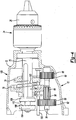
Fig. 1 is a perspective view of an exemplary multi-speed hammer drill constructed in accordance with the present invention; -
Fig. 2 is a partial cross-sectional view of a transmission of the hammer drill ofFig. 1 and shown with a first and second output gear in a nested position prior to engagement of the first output gear with a first reduction pinion in a first (low) speed position; -
Fig. 3 is a partial cross-sectional view of the transmission shown inFig. 2 and illustrated with the first gear meshingly engaged with the first reduction pinion in the low speed position; -
Fig. 4 is a partial cross-sectional view of the transmission shown inFig. 2 and illustrated with the guide plate initially moved along the guide rod to urge the second gear toward the second reduction pinion; -
Fig. 5 is a partial cross-sectional view of the transmission shown inFig. 2 and illustrated with the guide plate further advanced in a direction toward the second reduction pinion and with the first and second output gears partially nested prior to engagement of the second output gear with the second reduction pinion; -
Fig. 6 is a partial cross-sectional view of the transmission ofFig. 2 and shown with the second output gear meshingly engaged to the second reduction pinion in the second (high) speed position; -
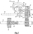
Fig. 7 is a perspective view of a speed shift assembly of the hammer drill ofFig. 1 and shown with a speed shift knob in the high speed position; -
Fig. 8 is a perspective view of the speed shift assembly ofFig. 7 and shown with the speed shift knob rotated about 90° clockwise (as viewed fromFig. 1 ) relative to the position illustrated inFig. 7 ; -
Fig. 9 is a perspective view of the speed shift assembly ofFig. 7 and shown with the speed shift knob rotated counterclockwise (as viewed fromFig. 1 ) relative to the position shown inFig. 7 ; -
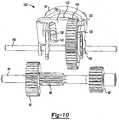
Fig. 10 is a perspective view of the speed shift assembly ofFig. 7 and shown with the speed shift knob rotated 180° relative to the position shown inFig. 7 and corresponding to the low speed position; -
Fig. 11 is a partial perspective view of a spindle lock ring constructed in accordance to additional features of the present teachings and illustrated assembled relative to a motor armature pinion; and -
Fig. 12 is a perspective view of the spindle lock ring ofFig. 11 . - While the following description is specifically directed toward a transmission and speed shift assembly for a hammer drill, the same may be implemented in other rotary output devices, such as other power drills, for example. Furthermore, while the following description specifically describes a two-speed transmission, the same may be applied to other transmissions, such as those having more than two speeds:
- With initial reference to
Fig. 1 , an exemplary hammer drill constructed in accordance with the present invention is shown and generally identified atreference numeral 10. Thehammer drill 10 can include ahousing 12 having ahandle 14. Thehousing 12 can generally comprise arearward housing 16, aforward housing 18 and ahandle housing 20. Therearward housing 16, theforward housing 18 and thehandle housing 20 can be formed of separate components or combined in various manners. For example, thehandle housing 20 can be combined as part of a single integral component forming at least some portions of therearward housing 16. Achuck assembly 24 can extend from theforward housing 18. Thechuck assembly 24 can generally include achuck body 26 and a plurality ofmovable jaws 28. Themovable jaws 28 can be configured in a convention manner to expand and contract for selectively retaining a drill bit (or other suitable implement) therein. - A
hammer shifter 30 can be rotatably disposed on thehousing 12. As will become appreciated from the following discussion, thehammer shifter 30 can be selectively rotatable between a first position that corresponds to a hammer drill mode and a second position that corresponds to a normal drilling mode. Aspeed shift knob 34 can be rotatably disposed on thehousing 12. In one example, thespeed shift knob 34 can comprise auser engagement portion 36 having anindicator 38. Indicia, collectively referred to at reference numeral 40 and individually identified atreference numerals 42 and 44 can be provided on thehousing 12 proximate to thespeed shift knob 34. In one example, theindicia 42 can correspond to a low speed position while the indicia 44 can correspond to a high speed position. - A
trigger 48 can be disposed on thehandle 14 of thehousing 12 for selectively activating amotor 50. Thehammer drill 10 according to this disclosure is an electric drill having apower cord 51. It can be appreciated, however, that thehammer drill 10 can be powered with other energy sources, such as a battery, pneumatically-based power supplies and/or combustion-based power supplies, for example. - With continued reference to
Fig. 1 and additional reference now toFigs. 2-6 , additional features of thehammer drill 10 will be described in greater detail. An output member 52 (Fig. 1 ) of themotor 50 can be rotatably coupled to a pinion shaft 54 (Fig. 2 ). Thepinion shaft 54 can include afirst reduction gear 56, afirst reduction pinion 58 and asecond reduction pinion 60. In some examples, thefirst reduction gear 56 can includeteeth 62 that are splined for rotation with themotor output 52 or other intermediate gears (not specifically shown). Thefirst reduction pinion 58 can includeteeth 64 that are dedicated for driving engagement while in the first (or low) speed output mode. Thesecond reduction pinion 60 can includeteeth 66 that can be configured for driving engagement while in the second (or high) speed output mode. - A floating
rotary output spindle 70 can be journaled in thehousing 12. Theoutput spindle 70 can be driven by the motor 50 (Fig. 1 ) through a transmission 72 (Fig. 2 ). Theoutput spindle 70 can extend outwardly from thehousing 12 to thechuck body 26 of thechuck assembly 24. Thetransmission 72 can generally comprise a first orlow output gear 76 and a second orhigh output gear 78. As will become appreciated from the following discussion, thesecond gear 78 can be configured to at least partially nest within an outer dimension of the first gear 76 (as shown inFig. 2 ), such as during shifting between the first (low) speed position (Fig. 3 ) and a second (high) speed position (Fig. 6 ). - The
first gear 76 can generally comprise an outercircumferential sidewall 80 and a firstannular depression 82.Teeth 84 can be formed around thecircumferential sidewall 80 of thefirst gear 76. Thefirst gear 76 can have an axial thickness 88 (Fig. 3 ). Thesecond gear 78 can have a secondannular extension 90 and acircumferential sidewall 92. Teeth 94 (Fig. 3 ) can be formed around thecircumferential sidewall 92 of thesecond gear 78. Thesecond gear 78 can have anaxial thickness 98. Theteeth 84 on thefirst gear 76 can be configured to meshingly engage theteeth 64 on thefirst reduction pinion 58 in the low speed position (Fig. 3 ). Theteeth 94 on thesecond gear 78 can be configured to meshingly engage theteeth 66 on thesecond reduction pinion 60 when in the second speed position (Fig. 6 ). - With further reference now to
Figs. 3-6 , additional features of thetransmission 72 will be further described. A biasingmember 100 can be journaled around theoutput spindle 70 and positioned generally between thefirst gear 76 and thesecond gear 78. As will be described herein, the biasingmember 100 can be configured to urge thefirst gear 76 into meshed engagement with thefirst reduction pinion 58. Similarly, the biasingmember 100 can be configured to urge thesecond gear 78 into meshed engagement with thesecond reduction pinion 60. Thehammer drill 10 can include a pair of cooperatinghammer members hammer members forward housing 18. It is appreciated that thehammer members hammer drill 10. Thehammer member 104 can be an axially movable hammer member that is fixed for rotation with theoutput spindle 70. Thehammer member 104 can be permitted limited axial movement, but not permitted to rotate with theoutput spindle 70. Thehammer member 106 can be carried by theoutput spindle 70 conjoint rotation therewith by press-fitting or otherwise suitable construction. - The
hammer members teeth output spindle 70 in the hammer drill mode of operation. Rotation of thehammer shifter 30 can influence engagement of therespective hammer members - With specific reference now to
Figs. 7-10 , additional features of thehammer drill 10 will be further described. Thehammer drill 10 can further comprise aspeed shift assembly 120 that includes thespeed shift knob 34, ashift plate 122 and aguide plate 124. For clarity, thefirst gear 76 is not shown inFigs. 7-10 to better illustrate features of thespeed shift assembly 120. Thespeed shift assembly 120 can be used with the nesting first andsecond gears speed shift assembly 120 can be used with thetransmission 72. According to one example, theshift plate 122 can be fixed for rotation with thespeed shift knob 34 and include anactuator pin 126 extending proud therefrom. Thespeed shift knob 34 can further comprise a pair of spring-biased pins 130 (Figs. 7 and8 ). Theguide plate 124 can generally comprise aU-shaped body 132 having a pair of opposingside flanges side flanges intermediate portion 138. Theintermediate portion 138 can define aslot 140 that receives theactuator pin 126. Theguide plate 124 can includemounts guide rod 150. - The
speed shift assembly 120 is illustrated inFig. 7 in the second (or high) speed position. In the second speed position, thesecond gear 78 is meshingly engaged to thesecond reduction pinion 60. Rotation of thespeed shift knob 34 can cause theactuator pin 126 to travel along theslot 140. The configuration of theshift assembly 120 according to the present teachings allows for rotation of thespeed shift knob 34 in either of the clockwise or counterclockwise directions. Furthermore, thespeed shift knob 34 is configured for complete 360° rotation in either direction without encountering any hard stops. In one example, as the user rotates thespeed shift knob 34 in the clockwise direction (as viewed fromFig. 1 ) 90° from the position shown inFig. 7 to the position shown inFig. 8 , theactuator pin 126 will be guided along theslot 140. - Movement of the
actuator pin 126 along theslot 140 can cause theguide plate 124 to slidably translate in a direction leftward as viewed fromFig. 7 . The springbiased pins 130 can be configured to selectively locate within a complementary depression provided in theforward housing 18 to provide a user with tactile feedback indicating that thespeed shift knob 34 has been sufficiently located into either of the low speed position (indicator 38 aligned with thelow speed indicia 42,Fig. 1 ) or the high speed position (indicator 38 aligned with the high speed indicia 44,Fig. 1 ).Figs. 9 and10 illustrate thespeed shift knob 34 rotated at various positions. - Returning now to
Figs. 2-6 , operation of thetransmission 72 andspeed shift assembly 120 according to various examples of the present teachings will be described. As illustrated inFig. 2 , thespeed shift knob 34 has been rotated to the low speed position causing theflange 136 to urge thesecond gear 78 into the nesting relationship with thefirst gear 76. While in a nested position, a thickness oraxial distance 158 can be provided between an outermost surface of the first gear 76 (that opposes the flange 134) and an outermost surface of the second gear 78 (that opposes the flange 136). The thickness oraxial distance 158 is less than a sum of theaxial thickness 88 of thefirst gear 76 and theaxial thickness 98 of thesecond gear 78. Explained differently, while in the nested position (Fig. 2 ), the first andsecond gears annular depression 82 can define an axial length or distance 160 (Fig. 3 ). Thecircumferential sidewall 92 of thesecond gear 78 can have an axial length ordistance 162. According to one example, more than half of theaxial distance 162 of thecircumferential sidewall 92 can be nested into the axial distance 160 of theannular depression 82 of thefirst gear 76 in the nested position (Fig. 2 ). According to one example, substantially about 90% of the circumferential sidewall 92 (or axial distance 162) can be nested into the annular depression 82 (or axial distance 160) in the nested position. By way of example, the axial distance 160 can be about 7.2mm and theaxial distance 162 can be about 8mm. Other dimensions are contemplated. Furthermore, various features may be modified to accommodate up to 100% of thecircumferential sidewall 92 into theannular depression 82. - While in the position shown in
Fig. 2 , the biasingmember 100 is compressed and providing an outward biasing force (in a direction leftward as viewed inFig. 2 ) against thefirst gear 76. The biasing force can facilitate movement of thefirst gear 76 into meshing alignment with thefirst reduction pinion 58. In this regard, the biasingmember 100 can urge thefirst gear 76 leftward until therespective teeth 84 on thefirst output gear 76 align with theteeth 64 on thefirst reduction pinion 58. Once therespective teeth first gear 76 slidably translates along theoutput spindle 70 to the position shown inFig. 3 . Once in the position shown inFig. 3 , thelow gear 76 is meshed for rotation with thefirst reduction pinion 58 in the low speed position. - When the user rotates the
speed shift knob 34 toward the high speed position, theflange 134 urges thefirst gear 76 rightward and out of meshing engagement with theteeth 64 of the first reduction pinion 58 (seeFigs. 4-5 ). In some examples where thesecond gear 78 does not initially align for meshing engagement with thesecond reduction pinion 60, thesecond gear 78 can at least partially nest into the first gear 76 (Fig. 5 ). Again, the biasingmember 100 can bias thesecond gear 78 in a direction rightward until a time at which theteeth 94 of thesecond gear 78 are aligned to meshingly engage theteeth 66 of thesecond reduction pinion 60. At such a time, thesecond gear 78 will be further biased rightward into the position shown inFig. 6 . With thesecond gear 78 advanced to the position shown inFig. 6 , theteeth 66 of thesecond reduction pinion 60 are meshingly engaged with theteeth 94 of thesecond gear 78 and thetransmission 72 will operate in the high speed mode. - Turning now to
Figs. 11 and 12 , aspindle lock ring 170 constructed in accordance to additional features will be described. Thespindle lock ring 170 can be used with amulti-speed transmission 72 discussed herein or alternatively with a single speed transmission. In general, thespindle lock ring 170 can surround an output spindle 70'. Thespindle lock ring 170 can be fixed for rotation relative to the output spindle 70'. Thespindle lock ring 170 can have abody 172 that includes aradial projection portion 174. Abore 176 can be formed through theradial projection portion 174 of thebody 172. Thebore 176 can define a through bore or a blind bore. Thebore 176 of thespindle lock ring 170 can receive at least a portion of a motor armature pinion 54'. The motor armature pinion 54' can haveteeth 184 that are threadably meshed for rotation withteeth 186 of anoutput gear 188. Thespindle lock ring 170 can support a portion of the motor armature pinion 54' and inhibit deflection of the motor armature pinion 54' away from theoutput gear 188 such as during a stall condition. For example, if the power drill locks up or is in a stall condition, the motor armature pinion 54' can have a tendency to deflect away from theoutput gear 188. The structural support provided on the motor armature pinion 54' by the bore of thespindle lock ring 170 can inhibit or resist such this deflection. Theoutput gear 188 can be configured as a single output gear or can be part of a multiple output gear configuration as described above with cooperation with theoutput spindle 70. - While the invention has been described in the specification and illustrated in the drawings with reference to various embodiments, it will be understood by those skilled in the art that various changes may be made and equivalents may be substituted for elements thereof without departing from the scope of the invention as defined in the claims. For example, while the
second gear 78 is shown toward the front of theforward housing 18, the relative positions of the first andsecond gears first gear 76 is toward the front of theforward housing 18. Furthermore, the mixing and matching of features, elements and/or functions between various embodiments is expressly contemplated herein so that one of ordinary skill in the art would appreciate from this disclosure that features, elements and/or functions of one embodiment may be incorporated into another embodiment as appropriate, unless described otherwise above.
Claims (13)
- A power tool (10) that includes:a housing (12) having a motor (50) including an output member (52);a rotary output spindle (70, 70') journaled in the housing;a transmission (72) disposed in the housing and including a first output gear (76) and a second output gear (78), wherein the transmission is arranged to selectively couple the output member to the output spindle through the first output gear or the second output gear for rotating the output spindle at a first speed or a second speed, respectively; anda speed shift assembly (120) that includes:a guide member (124) that influences movement of a said output gear; anda user engageable member (34) that is movable between a first speed position that corresponds to the first output gear being coupled for rotation with the output member and a second speed position that corresponds to the second output gear being coupled for rotation with the output member wherein movement between the first and second positions causes the second output gear to at least partially nest into the first output gear;characterized in that the guide member (124) selectively influences movement of the first output gear and/or the second output gear, and the power tool includes a biasing member (100) disposed between the first and second output gears.
- The power tool of claim 1 characterized in that the first output gear includes an annular depression (82) that selectively receives an annular extension (90) on the second output gear in a nested position.
- The power tool of claim 1 or claim 2 characterized in that the first output gear includes a first circumferential sidewall (80) and the second output gear includes a second circumferential sidewall (92), wherein the first circumferential sidewall at least partially surrounds the second circumferential sidewall in the nested position.
- The power tool of claim 3 characterized in that more than half of an axial length (162) of the second circumferential sidewall is nested into an axial length (160) of the annular depression in the nested position.
- The power tool of claim 4 characterized in that substantially about 90% of the axial length of the second circumferential sidewall is nested into the axial length of the annular depression in the nested position.
- The power tool of any preceding claim characterized in that the biasing member is configured to urge the first output gear away from the second output gear while complementary teeth (84, 64) on the first output gear and the output member align during engagement of the first output gear with the output member.
- The power tool of any preceding claim characterized in that the biasing member is configured to urge the second output gear away from the first output gear while complementary teeth (94, 66) on the second output gear and the output member align during engagement of the second output gear with the output member.
- The power tool of tool any preceding claim characterized in that the guide member comprises a U-shaped body (132) having opposing side flanges (134, 136) connected by an intermediate portion (138), wherein the opposing side flanges alternatively engage the first or second output gears during shifting between the first and second speed positions, respectively.
- The power tool of claim 8 characterized in that the intermediate portion (138) defines a slot (140) that is configured to receive an actuator pin (126) associated with the user engageable member and wherein the actuator pin is guided along the slot during movement of the user engageable member between the first and second speed positions.
- The power tool of claim 9 characterized in that the user engageable member comprises a knob configured for complete 360 degree rotation around an axis and wherein rotation of the knob influences linear translation of the guide member along a guide rod (150) during movement of the user engageable member between the first and second positions.
- The power tool of any preceding claim characterized in that the guide plate has first and second flanges (134, 136) that are configured to selectively and alternatively influence axial translation of the first and second output gears, respectively; and wherein an axial distance (158) measured between an outermost surface of the first gear that opposes the first flange and an outermost surface of the second gear that opposes the second flange, while in the nested position, is less than a sum of the first and second axial thicknesses (88, 98).
- The power tool of any preceding claim, characterized in that it further includes a rotatably fixed hammer member (104) and a rotatable hammer member (106) each mounted concentrically about the output spindle (70), the rotatable hammer member being mounted on the spindle to rotate therewith, the rotatable hammer member cooperating with the rotatably fixed hammer member to deliver vibratory impacts to the output spindle in a hammer drilling mode.
- The power tool of any preceding claim, characterized in that it further includes a spindle lock ring (170) that surrounds the output spindle and defines a receiving portion (174) that engages a motor pinion (54') associated with the output member and wherein the receiving portion defines a bore (176) that at least partially receives a portion of the motor pinion.
Applications Claiming Priority (1)
| Application Number | Priority Date | Filing Date | Title |
|---|---|---|---|
| US12/911,365 US8714888B2 (en) | 2010-10-25 | 2010-10-25 | Power tool transmission |
Publications (3)
| Publication Number | Publication Date |
|---|---|
| EP2444205A2 EP2444205A2 (en) | 2012-04-25 |
| EP2444205A3 EP2444205A3 (en) | 2013-09-25 |
| EP2444205B1 true EP2444205B1 (en) | 2016-05-18 |
Family
ID=44860260
Family Applications (1)
| Application Number | Title | Priority Date | Filing Date |
|---|---|---|---|
| EP11186248.8A Active EP2444205B1 (en) | 2010-10-25 | 2011-10-21 | Power Tool Transmission |
Country Status (3)
| Country | Link |
|---|---|
| US (1) | US8714888B2 (en) |
| EP (1) | EP2444205B1 (en) |
| CN (1) | CN202045386U (en) |
Families Citing this family (14)
| Publication number | Priority date | Publication date | Assignee | Title |
|---|---|---|---|---|
| CN101758486B (en) * | 2010-01-21 | 2011-09-28 | 浙江海王电器有限公司 | Light single-button multifunctional electric hammer |
| US9862116B2 (en) * | 2014-11-20 | 2018-01-09 | Black & Decker Inc. | Dual speed gearboxes, transmissions, and apparatuses incorporating the same |
| US10328560B2 (en) * | 2015-02-23 | 2019-06-25 | Brian Romagnoli | Multi-mode drive mechanisms and tools incorporating the same |
| WO2016196918A1 (en) | 2015-06-05 | 2016-12-08 | Ingersoll-Rand Company | Power tool user interfaces |
| US11491616B2 (en) | 2015-06-05 | 2022-11-08 | Ingersoll-Rand Industrial U.S., Inc. | Power tools with user-selectable operational modes |
| US10418879B2 (en) * | 2015-06-05 | 2019-09-17 | Ingersoll-Rand Company | Power tool user interfaces |
| WO2016196979A1 (en) | 2015-06-05 | 2016-12-08 | Ingersoll-Rand Company | Impact tools with ring gear alignment features |
| WO2016196899A1 (en) | 2015-06-05 | 2016-12-08 | Ingersoll-Rand Company | Power tool housings |
| US10518399B2 (en) * | 2015-09-30 | 2019-12-31 | Chervon (Hk) Limited | Clutch device and power tool with clutch device |
| CN106352028A (en) * | 2016-05-28 | 2017-01-25 | 重庆万虎机电有限责任公司 | Mini-tiller, speed changing box and speed changing mechanism of speed changing box |
| US11014172B2 (en) * | 2016-12-01 | 2021-05-25 | Mitsubishi Heavy Industries, Ltd. | Drill and drilling device including the same |
| DE102017121717A1 (en) * | 2017-09-19 | 2019-03-21 | Metabowerke Gmbh | Actuator and gear assembly for a power tool |
| US11261964B2 (en) | 2018-05-17 | 2022-03-01 | Black & Decker Inc. | Compliant shifting mechanism and multi-speed power tool having same |
| CN109015918A (en) * | 2018-10-11 | 2018-12-18 | 江苏泰华消防电气设备有限公司 | A kind of construction material perforating device |
Family Cites Families (43)
| Publication number | Priority date | Publication date | Assignee | Title |
|---|---|---|---|---|
| US840055A (en) * | 1906-03-17 | 1907-01-01 | Frank A Ferguson | Change-speed gear. |
| US2978921A (en) | 1959-03-05 | 1961-04-11 | Gleason Works | Ring gear and differential case assembly |
| US3162250A (en) | 1961-12-14 | 1964-12-22 | Master Power Corp | Torque control means for power tools |
| US3972106A (en) | 1973-08-06 | 1976-08-03 | Caterpillar Tractor Co. | Pinned-on planetary ring gear assembly and salvage method |
| US4418766A (en) * | 1979-07-25 | 1983-12-06 | Black & Decker Inc. | Compact multi-speed hammer-drill |
| JPS6125705A (en) | 1984-07-16 | 1986-02-04 | Japan Storage Battery Co Ltd | Speed change mechanism of electric drill |
| JP2582321B2 (en) | 1992-03-09 | 1997-02-19 | 本田技研工業株式会社 | Planetary carrier |
| JPH07238998A (en) | 1994-03-01 | 1995-09-12 | Honda Motor Co Ltd | Supporting structure of ring gear support member in planetary gear drive |
| DE19902187A1 (en) | 1998-03-04 | 1999-09-16 | Scintilla Ag | Planetary gearing for use with hand tools e.g. electric screwdrivers etc. |
| US6142242A (en) | 1999-02-15 | 2000-11-07 | Makita Corporation | Percussion driver drill, and a changeover mechanism for changing over a plurality of operating modes of an apparatus |
| US6223833B1 (en) | 1999-06-03 | 2001-05-01 | One World Technologies, Inc. | Spindle lock and chipping mechanism for hammer drill |
| JP3688943B2 (en) * | 1999-08-26 | 2005-08-31 | 株式会社マキタ | Hammer drill |
| DE10029898A1 (en) | 2000-06-17 | 2001-12-20 | Bosch Gmbh Robert | Hand tool; has tool chuck rotated by driven motor and driven shaft and having clamp device and has stop device arranged on driven shaft to secure or release clamp device against casing part |
| US7101300B2 (en) | 2001-01-23 | 2006-09-05 | Black & Decker Inc. | Multispeed power tool transmission |
| US20050061524A1 (en) | 2001-01-23 | 2005-03-24 | Hagan Todd A. | Housing with functional overmold |
| US6676557B2 (en) | 2001-01-23 | 2004-01-13 | Black & Decker Inc. | First stage clutch |
| US6805207B2 (en) | 2001-01-23 | 2004-10-19 | Black & Decker Inc. | Housing with functional overmold |
| US6431289B1 (en) | 2001-01-23 | 2002-08-13 | Black & Decker Inc. | Multi-speed power tool transmission |
| US6502648B2 (en) | 2001-01-23 | 2003-01-07 | Black & Decker Inc. | 360 degree clutch collar |
| JP3685115B2 (en) | 2001-09-11 | 2005-08-17 | 豊田工機株式会社 | Planetary gear set |
| US6435285B1 (en) | 2002-01-04 | 2002-08-20 | Feng-Chun Tsai | Structure for enhancing torque output of electric drill |
| US6655470B1 (en) | 2002-12-23 | 2003-12-02 | Power Network Industry Co., Ltd. | Speed changing mechanism for tools |
| US6824491B2 (en) | 2003-03-25 | 2004-11-30 | Power Network Industry Co., Ltd. | Power transmission device with automatic speed switching mechanism |
| US6796921B1 (en) | 2003-05-30 | 2004-09-28 | One World Technologies Limited | Three speed rotary power tool |
| US20050070399A1 (en) | 2003-09-26 | 2005-03-31 | Molon Motor & Coil Corp. | Planetary gear motor assembly and method of manufacture |
| JP2005118961A (en) | 2003-10-17 | 2005-05-12 | Makita Corp | Driver drill |
| JP4227028B2 (en) | 2004-01-09 | 2009-02-18 | 株式会社マキタ | Screwdriver drill |
| US7308948B2 (en) | 2004-10-28 | 2007-12-18 | Makita Corporation | Electric power tool |
| US7314097B2 (en) | 2005-02-24 | 2008-01-01 | Black & Decker Inc. | Hammer drill with a mode changeover mechanism |
| US7942211B2 (en) | 2005-08-29 | 2011-05-17 | Demain Technology, Pty Ltd | Power tool |
| US7980324B2 (en) | 2006-02-03 | 2011-07-19 | Black & Decker Inc. | Housing and gearbox for drill or driver |
| EP1857228B1 (en) | 2006-05-19 | 2008-07-09 | Black & Decker, Inc. | Mode change mechanism for a power tool |
| US8303449B2 (en) | 2006-08-01 | 2012-11-06 | Techtronic Power Tools Technology Limited | Automatic transmission for a power tool |
| US7513845B2 (en) | 2006-08-01 | 2009-04-07 | Eastway Fair Company Limited | Variable speed transmission for a power tool |
| DE102006000515A1 (en) * | 2006-12-12 | 2008-06-19 | Hilti Ag | Electric hand tool |
| US7455615B2 (en) | 2007-01-04 | 2008-11-25 | Hsin-Chih Chung Lee | Transmission mechanism |
| US7494437B2 (en) | 2007-01-04 | 2009-02-24 | Ting Kuang Chen | Impact power tool |
| JP5030601B2 (en) | 2007-01-22 | 2012-09-19 | 株式会社マキタ | Electric tool |
| JP4609489B2 (en) | 2007-12-25 | 2011-01-12 | パナソニック電工株式会社 | Electric tool |
| US20090200758A1 (en) | 2008-02-07 | 2009-08-13 | Chin Hung Lam | Auto Locking Chuck |
| JP2009190134A (en) | 2008-02-15 | 2009-08-27 | Makita Corp | Battery-powered power tool |
| US8251158B2 (en) | 2008-11-08 | 2012-08-28 | Black & Decker Inc. | Multi-speed power tool transmission with alternative ring gear configuration |
| EP2216114B1 (en) | 2009-02-05 | 2013-08-28 | Techtronic Power Tools Technology Limited | Power tool chuck assembly with hammer mechanism |
-
2010
- 2010-10-25 US US12/911,365 patent/US8714888B2/en active Active
-
2011
- 2011-03-18 CN CN201120072553.XU patent/CN202045386U/en not_active Expired - Fee Related
- 2011-10-21 EP EP11186248.8A patent/EP2444205B1/en active Active
Also Published As
| Publication number | Publication date |
|---|---|
| EP2444205A3 (en) | 2013-09-25 |
| US8714888B2 (en) | 2014-05-06 |
| US20120099936A1 (en) | 2012-04-26 |
| CN202045386U (en) | 2011-11-23 |
| EP2444205A2 (en) | 2012-04-25 |
Similar Documents
| Publication | Publication Date | Title |
|---|---|---|
| EP2444205B1 (en) | Power Tool Transmission | |
| EP2184138B1 (en) | Multi-speed power tool transmission with alternative ring gear configuration | |
| EP2062694B1 (en) | Multi-speed drill and transmission with a clutch for low-gear only | |
| EP2062695B1 (en) | Transmission Sub-Assembly for a Multi-Mode Drill | |
| US7735575B2 (en) | Hammer drill with hard hammer support structure | |
| US7798245B2 (en) | Multi-mode drill with an electronic switching arrangement | |
| US7717192B2 (en) | Multi-mode drill with mode collar | |
| EP2875906B1 (en) | Multi-speed cycloidal transmission | |
| US7717191B2 (en) | Multi-mode hammer drill with shift lock | |
| US8047057B2 (en) | Output mode switching apparatus | |
| US8251156B2 (en) | Compliant shifting mechanism for right angle drill | |
| US9283667B2 (en) | Power tool with torque clutch | |
| WO2014156471A1 (en) | Electric tool | |
| JP2012006101A (en) | Impact tool | |
| JP2005254374A (en) | Impact screw driver |
Legal Events
| Date | Code | Title | Description |
|---|---|---|---|
| AK | Designated contracting states |
Kind code of ref document: A2 Designated state(s): AL AT BE BG CH CY CZ DE DK EE ES FI FR GB GR HR HU IE IS IT LI LT LU LV MC MK MT NL NO PL PT RO RS SE SI SK SM TR |
|
| AX | Request for extension of the european patent |
Extension state: BA ME |
|
| PUAI | Public reference made under article 153(3) epc to a published international application that has entered the european phase |
Free format text: ORIGINAL CODE: 0009012 |
|
| PUAL | Search report despatched |
Free format text: ORIGINAL CODE: 0009013 |
|
| AK | Designated contracting states |
Kind code of ref document: A3 Designated state(s): AL AT BE BG CH CY CZ DE DK EE ES FI FR GB GR HR HU IE IS IT LI LT LU LV MC MK MT NL NO PL PT RO RS SE SI SK SM TR |
|
| AX | Request for extension of the european patent |
Extension state: BA ME |
|
| RIC1 | Information provided on ipc code assigned before grant |
Ipc: B25F 5/00 20060101AFI20130816BHEP |
|
| 17P | Request for examination filed |
Effective date: 20140324 |
|
| RBV | Designated contracting states (corrected) |
Designated state(s): AL AT BE BG CH CY CZ DE DK EE ES FI FR GB GR HR HU IE IS IT LI LT LU LV MC MK MT NL NO PL PT RO RS SE SI SK SM TR |
|
| GRAP | Despatch of communication of intention to grant a patent |
Free format text: ORIGINAL CODE: EPIDOSNIGR1 |
|
| INTG | Intention to grant announced |
Effective date: 20160303 |
|
| GRAS | Grant fee paid |
Free format text: ORIGINAL CODE: EPIDOSNIGR3 |
|
| GRAA | (expected) grant |
Free format text: ORIGINAL CODE: 0009210 |
|
| AK | Designated contracting states |
Kind code of ref document: B1 Designated state(s): AL AT BE BG CH CY CZ DE DK EE ES FI FR GB GR HR HU IE IS IT LI LT LU LV MC MK MT NL NO PL PT RO RS SE SI SK SM TR |
|
| REG | Reference to a national code |
Ref country code: GB Ref legal event code: FG4D |
|
| REG | Reference to a national code |
Ref country code: CH Ref legal event code: EP |
|
| REG | Reference to a national code |
Ref country code: IE Ref legal event code: FG4D Ref country code: AT Ref legal event code: REF Ref document number: 800014 Country of ref document: AT Kind code of ref document: T Effective date: 20160615 |
|
| REG | Reference to a national code |
Ref country code: DE Ref legal event code: R096 Ref document number: 602011026671 Country of ref document: DE |
|
| REG | Reference to a national code |
Ref country code: NL Ref legal event code: MP Effective date: 20160518 |
|
| REG | Reference to a national code |
Ref country code: LT Ref legal event code: MG4D |
|
| PG25 | Lapsed in a contracting state [announced via postgrant information from national office to epo] |
Ref country code: NL Free format text: LAPSE BECAUSE OF FAILURE TO SUBMIT A TRANSLATION OF THE DESCRIPTION OR TO PAY THE FEE WITHIN THE PRESCRIBED TIME-LIMIT Effective date: 20160518 Ref country code: LT Free format text: LAPSE BECAUSE OF FAILURE TO SUBMIT A TRANSLATION OF THE DESCRIPTION OR TO PAY THE FEE WITHIN THE PRESCRIBED TIME-LIMIT Effective date: 20160518 Ref country code: NO Free format text: LAPSE BECAUSE OF FAILURE TO SUBMIT A TRANSLATION OF THE DESCRIPTION OR TO PAY THE FEE WITHIN THE PRESCRIBED TIME-LIMIT Effective date: 20160818 Ref country code: FI Free format text: LAPSE BECAUSE OF FAILURE TO SUBMIT A TRANSLATION OF THE DESCRIPTION OR TO PAY THE FEE WITHIN THE PRESCRIBED TIME-LIMIT Effective date: 20160518 |
|
| REG | Reference to a national code |
Ref country code: AT Ref legal event code: MK05 Ref document number: 800014 Country of ref document: AT Kind code of ref document: T Effective date: 20160518 |
|
| PG25 | Lapsed in a contracting state [announced via postgrant information from national office to epo] |
Ref country code: ES Free format text: LAPSE BECAUSE OF FAILURE TO SUBMIT A TRANSLATION OF THE DESCRIPTION OR TO PAY THE FEE WITHIN THE PRESCRIBED TIME-LIMIT Effective date: 20160518 Ref country code: HR Free format text: LAPSE BECAUSE OF FAILURE TO SUBMIT A TRANSLATION OF THE DESCRIPTION OR TO PAY THE FEE WITHIN THE PRESCRIBED TIME-LIMIT Effective date: 20160518 Ref country code: LV Free format text: LAPSE BECAUSE OF FAILURE TO SUBMIT A TRANSLATION OF THE DESCRIPTION OR TO PAY THE FEE WITHIN THE PRESCRIBED TIME-LIMIT Effective date: 20160518 Ref country code: PT Free format text: LAPSE BECAUSE OF FAILURE TO SUBMIT A TRANSLATION OF THE DESCRIPTION OR TO PAY THE FEE WITHIN THE PRESCRIBED TIME-LIMIT Effective date: 20160919 Ref country code: RS Free format text: LAPSE BECAUSE OF FAILURE TO SUBMIT A TRANSLATION OF THE DESCRIPTION OR TO PAY THE FEE WITHIN THE PRESCRIBED TIME-LIMIT Effective date: 20160518 Ref country code: SE Free format text: LAPSE BECAUSE OF FAILURE TO SUBMIT A TRANSLATION OF THE DESCRIPTION OR TO PAY THE FEE WITHIN THE PRESCRIBED TIME-LIMIT Effective date: 20160518 Ref country code: GR Free format text: LAPSE BECAUSE OF FAILURE TO SUBMIT A TRANSLATION OF THE DESCRIPTION OR TO PAY THE FEE WITHIN THE PRESCRIBED TIME-LIMIT Effective date: 20160819 |
|
| PG25 | Lapsed in a contracting state [announced via postgrant information from national office to epo] |
Ref country code: IT Free format text: LAPSE BECAUSE OF FAILURE TO SUBMIT A TRANSLATION OF THE DESCRIPTION OR TO PAY THE FEE WITHIN THE PRESCRIBED TIME-LIMIT Effective date: 20160518 |
|
| PG25 | Lapsed in a contracting state [announced via postgrant information from national office to epo] |
Ref country code: SK Free format text: LAPSE BECAUSE OF FAILURE TO SUBMIT A TRANSLATION OF THE DESCRIPTION OR TO PAY THE FEE WITHIN THE PRESCRIBED TIME-LIMIT Effective date: 20160518 Ref country code: RO Free format text: LAPSE BECAUSE OF FAILURE TO SUBMIT A TRANSLATION OF THE DESCRIPTION OR TO PAY THE FEE WITHIN THE PRESCRIBED TIME-LIMIT Effective date: 20160518 Ref country code: CZ Free format text: LAPSE BECAUSE OF FAILURE TO SUBMIT A TRANSLATION OF THE DESCRIPTION OR TO PAY THE FEE WITHIN THE PRESCRIBED TIME-LIMIT Effective date: 20160518 Ref country code: EE Free format text: LAPSE BECAUSE OF FAILURE TO SUBMIT A TRANSLATION OF THE DESCRIPTION OR TO PAY THE FEE WITHIN THE PRESCRIBED TIME-LIMIT Effective date: 20160518 Ref country code: DK Free format text: LAPSE BECAUSE OF FAILURE TO SUBMIT A TRANSLATION OF THE DESCRIPTION OR TO PAY THE FEE WITHIN THE PRESCRIBED TIME-LIMIT Effective date: 20160518 |
|
| REG | Reference to a national code |
Ref country code: DE Ref legal event code: R097 Ref document number: 602011026671 Country of ref document: DE |
|
| PG25 | Lapsed in a contracting state [announced via postgrant information from national office to epo] |
Ref country code: AT Free format text: LAPSE BECAUSE OF FAILURE TO SUBMIT A TRANSLATION OF THE DESCRIPTION OR TO PAY THE FEE WITHIN THE PRESCRIBED TIME-LIMIT Effective date: 20160518 Ref country code: PL Free format text: LAPSE BECAUSE OF FAILURE TO SUBMIT A TRANSLATION OF THE DESCRIPTION OR TO PAY THE FEE WITHIN THE PRESCRIBED TIME-LIMIT Effective date: 20160518 Ref country code: BE Free format text: LAPSE BECAUSE OF FAILURE TO SUBMIT A TRANSLATION OF THE DESCRIPTION OR TO PAY THE FEE WITHIN THE PRESCRIBED TIME-LIMIT Effective date: 20160518 Ref country code: SM Free format text: LAPSE BECAUSE OF FAILURE TO SUBMIT A TRANSLATION OF THE DESCRIPTION OR TO PAY THE FEE WITHIN THE PRESCRIBED TIME-LIMIT Effective date: 20160518 |
|
| PLBE | No opposition filed within time limit |
Free format text: ORIGINAL CODE: 0009261 |
|
| STAA | Information on the status of an ep patent application or granted ep patent |
Free format text: STATUS: NO OPPOSITION FILED WITHIN TIME LIMIT |
|
| 26N | No opposition filed |
Effective date: 20170221 |
|
| PG25 | Lapsed in a contracting state [announced via postgrant information from national office to epo] |
Ref country code: SI Free format text: LAPSE BECAUSE OF FAILURE TO SUBMIT A TRANSLATION OF THE DESCRIPTION OR TO PAY THE FEE WITHIN THE PRESCRIBED TIME-LIMIT Effective date: 20160518 |
|
| REG | Reference to a national code |
Ref country code: CH Ref legal event code: PL |
|
| PG25 | Lapsed in a contracting state [announced via postgrant information from national office to epo] |
Ref country code: MC Free format text: LAPSE BECAUSE OF FAILURE TO SUBMIT A TRANSLATION OF THE DESCRIPTION OR TO PAY THE FEE WITHIN THE PRESCRIBED TIME-LIMIT Effective date: 20160518 |
|
| REG | Reference to a national code |
Ref country code: IE Ref legal event code: MM4A |
|
| REG | Reference to a national code |
Ref country code: FR Ref legal event code: ST Effective date: 20170630 |
|
| PG25 | Lapsed in a contracting state [announced via postgrant information from national office to epo] |
Ref country code: FR Free format text: LAPSE BECAUSE OF NON-PAYMENT OF DUE FEES Effective date: 20161102 Ref country code: CH Free format text: LAPSE BECAUSE OF NON-PAYMENT OF DUE FEES Effective date: 20161031 Ref country code: LI Free format text: LAPSE BECAUSE OF NON-PAYMENT OF DUE FEES Effective date: 20161031 |
|
| PG25 | Lapsed in a contracting state [announced via postgrant information from national office to epo] |
Ref country code: LU Free format text: LAPSE BECAUSE OF NON-PAYMENT OF DUE FEES Effective date: 20161021 |
|
| PG25 | Lapsed in a contracting state [announced via postgrant information from national office to epo] |
Ref country code: IE Free format text: LAPSE BECAUSE OF NON-PAYMENT OF DUE FEES Effective date: 20161021 |
|
| PG25 | Lapsed in a contracting state [announced via postgrant information from national office to epo] |
Ref country code: HU Free format text: LAPSE BECAUSE OF FAILURE TO SUBMIT A TRANSLATION OF THE DESCRIPTION OR TO PAY THE FEE WITHIN THE PRESCRIBED TIME-LIMIT; INVALID AB INITIO Effective date: 20111021 Ref country code: CY Free format text: LAPSE BECAUSE OF FAILURE TO SUBMIT A TRANSLATION OF THE DESCRIPTION OR TO PAY THE FEE WITHIN THE PRESCRIBED TIME-LIMIT Effective date: 20160518 |
|
| PG25 | Lapsed in a contracting state [announced via postgrant information from national office to epo] |
Ref country code: TR Free format text: LAPSE BECAUSE OF FAILURE TO SUBMIT A TRANSLATION OF THE DESCRIPTION OR TO PAY THE FEE WITHIN THE PRESCRIBED TIME-LIMIT Effective date: 20160518 Ref country code: MK Free format text: LAPSE BECAUSE OF FAILURE TO SUBMIT A TRANSLATION OF THE DESCRIPTION OR TO PAY THE FEE WITHIN THE PRESCRIBED TIME-LIMIT Effective date: 20160518 Ref country code: IS Free format text: LAPSE BECAUSE OF FAILURE TO SUBMIT A TRANSLATION OF THE DESCRIPTION OR TO PAY THE FEE WITHIN THE PRESCRIBED TIME-LIMIT Effective date: 20160518 Ref country code: MT Free format text: LAPSE BECAUSE OF NON-PAYMENT OF DUE FEES Effective date: 20161031 |
|
| PG25 | Lapsed in a contracting state [announced via postgrant information from national office to epo] |
Ref country code: BG Free format text: LAPSE BECAUSE OF FAILURE TO SUBMIT A TRANSLATION OF THE DESCRIPTION OR TO PAY THE FEE WITHIN THE PRESCRIBED TIME-LIMIT Effective date: 20160518 |
|
| PG25 | Lapsed in a contracting state [announced via postgrant information from national office to epo] |
Ref country code: AL Free format text: LAPSE BECAUSE OF FAILURE TO SUBMIT A TRANSLATION OF THE DESCRIPTION OR TO PAY THE FEE WITHIN THE PRESCRIBED TIME-LIMIT Effective date: 20160518 |
|
| PGFP | Annual fee paid to national office [announced via postgrant information from national office to epo] |
Ref country code: GB Payment date: 20230831 Year of fee payment: 13 |
|
| PGFP | Annual fee paid to national office [announced via postgrant information from national office to epo] |
Ref country code: DE Payment date: 20230830 Year of fee payment: 13 |