EP2443564B1 - Data compression for reducing storage requirements in a database system - Google Patents
Data compression for reducing storage requirements in a database system Download PDFInfo
- Publication number
- EP2443564B1 EP2443564B1 EP10790192.8A EP10790192A EP2443564B1 EP 2443564 B1 EP2443564 B1 EP 2443564B1 EP 10790192 A EP10790192 A EP 10790192A EP 2443564 B1 EP2443564 B1 EP 2443564B1
- Authority
- EP
- European Patent Office
- Prior art keywords
- data
- row
- compression
- page
- column
- Prior art date
- Legal status (The legal status is an assumption and is not a legal conclusion. Google has not performed a legal analysis and makes no representation as to the accuracy of the status listed.)
- Active
Links
- 238000013144 data compression Methods 0.000 title description 5
- 238000007906 compression Methods 0.000 claims description 67
- 230000006835 compression Effects 0.000 claims description 65
- 238000000034 method Methods 0.000 claims description 41
- 238000013500 data storage Methods 0.000 claims description 5
- 238000004590 computer program Methods 0.000 claims description 4
- 239000013589 supplement Substances 0.000 claims 1
- 230000015654 memory Effects 0.000 description 18
- 230000008569 process Effects 0.000 description 9
- 238000013459 approach Methods 0.000 description 5
- 238000010586 diagram Methods 0.000 description 5
- 101100328886 Caenorhabditis elegans col-2 gene Proteins 0.000 description 4
- 238000004891 communication Methods 0.000 description 4
- 238000013508 migration Methods 0.000 description 4
- 238000012545 processing Methods 0.000 description 4
- 238000000605 extraction Methods 0.000 description 3
- 238000007726 management method Methods 0.000 description 3
- 230000005012 migration Effects 0.000 description 3
- 238000012986 modification Methods 0.000 description 3
- 230000004048 modification Effects 0.000 description 3
- 230000008901 benefit Effects 0.000 description 2
- 238000010276 construction Methods 0.000 description 2
- 230000001419 dependent effect Effects 0.000 description 2
- 230000006870 function Effects 0.000 description 2
- 238000010606 normalization Methods 0.000 description 2
- 101100328884 Caenorhabditis elegans sqt-3 gene Proteins 0.000 description 1
- 101100237842 Xenopus laevis mmp18 gene Proteins 0.000 description 1
- 230000003044 adaptive effect Effects 0.000 description 1
- 238000004458 analytical method Methods 0.000 description 1
- 238000003491 array Methods 0.000 description 1
- 230000006399 behavior Effects 0.000 description 1
- 230000005540 biological transmission Effects 0.000 description 1
- 230000007812 deficiency Effects 0.000 description 1
- 230000008030 elimination Effects 0.000 description 1
- 238000003379 elimination reaction Methods 0.000 description 1
- 238000005516 engineering process Methods 0.000 description 1
- 238000011156 evaluation Methods 0.000 description 1
- 238000004880 explosion Methods 0.000 description 1
- 239000003292 glue Substances 0.000 description 1
- 239000004973 liquid crystal related substance Substances 0.000 description 1
- 230000007246 mechanism Effects 0.000 description 1
- 230000003287 optical effect Effects 0.000 description 1
- 238000004806 packaging method and process Methods 0.000 description 1
- 230000002093 peripheral effect Effects 0.000 description 1
- 230000002085 persistent effect Effects 0.000 description 1
- 230000009467 reduction Effects 0.000 description 1
- 238000012546 transfer Methods 0.000 description 1
- 239000002699 waste material Substances 0.000 description 1
- 230000003936 working memory Effects 0.000 description 1
Images


Classifications
-
- G—PHYSICS
- G06—COMPUTING; CALCULATING OR COUNTING
- G06F—ELECTRIC DIGITAL DATA PROCESSING
- G06F16/00—Information retrieval; Database structures therefor; File system structures therefor
- G06F16/20—Information retrieval; Database structures therefor; File system structures therefor of structured data, e.g. relational data
- G06F16/22—Indexing; Data structures therefor; Storage structures
Definitions
- the present invention relates generally to database systems and, more particularly, to data compression in database systems.
- Relational databases are a common mechanism for storing information on computer systems while providing easy access to users.
- a typical relational database is an organized collection of related information stored as "records" having "fields" of information.
- a database of employees may have a record for each employee where each record contains fields designating specifics about the employee, such as name, home address, salary, and the like.
- a relational database management system or RDBMS is typically provided as a software cushion or layer.
- the RDBMS shields the database user from knowing or even caring about the underlying hardware-level details.
- all requests from users for access to the data are processed by the RDBMS. For example, information may be added or removed from data files, information retrieved from or updated in such files, and so forth, all without user knowledge of the underlying system implementation.
- the RDBMS provides users with a conceptual view of the database that is removed from the hardware level.
- the general construction and operation of database management systems is well known in the art. See e.g., Date, C., "An Introduction to Database Systems, Seventh Edition", Part I (especially Chapters 1-4), Addison Wesley, 2000 .
- Efficient data access is one of the properties provided by a database management system.
- a key challenge faced by relational database systems is the ever-growing database size. With increasing use of digital devices and ease of data flow on ubiquitous networks, the data explosion has accelerated in recent years. As regular database and table size has grown tremendously in recent years, data compression becomes increasing important even for databases. While row level compression and page level compression for databases have been introduced, a need remains for improved compression techniques to overcome deficiencies in these approaches without introducing new overhead. The present invention addresses this need.
- US 2006/0212625 discloses procedures for compression/migration of data.
- a data relay module migrates data from a logical volume in compression units comprising a set of a given number of data blocks.
- the data relay module stores the post-compression data into the migration destination logical volume and a correspondence relationship between the pre-migration and post-migration block sets is stored into a control table.
- US2008/0071818 discloses a technique for compressing data in a relational database.
- An embodiment includes identifying at least one data candidate of fixed length data type in at least one row of database data for compression based upon a predetermined threshold level and a boundary of compression, providing at least one bit within the at least one row for an identified data candidate according to the boundary of compression, and storing the at least one row as compressed data in the database system.
- the identified data candidates for compression include fixed length columns having lengths that do not fall below the predetermined threshold level in a row of data and the at least one bit comprises a bitmap for a length of the identified data candidates following compression.
- the identified data candidates for compression include redundant byte string data in a page of data, the redundant byte string data including matching data across columns having lengths that do not exceed the predetermined threshold level.
- FIG. 1 illustrates a general block diagram of a computer system (e.g., an IBM-compatible system) in which software-implemented processes of the present invention may be embodied.
- a computer system e.g., an IBM-compatible system
- software-implemented processes of the present invention may be embodied.
- system 100 comprises a central processing unit(s) (CPU) or processor(s) 101 coupled to a random-access memory (RAM) 102, a read-only memory (ROM) 103, a keyboard 106, a printer 107, a pointing device 108, a display or video adapter 104 connected to a display device 105, a removable (mass) storage device 115 (e.g., floppy disk, CD-ROM, CD-R, CD-RW, DVD, or the like), a fixed (mass) storage device 116 (e.g., hard disk), a communication (COMM) port(s) or interface(s) 110, a modem 112, and a network interface card (NIC) or controller 111 (e.g., Ethernet).
- a real time system clock is included with the system 100, in a conventional manner.
- CPU 101 comprises any suitable processor, such as a processor of the Intel Pentium family of microprocessors, for implementing the present invention.
- the CPU 101 communicates with other components of the system via a bi-directional system bus (including any necessary input/output (I/O) controller circuitry and other "glue" logic).
- the bus which includes address lines for addressing system memory, provides data transfer between and among the various components, as is well understood in the art.
- Random-access memory 102 serves as the working memory for the CPU 101. In a typical configuration, RAM of multiple megabytes or gigabytes is employed. More or less memory may be used without departing from the scope of the present invention.
- the read-only memory (ROM) 103 contains the basic input/output system code (BIOS)-a set of low-level routines in the ROM that application programs and the operating systems can use to interact with the hardware, including reading characters from the keyboard, outputting characters to printers, and so forth.
- BIOS basic input/output system code
- Mass storage devices 115, 116 provide persistent storage on fixed and removable media, such as magnetic, optical or magnetic-optical storage systems, flash memory, or any other available mass storage technology.
- the mass storage may be shared on a network, or it may be a dedicated mass storage.
- fixed storage 116 stores a body of program and data for directing operation of the computer system, including an operating system, user application programs, driver and other support files, as well as other data files of all sorts.
- the fixed storage 116 serves as the main hard disk for the system.
- program logic (including that which implements methodology of the present invention described below) is loaded from the removable storage 115 or fixed storage 116 into the main (RAM) memory 102, for execution by the CPU 101.
- the system 100 accepts user input from a keyboard 106 and pointing device 108, as well as speech-based input from a voice recognition system (not shown).
- the keyboard 106 permits selection of application programs, entry of keyboard-based input or data, and selection and manipulation of individual data objects displayed on the screen or display device 105.
- the pointing device 108 such as a mouse, track ball, pen device, or the like, permits selection and manipulation of objects on the display device. In this manner, these input devices support manual user input for any process running on the system.
- the computer system 100 displays text and/or graphic images and other data on the display device 105.
- the video adapter 104 which is interposed between the display device 105 and the system's bus, drives the display device 105.
- the video adapter 104 which includes video memory accessible to the CPU 101, provides circuitry that converts pixel data stored in the video memory to a raster signal suitable for use by a cathode ray tube (CRT) raster or liquid crystal display (LCD) monitor.
- CTR cathode ray tube
- LCD liquid crystal display
- a hard copy of the displayed information, or other information within the system 100 may be obtained from the printer 107, or other output device.
- Printer 107 may include, for instance, a HP LaserJet printer (available from Hewlett Packard of Palo Alto, Calif.), for creating hard copy images of output of the system.
- the system itself communicates with other devices (e.g., other computers) via the network interface card (NIC) 111 connected to a network (e.g., Ethernet network, Bluetooth wireless network, or the like), and/or modem 112 (e.g., 56K baud, ISDN, DSL, or cable modem), examples of which are available from 3Com of Santa Clara, Calif.
- the system 100 may also communicate with local occasionally-connected devices (e.g., serial cable-linked devices) via the communication (COMM) interface 110, which may include a RS-232 serial port, a Universal Serial Bus (USB) interface, or the like.
- Communication communication
- USB Universal Serial Bus
- IBM-compatible personal computers and server computers are available from a variety of vendors. Representative vendors include Dell Computers of Round Rock, Tex., Hewlett-Packard of Palo Alto, Calif., and IBM of Armonk, N.Y. Other suitable computers include Apple-compatible computers (e.g., Macintosh), which are available from Apple Computer of Cupertino, Calif., and Sun Solaris workstations, which are available from Sun Microsystems of Mountain View, Calif.
- Apple-compatible computers e.g., Macintosh
- Sun Solaris workstations which are available from Sun Microsystems of Mountain View, Calif.
- a software system is typically provided for controlling the operation of the computer system 100.
- the software system which is usually stored in system memory (RAM) 102 and on fixed storage (e.g., hard disk) 116, includes a kernel or operating system (OS) which manages low-level aspects of computer operation, including managing execution of processes, memory allocation, file input and output (I/O), and device I/O.
- the OS can be provided by a conventional operating system, Microsoft Windows NT, Microsoft Windows 2000, Microsoft Windows XP, or Microsoft Windows Vista (Microsoft Corporation of Redmond, Wash.) or an alternative operating system, such as the previously mentioned operating systems.
- the OS operates in conjunction with device drivers (e.g., "Winsock” driver--Windows' implementation of a TCP/IP stack) and the system BIOS microcode (i.e., ROM-based microcode), particularly when interfacing with peripheral devices.
- device drivers e.g., "Winsock” driver--Windows' implementation of a TCP/IP stack
- BIOS microcode i.e., ROM-based microcode
- client application software or “programs” i.e., set of processor-executable instructions
- the application(s) or other software intended for use on the computer system may be "loaded” into memory 102 from fixed storage 116 or may be downloaded from an Internet location (e.g., Web server).
- GUI graphical user interface
- the graphical user interface also serves to display the results of operation from the OS and application(s).
- FIG. 2 illustrates the general structure of a client/server database system 200 suitable for implementing the present invention.
- the system 200 comprises one or more client(s) 210 connected to a server 230 via a network 220.
- the client(s) 210 comprise one or more standalone terminals 211 connected to a database server system 240 using a conventional network.
- the terminals 211 may themselves comprise a plurality of standalone workstations, dumb terminals, or the like, or comprise personal computers (PCs) such as the above-described system 100.
- PCs personal computers
- client operating system such as a Microsoft® Windows client operating system (e.g., Microsoft® Windows 95/98, Windows 2000, or Windows XP).
- the database server system 240 which comprises Sybase® Adaptive Server® Enterprise (ASE) (available from Sybase, Inc. of Dublin, Calif.) in an exemplary embodiment, generally operates as an independent process (i.e., independently of the clients), running under a server operating system such as Microsoft® Windows NT, Windows 2000, or Windows XP (all from Microsoft Corporation of Redmond, Wash.), UNIX (Novell), Solaris (Sun), or Linux (Red Hat).
- the network 220 may be any one of a number of conventional network systems, including a Local Area Network (LAN) or Wide Area Network (WAN), as is known in the art (e.g., using Ethernet, IBM Token Ring, or the like).
- the network 220 includes functionality for packaging client calls in the well-known Structured Query Language (SQL) together with any parameter information into a format (of one or more packets) suitable for transmission to the database server system 240.
- SQL Structured Query Language
- the described computer hardware and software are presented for purposes of illustrating the basic underlying desktop and server computer components that may be employed for implementing the present invention. For purposes of discussion, the following description will present examples in which it will be assumed that there exist multiple server instances (e.g., database server nodes) in a cluster that communicate with one or more "clients" (e.g., personal computers or mobile devices).
- the present invention is not limited to any particular environment or device configuration. Instead, the present invention may be implemented in any type of system architecture or processing environment capable of supporting the methodologies of the present invention presented in detail below.
- client(s) 210 store data in, or retrieve data from, one or more database tables 250, as shown at FIG. 2 .
- Data in a relational database is stored as a series of tables, also called relations.
- each table itself comprises one or more "rows” or “records” (tuples) (e.g., row 255 as shown at FIG. 2 ).
- a typical database will contain many tables, each of which stores information about a particular type of entity.
- a table in a typical relational database may contain anywhere from a few rows to millions of rows.
- a row is divided into fields or columns; each field represents one particular attribute of the given row.
- a row corresponding to an employee record may include information about the employee's ID Number, Last Name and First Initial, Position, Date Hired, Social Security Number (SSN), and Salary.
- Each of these categories represents a database field.
- Position is one field
- Date Hired is another, and so on.
- tables are easy for users to understand and use.
- the flexibility of tables permits a user to define relationships between various items of data, as needed.
- a typical record includes several categories of information about an individual person, place, or thing.
- Each row in a table is uniquely identified by a record ID (RID), which can be used as a pointer to a given row.
- RID record ID
- SQL Structured Query Language
- DML data manipulation language
- DDL data definition language
- the clients 210 issue one or more SQL commands to the server 230.
- SQL commands may specify, for instance, a query for retrieving particular data (i.e., data records meeting the query condition) from the database table(s) 250.
- the clients 210 also have the ability to issue commands to insert new rows of data records into the table(s), or to update and/or delete existing records in the table(s).
- the SQL statements received from the client(s) 210 are processed by the engine 260 of the database server system 240.
- the engine 260 itself comprises a parser 261, a normalizer 263, a compiler 265, an execution unit 269, and an access method 270.
- the SQL statements are passed to the parser 261 which employs conventional parsing methodology (e.g., recursive descent parsing).
- the parsed query is then normalized by the normalizer 263. Normalization includes, for example, the elimination of redundant data.
- the normalizer 263 performs error checking, such as confirming that table names and column names which appear in the query are valid (e.g., are available and belong together). Finally, the normalizer 263 can also look-up any referential integrity constraints which exist and add those to the query.
- the query is passed to the compiler 265, which includes a query optimizer 266 and a code generator 267.
- the query optimizer 266 performs a cost-based analysis for formulating a query execution plan that is reasonably close to an optimal plan.
- the code generator 267 translates the query execution plan selected by the query optimizer 266 into executable form for execution by the execution unit 269 using the access methods 270.
- All data in a typical relational database system is stored in pages on a secondary storage device, usually a hard disk.
- these pages may range in size from 1 Kb to 32 Kb, with the most common page sizes being 2 Kb and 4 Kb.
- All input/output operations (I/O) against secondary storage are done in page-sized units--that is, the entire page is read/written at once.
- Pages are also allocated for one purpose at a time: a database page may be used to store table data or used for virtual memory, but it will not be used for both.
- the memory in which pages that have been read from disk reside is called the cache or buffer pool.
- I/O to and from the disk tends to be the most costly operation in executing a query. This is due to the latency associated with the physical media, in comparison with the relatively low latency of main memory (e.g., RAM). Query performance can thus be increased by reducing the number of I/O operations that must be completed. This can be done by using data structures and algorithms that maximize the use of pages that are known to reside in the cache. Alternatively, it can be done by being more selective about what pages are loaded into the cache in the first place. An additional consideration with respect to I/O is whether it is sequential or random. Due to the construction of hard disks, sequential I/O is much faster then random access I/O. Data structures and algorithms encouraging the use of sequential I/O can realize greater performance.
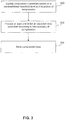
- FIG. 3 illustrates an overall flow diagram for reducing data storage requirements in a database system by these compression techniques.
- the process includes identifying at least one data candidate of fixed length data type in at least one row of database data for compression based upon a predetermined threshold level and a boundary of compression (block 300). At least one bit is provided within the at least one row for an identified data candidate according to the boundary of compression (block 302). The at least one row is then stored as compressed data in the database system (block 304).
- row level compression is performed by recognizing the possible waste of storage for fixed length data types.
- ASE has a full set of fixed length data types, such as “int”, “char”, “double” etc., that can be used to define data columns. In most cases, the data actually stored in a fixed length data column does not need the full length as defined.
- 4 bytes are used as a default size for the data type "int”. If the data to be stored is "100”, not all 4 bytes are needed, since 1 byte covers up to 2 8 (256), making the other 3 bytes redundant.
- the row compression of the present invention includes storing the value of certain fixed length data types as needed and in variable length format.
- Some fixed length data types are not included in the row compression, since there would not be any benefit from the compression.
- the data type "tinyint" uses only 1 byte. So, columns having such data types are not changed to variable length and remain as fixed length column format. In this way, those fixed data type column lengths that do not fall below a predetermined threshold level (e.g., 4 bytes) are considered for row compression.
- offset data is used to indicate the variable length column.
- Prior approaches allow a fixed number of bytes, such as 2 bytes, for the column offset.
- further space savings is achieved by compressing the offset data in conjunction with changing more fixed length column to variable length.
- a bitmap is used to map out all the lengths for the variable length columns in a row. By using an offset bitmap, several bits indicate the length of the column after compression, where the number of bits used depends upon the maximum length of the column.
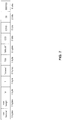
- FIG. 4 illustrates the row format 400 before compression for this table.
- the row format generally has a row header, followed by fixed length columns, followed by a row length, followed by variable length columns, and ending with an offset table.
- row based compression of a table can be used and normally occurs as a result of explicit specification in the create table statement.
- column 1 is specified as one byte of "char" data type
- column 3 is specified as "tinyint” data type (also one byte by default), so these columns do not meet the predefined threshold and therefore are not considered candidates for row level compression.
- Columns 2 and 4 are recognized to be potentially compressible, since they are of fixed data type with 50 bytes specified (column 2) and a default 4 bytes specified (column 4). Accordingly, column 2 and column 4 are changed to variable length columns as part of the row boundary compression.
- an altered row format 500 for the example table when compressed in accordance with an embodiment of the present invention includes positioning the row length after the row header and ahead of the fixed length columns that are not compressed.
- the compressed columns follow the uncompressed fixed columns, which are followed by the variable length columns that may also be compressed.
- the end columns of the row format provide the "offset bitmap" which indicates the length of each of the compressed columns and variable length columns.
- the maximum length of the column 2 is 50, so 6 bits are used in the offset bitmap to indicate the column length (2 6 ⁇ 50).
- 2 bits are used to indicate its length (2 2 ⁇ 4).
- bit padding comprises 3 bits.
- FIG. 6 an input row 600 of sample data is illustrated with the uncompressed row format for the example of FIG. 4 . As shown, with the sample data, the total length is 71 bytes.
- FIG. 7 illustrates the row 700 after utilizing the compression approach of the present invention on the same input data. As shown, the total length of the compressed row is 23 bytes.
- the lack of a NULL value in the fixed length columns is recognized such that a '0' value can be used for a column with a length of 1, a '1' value can be used to represent a column with length 2, and so on.
- some fixed length columns are not compressed since they do not have any redundancy (tinyint or bit, for example), while other fixed length columns (int or char for example) can be compressed to reduce redundancy.
- a number of bits are used in a compressed offset table to indicate the column's length following its compression.
- variable length columns can be compressed in a similar manner.
- the offset table utilized provides storage savings since instead of using a set 2 bytes to indicate the offset of the variable length column, several bits in an offset bitmap indicate the column lengths after compression
- data compression techniques address potential data redundancy on a page boundary with minimization of the data redundancy in columns in one or more rows on a given page.
- page compression common 'byte' patterns at the beginning of all columns on the page are sought, where 'byte' patterns do not distinguish according to the column data type but instead all columns are treated as a byte string.
- a page dictionary is created and included in the page right after the existing page header, as shown in the page representation 800 of FIG. 8 .
- a page dictionary is created by extracting single column duplicates as dictionary entries and utilizing a symbol reference to the dictionary entry in the column data. In this manner, the single column extraction process looks for the common values in all the columns on that page.
- the process begins by extracting all the columns that exceed a predetermined length, such as 4 bytes, and are used as a page dictionary entry.
- a predetermined length such as 4 bytes
- two arrays are used to indicate all of the extracted columns, e.g., BYTE*colptr[] (column pointer) and unit16 collen[] (column length).
- a sorting of the extracted columns follows, such as using a quick sort, where the pointers, rather than the original columns, are exchanged for better performance.
- the columns indicated by the array colptr[] are sorted on byte order, i.e., col1(aaa) appears ahead of col2(aab).
- a cost evaluation function is utilized to choose the optimal dictionary value, taking into account the row format of DOL table. In the example case, "aaaaa" will become the page dictionary entry. This process is repeated to generate all of the page dictionary entries.
- the page dictionary entries are reordered to compress the column as much as possible. For example, suppose two page dictionary entries have been generated, entry[0](aaaa) and entry[1](aaaaaaaaaa). Because of the byte order property of the colptr[], the entry[1] will be generated after entry[0]. However, if a column col(aaaaaaaaaaaaaaaaaaaa) is the input of the compression function, then it is preferred to compress it as much as possible, which would result from use of entry[1]. Accordingly, the reordering places entry[1] ahead of entry[0] in order to allow for more space savings.
- the row in the page is compressed where the redundant portion of the row has only one copy in the page (becomes the page dictionary entry), and its old position will be substituted by a symbol with much smaller size.
- One bit/column in the page dictionary chart suitably indicates whether the corresponding column has the page dictionary entry. If the specified column does have the page dictionary information, the first byte of the specified column is the index of the page dictionary row. If the row length after page-dictionary-compression exceeds the original row length, the original row is saved instead of the page-compressed one.
- the row format includes a row header, followed by a row length, followed by a page dictionary chart, followed by fixed length columns, then variable length columns, and ending with an offset table.
- the first byte in col2 suitably indicates the page dictionary index with one bit in the status of the row header used to indicate whether the row has page dictionary information. Using one bit in the page dictionary chart can indicate whether the corresponding column has the page dictionary information. If the row doesn't have page dictionary information, the row has the ordinary row format ( FIG. 4 ).
- this extraction process based on single columns has few steps to reduce the overhead caused by the page dictionary compression of the row and to reduce the CPU cost of the creation of the page dictionary.
- compression on a page boundary is improved by extracting multiple column duplicates as well.
- the column's length is short (i.e., does not exceed a predetermined threshold), there will not be any page dictionary entry generated from it. But in actual practice, there are often many duplicates in the page from such a short column.
- TPCC Transaction Processing Performance Council C
- FIG. 10 illustrates a standard row format 1000 for the table.
- FIG. 11 illustrates sample data 1100 for this table.
- ol_d_id there are many duplicates in the columns ol_d_id, ol_w_id, ol_supply_w_id, and ol_quantity. These columns have the same properties: their length is short and they are fixed length columns. So, in the process of the single column page dictionary generation, there will not be any entries from these columns, because they are less than the predetermined threshold for single page column extraction, e.g., 4 bytes. But, as can be seen from the example data, the information in these columns is redundant. So, another page compression method is introduced in an embodiment of the present invention to compress the page further.
- the values are the same across the rows in each of columns ol_d_id, ol_w_id, ol_supply_w_id and ol_quantity.
- the lengths of these columns are all below the defined threshold.
- these values are extracted out to format the page index row.
- the page index is formed as one row with all the page index entries and preferably is placed behind the page dictionary row.
- FIG. 12 shows the page layout 1200 by using both page dictionary compression and page index compression.
- one bit in the row status is used to indicate that this row can be page-index compressed, and the corresponding columns will not occupy any storage.
- the values of the four columns ol_d_id, ol_w_id, ol_supply_w_id and ol_quantity in one specified row are all the same with the page index row, one status bit is set in the row header to indicate that this row can be page-index compressed, and none of the contents of the four columns are stored in this row. For such a row, the row format would be changed to the row format 1300 shown in FIG. 13 .
- FIG. 14 illustrates a resultant row format 1400 when applying both techniques in accordance with an embodiment of the invention.
- both techniques When to apply both techniques is dependent upon the needs of a particular system and indicated upon table creation, as is well appreciated by those skilled in the art. It can be recognized that when most operations on a table are SELECT operations, the combined, comprehensive compression realizes even better gain in space savings along with performance by reducing I/O and by reducing the metadata resources used to manage the data.
- the compression techniques of the present invention can improve distributed database (or clusters) performance by reducing network data traffic. Also, memory utilization is improved by a reduced data footprint along with a reduction in the amount of data to log.
Description
- The present invention relates generally to database systems and, more particularly, to data compression in database systems.
- Computers are very powerful tools for storing and providing access to vast amounts of information. Relational databases are a common mechanism for storing information on computer systems while providing easy access to users. A typical relational database is an organized collection of related information stored as "records" having "fields" of information. As an example, a database of employees may have a record for each employee where each record contains fields designating specifics about the employee, such as name, home address, salary, and the like.
- Between the actual physical database itself (i.e., the data actually stored on a storage device) and the users of the system, a relational database management system or RDBMS is typically provided as a software cushion or layer. In essence, the RDBMS shields the database user from knowing or even caring about the underlying hardware-level details. Typically, all requests from users for access to the data are processed by the RDBMS. For example, information may be added or removed from data files, information retrieved from or updated in such files, and so forth, all without user knowledge of the underlying system implementation. In this manner, the RDBMS provides users with a conceptual view of the database that is removed from the hardware level. The general construction and operation of database management systems is well known in the art. See e.g., Date, C., "An Introduction to Database Systems, Seventh Edition", Part I (especially Chapters 1-4), Addison Wesley, 2000.
- Efficient data access is one of the properties provided by a database management system. A key challenge faced by relational database systems is the ever-growing database size. With increasing use of digital devices and ease of data flow on ubiquitous networks, the data explosion has accelerated in recent years. As regular database and table size has grown tremendously in recent years, data compression becomes increasing important even for databases. While row level compression and page level compression for databases have been introduced, a need remains for improved compression techniques to overcome deficiencies in these approaches without introducing new overhead. The present invention addresses this need.
-
US 2006/0212625 discloses procedures for compression/migration of data. A data relay module migrates data from a logical volume in compression units comprising a set of a given number of data blocks. The data relay module stores the post-compression data into the migration destination logical volume and a correspondence relationship between the pre-migration and post-migration block sets is stored into a control table. -
US2008/0071818 discloses a technique for compressing data in a relational database. - Aspects of the invention are set out in the independent claims. Certain preferred features are set out in the dependent claims.
- Disclosed embodiments include methods, systems, and computer program products for reducing data storage requirements in a database system. An embodiment includes identifying at least one data candidate of fixed length data type in at least one row of database data for compression based upon a predetermined threshold level and a boundary of compression, providing at least one bit within the at least one row for an identified data candidate according to the boundary of compression, and storing the at least one row as compressed data in the database system. For compression based on a row boundary, the identified data candidates for compression include fixed length columns having lengths that do not fall below the predetermined threshold level in a row of data and the at least one bit comprises a bitmap for a length of the identified data candidates following compression. For compression based on a page boundary, the identified data candidates for compression include redundant byte string data in a page of data, the redundant byte string data including matching data across columns having lengths that do not exceed the predetermined threshold level.
- Further features and advantages of the invention, as well as the structure and operation of various embodiments of the invention, are described in detail below with reference to the accompanying drawings. It is noted that the invention is not limited to the specific embodiments described herein. Such embodiments are presented herein for illustrative purposes only. Additional embodiments will be apparent to persons skilled in the relevant art(s) based on the teachings contained herein.
- The accompanying drawings, which are incorporated herein and form a part of the specification, illustrate the present invention and, together with the description, further serve to explain the principles of the invention and to enable a person skilled in the relevant art to make and use the invention.
-
FIG. 1 illustrates a general block diagram of a computer system in which software-implemented processes of the present invention may be embodied -
FIG. 2 illustrates the general structure of a client/server database system 200 suitable for implementing the present invention. -
FIG. 3 illustrates an overall flow diagram for reducing data storage requirements in a database system in accordance with an embodiment of the present invention. -
FIG. 4 depicts a row format before compression for an example table. -
FIG. 5 depicts an altered row format for the example table when compressed in accordance with an embodiment of the present invention -
FIG. 6 depicts an input row of sample data with the uncompressed row format for the example ofFIG. 4 . -
FIG. 7 depicts a row resulting after utilizing an embodiment of the compression approach of the present invention on the same input data used forFIG. 6 . -
FIG. 8 depicts a page representation that includes a page dictionary in accordance with an embodiment of the present invention. -
FIG. 9 depicts a row format using the page dictionary results based on example table data after the page dictionary compression in accordance with an embodiment of the present invention. -
FIG. 10 depicts a standard row format for a sample table. -
FIG. 11 depicts sample data for the sample table ofFIG. 10 . -
FIG. 12 depicts a page representation resulting when using both page dictionary compression and page index compression in accordance with an embodiment of the present invention. -
FIG. 13 depicts a row format for the sample data ofFIG. 11 for a row with page index compression in accordance with an embodiment of the present invention. -
FIG. 14 depicts a row format when applying compression techniques on both a page and row boundary in accordance with an embodiment of the present invention. - The present invention will now be described with reference to the accompanying drawings. In the drawings, generally, like reference numbers indicate identical or functionally similar elements. Additionally, generally, the left-most digit(s) of a reference number identifies the drawing in which the reference number first appears.
- The following detailed description of the present invention refers to the accompanying drawings that illustrate exemplary embodiments consistent with this invention. Other embodiments are possible, and modifications can be made to the embodiments within the scope of the invention. Therefore, the detailed description is not meant to limit the invention. Rather, the scope of the invention is defined by the appended claims.
- It would be apparent to one of skill in the art that the present invention, as described below, can be implemented in many different embodiments of software, hardware, firmware, and/or the entities illustrated in the figures. Any actual software code with the specialized control of hardware to implement the present invention is not limiting of the present invention. Thus, the operational behavior of the present invention will be described with the understanding that modifications and variations of the embodiments are possible, given the level of detail presented herein.
- Referring to the figures, exemplary embodiments of the invention will now be described. The following description will focus on the presently preferred embodiment of the present invention, which is implemented in desktop and/or server software (e.g., driver, application, or the like) operating in an Internet-connected environment running under an operating system, such as the Microsoft Windows operating system. The present invention, however, is not limited to any one particular application or any particular environment. Instead, those skilled in the art will find that the system and methods of the present invention may be advantageously embodied on a variety of different platforms, including Linux, Solaris, UNIX, IBM AIX, and the like. Therefore, the description of the exemplary embodiments that follows is for purposes of illustration and not limitation. The exemplary embodiments are primarily described with reference to block diagrams or flowcharts. As to the flowcharts, each block within the flowcharts represents both a method act and an apparatus element for performing the method act. Depending upon the implementation, the corresponding apparatus element may be configured in hardware, software, firmware, or combinations thereof.
- The present invention may be implemented on a conventional or general-purpose computer system, such as an IBM-compatible personal computer (PC) or server computer.
FIG. 1 illustrates a general block diagram of a computer system (e.g., an IBM-compatible system) in which software-implemented processes of the present invention may be embodied. As shown,system 100 comprises a central processing unit(s) (CPU) or processor(s) 101 coupled to a random-access memory (RAM) 102, a read-only memory (ROM) 103, akeyboard 106, aprinter 107, apointing device 108, a display orvideo adapter 104 connected to adisplay device 105, a removable (mass) storage device 115 (e.g., floppy disk, CD-ROM, CD-R, CD-RW, DVD, or the like), a fixed (mass) storage device 116 (e.g., hard disk), a communication (COMM) port(s) or interface(s) 110, amodem 112, and a network interface card (NIC) or controller 111 (e.g., Ethernet). Although not shown separately, a real time system clock is included with thesystem 100, in a conventional manner. -
CPU 101 comprises any suitable processor, such as a processor of the Intel Pentium family of microprocessors, for implementing the present invention. TheCPU 101 communicates with other components of the system via a bi-directional system bus (including any necessary input/output (I/O) controller circuitry and other "glue" logic). The bus, which includes address lines for addressing system memory, provides data transfer between and among the various components, as is well understood in the art. Random-access memory 102 serves as the working memory for theCPU 101. In a typical configuration, RAM of multiple megabytes or gigabytes is employed. More or less memory may be used without departing from the scope of the present invention. The read-only memory (ROM) 103 contains the basic input/output system code (BIOS)--a set of low-level routines in the ROM that application programs and the operating systems can use to interact with the hardware, including reading characters from the keyboard, outputting characters to printers, and so forth. -
Mass storage devices FIG. 1 , fixedstorage 116 stores a body of program and data for directing operation of the computer system, including an operating system, user application programs, driver and other support files, as well as other data files of all sorts. Typically, the fixedstorage 116 serves as the main hard disk for the system. - In basic operation, program logic (including that which implements methodology of the present invention described below) is loaded from the
removable storage 115 or fixedstorage 116 into the main (RAM)memory 102, for execution by theCPU 101. During operation of the program logic, thesystem 100 accepts user input from akeyboard 106 andpointing device 108, as well as speech-based input from a voice recognition system (not shown). Thekeyboard 106 permits selection of application programs, entry of keyboard-based input or data, and selection and manipulation of individual data objects displayed on the screen ordisplay device 105. Likewise, thepointing device 108, such as a mouse, track ball, pen device, or the like, permits selection and manipulation of objects on the display device. In this manner, these input devices support manual user input for any process running on the system. - The
computer system 100 displays text and/or graphic images and other data on thedisplay device 105. Thevideo adapter 104, which is interposed between thedisplay device 105 and the system's bus, drives thedisplay device 105. Thevideo adapter 104, which includes video memory accessible to theCPU 101, provides circuitry that converts pixel data stored in the video memory to a raster signal suitable for use by a cathode ray tube (CRT) raster or liquid crystal display (LCD) monitor. A hard copy of the displayed information, or other information within thesystem 100, may be obtained from theprinter 107, or other output device.Printer 107 may include, for instance, a HP LaserJet printer (available from Hewlett Packard of Palo Alto, Calif.), for creating hard copy images of output of the system. - The system itself communicates with other devices (e.g., other computers) via the network interface card (NIC) 111 connected to a network (e.g., Ethernet network, Bluetooth wireless network, or the like), and/or modem 112 (e.g., 56K baud, ISDN, DSL, or cable modem), examples of which are available from 3Com of Santa Clara, Calif. The
system 100 may also communicate with local occasionally-connected devices (e.g., serial cable-linked devices) via the communication (COMM)interface 110, which may include a RS-232 serial port, a Universal Serial Bus (USB) interface, or the like. Devices that will be commonly connected locally to theinterface 110 include laptop computers, handheld organizers, digital cameras, and the like. - IBM-compatible personal computers and server computers are available from a variety of vendors. Representative vendors include Dell Computers of Round Rock, Tex., Hewlett-Packard of Palo Alto, Calif., and IBM of Armonk, N.Y. Other suitable computers include Apple-compatible computers (e.g., Macintosh), which are available from Apple Computer of Cupertino, Calif., and Sun Solaris workstations, which are available from Sun Microsystems of Mountain View, Calif.
- A software system is typically provided for controlling the operation of the
computer system 100. The software system, which is usually stored in system memory (RAM) 102 and on fixed storage (e.g., hard disk) 116, includes a kernel or operating system (OS) which manages low-level aspects of computer operation, including managing execution of processes, memory allocation, file input and output (I/O), and device I/O. The OS can be provided by a conventional operating system, Microsoft Windows NT, Microsoft Windows 2000, Microsoft Windows XP, or Microsoft Windows Vista (Microsoft Corporation of Redmond, Wash.) or an alternative operating system, such as the previously mentioned operating systems. Typically, the OS operates in conjunction with device drivers (e.g., "Winsock" driver--Windows' implementation of a TCP/IP stack) and the system BIOS microcode (i.e., ROM-based microcode), particularly when interfacing with peripheral devices. One or more application(s), such as client application software or "programs" (i.e., set of processor-executable instructions), may also be provided for execution by thecomputer system 100. The application(s) or other software intended for use on the computer system may be "loaded" intomemory 102 from fixedstorage 116 or may be downloaded from an Internet location (e.g., Web server). A graphical user interface (GUI) is generally provided for receiving user commands and data in a graphical (e.g., "point-and-click") fashion. These inputs, in turn, may be acted upon by the computer system in accordance with instructions from OS and/or application(s). The graphical user interface also serves to display the results of operation from the OS and application(s). - While the present invention may operate within a single (standalone) computer (e.g.,
system 100 ofFIG. 1 ), the present invention is preferably embodied in a multi-user computer system, such as a client/server system.FIG. 2 illustrates the general structure of a client/server database system 200 suitable for implementing the present invention. (Specific modifications to thesystem 200 for implementing methodologies of the present invention are described in subsequent sections below.) As shown, thesystem 200 comprises one or more client(s) 210 connected to aserver 230 via anetwork 220. Specifically, the client(s) 210 comprise one or morestandalone terminals 211 connected to adatabase server system 240 using a conventional network. In an exemplary embodiment, theterminals 211 may themselves comprise a plurality of standalone workstations, dumb terminals, or the like, or comprise personal computers (PCs) such as the above-describedsystem 100. Typically, such units would operate under a client operating system, such as a Microsoft® Windows client operating system (e.g., Microsoft® Windows 95/98, Windows 2000, or Windows XP). - The
database server system 240, which comprises Sybase® Adaptive Server® Enterprise (ASE) (available from Sybase, Inc. of Dublin, Calif.) in an exemplary embodiment, generally operates as an independent process (i.e., independently of the clients), running under a server operating system such as Microsoft® Windows NT, Windows 2000, or Windows XP (all from Microsoft Corporation of Redmond, Wash.), UNIX (Novell), Solaris (Sun), or Linux (Red Hat). Thenetwork 220 may be any one of a number of conventional network systems, including a Local Area Network (LAN) or Wide Area Network (WAN), as is known in the art (e.g., using Ethernet, IBM Token Ring, or the like). Thenetwork 220 includes functionality for packaging client calls in the well-known Structured Query Language (SQL) together with any parameter information into a format (of one or more packets) suitable for transmission to thedatabase server system 240. The described computer hardware and software are presented for purposes of illustrating the basic underlying desktop and server computer components that may be employed for implementing the present invention. For purposes of discussion, the following description will present examples in which it will be assumed that there exist multiple server instances (e.g., database server nodes) in a cluster that communicate with one or more "clients" (e.g., personal computers or mobile devices). The present invention, however, is not limited to any particular environment or device configuration. Instead, the present invention may be implemented in any type of system architecture or processing environment capable of supporting the methodologies of the present invention presented in detail below. - Client/server environments, database servers, and networks are well documented in the technical, trade, and patent literature. In operation, the client(s) 210 store data in, or retrieve data from, one or more database tables 250, as shown at
FIG. 2 . Data in a relational database is stored as a series of tables, also called relations. Typically resident on theserver 230, each table itself comprises one or more "rows" or "records" (tuples) (e.g.,row 255 as shown atFIG. 2 ). A typical database will contain many tables, each of which stores information about a particular type of entity. A table in a typical relational database may contain anywhere from a few rows to millions of rows. A row is divided into fields or columns; each field represents one particular attribute of the given row. A row corresponding to an employee record, for example, may include information about the employee's ID Number, Last Name and First Initial, Position, Date Hired, Social Security Number (SSN), and Salary. Each of these categories, in turn, represents a database field. In the foregoing employee table, for example, Position is one field, Date Hired is another, and so on. With this format, tables are easy for users to understand and use. Moreover, the flexibility of tables permits a user to define relationships between various items of data, as needed. Thus, a typical record includes several categories of information about an individual person, place, or thing. Each row in a table is uniquely identified by a record ID (RID), which can be used as a pointer to a given row. - Most relational databases implement a variant of the Structured Query Language (SQL), which is a language allowing users and administrators to create, manipulate, and access data stored in the database. The syntax of SQL is well documented; see, e.g., the above-mentioned "An Introduction to Database Systems". SQL statements maybe divided into two categories: data manipulation language (DML), used to read and write data; and data definition language (DDL), used to describe data and maintain the database. DML statements are also called queries. In operation, for example, the
clients 210 issue one or more SQL commands to theserver 230. SQL commands may specify, for instance, a query for retrieving particular data (i.e., data records meeting the query condition) from the database table(s) 250. In addition to retrieving the data from database server table(s) 250, theclients 210 also have the ability to issue commands to insert new rows of data records into the table(s), or to update and/or delete existing records in the table(s). - SQL statements or simply "queries" must be parsed to determine an access plan (also known as "execution plan" or "query plan") to satisfy a given query. In operation, the SQL statements received from the client(s) 210 (via network 220) are processed by the
engine 260 of thedatabase server system 240. Theengine 260 itself comprises aparser 261, anormalizer 263, acompiler 265, anexecution unit 269, and anaccess method 270. Specifically, the SQL statements are passed to theparser 261 which employs conventional parsing methodology (e.g., recursive descent parsing). The parsed query is then normalized by thenormalizer 263. Normalization includes, for example, the elimination of redundant data. Additionally, thenormalizer 263 performs error checking, such as confirming that table names and column names which appear in the query are valid (e.g., are available and belong together). Finally, thenormalizer 263 can also look-up any referential integrity constraints which exist and add those to the query. - After normalization, the query is passed to the
compiler 265, which includes aquery optimizer 266 and acode generator 267. Thequery optimizer 266 performs a cost-based analysis for formulating a query execution plan that is reasonably close to an optimal plan. Thecode generator 267 translates the query execution plan selected by thequery optimizer 266 into executable form for execution by theexecution unit 269 using theaccess methods 270. - All data in a typical relational database system is stored in pages on a secondary storage device, usually a hard disk. Typically, these pages may range in size from 1 Kb to 32 Kb, with the most common page sizes being 2 Kb and 4 Kb. All input/output operations (I/O) against secondary storage are done in page-sized units--that is, the entire page is read/written at once. Pages are also allocated for one purpose at a time: a database page may be used to store table data or used for virtual memory, but it will not be used for both. The memory in which pages that have been read from disk reside is called the cache or buffer pool.
- I/O to and from the disk tends to be the most costly operation in executing a query. This is due to the latency associated with the physical media, in comparison with the relatively low latency of main memory (e.g., RAM). Query performance can thus be increased by reducing the number of I/O operations that must be completed. This can be done by using data structures and algorithms that maximize the use of pages that are known to reside in the cache. Alternatively, it can be done by being more selective about what pages are loaded into the cache in the first place. An additional consideration with respect to I/O is whether it is sequential or random. Due to the construction of hard disks, sequential I/O is much faster then random access I/O. Data structures and algorithms encouraging the use of sequential I/O can realize greater performance.
- The present invention improves I/O performance for more efficient query processing and database operation by utilizing compression techniques that reduce data storage requirements. As will be described in further detail herein below, embodiments of the present invention address both row level boundary compression and page level boundary compression.
FIG. 3 illustrates an overall flow diagram for reducing data storage requirements in a database system by these compression techniques. The process includes identifying at least one data candidate of fixed length data type in at least one row of database data for compression based upon a predetermined threshold level and a boundary of compression (block 300). At least one bit is provided within the at least one row for an identified data candidate according to the boundary of compression (block 302). The at least one row is then stored as compressed data in the database system (block 304). - In performing data compression at a row boundary, row level compression is performed by recognizing the possible waste of storage for fixed length data types. For example, ASE has a full set of fixed length data types, such as "int", "char", "double" etc., that can be used to define data columns. In most cases, the data actually stored in a fixed length data column does not need the full length as defined. By way of example, in ASE, 4 bytes are used as a default size for the data type "int". If the data to be stored is "100", not all 4 bytes are needed, since 1 byte covers up to 28 (256), making the other 3 bytes redundant. Instead of wasting the space resulting from such a redundancy scenario, the row compression of the present invention includes storing the value of certain fixed length data types as needed and in variable length format. Some fixed length data types are not included in the row compression, since there would not be any benefit from the compression. For example, the data type "tinyint" uses only 1 byte. So, columns having such data types are not changed to variable length and remain as fixed length column format. In this way, those fixed data type column lengths that do not fall below a predetermined threshold level (e.g., 4 bytes) are considered for row compression.
- In compressing row data by changing certain fixed length data types to variable length, offset data is used to indicate the variable length column. Prior approaches allow a fixed number of bytes, such as 2 bytes, for the column offset. In accordance with the present invention, further space savings is achieved by compressing the offset data in conjunction with changing more fixed length column to variable length. Instead of using a fixed number of bytes for each column offset, a bitmap is used to map out all the lengths for the variable length columns in a row. By using an offset bitmap, several bits indicate the length of the column after compression, where the number of bits used depends upon the maximum length of the column.
- By way of example, suppose a table is created as indicated below:
- create table t1 (coll char(1),
- col2 char(50),
- col3 tinyint,
- col4 int,
- col5 varchar(20)) lock datapages
-
FIG. 4 illustrates the row format 400 before compression for this table. As can be recognized, the row format generally has a row header, followed by fixed length columns, followed by a row length, followed by variable length columns, and ending with an offset table. In order to reduce the storage requirements for the row, row based compression of a table can be used and normally occurs as a result of explicit specification in the create table statement. To compress the row in accordance with an embodiment of the invention, it is seen thatcolumn 1 is specified as one byte of "char" data type andcolumn 3 is specified as "tinyint" data type (also one byte by default), so these columns do not meet the predefined threshold and therefore are not considered candidates for row level compression.Columns default 4 bytes specified (column 4). Accordingly,column 2 andcolumn 4 are changed to variable length columns as part of the row boundary compression. - As illustrated in
FIG. 5 , an altered row format 500 for the example table when compressed in accordance with an embodiment of the present invention includes positioning the row length after the row header and ahead of the fixed length columns that are not compressed. The compressed columns follow the uncompressed fixed columns, which are followed by the variable length columns that may also be compressed. The end columns of the row format provide the "offset bitmap" which indicates the length of each of the compressed columns and variable length columns. For example, the maximum length of thecolumn 2 is 50, so 6 bits are used in the offset bitmap to indicate the column length (26 ≥ 50). Forcolumn - In
FIG. 6 , an input row 600 of sample data is illustrated with the uncompressed row format for the example ofFIG. 4 . As shown, with the sample data, the total length is 71 bytes.FIG. 7 illustrates the row 700 after utilizing the compression approach of the present invention on the same input data. As shown, the total length of the compressed row is 23 bytes. - The reduced storage needed results from row level compressing. Referring to
column 2, based on the example input data, the value is 5 'a' followed by 45 blanks. After compression, the compressed value ofcolumn 2 is the 5 'a' data and the length of the compressedcolumn 2 is 5. For column 4 (int), the value is 100, so only one byte is needed to represent this value. Based on the data for column 5 (varchar(20)), only five bytes are needed to store the value ofcolumn 5 and the trailing blanks are truncated. - In providing an offset bitmap to represent the compressed lengths, preferably the lack of a NULL value in the fixed length columns is recognized such that a '0' value can be used for a column with a length of 1, a '1' value can be used to represent a column with
length 2, and so on. Accordingly, for the length of 5 for thecompressed column 2 in the example, the bit string of 000100(0 × 25 + 0 × 24 + 0 × 23 + 1 × 22 + 0 × 21 + 0 × 20 = 4), capably represents the length of 5. Forcolumn 4, the bit string 00(0×21 + 0 × 20 = 0) capably represents the length of 1. - For
column 5, since it is a variable data type, it could have a NULL value and thus the '0' value in the bit string cannot be used in the same manner as for the fixed data type columns being compressed. Accordingly, for thecompressed column 5, the bit string 00101(0 × 24 + 0 × 23 + 1 × 22 + 0 × 21 + 1 × 2° = 5) is used to represent its length and the bit string 00000 would be used to represent a NULL value. - As has been described, some fixed length columns are not compressed since they do not have any redundancy (tinyint or bit, for example), while other fixed length columns (int or char for example) can be compressed to reduce redundancy. A number of bits are used in a compressed offset table to indicate the column's length following its compression. Further, variable length columns can be compressed in a similar manner. In addition, the offset table utilized provides storage savings since instead of using a
set 2 bytes to indicate the offset of the variable length column, several bits in an offset bitmap indicate the column lengths after compression - Further, when access to a compressed row is sought, such as through index or table scan, the row will be decompressed and the decompressed row will be transferred to other modules that need this row in the database system. In so doing, the row stays in uncompressed state in the memory unless it is needed. Significant disk IO savings are realized, since there are more rows in one page. Log space savings are realized also, since only the compressed information needs to be stored in the log, as is well appreciated by those skilled in the art.
- In accordance with an embodiment of the present invention, data compression techniques address potential data redundancy on a page boundary with minimization of the data redundancy in columns in one or more rows on a given page. Under page compression, common 'byte' patterns at the beginning of all columns on the page are sought, where 'byte' patterns do not distinguish according to the column data type but instead all columns are treated as a byte string. Based on data redundancy found, a page dictionary is created and included in the page right after the existing page header, as shown in the
page representation 800 ofFIG. 8 . Commonly, a page dictionary is created by extracting single column duplicates as dictionary entries and utilizing a symbol reference to the dictionary entry in the column data. In this manner, the single column extraction process looks for the common values in all the columns on that page. - The process begins by extracting all the columns that exceed a predetermined length, such as 4 bytes, and are used as a page dictionary entry. Preferably, two arrays are used to indicate all of the extracted columns, e.g., BYTE*colptr[] (column pointer) and unit16 collen[] (column length). A sorting of the extracted columns follows, such as using a quick sort, where the pointers, rather than the original columns, are exchanged for better performance. Through the sorting, the columns indicated by the array colptr[] are sorted on byte order, i.e., col1(aaa) appears ahead of col2(aab).
- Next, an array offset[] is utilized to sort the column indicated by the colptr[] to indicate the length of the common prefix byte string. For example, starting from the first column indicated by the colptr[0], suppose colptr[0](aaaaa), colptr[1](aaaaa), colptr[2](aaaac), colptr[3](aaaad), colptr[4](abc).... Accordingly, based on the common prefix byte string data, the resulting offset[] values are offset[0]=5, offset[1]=5, offset[2]=4, offset[3]=4, offset[4]=1. The values in this array are descending and generation of the array is ended if offset[i] < 4.
- A cost evaluation function is utilized to choose the optimal dictionary value, taking into account the row format of DOL table. In the example case, "aaaaa" will become the page dictionary entry. This process is repeated to generate all of the page dictionary entries.
- Once the page dictionary entries are generated, they are reordered to compress the column as much as possible. For example, suppose two page dictionary entries have been generated, entry[0](aaaa) and entry[1](aaaaaaaaaa). Because of the byte order property of the colptr[], the entry[1] will be generated after entry[0]. However, if a column col(aaaaaaaaaaaaa) is the input of the compression function, then it is preferred to compress it as much as possible, which would result from use of entry[1]. Accordingly, the reordering places entry[1] ahead of entry[0] in order to allow for more space savings.
- Based on these entries, the row in the page is compressed where the redundant portion of the row has only one copy in the page (becomes the page dictionary entry), and its old position will be substituted by a symbol with much smaller size. One bit/column in the page dictionary chart suitably indicates whether the corresponding column has the page dictionary entry. If the specified column does have the page dictionary information, the first byte of the specified column is the index of the page dictionary row. If the row length after page-dictionary-compression exceeds the original row length, the original row is saved instead of the page-compressed one.
- By way of example, using the same example table data as in
FIG. 3 , after the page dictionary compression, suppose the col2(char(50)) has the page dictionary information, so that the row format using the page dictionary results in theformat 900 as shown inFIG. 9 . As can be recognized, the row format includes a row header, followed by a row length, followed by a page dictionary chart, followed by fixed length columns, then variable length columns, and ending with an offset table. The first byte in col2 suitably indicates the page dictionary index with one bit in the status of the row header used to indicate whether the row has page dictionary information. Using one bit in the page dictionary chart can indicate whether the corresponding column has the page dictionary information. If the row doesn't have page dictionary information, the row has the ordinary row format (FIG. 4 ). - As described, this extraction process based on single columns has few steps to reduce the overhead caused by the page dictionary compression of the row and to reduce the CPU cost of the creation of the page dictionary.
- In accordance with the present invention, compression on a page boundary is improved by extracting multiple column duplicates as well. As described above, if the column's length is short (i.e., does not exceed a predetermined threshold), there will not be any page dictionary entry generated from it. But in actual practice, there are often many duplicates in the page from such a short column. By way of example the following provides a table from the TPCC (Transaction Processing Performance Council C) benchmark.
 create table order_line (
    ol_o_id     int,
    ol_d_id     tinyint,
    ol_w_id     smallint,
    ol_number    tinyint,
    ol_i_id     int,
    ol_supply_w_id     smallint,
    ol_delivery_d     datetime,
    ol_quantity     smallint,
    ol_amount     float,
    ol_dist_info     char(24)
    ) lock datapages
 go
Claims (9)
- A method for compressing data in a relational database table stored in a relational database system, the table comprising one or more rows, each row divided into columns, the method comprising:identifying (300), in at least one row of the table having a first row format (400), a data column defined with a fixed length data type for compression, wherein the identifying step comprises selecting the data column for compression based on whether the length of the fixed-length data column meets a predetermined column length threshold; andstoring (304) the at least one row containing the identified data column as compressed data in the database system using a second row format (500) different from the first row format, the storing comprising:storing the value of the data column having the fixed length data type in a variable length format; andincluding a bitmap in the row, comprising bits indicating the length of the data column after compression, where the number of bits used depends upon the maximum length of the fixed-length data column.
- The method of claim 1, wherein data columns identified for compression comprise fixed length columns having lengths that do not fall below the predetermined threshold in a row of data for compression based on a row boundary.
- The method of claim 1, wherein data columns identified for compression further comprise redundant byte string data in a page of data for compression based on a page boundary.
- The method of claim 3, wherein the redundant byte string data comprises matching data across columns having lengths that do not exceed the predetermined threshold.
- The method of claim 4, comprising including at least one bit in a row status to indicate compression of the identified data column.
- The method of claim 5, further comprising extracting the redundant byte string data into a page index.
- The method of claim 6, wherein the page index supplements a page dictionary for the page of data.
- A system comprising means for carrying out the method of any of claims 1 - 7.
- A computer program product comprising a computer usable medium having computer program logic recorded thereon for enabling a processor to reduce data storage requirements in a database system, the computer program logic arranged to perform the method of any of claims 1 - 7 when executed by a suitably arranged computer.
Applications Claiming Priority (2)
| Application Number | Priority Date | Filing Date | Title |
|---|---|---|---|
| US12/488,022 US8706727B2 (en) | 2009-06-19 | 2009-06-19 | Data compression for reducing storage requirements in a database system |
| PCT/US2010/038994 WO2010148201A2 (en) | 2009-06-19 | 2010-06-17 | Data compression for reducing storage requirements in a database system |
Publications (3)
| Publication Number | Publication Date |
|---|---|
| EP2443564A2 EP2443564A2 (en) | 2012-04-25 |
| EP2443564A4 EP2443564A4 (en) | 2016-05-11 |
| EP2443564B1 true EP2443564B1 (en) | 2020-06-10 |
Family
ID=43355154
Family Applications (1)
| Application Number | Title | Priority Date | Filing Date |
|---|---|---|---|
| EP10790192.8A Active EP2443564B1 (en) | 2009-06-19 | 2010-06-17 | Data compression for reducing storage requirements in a database system |
Country Status (4)
| Country | Link |
|---|---|
| US (1) | US8706727B2 (en) |
| EP (1) | EP2443564B1 (en) |
| CN (1) | CN102804168B (en) |
| WO (1) | WO2010148201A2 (en) |
Cited By (1)
| Publication number | Priority date | Publication date | Assignee | Title |
|---|---|---|---|---|
| WO2022216289A1 (en) * | 2021-04-08 | 2022-10-13 | Syncadd Systems, Inc. | Efficiently accessing, storing and transmitting data elements |
Families Citing this family (33)
| Publication number | Priority date | Publication date | Assignee | Title |
|---|---|---|---|---|
| US8806112B2 (en) * | 2011-07-14 | 2014-08-12 | Lsi Corporation | Meta data handling within a flash media controller |
| US8560508B2 (en) * | 2011-07-22 | 2013-10-15 | International Business Machines Corporation | Real-time compression of tabular data |
| US9053121B2 (en) | 2013-01-10 | 2015-06-09 | International Business Machines Corporation | Real-time identification of data candidates for classification based compression |
| US9792350B2 (en) | 2013-01-10 | 2017-10-17 | International Business Machines Corporation | Real-time classification of data into data compression domains |
| US9564918B2 (en) | 2013-01-10 | 2017-02-07 | International Business Machines Corporation | Real-time reduction of CPU overhead for data compression |
| US9876507B2 (en) | 2013-02-22 | 2018-01-23 | Sap Se | Semantic compression of structured data |
| US10841405B1 (en) * | 2013-03-15 | 2020-11-17 | Teradata Us, Inc. | Data compression of table rows |
| US9235564B2 (en) * | 2013-07-19 | 2016-01-12 | International Business Machines Corporation | Offloading projection of fixed and variable length database columns |
| US10048075B2 (en) | 2013-07-19 | 2018-08-14 | Sap Se | Trajectory data compression |
| US9489409B2 (en) | 2013-10-17 | 2016-11-08 | Sybase, Inc. | Rollover strategies in a N-bit dictionary compressed column store |
| US9977801B2 (en) * | 2013-11-21 | 2018-05-22 | Sap Se | Paged column dictionary |
| US10235377B2 (en) | 2013-12-23 | 2019-03-19 | Sap Se | Adaptive dictionary compression/decompression for column-store databases |
| CN104768079B (en) * | 2014-01-03 | 2018-10-02 | 腾讯科技(深圳)有限公司 | Multimedia resource distribution method, apparatus and system |
| US10936595B2 (en) * | 2014-04-03 | 2021-03-02 | Sybase, Inc. | Deferring and/or eliminating decompressing database data |
| US9916338B2 (en) | 2015-04-24 | 2018-03-13 | International Business Machines Corporation | Managing data records |
| US9552384B2 (en) | 2015-06-19 | 2017-01-24 | HGST Netherlands B.V. | Apparatus and method for single pass entropy detection on data transfer |
| US10152389B2 (en) | 2015-06-19 | 2018-12-11 | Western Digital Technologies, Inc. | Apparatus and method for inline compression and deduplication |
| US11403318B2 (en) | 2015-10-01 | 2022-08-02 | Futurewei Technologies, Inc. | Apparatus and method for managing storage of a primary database and a replica database |
| US10108667B2 (en) | 2016-03-07 | 2018-10-23 | International Business Machines Corporation | Query plan optimization for large payload columns |
| US10817540B2 (en) * | 2016-09-02 | 2020-10-27 | Snowflake Inc. | Incremental clustering maintenance of a table |
| US10671587B2 (en) | 2017-03-31 | 2020-06-02 | International Business Machines Corporation | Reduced fixed length sort of variable length columns |
| CN109753227B (en) * | 2017-11-08 | 2021-11-23 | 北京嘀嘀无限科技发展有限公司 | Storage method, device, mobile terminal, server and readable storage medium |
| CN108920573A (en) * | 2018-06-22 | 2018-11-30 | 北京奇艺世纪科技有限公司 | A kind of data buffer storage processing method, device and terminal device |
| US10860608B2 (en) * | 2018-10-25 | 2020-12-08 | EMC IP Holding Company LLC | Any point in time replication to the cloud |
| US11143545B2 (en) * | 2019-02-12 | 2021-10-12 | Computational Systems, Inc. | Thinning of scalar vibration data |
| US11620056B2 (en) | 2019-06-28 | 2023-04-04 | EMC IP Holding Company LLC | Snapshots for any point in time replication |
| CN111427885B (en) * | 2020-03-03 | 2023-06-09 | 中科驭数(北京)科技有限公司 | Database management method and device based on lookup table |
| CN111767280A (en) * | 2020-04-17 | 2020-10-13 | 北京沃东天骏信息技术有限公司 | Data processing method, device and storage medium |
| CN112230032A (en) * | 2020-08-03 | 2021-01-15 | 青岛鼎信通讯股份有限公司 | Electric energy meter data compression and decompression method |
| US11917072B2 (en) * | 2020-12-03 | 2024-02-27 | International Business Machines Corporation | Implementing opportunistic authentication of encrypted data |
| CN113613289B (en) * | 2021-08-02 | 2024-03-22 | 重庆优米工业自动化设备有限公司 | Bluetooth data transmission method, system and communication equipment |
| CN113821475A (en) * | 2021-11-22 | 2021-12-21 | 湖北芯擎科技有限公司 | Data transmission method and device, electronic equipment and storage medium |
| US20240012799A1 (en) * | 2022-07-05 | 2024-01-11 | Sap Se | Compression service using fpga compression |
Citations (1)
| Publication number | Priority date | Publication date | Assignee | Title |
|---|---|---|---|---|
| US20080071818A1 (en) * | 2006-09-18 | 2008-03-20 | Infobright Inc. | Method and system for data compression in a relational database |
Family Cites Families (16)
| Publication number | Priority date | Publication date | Assignee | Title |
|---|---|---|---|---|
| US5467087A (en) * | 1992-12-18 | 1995-11-14 | Apple Computer, Inc. | High speed lossless data compression system |
| US5678043A (en) * | 1994-09-23 | 1997-10-14 | The Regents Of The University Of Michigan | Data compression and encryption system and method representing records as differences between sorted domain ordinals that represent field values |
| CN1282937C (en) * | 1995-07-31 | 2006-11-01 | 富士通株式会社 | Medium processor and medium processing method |
| CN100535889C (en) * | 1997-10-21 | 2009-09-02 | 富士通株式会社 | File processing method, data processing device and storing medium |
| US6661845B1 (en) | 1999-01-14 | 2003-12-09 | Vianix, Lc | Data compression system and method |
| JP3736185B2 (en) | 1999-03-16 | 2006-01-18 | コニカミノルタビジネステクノロジーズ株式会社 | Image processing device |
| US7028039B2 (en) * | 2001-01-18 | 2006-04-11 | Hewlett-Packard Development Company, L.P. | System and method for storing connectivity information in a web database |
| US6757648B2 (en) * | 2001-06-28 | 2004-06-29 | Microsoft Corporation | Techniques for quantization of spectral data in transcoding |
| JP2005045452A (en) | 2003-07-25 | 2005-02-17 | Konica Minolta Business Technologies Inc | Apparatus and program for image processing, and image composing method |
| US8126900B1 (en) * | 2004-02-03 | 2012-02-28 | Teradata Us, Inc. | Transforming a data type of a column in a table |
| JP4615337B2 (en) * | 2005-03-16 | 2011-01-19 | 株式会社日立製作所 | Storage system |
| CN1851691A (en) * | 2005-04-22 | 2006-10-25 | 北京九州软件有限公司 | Database back-up data compression and search method |
| US20080133562A1 (en) * | 2006-12-05 | 2008-06-05 | Chi Ping Bess Cheong | Coding compressible variable length database fields |
| US8150850B2 (en) * | 2008-01-07 | 2012-04-03 | Akiban Technologies, Inc. | Multiple dimensioned database architecture |
| US7975071B2 (en) * | 2008-01-18 | 2011-07-05 | Microsoft Corporation | Content compression in networks |
| US8261201B2 (en) * | 2008-02-22 | 2012-09-04 | Microsoft Corporation | Spectrum bar control |
-
2009
- 2009-06-19 US US12/488,022 patent/US8706727B2/en active Active
-
2010
- 2010-06-17 EP EP10790192.8A patent/EP2443564B1/en active Active
- 2010-06-17 WO PCT/US2010/038994 patent/WO2010148201A2/en active Application Filing
- 2010-06-17 CN CN201080027310.2A patent/CN102804168B/en active Active
Patent Citations (1)
| Publication number | Priority date | Publication date | Assignee | Title |
|---|---|---|---|---|
| US20080071818A1 (en) * | 2006-09-18 | 2008-03-20 | Infobright Inc. | Method and system for data compression in a relational database |
Cited By (1)
| Publication number | Priority date | Publication date | Assignee | Title |
|---|---|---|---|---|
| WO2022216289A1 (en) * | 2021-04-08 | 2022-10-13 | Syncadd Systems, Inc. | Efficiently accessing, storing and transmitting data elements |
Also Published As
| Publication number | Publication date |
|---|---|
| WO2010148201A2 (en) | 2010-12-23 |
| US8706727B2 (en) | 2014-04-22 |
| WO2010148201A3 (en) | 2011-03-31 |
| CN102804168A (en) | 2012-11-28 |
| EP2443564A4 (en) | 2016-05-11 |
| EP2443564A2 (en) | 2012-04-25 |
| US20100325094A1 (en) | 2010-12-23 |
| CN102804168B (en) | 2016-03-09 |
Similar Documents
| Publication | Publication Date | Title |
|---|---|---|
| EP2443564B1 (en) | Data compression for reducing storage requirements in a database system | |
| US7293040B2 (en) | System and methodology for database migration between platforms | |
| EP3602351B1 (en) | Apparatus and method for distributed query processing utilizing dynamically generated in-memory term maps | |
| US20100257181A1 (en) | Dynamic Hash Table for Efficient Data Access In A Relational Database System | |
| US7346633B2 (en) | System providing methodology for replication subscription resolution | |
| US8458218B2 (en) | Incremental data transfer in a database management system | |
| US6598051B1 (en) | Web page connectivity server | |
| US8352458B2 (en) | Techniques for transforming and loading data into a fact table in a data warehouse | |
| US5918225A (en) | SQL-based database system with improved indexing methodology | |
| US5794229A (en) | Database system with methodology for storing a database table by vertically partitioning all columns of the table | |
| US6694323B2 (en) | System and methodology for providing compact B-Tree | |
| US9916313B2 (en) | Mapping of extensible datasets to relational database schemas | |
| US6778985B1 (en) | Implementing descending indexes with a descend function | |
| EP0336586A2 (en) | Data storage, retrieval and transmission in computer systems | |
| US20120323971A1 (en) | Optimizing data storage and access of an in-memory database | |
| US6366902B1 (en) | Using an epoch number to optimize access with rowid columns and direct row access | |
| JP2004530216A (en) | Integration of tablespaces of different block sizes | |
| US6343286B1 (en) | Efficient technique to defer large object access with intermediate results | |
| US20210209088A1 (en) | Method and system to support indexing in row-group columnar storage | |
| US20110289112A1 (en) | Database system, database management method, database structure, and storage medium | |
| US10810174B2 (en) | Database management system, database server, and database management method | |
| US9600578B1 (en) | Inverted index and inverted list process for storing and retrieving information | |
| US6535895B2 (en) | Technique to avoid processing well clustered LOB's during reorganization of a LOB table space | |
| US20120078860A1 (en) | Algorithmic compression via user-defined functions | |
| US9129001B2 (en) | Character data compression for reducing storage requirements in a database system |
Legal Events
| Date | Code | Title | Description |
|---|---|---|---|
| PUAI | Public reference made under article 153(3) epc to a published international application that has entered the european phase |
Free format text: ORIGINAL CODE: 0009012 |
|
| 17P | Request for examination filed |
Effective date: 20111209 |
|
| AK | Designated contracting states |
Kind code of ref document: A2 Designated state(s): AL AT BE BG CH CY CZ DE DK EE ES FI FR GB GR HR HU IE IS IT LI LT LU LV MC MK MT NL NO PL PT RO SE SI SK SM TR |
|
| DAX | Request for extension of the european patent (deleted) | ||
| A4 | Supplementary search report drawn up and despatched |
Effective date: 20160407 |
|
| RIC1 | Information provided on ipc code assigned before grant |
Ipc: G06F 17/30 20060101ALI20160401BHEP Ipc: G06F 9/06 20060101ALI20160401BHEP Ipc: G06F 17/00 20060101AFI20160401BHEP Ipc: G06F 17/20 20060101ALI20160401BHEP |
|
| STAA | Information on the status of an ep patent application or granted ep patent |
Free format text: STATUS: EXAMINATION IS IN PROGRESS |
|
| 17Q | First examination report despatched |
Effective date: 20170130 |
|
| REG | Reference to a national code |
Ref country code: DE Ref legal event code: R079 Ref document number: 602010064588 Country of ref document: DE Free format text: PREVIOUS MAIN CLASS: G06F0017000000 Ipc: G06F0016220000 |
|
| GRAP | Despatch of communication of intention to grant a patent |
Free format text: ORIGINAL CODE: EPIDOSNIGR1 |
|
| STAA | Information on the status of an ep patent application or granted ep patent |
Free format text: STATUS: GRANT OF PATENT IS INTENDED |
|
| RIC1 | Information provided on ipc code assigned before grant |
Ipc: G06F 16/22 20190101AFI20191210BHEP |
|
| INTG | Intention to grant announced |
Effective date: 20200102 |
|
| GRAS | Grant fee paid |
Free format text: ORIGINAL CODE: EPIDOSNIGR3 |
|
| GRAA | (expected) grant |
Free format text: ORIGINAL CODE: 0009210 |
|
| STAA | Information on the status of an ep patent application or granted ep patent |
Free format text: STATUS: THE PATENT HAS BEEN GRANTED |
|
| AK | Designated contracting states |
Kind code of ref document: B1 Designated state(s): AL AT BE BG CH CY CZ DE DK EE ES FI FR GB GR HR HU IE IS IT LI LT LU LV MC MK MT NL NO PL PT RO SE SI SK SM TR |
|
| REG | Reference to a national code |
Ref country code: GB Ref legal event code: FG4D |
|
| REG | Reference to a national code |
Ref country code: CH Ref legal event code: EP Ref country code: AT Ref legal event code: REF Ref document number: 1279739 Country of ref document: AT Kind code of ref document: T Effective date: 20200615 |
|
| REG | Reference to a national code |
Ref country code: DE Ref legal event code: R096 Ref document number: 602010064588 Country of ref document: DE |
|
| REG | Reference to a national code |
Ref country code: IE Ref legal event code: FG4D |
|
| REG | Reference to a national code |
Ref country code: LT Ref legal event code: MG4D |
|
| PG25 | Lapsed in a contracting state [announced via postgrant information from national office to epo] |
Ref country code: NO Free format text: LAPSE BECAUSE OF FAILURE TO SUBMIT A TRANSLATION OF THE DESCRIPTION OR TO PAY THE FEE WITHIN THE PRESCRIBED TIME-LIMIT Effective date: 20200910 Ref country code: GR Free format text: LAPSE BECAUSE OF FAILURE TO SUBMIT A TRANSLATION OF THE DESCRIPTION OR TO PAY THE FEE WITHIN THE PRESCRIBED TIME-LIMIT Effective date: 20200911 Ref country code: FI Free format text: LAPSE BECAUSE OF FAILURE TO SUBMIT A TRANSLATION OF THE DESCRIPTION OR TO PAY THE FEE WITHIN THE PRESCRIBED TIME-LIMIT Effective date: 20200610 Ref country code: SE Free format text: LAPSE BECAUSE OF FAILURE TO SUBMIT A TRANSLATION OF THE DESCRIPTION OR TO PAY THE FEE WITHIN THE PRESCRIBED TIME-LIMIT Effective date: 20200610 Ref country code: LT Free format text: LAPSE BECAUSE OF FAILURE TO SUBMIT A TRANSLATION OF THE DESCRIPTION OR TO PAY THE FEE WITHIN THE PRESCRIBED TIME-LIMIT Effective date: 20200610 |
|
| REG | Reference to a national code |
Ref country code: NL Ref legal event code: MP Effective date: 20200610 |
|
| PG25 | Lapsed in a contracting state [announced via postgrant information from national office to epo] |
Ref country code: BG Free format text: LAPSE BECAUSE OF FAILURE TO SUBMIT A TRANSLATION OF THE DESCRIPTION OR TO PAY THE FEE WITHIN THE PRESCRIBED TIME-LIMIT Effective date: 20200910 Ref country code: LV Free format text: LAPSE BECAUSE OF FAILURE TO SUBMIT A TRANSLATION OF THE DESCRIPTION OR TO PAY THE FEE WITHIN THE PRESCRIBED TIME-LIMIT Effective date: 20200610 Ref country code: HR Free format text: LAPSE BECAUSE OF FAILURE TO SUBMIT A TRANSLATION OF THE DESCRIPTION OR TO PAY THE FEE WITHIN THE PRESCRIBED TIME-LIMIT Effective date: 20200610 |
|
| REG | Reference to a national code |
Ref country code: AT Ref legal event code: MK05 Ref document number: 1279739 Country of ref document: AT Kind code of ref document: T Effective date: 20200610 |
|
| PG25 | Lapsed in a contracting state [announced via postgrant information from national office to epo] |
Ref country code: AL Free format text: LAPSE BECAUSE OF FAILURE TO SUBMIT A TRANSLATION OF THE DESCRIPTION OR TO PAY THE FEE WITHIN THE PRESCRIBED TIME-LIMIT Effective date: 20200610 Ref country code: NL Free format text: LAPSE BECAUSE OF FAILURE TO SUBMIT A TRANSLATION OF THE DESCRIPTION OR TO PAY THE FEE WITHIN THE PRESCRIBED TIME-LIMIT Effective date: 20200610 |
|
| PG25 | Lapsed in a contracting state [announced via postgrant information from national office to epo] |
Ref country code: AT Free format text: LAPSE BECAUSE OF FAILURE TO SUBMIT A TRANSLATION OF THE DESCRIPTION OR TO PAY THE FEE WITHIN THE PRESCRIBED TIME-LIMIT Effective date: 20200610 Ref country code: SM Free format text: LAPSE BECAUSE OF FAILURE TO SUBMIT A TRANSLATION OF THE DESCRIPTION OR TO PAY THE FEE WITHIN THE PRESCRIBED TIME-LIMIT Effective date: 20200610 Ref country code: EE Free format text: LAPSE BECAUSE OF FAILURE TO SUBMIT A TRANSLATION OF THE DESCRIPTION OR TO PAY THE FEE WITHIN THE PRESCRIBED TIME-LIMIT Effective date: 20200610 Ref country code: IT Free format text: LAPSE BECAUSE OF FAILURE TO SUBMIT A TRANSLATION OF THE DESCRIPTION OR TO PAY THE FEE WITHIN THE PRESCRIBED TIME-LIMIT Effective date: 20200610 Ref country code: CZ Free format text: LAPSE BECAUSE OF FAILURE TO SUBMIT A TRANSLATION OF THE DESCRIPTION OR TO PAY THE FEE WITHIN THE PRESCRIBED TIME-LIMIT Effective date: 20200610 Ref country code: RO Free format text: LAPSE BECAUSE OF FAILURE TO SUBMIT A TRANSLATION OF THE DESCRIPTION OR TO PAY THE FEE WITHIN THE PRESCRIBED TIME-LIMIT Effective date: 20200610 Ref country code: PT Free format text: LAPSE BECAUSE OF FAILURE TO SUBMIT A TRANSLATION OF THE DESCRIPTION OR TO PAY THE FEE WITHIN THE PRESCRIBED TIME-LIMIT Effective date: 20201012 Ref country code: ES Free format text: LAPSE BECAUSE OF FAILURE TO SUBMIT A TRANSLATION OF THE DESCRIPTION OR TO PAY THE FEE WITHIN THE PRESCRIBED TIME-LIMIT Effective date: 20200610 |
|
| REG | Reference to a national code |
Ref country code: CH Ref legal event code: PL |
|
| PG25 | Lapsed in a contracting state [announced via postgrant information from national office to epo] |
Ref country code: PL Free format text: LAPSE BECAUSE OF FAILURE TO SUBMIT A TRANSLATION OF THE DESCRIPTION OR TO PAY THE FEE WITHIN THE PRESCRIBED TIME-LIMIT Effective date: 20200610 Ref country code: SK Free format text: LAPSE BECAUSE OF FAILURE TO SUBMIT A TRANSLATION OF THE DESCRIPTION OR TO PAY THE FEE WITHIN THE PRESCRIBED TIME-LIMIT Effective date: 20200610 Ref country code: IS Free format text: LAPSE BECAUSE OF FAILURE TO SUBMIT A TRANSLATION OF THE DESCRIPTION OR TO PAY THE FEE WITHIN THE PRESCRIBED TIME-LIMIT Effective date: 20201010 |
|
| REG | Reference to a national code |
Ref country code: DE Ref legal event code: R097 Ref document number: 602010064588 Country of ref document: DE |
|
| PG25 | Lapsed in a contracting state [announced via postgrant information from national office to epo] |
Ref country code: MC Free format text: LAPSE BECAUSE OF FAILURE TO SUBMIT A TRANSLATION OF THE DESCRIPTION OR TO PAY THE FEE WITHIN THE PRESCRIBED TIME-LIMIT Effective date: 20200610 Ref country code: LU Free format text: LAPSE BECAUSE OF NON-PAYMENT OF DUE FEES Effective date: 20200617 |
|
| PLBE | No opposition filed within time limit |
Free format text: ORIGINAL CODE: 0009261 |
|
| STAA | Information on the status of an ep patent application or granted ep patent |
Free format text: STATUS: NO OPPOSITION FILED WITHIN TIME LIMIT |
|
| REG | Reference to a national code |
Ref country code: BE Ref legal event code: MM Effective date: 20200630 |
|
| PG25 | Lapsed in a contracting state [announced via postgrant information from national office to epo] |
Ref country code: DK Free format text: LAPSE BECAUSE OF FAILURE TO SUBMIT A TRANSLATION OF THE DESCRIPTION OR TO PAY THE FEE WITHIN THE PRESCRIBED TIME-LIMIT Effective date: 20200610 Ref country code: CH Free format text: LAPSE BECAUSE OF NON-PAYMENT OF DUE FEES Effective date: 20200630 Ref country code: IE Free format text: LAPSE BECAUSE OF NON-PAYMENT OF DUE FEES Effective date: 20200617 Ref country code: LI Free format text: LAPSE BECAUSE OF NON-PAYMENT OF DUE FEES Effective date: 20200630 |
|
| 26N | No opposition filed |
Effective date: 20210311 |
|
| PG25 | Lapsed in a contracting state [announced via postgrant information from national office to epo] |
Ref country code: SI Free format text: LAPSE BECAUSE OF FAILURE TO SUBMIT A TRANSLATION OF THE DESCRIPTION OR TO PAY THE FEE WITHIN THE PRESCRIBED TIME-LIMIT Effective date: 20200610 Ref country code: BE Free format text: LAPSE BECAUSE OF NON-PAYMENT OF DUE FEES Effective date: 20200630 |
|
| PG25 | Lapsed in a contracting state [announced via postgrant information from national office to epo] |
Ref country code: TR Free format text: LAPSE BECAUSE OF FAILURE TO SUBMIT A TRANSLATION OF THE DESCRIPTION OR TO PAY THE FEE WITHIN THE PRESCRIBED TIME-LIMIT Effective date: 20200610 Ref country code: MT Free format text: LAPSE BECAUSE OF FAILURE TO SUBMIT A TRANSLATION OF THE DESCRIPTION OR TO PAY THE FEE WITHIN THE PRESCRIBED TIME-LIMIT Effective date: 20200610 Ref country code: CY Free format text: LAPSE BECAUSE OF FAILURE TO SUBMIT A TRANSLATION OF THE DESCRIPTION OR TO PAY THE FEE WITHIN THE PRESCRIBED TIME-LIMIT Effective date: 20200610 |
|
| PG25 | Lapsed in a contracting state [announced via postgrant information from national office to epo] |
Ref country code: MK Free format text: LAPSE BECAUSE OF FAILURE TO SUBMIT A TRANSLATION OF THE DESCRIPTION OR TO PAY THE FEE WITHIN THE PRESCRIBED TIME-LIMIT Effective date: 20200610 |
|
| PGFP | Annual fee paid to national office [announced via postgrant information from national office to epo] |
Ref country code: FR Payment date: 20230627 Year of fee payment: 14 Ref country code: DE Payment date: 20220914 Year of fee payment: 14 |
|
| PGFP | Annual fee paid to national office [announced via postgrant information from national office to epo] |
Ref country code: GB Payment date: 20230622 Year of fee payment: 14 |