EP2442177B1 - Backlight unit and liquid crystal display device - Google Patents
Backlight unit and liquid crystal display device Download PDFInfo
- Publication number
- EP2442177B1 EP2442177B1 EP11184693.7A EP11184693A EP2442177B1 EP 2442177 B1 EP2442177 B1 EP 2442177B1 EP 11184693 A EP11184693 A EP 11184693A EP 2442177 B1 EP2442177 B1 EP 2442177B1
- Authority
- EP
- European Patent Office
- Prior art keywords
- protrusions
- wall part
- frame
- inner frame
- protrusion
- Prior art date
- Legal status (The legal status is an assumption and is not a legal conclusion. Google has not performed a legal analysis and makes no representation as to the accuracy of the status listed.)
- Active
Links
- 239000004973 liquid crystal related substance Substances 0.000 title claims description 27
- 230000002093 peripheral effect Effects 0.000 claims description 10
- 238000006073 displacement reaction Methods 0.000 description 17
- 239000000758 substrate Substances 0.000 description 8
- 239000000463 material Substances 0.000 description 6
- 230000003287 optical effect Effects 0.000 description 4
- 239000002184 metal Substances 0.000 description 3
- 239000011347 resin Substances 0.000 description 3
- 229920005989 resin Polymers 0.000 description 3
- 230000001413 cellular effect Effects 0.000 description 2
- 230000000881 depressing effect Effects 0.000 description 2
- 238000000034 method Methods 0.000 description 2
- 238000012986 modification Methods 0.000 description 2
- 230000004048 modification Effects 0.000 description 2
- 239000007787 solid Substances 0.000 description 2
- 239000004925 Acrylic resin Substances 0.000 description 1
- 229920000178 Acrylic resin Polymers 0.000 description 1
- 239000002390 adhesive tape Substances 0.000 description 1
- 238000009792 diffusion process Methods 0.000 description 1
- 230000005489 elastic deformation Effects 0.000 description 1
- 239000011521 glass Substances 0.000 description 1
- 230000035699 permeability Effects 0.000 description 1
- 238000000926 separation method Methods 0.000 description 1
- 239000010409 thin film Substances 0.000 description 1
Images


Classifications
-
- G—PHYSICS
- G02—OPTICS
- G02F—OPTICAL DEVICES OR ARRANGEMENTS FOR THE CONTROL OF LIGHT BY MODIFICATION OF THE OPTICAL PROPERTIES OF THE MEDIA OF THE ELEMENTS INVOLVED THEREIN; NON-LINEAR OPTICS; FREQUENCY-CHANGING OF LIGHT; OPTICAL LOGIC ELEMENTS; OPTICAL ANALOGUE/DIGITAL CONVERTERS
- G02F1/00—Devices or arrangements for the control of the intensity, colour, phase, polarisation or direction of light arriving from an independent light source, e.g. switching, gating or modulating; Non-linear optics
- G02F1/01—Devices or arrangements for the control of the intensity, colour, phase, polarisation or direction of light arriving from an independent light source, e.g. switching, gating or modulating; Non-linear optics for the control of the intensity, phase, polarisation or colour
- G02F1/13—Devices or arrangements for the control of the intensity, colour, phase, polarisation or direction of light arriving from an independent light source, e.g. switching, gating or modulating; Non-linear optics for the control of the intensity, phase, polarisation or colour based on liquid crystals, e.g. single liquid crystal display cells
- G02F1/133—Constructional arrangements; Operation of liquid crystal cells; Circuit arrangements
- G02F1/1333—Constructional arrangements; Manufacturing methods
- G02F1/133308—Support structures for LCD panels, e.g. frames or bezels
-
- G—PHYSICS
- G02—OPTICS
- G02F—OPTICAL DEVICES OR ARRANGEMENTS FOR THE CONTROL OF LIGHT BY MODIFICATION OF THE OPTICAL PROPERTIES OF THE MEDIA OF THE ELEMENTS INVOLVED THEREIN; NON-LINEAR OPTICS; FREQUENCY-CHANGING OF LIGHT; OPTICAL LOGIC ELEMENTS; OPTICAL ANALOGUE/DIGITAL CONVERTERS
- G02F1/00—Devices or arrangements for the control of the intensity, colour, phase, polarisation or direction of light arriving from an independent light source, e.g. switching, gating or modulating; Non-linear optics
- G02F1/01—Devices or arrangements for the control of the intensity, colour, phase, polarisation or direction of light arriving from an independent light source, e.g. switching, gating or modulating; Non-linear optics for the control of the intensity, phase, polarisation or colour
- G02F1/13—Devices or arrangements for the control of the intensity, colour, phase, polarisation or direction of light arriving from an independent light source, e.g. switching, gating or modulating; Non-linear optics for the control of the intensity, phase, polarisation or colour based on liquid crystals, e.g. single liquid crystal display cells
- G02F1/133—Constructional arrangements; Operation of liquid crystal cells; Circuit arrangements
- G02F1/1333—Constructional arrangements; Manufacturing methods
-
- G—PHYSICS
- G02—OPTICS
- G02B—OPTICAL ELEMENTS, SYSTEMS OR APPARATUS
- G02B6/00—Light guides; Structural details of arrangements comprising light guides and other optical elements, e.g. couplings
- G02B6/0001—Light guides; Structural details of arrangements comprising light guides and other optical elements, e.g. couplings specially adapted for lighting devices or systems
- G02B6/0011—Light guides; Structural details of arrangements comprising light guides and other optical elements, e.g. couplings specially adapted for lighting devices or systems the light guides being planar or of plate-like form
- G02B6/0013—Means for improving the coupling-in of light from the light source into the light guide
- G02B6/0015—Means for improving the coupling-in of light from the light source into the light guide provided on the surface of the light guide or in the bulk of it
- G02B6/002—Means for improving the coupling-in of light from the light source into the light guide provided on the surface of the light guide or in the bulk of it by shaping at least a portion of the light guide, e.g. with collimating, focussing or diverging surfaces
-
- G—PHYSICS
- G02—OPTICS
- G02B—OPTICAL ELEMENTS, SYSTEMS OR APPARATUS
- G02B6/00—Light guides; Structural details of arrangements comprising light guides and other optical elements, e.g. couplings
- G02B6/0001—Light guides; Structural details of arrangements comprising light guides and other optical elements, e.g. couplings specially adapted for lighting devices or systems
- G02B6/0011—Light guides; Structural details of arrangements comprising light guides and other optical elements, e.g. couplings specially adapted for lighting devices or systems the light guides being planar or of plate-like form
- G02B6/0081—Mechanical or electrical aspects of the light guide and light source in the lighting device peculiar to the adaptation to planar light guides, e.g. concerning packaging
- G02B6/0083—Details of electrical connections of light sources to drivers, circuit boards, or the like
-
- G—PHYSICS
- G02—OPTICS
- G02B—OPTICAL ELEMENTS, SYSTEMS OR APPARATUS
- G02B6/00—Light guides; Structural details of arrangements comprising light guides and other optical elements, e.g. couplings
- G02B6/0001—Light guides; Structural details of arrangements comprising light guides and other optical elements, e.g. couplings specially adapted for lighting devices or systems
- G02B6/0011—Light guides; Structural details of arrangements comprising light guides and other optical elements, e.g. couplings specially adapted for lighting devices or systems the light guides being planar or of plate-like form
- G02B6/0081—Mechanical or electrical aspects of the light guide and light source in the lighting device peculiar to the adaptation to planar light guides, e.g. concerning packaging
- G02B6/0086—Positioning aspects
- G02B6/0088—Positioning aspects of the light guide or other optical sheets in the package
-
- G—PHYSICS
- G02—OPTICS
- G02F—OPTICAL DEVICES OR ARRANGEMENTS FOR THE CONTROL OF LIGHT BY MODIFICATION OF THE OPTICAL PROPERTIES OF THE MEDIA OF THE ELEMENTS INVOLVED THEREIN; NON-LINEAR OPTICS; FREQUENCY-CHANGING OF LIGHT; OPTICAL LOGIC ELEMENTS; OPTICAL ANALOGUE/DIGITAL CONVERTERS
- G02F1/00—Devices or arrangements for the control of the intensity, colour, phase, polarisation or direction of light arriving from an independent light source, e.g. switching, gating or modulating; Non-linear optics
- G02F1/01—Devices or arrangements for the control of the intensity, colour, phase, polarisation or direction of light arriving from an independent light source, e.g. switching, gating or modulating; Non-linear optics for the control of the intensity, phase, polarisation or colour
- G02F1/13—Devices or arrangements for the control of the intensity, colour, phase, polarisation or direction of light arriving from an independent light source, e.g. switching, gating or modulating; Non-linear optics for the control of the intensity, phase, polarisation or colour based on liquid crystals, e.g. single liquid crystal display cells
- G02F1/133—Constructional arrangements; Operation of liquid crystal cells; Circuit arrangements
- G02F1/1333—Constructional arrangements; Manufacturing methods
- G02F1/1335—Structural association of cells with optical devices, e.g. polarisers or reflectors
-
- G—PHYSICS
- G02—OPTICS
- G02F—OPTICAL DEVICES OR ARRANGEMENTS FOR THE CONTROL OF LIGHT BY MODIFICATION OF THE OPTICAL PROPERTIES OF THE MEDIA OF THE ELEMENTS INVOLVED THEREIN; NON-LINEAR OPTICS; FREQUENCY-CHANGING OF LIGHT; OPTICAL LOGIC ELEMENTS; OPTICAL ANALOGUE/DIGITAL CONVERTERS
- G02F1/00—Devices or arrangements for the control of the intensity, colour, phase, polarisation or direction of light arriving from an independent light source, e.g. switching, gating or modulating; Non-linear optics
- G02F1/01—Devices or arrangements for the control of the intensity, colour, phase, polarisation or direction of light arriving from an independent light source, e.g. switching, gating or modulating; Non-linear optics for the control of the intensity, phase, polarisation or colour
- G02F1/13—Devices or arrangements for the control of the intensity, colour, phase, polarisation or direction of light arriving from an independent light source, e.g. switching, gating or modulating; Non-linear optics for the control of the intensity, phase, polarisation or colour based on liquid crystals, e.g. single liquid crystal display cells
- G02F1/133—Constructional arrangements; Operation of liquid crystal cells; Circuit arrangements
- G02F1/1333—Constructional arrangements; Manufacturing methods
- G02F1/133308—Support structures for LCD panels, e.g. frames or bezels
- G02F1/133317—Intermediate frames, e.g. between backlight housing and front frame
-
- G—PHYSICS
- G02—OPTICS
- G02F—OPTICAL DEVICES OR ARRANGEMENTS FOR THE CONTROL OF LIGHT BY MODIFICATION OF THE OPTICAL PROPERTIES OF THE MEDIA OF THE ELEMENTS INVOLVED THEREIN; NON-LINEAR OPTICS; FREQUENCY-CHANGING OF LIGHT; OPTICAL LOGIC ELEMENTS; OPTICAL ANALOGUE/DIGITAL CONVERTERS
- G02F1/00—Devices or arrangements for the control of the intensity, colour, phase, polarisation or direction of light arriving from an independent light source, e.g. switching, gating or modulating; Non-linear optics
- G02F1/01—Devices or arrangements for the control of the intensity, colour, phase, polarisation or direction of light arriving from an independent light source, e.g. switching, gating or modulating; Non-linear optics for the control of the intensity, phase, polarisation or colour
- G02F1/13—Devices or arrangements for the control of the intensity, colour, phase, polarisation or direction of light arriving from an independent light source, e.g. switching, gating or modulating; Non-linear optics for the control of the intensity, phase, polarisation or colour based on liquid crystals, e.g. single liquid crystal display cells
- G02F1/133—Constructional arrangements; Operation of liquid crystal cells; Circuit arrangements
- G02F1/1333—Constructional arrangements; Manufacturing methods
- G02F1/133308—Support structures for LCD panels, e.g. frames or bezels
- G02F1/133322—Mechanical guidance or alignment of LCD panel support components
-
- G—PHYSICS
- G02—OPTICS
- G02F—OPTICAL DEVICES OR ARRANGEMENTS FOR THE CONTROL OF LIGHT BY MODIFICATION OF THE OPTICAL PROPERTIES OF THE MEDIA OF THE ELEMENTS INVOLVED THEREIN; NON-LINEAR OPTICS; FREQUENCY-CHANGING OF LIGHT; OPTICAL LOGIC ELEMENTS; OPTICAL ANALOGUE/DIGITAL CONVERTERS
- G02F2201/00—Constructional arrangements not provided for in groups G02F1/00 - G02F7/00
- G02F2201/46—Fixing elements
- G02F2201/465—Snap -fit
Definitions
- the present invention relates to a backlight unit and a liquid crystal display device, and more particularly to a technology that reduces relative positional displacements of members configuring the backlight unit.
- the backlight unit of a liquid crystal display device disclosed in JP 2009-192769A includes a light guide plate, and an inner frame molded from a resin that surrounds an outer circumstance of the light guide plate.
- the liquid crystal display panel arranged on the front side of the light guide plate is put inside the inner frame, and attached to the inner frame.
- the backlight unit disclosed in JP 2009-192769A also includes an outer frame inside which the inner frame is put.
- the outer frame is made of metal, and increases the strength of the liquid crystal display device.
- respective clearances are provided between the inner frame and the light guide plate, and between the inner frame and the outer frame.
- the clearances enable the light guide plate to be easily assembled with the inner frame, and also enable the inner frame to be easily assembled with the outer frame.
- US2006/0203519 and US2006/0290836 disclose also backlight structures in which a inner frame, having inner and outer protrusions formed thereon, holds a light guide through the inner protrusions and is fixed to an outer frame through the outer protrusions.
- the present invention has been made in view of the above problem, and an object of the present invention is to provide a backlight unit that can suppress relative positional displacements of members while ensuring the ease of assembling, and provide a liquid crystal display device including the backlight unit.
- a backlight unit for a liquid crystal display device includes a light guide plate, an inner frame that surrounds an outer periphery of the light guide plate, and an outer frame that surrounds an outer periphery of the inner frame.
- An inner periphery of the inner frame has an inner protrusion formed thereon and projecting toward the outer periphery of the light guide plate, and one of the outer periphery of the inner frame and an inner periphery of the outer frame has an outer protrusion formed thereon and projecting toward the other one.
- the inner protrusion and the outer protrusion are respectively located on opposite sides to each other across one side part of the inner frame, and arranged at a distance from each other in a longitudinal direction of the one side of the inner frame.
- the liquid crystal display device includes the backlight unit.
- the positional displacement of the light guide plate relative to the inner frame can be suppressed by the inner protrusion.
- the positional displacement of the inner frame relative to the outer frame can be suppressed by the outer protrusion.
- the inner protrusion and the outer protrusion are located at the distance from each other in the longitudinal direction of one side of the inner frame. For that reason, in assembling those three members together, the one side part of the inner frame can be recessed so that the ease of assembling can be ensured.
- the inner protrusion may be abutted against the outer periphery of the light guide plate. According to this aspect, the positional displacement of the light guide plate relative to the inner frame can be more surely suppressed.
- plural inner protrusions each functioning as the inner protrusion may be formed on the inner periphery of the inner frame. According to this aspect, a position of the light guide plate can be further stabilized within the inner frame.
- one of the outer periphery of the inner frame and the inner periphery of the outer frame may have plural outer protrusions each functioning the outer protrusion. According to this embodiment, a position of the inner frame can be further stabilized within the outer frame.
- the one of the outer periphery of the inner frame and the inner periphery of the outer frame may have a second outer protrusion formed thereon and projecting toward the other one, and the second outer protrusion may be located outside the opposite side part to the one side part of the inner frame. According to this aspect, the positional displacement of the inner frame relative to the outer frame can be further effectively suppressed.
- the opposite side part of the inner frame may have a second inner protrusion formed thereon and projecting toward the outer periphery of the light guide plate. According to this aspect, the positional displacement of the light guide plate relative to the inner frame can be further effectively suppressed.
- the second inner protrusion and the second outer protrusion may be located symmetrically about the opposite side part to the one side part of the inner frame.
- the second inner protrusion can prevent a portion of the inner frame where the second outer protrusion is formed (or a portion against which the second outer protrusion is abutted) from being recessed. For that reason, the inner frame is hardly come off from the outer frame.
- the outer protrusion may be engaged with the other one of the outer periphery of the inner frame and the inner periphery of the outer frame. According to this aspect, the inner frame can be prevented from being separated from the outer frame.
- the other one of the outer periphery of the inner frame and the inner periphery of the outer frame may have a hole formed thereon into which the outer protrusion is fitted.
- the separation of the inner frame from the outer frame can be further effectively suppressed.
- a clearance between the outer periphery of the inner frame and the inner periphery of the outer frame can be reduced.
- the inner frame can be fitted into the outer frame by depressing a portion of the inner frame where the outer protrusion is formed (or a portion against which the outer protrusion is abutted), and the ease of assembling can be ensured.
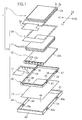
- FIG. 1 is an exploded perspective view of a liquid crystal display device 1 having a backlight unit 10 according to the embodiment of the present invention.
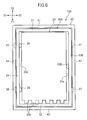
- FIG. 2 is a plan view of the backlight unit 10.
- FIG. 2 illustrates a light guide plate 20, an inner frame 30, and an outer frame 40 configuring the backlight unit 10.
- FIG. 3 is a cross-sectional view of the backlight unit 10 taken along a line III-III illustrated in FIG. 2 .
- FIG. 4 is an enlarged view of a main portion of FIG. 2 in which a first inner protrusion 35 and a first outer protrusion 37 formed on the inner frame 30 are illustrated.
- a direction along which a liquid crystal display panel 2 and the backlight unit 10 face each other is a vertical direction (up-down direction). Also, in FIG. 1 , it is assumed that a direction indicated by X1-X2 is a lateral direction (right-left direction), and a direction indicated by Y1-Y2 is a longitudinal direction (front-rear direction).
- the liquid crystal display device 1 includes the liquid crystal display panel 2 and the backlight unit 10 that illuminates the liquid crystal display panel 2 on the back side thereof.
- the liquid crystal display device 1 is a small display device mounted in mobile devices such as cellular phones, digital cameras, or PDAs (personal data assistances).
- the liquid crystal display panel 2 includes a pair of substrates 2a and 2b (glass substrates) having a light transparency. Liquid crystal is put between those substrates 2a and 2b.
- the substrate 2a had thin film transistors, electrodes, wirings and the like each formed thereon, and the substrate 2b has color filters formed thereon.
- the substrate 2a has a flexible printed circuit board 2e attached thereto on which an integrated circuit for driving the transistors, and the like are mounted.
- the flexible printed circuit board 2e is attached to a front edge of the substrate 2a.
- Polarizing plates 2c and 2d are attached to a front side and a back side of the substrates 2a and 2b, respectively (refer to FIG. 3 ).
- the backlight unit 10 includes a flexible printed circuit board 12, the light guide plate 20, plural optical sheets 11, and a reflection sheet 13. Also, the backlight unit 10 includes the inner frame 30 and the outer frame 40.
- Plural light sources for example, LEDs (light emitting diodes) 12b are mounted on the circuit board 12.
- the light sources 12b are arranged on a back side of the circuit board 12.
- the circuit board 12 is arranged so that the light sources 12b face a front portion 20c of an outer periphery (surface corresponding to the thickness of the light guide plate 20) of the light guide plate 20.
- the circuit board 12 is attached to a front edge of the light guide plate 20.
- protrusions 20b are formed on the front portion 20c of the outer periphery, and the circuit board 12 is attached onto upper surfaces of the protrusions 20b.
- a mounting structure of the circuit board 12 onto the light guide plate 20, and the position of the light sources 12b are not limited to the configuration described above, but may be appropriately changed.
- the light sources 12b may be mounted on the circuit board 2e attached to the liquid crystal display panel 2.
- the circuit board 2e is bent so that the light sources 12b face the outer periphery of the light guide plate 20.
- the light guide plate 20 is a substantially rectangular plate.
- the light guide plate 20 is made of a material (for example, acrylic resin) having a light permeability and a light diffuseness. For that reason, a light from the light sources 12b is diffused over an overall area of the light guide plate 20 while being diffusely reflected within the light guide plate 20, whereby the light guide plate 20 emits light from the surface thereof. That is, the light guide plate 20 substantially uniformly emits the light from the overall surface thereof.
- the plural optical sheets 11 are layered on the light guide plate 20.
- the optical sheets 11 include, for example, a diffusion sheet and a prism sheet.
- the liquid crystal display panel 2 is arranged above the optical sheets 11 (refer to FIG. 3 ).
- the reflection sheet 13 is arranged on a back surface (lower surface side) of the light guide plate 20. An outer peripheral part of the reflection sheet 13 is attached to the back surface of the inner frame 30.
- the inner frame 30 surrounds the outer periphery of the light guide plate 20.
- the inner frame 30 is rectangular, and includes an upper wall part 31, a lower wall part 32, a right wall part 33, and a left wall part 34 (refer to FIG. 2 ).
- Those wall parts 31, 32, 33, and 34 are each formed into an elongate bar with rectangle in cross section (cross section taken along a surface orthogonal to a longitudinal direction thereof), and are coupled to each other to form the rectangular inner frame 30.
- the inner frame 30 is molded integrally from resin.
- the inner frame 30 can be elastically deformed so that the part thereof is recessed as described later.
- the material of the inner frame 30 is not always limited to resin if the material allows such elastic deformation.
- the outer peripheral part of the liquid crystal display panel 2 is disposed on the inner frame 30, and thereby the liquid crystal display panel 2 is supported by the inner frame 30.
- a double-faced adhesive tape 14 is disposed on the upper surface (upper surfaces of the respective wall parts 31, 32, 33, and 34) of the inner frame 30.
- the tape 14 is shaped into a rectangle frame having a size corresponding to the inner frame 30 (refer to FIG. 1 ).
- the outer peripheral part of the liquid crystal display panel 2 is attached to the upper surface of the inner frame 30 through the tape 14.
- the outer frame 40 is so formed as to surround the outer periphery of the inner frame 30.
- the outer frame 40 is formed in a box shape open upward as illustrated in FIG. 1 or 3 , and stores the inner frame 30 and the light guide plate 20 therein.
- the outer frame 40 includes a rectangular bottom plate part 45.
- the light guide plate 20 and the inner frame 30 are arranged on the bottom plate part 45.
- the outer frame 40 includes a frame-shaped outer peripheral wall that stands on the edge of the bottom plate part 45 and surrounds the outer periphery of the inner frame 30.
- the outer peripheral wall is rectangular as a whole, and includes an upper wall part 41, a lower wall part 42, a right wall part 43, and a left wall part 44 as four sides thereof.
- the outer frame 40 is made of metal, and ensures the rigidity of the backlight unit 10. Also, when the backlight unit 10 is mounted in a device such as a cellular phone, the outer frame 40 is fixed to a housing of the device.
- the material of the backlight unit 10 is not always limited to metal if the material can ensure the rigidity of the backlight unit 10.
- the inner periphery (surface facing the outer periphery of the light guide plate 20) of the inner frame 30 has plural protrusions 35 and 36 formed thereon and projecting inwardly toward side surfaces 20a in the outer periphery of the light guide plate 20.
- Those protrusions 35 and 36 are molded integrally with the inner frame 30.
- the respective protrusions 35 and 36 are formed on two sides (two wall parts) of the inner frame 30 which are located opposite to each other.
- the plural (two in FIG. 2 ) protrusions 35 (hereinafter referred to as "first inner protrusions") are formed on the right wall part 33. Those two protrusions 35 are located at a distance from each other in a longitudinal direction (in this example, the longitudinal direction (the direction of Y1-Y2)) of the right wall part 33.
- the plural (two in FIG. 2 ) protrusions (hereinafter referred to as "second inner protrusions”) 36 are formed on the left wall part 34 located opposite to the right wall part 33 of the light guide plate 20. Those two protrusions 36 are located at a distance from each other in a length direction (longitudinal direction) of the left wall part 34.
- the light guide plate 20 is disposed between the first inner protrusions 35 and the second inner protrusions 36. For that reason, a gap B (refer to FIG. 4 ) is formed between the side surfaces 20a of the light guide plate 20 and the inner periphery of the inner frame 30 (specifically, an inner surface of the right wall part 33 and an inner surface of the left wall part 34).
- first inner protrusions 35 and a larger number of the second inner protrusions 36 may be formed on the right wall part 33 and the left wall part 34, respectively.
- the plural first inner protrusions 35 are located at distances from each other in the longitudinal direction of the right wall part 33
- the plural second inner protrusions 36 are located at distances from each other in the longitudinal direction of the left wall part 34.
- a distance between the first inner protrusions 35 and the second inner protrusions 36 in a direction along which the right wall part 33 and the left wall part 34 face each other substantially matches a width W1 of the light guide plate 20. For that reason, tips of the first inner protrusions 35 and tips of the second inner protrusions 36 are abutted against the side surfaces 20a of the light guide plate 20, respectively.
- the light guide plate 20 is held between the first inner protrusions 35 and the second inner protrusions 36. With this configuration, the positional displacement of the light guide plate 20 relative to the inner frame 30 is restricted.
- a slight gap may be formed between the tips of the first inner protrusions 35 and the side surface 20a of the light guide plate 20, and between the tips of the second inner protrusions 36 and the side surface 20a of the light guide plate 20. Similarly, in this case, the positional displacement of the light guide plate 20 relative to the inner frame 30 can be reduced.
- surfaces of the first inner protrusions 35 and surfaces of the second inner protrusions 36 are curved such that the centers of those surfaces are swollen toward the inside of the inner frame 30.
- the surfaces of the first inner protrusions 35 and the surfaces of the second inner protrusions 36 are each curved to form a part of a surface of a sphere or an ellipsoid. For that reason, the light guide plate 20 can be easily fitted into the inner frame 30.
- the outer periphery (surface facing the inner peripheral surface of the outer frame 40) of the inner frame 30 has plural protrusions 37 and 38 formed thereon and projecting toward the inner periphery of the outer peripheral wall (wall parts 41, 42, 43, and 44 described above) of the outer frame 40.
- Those protrusions 37 and 38 are also molded integrally with the inner frame 30 as with the inner protrusions 35 and 36.
- the respective protrusions 37 and 38 are formed on two sides (two wall parts) of the inner frame 30 which are located opposite to each other.
- the protrusions 37 (hereinafter referred to as "first outer protrusions") of the same number (two in this example) as that of the first inner protrusions 35 are formed on the right wall part 33, and each of the first outer protrusions 37 is paired with the adjacent first inner protrusion 35.
- Those two first outer protrusions 37 are located at a distance from each other in the longitudinal direction of the right wall part 33.
- the left wall part 34 opposite to the right wall part 33 has the protrusions 38 (hereinafter referred to as "second outer protrusions") of the same number (two in this example) as that of the second inner protrusions 36.
- Each of the second outer protrusions 38 is paired with the adjacent second inner protrusion 36.
- Those two second outer protrusions 38 are located at a distance from each other in the longitudinal direction of the left wall part 34.
- the position of the second outer protrusions 38 in the longitudinal direction of the left wall part 34 matches the position of the first outer protrusions 37 in the longitudinal direction of the right wall part 33. That is, the first outer protrusions 37 and the second outer protrusions 38 are located symmetrically about a center line C2 of the inner frame 30 in the lateral direction.
- the outer protrusions 37 and 38 are engaged with the right and left wall parts 43 and 44 of the outer frame 40, respectively.
- the right and left wall parts 43 and 44 has plural engagement holes 40a formed thereon and positioned in correspondence with the outer protrusions 37 and 38.
- the outer protrusions 37 and 38 are fitted into the engagement holes 40a.
- the outer protrusions 37 and 38 are formed in a substantially rectangular solid, unlike the shape of the inner protrusions 35 and 36. For that reason, the outer protrusions 37 and 38 hardly drop out of the engagement holes 40a as compared with the configuration in which the surface of the outer protrusions 37 and 38 are curved such that the center of the surface thereof is swollen.
- an inner width W2 of the outer frame 40 is commensurate with an outer width (a distance between an outer surface of the right wall part 33 and an outer surface of the left wall part 34) of the inner frame 30. Therefore, the right and left side surfaces of the inner frame 30 are abutted against the inner periphery of the outer frame 40 and thereby the positional displacement of the inner frame 30 relative to the outer frame 40 can be restricted.
- the first inner protrusions 35 and the first outer protrusions 37 are located on opposite sides to each other across one side part (right wall part 33 in this example) of the inner frame 30. That is, the first inner protrusions 35 and the first outer protrusions 37 are located inside and outside the right wall part 33, respectively. Also, the first inner protrusions 35 and the first outer protrusions 37 are located at distances from each other in the longitudinal direction of the right wall part 33. That is, the first inner protrusions 35 are located at distances in the longitudinal direction from positions symmetrical to the first outer protrusions 37 about the right wall part 33.
- the first inner protrusions 35 and the first outer protrusions 37 have no overlapped portion in the longitudinal direction of the right wall part 33. That is, any portion of the first inner protrusions 35 is not located opposite to the first outer protrusions 37. For that reason, a distance A is provided between an end (end toward the first outer protrusion 37) of one first inner protrusion 35 and an end (end toward the first inner protrusion 35) of the first outer protrusion 37 in the longitudinal direction of the right wall part 33. Also, in this example, as illustrated in FIG. 2 , a distance between the two first inner protrusions 35 is smaller than a distance between the two first outer protrusions 37.
- the first inner protrusions 35 and the first outer protrusions 37 are located at the distances from each other in the longitudinal direction of the right wall part 33. For that reason, when fitting the inner frame 30, into which the light guide plate 20 has been fitted, into the outer frame 40, a portion D of the right wall part 33 on which the first outer protrusion 37 is formed can be recessed as indicated by a two-dot chain line in FIG. 4 .
- the rigidity of the right wall part 33 (more specifically, the thickness of the right wall part 33, or the material of the inner frame 30) is designed so that the portion D of the right wall part 33 can be recessed. In the work of assembling the inner frame 30 and the outer frame 40 together, the portions D of the right wall part 33 are recessed once, and the first outer protrusions 37 can be fitted into the engagement holes 40a of the outer frame 40.
- the surfaces of the first inner protrusions 35 are curved so that the center thereof is swollen, and therefore the right wall part 33 is easily recessed as compared with a structure in which the first inner protrusions 35 are each formed in the rectangular solid.
- a protruded width W3 of each first inner protrusion 35 is larger than a width W4 of a portion of each first outer protrusion 37 which is fitted into the engagement hole 40a. For that reason, when the portion D of the right wall part 33 is recessed, the portion D is not abutted against the side surface 20a of the light guide plate 20.
- the second inner protrusions 36 and the second outer protrusions 38 are located on opposite sides to each other across the side part (left wall part 34) opposite to the side part (right wall part 33) on which the first inner protrusions 35 and the first outer protrusions 37 are formed. That is, the second inner protrusions 36 and the second outer protrusions 38 are located inside and outside the left wall part 34, respectively.
- the second inner protrusions 36 are located at positions symmetrical to the second outer protrusions 38 about the left wall part 34. That is, the second inner protrusions 36 and the second outer protrusions 38 are located at positions overlapped with each other in the longitudinal direction of the left wall part 34.
- a center line C1 of the second inner protrusions 36 in the longitudinal direction of the left wall part 34 matches a center line of the second outer protrusions 38.
- the assembling of the light guide plate 20, the inner frame 30 and the outer frame 40 are conducted, for example, as follows. First, the light guide plate 20 is fitted into the inner frame 30. Then, the second outer protrusions 38 are fitted into the engagement holes 40a formed in the left wall part 44 of the outer frame 40. Thereafter, while the portion D of the right wall part 33 where each of the first outer protrusions 37 is formed is recessed, the first outer protrusions 37 are fitted into the engagement holes 40a formed in the right wall part 43 of the outer frame 40.
- the assembling of those members is not limited to the above procedure, but those members may be assembled together in other procedures.
- the inner periphery of the inner frame 30 has the inner protrusions 35 and 36 formed thereon and projecting toward the outer periphery (side surfaces 20a in the above description) of the light guide plate 20.
- the outer periphery of the inner frame 30 has the outer protrusions 37 and 38 formed thereon projecting toward the inner periphery of the outer frame 40.
- the first inner protrusions 35 and the first outer protrusions 37 are respectively located on opposite sides of one side part (right wall part 33) of the inner frame 30. Also, the first inner protrusions 35 and the first outer protrusions 37 are located at distances from each other in the longitudinal direction of the one side part of the inner frame 30.
- the positional displacement of the light guide plate 20 relative to the inner frame 30 can be suppressed by the inner protrusions 35 and 36. Also, the positional displacement of the inner frame 30 relative to the outer frame 40 can be suppressed by the outer protrusions 37 and 38.
- first inner protrusions 35 and the first outer protrusions 37 are located at the distances from each other in the longitudinal direction of the right wall part 33 of the inner frame 30. Therefore, the portion of the inner frame 30 where each first outer protrusion 37 is formed can be recessed. For that reason, the ease of assembling the light guide plate 20, the inner frame 30, and the outer frame 40 can be ensured. In particular, even when the clearance between the inner frame 30 and the outer frame 40 is reduced, the inner frame 30 can be assembled into the outer frame 40 by depressing the right wall part 33 of the inner frame 30 partially. Further, by reducing the clearance between the inner frame 30 and the outer frame 40, the positional displacement of the inner frame 30 can be suppressed.
- the liquid crystal display panel 2 is attached to the inner frame 30. For that reason, the position of the liquid crystal display panel 2 relative to the outer frame 40 becomes also appropriate. As a result, when the backlight unit 10 is mounted on an electronic device, and the outer frame 40 is fixed to the electronic device, a position of a display area in the electronic device (position of the liquid crystal display panel 2 in the electronic device) becomes also appropriate.
- the present invention is not limited to the backlight unit 10 described above, but can be variously changed.
- FIG. 5 is a plan view of a backlight unit 10A not according to the invention. Referring to FIG. 5 , the same parts as those in the backlight unit 10 described above are denoted by identical reference numerals, and their description will be omitted below.
- first inner protrusions 35A are formed on the right wall part 33 of an inner frame 30A.
- Each of the first inner protrusions 35A is located forward at a distance from the paired outer protrusion 37.
- a left wall part 34A of the inner frame 30A has two second inner protrusions 36A formed thereon.
- each of the second inner protrusions 36A is located forward at the distance from the paired second outer protrusion 38.
- the inner frame 30 has the first inner protrusions 35 of the same number as that of the first outer protrusions 37, and the respective first inner protrusions 35 are so arranged as to be paired with the first outer protrusions 37, that is, to be particularly closer to any first outer protrusion 37.
- the number of the first outer protrusions 37 may not be the same as that of the first inner protrusions 35.
- FIGS. 6 and 7 are plan views of backlight units 10B and 10C according to this embodiment, respectively. Similarly, in those figures, the same parts as those in the backlight unit 10 are denoted by identical reference numerals, and their description will be omitted below.
- a right wall part 33B of an inner frame 30B has plural (two in FIG. 6 ) the first outer protrusions 37 formed thereon. Also, the right wall part 33B has a first inner protrusion 35B formed thereon and smaller in number than the first outer protrusions 37. More specifically, in the example of FIG. 6 , one first inner protrusion 35B is formed on the right wall part 33B. The first inner protrusion 35B is located at the same distance from the two first outer protrusions 37.
- each of the first inner protrusions 35B may be located at the same distance from the two adjacent first outer protrusions 37.
- first inner protrusions 35C are formed on a right wall part 33C of an inner frame 30C.
- the right wall part 33C has a first outer protrusion 37C formed thereon and smaller in number than the first inner protrusions 35C. More specifically, in the example of FIG. 7 , one first outer protrusion 37C is formed on the right wall part 33C.
- the two first inner protrusions 35C are located at the same distance from the first outer protrusion 37C.
- each of the first inner protrusions 35C may be located at the same distance from the two adjacent first outer protrusions 37C.
- FIG. 8 is a plan view of a backlight unit 10D according to this embodiment. Similarly, in this figure, the same parts as those in the backlight unit 10 are denoted by identical reference numerals, and their description will be omitted below.
- first outer protrusions 37D are formed on a right wall part 33D. Positions of the first outer protrusions 37D in the length direction (longitudinal direction) of the wall part 33D and 34 are displaced forward or rearward from the positions of the second outer protrusions 38 formed on the left wall part 34. More specifically, the rear first outer protrusion 37D is displaced forward, and the front first outer protrusion 37D is displaced rearward. For that reason, a distance between the two first outer protrusions 37D is smaller than a distance between the two second outer protrusions 38. In the backlight unit 10D, two first inner protrusions 35D are disposed further inside the two first outer protrusions 37D.
- FIG. 9 is a plan view of a backlight unit 10E according to this embodiment.
- the backlight unit 10E has an outer frame 40E.
- the outer frame 40E includes an upper wall part 41E, a lower wall part 42E, a right wall part 43E, and a left wall part 44E.
- the upper wall part 41E, the lower wall part 42E, the right wall part 43E, and the left wall part 44E surround an inner frame 30E.
- the right wall part 43E has plural (two in FIG. 9 ) first outer protrusions 47E formed thereon and projecting toward the outer periphery of an inner frame 30E (more specifically, outer surface of the right wall part 33E).
- the left wall part 44E has plural (two in FIG. 9 ) second outer protrusions 48E formed thereon and projecting toward the outer periphery of the inner frame 30E (more specifically, outer surface of the left wall part 34).
- the first outer protrusions 47E and the second outer protrusions 48E are engaged with the outer periphery of the inner frame 30E. More specifically, engagement holes 30a are each formed in the outer surface of the right wall part 33 of the inner frame 30E and in the outer surface of the left wall part 34. The first outer protrusions 47E and the second outer protrusions 48E are fitted into the respective engagement holes 30a.
- the inner frame 30E has the first inner protrusions 35 and the second inner protrusions 36.
- the first inner protrusions 35 and the first outer protrusions 47E are located on opposite sides to each other across the right wall part 33E of the inner frame 30E, and also located at distances from each other in the longitudinal direction of the right wall part 33E. For that reason, in fitting the inner frame 30E into the outer frame 40E, a portion of the right wall part 33E against which each of the first outer protrusions 47E is abutted can be recessed whereby the ease of assembling can be ensured.
- the second inner protrusions 36 and the second outer protrusions 48E are located symmetrically about the left wall part 34 of the inner frame 30E.
- the second outer protrusions 38 and the second inner protrusions 36 are located opposite to the first outer protrusions 37 and the first inner protrusions 35.
- the second outer protrusions 38 and the second inner protrusions 36 may not be provided.
- the light guide plate 20 and the left wall part 34 of the inner frame 30 are abutted directly against each other, to thereby suppress the positional displacement of the light guide plate 20 relative to the inner frame 30.
- the left wall part 34 of the inner frame 30 and the left wall part 44 of the outer frame 40 are abutted directly against each other, to thereby suppress the positional displacement of the inner frame 30 relative to the outer frame 40.
Description
- The present invention relates to a backlight unit and a liquid crystal display device, and more particularly to a technology that reduces relative positional displacements of members configuring the backlight unit.
- The backlight unit of a liquid crystal display device disclosed in
JP 2009-192769A JP 2009-192769A - In the above structure, respective clearances are provided between the inner frame and the light guide plate, and between the inner frame and the outer frame. The clearances enable the light guide plate to be easily assembled with the inner frame, and also enable the inner frame to be easily assembled with the outer frame.
-
US2006/0203519 andUS2006/0290836 disclose also backlight structures in which a inner frame, having inner and outer protrusions formed thereon, holds a light guide through the inner protrusions and is fixed to an outer frame through the outer protrusions. - However, because the clearances are provided in the above related art structure, there arises such a problem that positional displacements are liable to occur among the inner frame, the light guide plate, and the outer frame, thereby leading to the positional displacement of a display area.
- The present invention has been made in view of the above problem, and an object of the present invention is to provide a backlight unit that can suppress relative positional displacements of members while ensuring the ease of assembling, and provide a liquid crystal display device including the backlight unit.
- In order to solve the above problem, the invention proposes a backlight unit according to
claim 1 and a display device comprising the same. According to one aspect of the present invention, there is provided a backlight unit for a liquid crystal display device includes a light guide plate, an inner frame that surrounds an outer periphery of the light guide plate, and an outer frame that surrounds an outer periphery of the inner frame. An inner periphery of the inner frame has an inner protrusion formed thereon and projecting toward the outer periphery of the light guide plate, and one of the outer periphery of the inner frame and an inner periphery of the outer frame has an outer protrusion formed thereon and projecting toward the other one. The inner protrusion and the outer protrusion are respectively located on opposite sides to each other across one side part of the inner frame, and arranged at a distance from each other in a longitudinal direction of the one side of the inner frame. - Also, in order to solve the above problem, the liquid crystal display device according to the present invention includes the backlight unit.
- According to the present invention, the positional displacement of the light guide plate relative to the inner frame can be suppressed by the inner protrusion. Also, the positional displacement of the inner frame relative to the outer frame can be suppressed by the outer protrusion. Further, in the present invention, the inner protrusion and the outer protrusion are located at the distance from each other in the longitudinal direction of one side of the inner frame. For that reason, in assembling those three members together, the one side part of the inner frame can be recessed so that the ease of assembling can be ensured. For example, when the inner frame with the light guide plate fitted thereto is fitted into the outer frame, a portion of the inner frame where the outer protrusion is formed (or a portion against which the outer protrusion is abutted) can be recessed. As a result, those two members can be fitted into the outer frame.
- According to one aspect of the present invention, the inner protrusion may be abutted against the outer periphery of the light guide plate. According to this aspect, the positional displacement of the light guide plate relative to the inner frame can be more surely suppressed.
- Also, according to another aspect of the present invention, plural inner protrusions each functioning as the inner protrusion may be formed on the inner periphery of the inner frame. According to this aspect, a position of the light guide plate can be further stabilized within the inner frame.
- Also, according to still another aspect of the present invention, one of the outer periphery of the inner frame and the inner periphery of the outer frame may have plural outer protrusions each functioning the outer protrusion. According to this embodiment, a position of the inner frame can be further stabilized within the outer frame.
- Also, according to yet still another aspect of the present invention, the one of the outer periphery of the inner frame and the inner periphery of the outer frame may have a second outer protrusion formed thereon and projecting toward the other one, and the second outer protrusion may be located outside the opposite side part to the one side part of the inner frame. According to this aspect, the positional displacement of the inner frame relative to the outer frame can be further effectively suppressed.
- Also, in this aspect, the opposite side part of the inner frame may have a second inner protrusion formed thereon and projecting toward the outer periphery of the light guide plate. According to this aspect, the positional displacement of the light guide plate relative to the inner frame can be further effectively suppressed.
- In this aspect, the second inner protrusion and the second outer protrusion may be located symmetrically about the opposite side part to the one side part of the inner frame. With this configuration, the second inner protrusion can prevent a portion of the inner frame where the second outer protrusion is formed (or a portion against which the second outer protrusion is abutted) from being recessed. For that reason, the inner frame is hardly come off from the outer frame.
- Also, according to yet still another aspect of the present invention, the outer protrusion may be engaged with the other one of the outer periphery of the inner frame and the inner periphery of the outer frame. According to this aspect, the inner frame can be prevented from being separated from the outer frame.
- Also, in this aspect, the other one of the outer periphery of the inner frame and the inner periphery of the outer frame may have a hole formed thereon into which the outer protrusion is fitted. With this configuration, the separation of the inner frame from the outer frame can be further effectively suppressed. Also, a clearance between the outer periphery of the inner frame and the inner periphery of the outer frame can be reduced. Further, even when the clearance between the outer periphery of the inner frame and the inner periphery of the outer frame is reduced, the inner frame can be fitted into the outer frame by depressing a portion of the inner frame where the outer protrusion is formed (or a portion against which the outer protrusion is abutted), and the ease of assembling can be ensured.
-
-
FIG. 1 is an exploded perspective view of a liquid crystal display device having a backlight unit according to an embodiment of the present invention; -
FIG. 2 is a plan view of the backlight unit in which only a light guide plate, an inner frame, and an outer frame in the backlight unit are illustrated; -
FIG. 3 is a cross-sectional view taken along a line III-III illustrated inFIG. 2 ; -
FIG. 4 is an enlarged view of a main portion ofFIG. 2 in which protrusions formed on the inner frame are illustrated; -
FIG. 5 is a plan view of a backlight unit according to an example not according to the present invention; -
FIG. 6 is a plan view of a backlight unit according to a second embodiment of the present invention; -
FIG. 7 is a plan view of a backlight unit according to a third embodiment of the present invention; -
FIG. 8 is a plan view of a backlight unit according to a fourth embodiment of the present invention; and -
FIG. 9 is a plan view of a backlight unit according to an example not according to the present invention. - Hereinafter, an embodiment of the present invention will be described with reference to the accompanying drawings.
FIG. 1 is an exploded perspective view of a liquidcrystal display device 1 having abacklight unit 10 according to the embodiment of the present invention.FIG. 2 is a plan view of thebacklight unit 10.FIG. 2 illustrates alight guide plate 20, aninner frame 30, and anouter frame 40 configuring thebacklight unit 10.FIG. 3 is a cross-sectional view of thebacklight unit 10 taken along a line III-III illustrated inFIG. 2 .FIG. 4 is an enlarged view of a main portion ofFIG. 2 in which a firstinner protrusion 35 and a firstouter protrusion 37 formed on theinner frame 30 are illustrated. In the following description, it is assumed that a direction along which a liquidcrystal display panel 2 and thebacklight unit 10 face each other is a vertical direction (up-down direction). Also, inFIG. 1 , it is assumed that a direction indicated by X1-X2 is a lateral direction (right-left direction), and a direction indicated by Y1-Y2 is a longitudinal direction (front-rear direction). - As illustrated in
FIG. 1 , the liquidcrystal display device 1 includes the liquidcrystal display panel 2 and thebacklight unit 10 that illuminates the liquidcrystal display panel 2 on the back side thereof. The liquidcrystal display device 1 is a small display device mounted in mobile devices such as cellular phones, digital cameras, or PDAs (personal data assistances). - The liquid
crystal display panel 2 includes a pair ofsubstrates substrates substrate 2a had thin film transistors, electrodes, wirings and the like each formed thereon, and thesubstrate 2b has color filters formed thereon. Thesubstrate 2a has a flexible printedcircuit board 2e attached thereto on which an integrated circuit for driving the transistors, and the like are mounted. In this example, the flexible printedcircuit board 2e is attached to a front edge of thesubstrate 2a. Polarizingplates substrates FIG. 3 ). - As illustrated in
FIG. 1 , thebacklight unit 10 includes a flexible printedcircuit board 12, thelight guide plate 20, pluraloptical sheets 11, and areflection sheet 13. Also, thebacklight unit 10 includes theinner frame 30 and theouter frame 40. - Plural light sources (for example, LEDs (light emitting diodes)) 12b are mounted on the
circuit board 12. In this example, thelight sources 12b are arranged on a back side of thecircuit board 12. Also, thecircuit board 12 is arranged so that thelight sources 12b face afront portion 20c of an outer periphery (surface corresponding to the thickness of the light guide plate 20) of thelight guide plate 20. Thecircuit board 12 is attached to a front edge of thelight guide plate 20. For example, as illustrated inFIG. 1 ,protrusions 20b are formed on thefront portion 20c of the outer periphery, and thecircuit board 12 is attached onto upper surfaces of theprotrusions 20b. - A mounting structure of the
circuit board 12 onto thelight guide plate 20, and the position of thelight sources 12b are not limited to the configuration described above, but may be appropriately changed. For example, without provision of thecircuit board 12, thelight sources 12b may be mounted on thecircuit board 2e attached to the liquidcrystal display panel 2. In this case, thecircuit board 2e is bent so that thelight sources 12b face the outer periphery of thelight guide plate 20. - The
light guide plate 20 is a substantially rectangular plate. Thelight guide plate 20 is made of a material (for example, acrylic resin) having a light permeability and a light diffuseness. For that reason, a light from thelight sources 12b is diffused over an overall area of thelight guide plate 20 while being diffusely reflected within thelight guide plate 20, whereby thelight guide plate 20 emits light from the surface thereof. That is, thelight guide plate 20 substantially uniformly emits the light from the overall surface thereof. - The plural
optical sheets 11 are layered on thelight guide plate 20. Theoptical sheets 11 include, for example, a diffusion sheet and a prism sheet. The liquidcrystal display panel 2 is arranged above the optical sheets 11 (refer toFIG. 3 ). - The
reflection sheet 13 is arranged on a back surface (lower surface side) of thelight guide plate 20. An outer peripheral part of thereflection sheet 13 is attached to the back surface of theinner frame 30. - The
inner frame 30 surrounds the outer periphery of thelight guide plate 20. Theinner frame 30 is rectangular, and includes anupper wall part 31, alower wall part 32, aright wall part 33, and a left wall part 34 (refer toFIG. 2 ). Thosewall parts inner frame 30. Theinner frame 30 is molded integrally from resin. Theinner frame 30 can be elastically deformed so that the part thereof is recessed as described later. The material of theinner frame 30 is not always limited to resin if the material allows such elastic deformation. - As illustrated in
FIG. 3 , the outer peripheral part of the liquidcrystal display panel 2 is disposed on theinner frame 30, and thereby the liquidcrystal display panel 2 is supported by theinner frame 30. A double-facedadhesive tape 14 is disposed on the upper surface (upper surfaces of therespective wall parts inner frame 30. Thetape 14 is shaped into a rectangle frame having a size corresponding to the inner frame 30 (refer toFIG. 1 ). The outer peripheral part of the liquidcrystal display panel 2 is attached to the upper surface of theinner frame 30 through thetape 14. - The
outer frame 40 is so formed as to surround the outer periphery of theinner frame 30. In this example, theouter frame 40 is formed in a box shape open upward as illustrated inFIG. 1 or3 , and stores theinner frame 30 and thelight guide plate 20 therein. Theouter frame 40 includes a rectangularbottom plate part 45. Thelight guide plate 20 and theinner frame 30 are arranged on thebottom plate part 45. Also, theouter frame 40 includes a frame-shaped outer peripheral wall that stands on the edge of thebottom plate part 45 and surrounds the outer periphery of theinner frame 30. The outer peripheral wall is rectangular as a whole, and includes anupper wall part 41, alower wall part 42, aright wall part 43, and aleft wall part 44 as four sides thereof. Theouter frame 40 is made of metal, and ensures the rigidity of thebacklight unit 10. Also, when thebacklight unit 10 is mounted in a device such as a cellular phone, theouter frame 40 is fixed to a housing of the device. The material of thebacklight unit 10 is not always limited to metal if the material can ensure the rigidity of thebacklight unit 10. - As illustrated in
FIG. 2 , the inner periphery (surface facing the outer periphery of the light guide plate 20) of theinner frame 30 hasplural protrusions side surfaces 20a in the outer periphery of thelight guide plate 20. Thoseprotrusions inner frame 30. - The
respective protrusions inner frame 30 which are located opposite to each other. In this example, the plural (two inFIG. 2 ) protrusions 35 (hereinafter referred to as "first inner protrusions") are formed on theright wall part 33. Those twoprotrusions 35 are located at a distance from each other in a longitudinal direction (in this example, the longitudinal direction (the direction of Y1-Y2)) of theright wall part 33. Also, the plural (two inFIG. 2 ) protrusions (hereinafter referred to as "second inner protrusions") 36 are formed on theleft wall part 34 located opposite to theright wall part 33 of thelight guide plate 20. Those twoprotrusions 36 are located at a distance from each other in a length direction (longitudinal direction) of theleft wall part 34. - The
light guide plate 20 is disposed between the firstinner protrusions 35 and the secondinner protrusions 36. For that reason, a gap B (refer toFIG. 4 ) is formed between the side surfaces 20a of thelight guide plate 20 and the inner periphery of the inner frame 30 (specifically, an inner surface of theright wall part 33 and an inner surface of the left wall part 34). - Alternatively, a larger number of the first
inner protrusions 35 and a larger number of the secondinner protrusions 36 may be formed on theright wall part 33 and theleft wall part 34, respectively. Similarly, in this case, the plural firstinner protrusions 35 are located at distances from each other in the longitudinal direction of theright wall part 33, and the plural secondinner protrusions 36 are located at distances from each other in the longitudinal direction of theleft wall part 34. - In this example, a distance between the first
inner protrusions 35 and the secondinner protrusions 36 in a direction along which theright wall part 33 and theleft wall part 34 face each other (lateral direction in this example) substantially matches a width W1 of thelight guide plate 20. For that reason, tips of the firstinner protrusions 35 and tips of the secondinner protrusions 36 are abutted against the side surfaces 20a of thelight guide plate 20, respectively. Thelight guide plate 20 is held between the firstinner protrusions 35 and the secondinner protrusions 36. With this configuration, the positional displacement of thelight guide plate 20 relative to theinner frame 30 is restricted. - A slight gap may be formed between the tips of the first
inner protrusions 35 and theside surface 20a of thelight guide plate 20, and between the tips of the secondinner protrusions 36 and theside surface 20a of thelight guide plate 20. Similarly, in this case, the positional displacement of thelight guide plate 20 relative to theinner frame 30 can be reduced. - Also, in this example, surfaces of the first
inner protrusions 35 and surfaces of the secondinner protrusions 36 are curved such that the centers of those surfaces are swollen toward the inside of theinner frame 30. In other words, the surfaces of the firstinner protrusions 35 and the surfaces of the secondinner protrusions 36 are each curved to form a part of a surface of a sphere or an ellipsoid. For that reason, thelight guide plate 20 can be easily fitted into theinner frame 30. - As illustrated in
FIG. 2 , the outer periphery (surface facing the inner peripheral surface of the outer frame 40) of theinner frame 30 hasplural protrusions wall parts outer frame 40. Thoseprotrusions inner frame 30 as with theinner protrusions - The
respective protrusions inner frame 30 which are located opposite to each other. In this example, the protrusions 37 (hereinafter referred to as "first outer protrusions") of the same number (two in this example) as that of the firstinner protrusions 35 are formed on theright wall part 33, and each of the firstouter protrusions 37 is paired with the adjacent firstinner protrusion 35. Those two firstouter protrusions 37 are located at a distance from each other in the longitudinal direction of theright wall part 33. Also, theleft wall part 34 opposite to theright wall part 33 has the protrusions 38 (hereinafter referred to as "second outer protrusions") of the same number (two in this example) as that of the secondinner protrusions 36. Each of the secondouter protrusions 38 is paired with the adjacent secondinner protrusion 36. Those two secondouter protrusions 38 are located at a distance from each other in the longitudinal direction of theleft wall part 34. - Further, in this example, the position of the second
outer protrusions 38 in the longitudinal direction of theleft wall part 34 matches the position of the firstouter protrusions 37 in the longitudinal direction of theright wall part 33. That is, the firstouter protrusions 37 and the secondouter protrusions 38 are located symmetrically about a center line C2 of theinner frame 30 in the lateral direction. - The
outer protrusions wall parts outer frame 40, respectively. In more detail, as illustrated inFIGS. 1 and3 , the right and leftwall parts plural engagement holes 40a formed thereon and positioned in correspondence with theouter protrusions - The
outer protrusions engagement holes 40a. In this example, theouter protrusions inner protrusions outer protrusions engagement holes 40a as compared with the configuration in which the surface of theouter protrusions - In this example, as illustrated in
FIG. 2 , an inner width W2 of theouter frame 40 is commensurate with an outer width (a distance between an outer surface of theright wall part 33 and an outer surface of the left wall part 34) of theinner frame 30. Therefore, the right and left side surfaces of theinner frame 30 are abutted against the inner periphery of theouter frame 40 and thereby the positional displacement of theinner frame 30 relative to theouter frame 40 can be restricted. - As illustrated in
FIG. 2 , the firstinner protrusions 35 and the firstouter protrusions 37 are located on opposite sides to each other across one side part (right wall part 33 in this example) of theinner frame 30. That is, the firstinner protrusions 35 and the firstouter protrusions 37 are located inside and outside theright wall part 33, respectively. Also, the firstinner protrusions 35 and the firstouter protrusions 37 are located at distances from each other in the longitudinal direction of theright wall part 33. That is, the firstinner protrusions 35 are located at distances in the longitudinal direction from positions symmetrical to the firstouter protrusions 37 about theright wall part 33. - Further, as illustrated in
FIG. 4 , the firstinner protrusions 35 and the firstouter protrusions 37 have no overlapped portion in the longitudinal direction of theright wall part 33. That is, any portion of the firstinner protrusions 35 is not located opposite to the firstouter protrusions 37. For that reason, a distance A is provided between an end (end toward the first outer protrusion 37) of one firstinner protrusion 35 and an end (end toward the first inner protrusion 35) of the firstouter protrusion 37 in the longitudinal direction of theright wall part 33. Also, in this example, as illustrated inFIG. 2 , a distance between the two firstinner protrusions 35 is smaller than a distance between the two firstouter protrusions 37. - In this way, the first
inner protrusions 35 and the firstouter protrusions 37 are located at the distances from each other in the longitudinal direction of theright wall part 33. For that reason, when fitting theinner frame 30, into which thelight guide plate 20 has been fitted, into theouter frame 40, a portion D of theright wall part 33 on which the firstouter protrusion 37 is formed can be recessed as indicated by a two-dot chain line inFIG. 4 . In other words, the rigidity of the right wall part 33 (more specifically, the thickness of theright wall part 33, or the material of the inner frame 30) is designed so that the portion D of theright wall part 33 can be recessed. In the work of assembling theinner frame 30 and theouter frame 40 together, the portions D of theright wall part 33 are recessed once, and the firstouter protrusions 37 can be fitted into theengagement holes 40a of theouter frame 40. - Also, in this example, the surfaces of the first inner protrusions 35 (surfaces facing the side surface of the light guide plate 20) are curved so that the center thereof is swollen, and therefore the
right wall part 33 is easily recessed as compared with a structure in which the firstinner protrusions 35 are each formed in the rectangular solid. - Further, as illustrated in
FIG. 4 , in this example, a protruded width W3 of each firstinner protrusion 35 is larger than a width W4 of a portion of each firstouter protrusion 37 which is fitted into theengagement hole 40a. For that reason, when the portion D of theright wall part 33 is recessed, the portion D is not abutted against theside surface 20a of thelight guide plate 20. - As illustrated in
FIG. 2 , the secondinner protrusions 36 and the secondouter protrusions 38 are located on opposite sides to each other across the side part (left wall part 34) opposite to the side part (right wall part 33) on which the firstinner protrusions 35 and the firstouter protrusions 37 are formed. That is, the secondinner protrusions 36 and the secondouter protrusions 38 are located inside and outside theleft wall part 34, respectively. The secondinner protrusions 36 are located at positions symmetrical to the secondouter protrusions 38 about theleft wall part 34. That is, the secondinner protrusions 36 and the secondouter protrusions 38 are located at positions overlapped with each other in the longitudinal direction of theleft wall part 34. In this example, a center line C1 of the secondinner protrusions 36 in the longitudinal direction of theleft wall part 34 matches a center line of the secondouter protrusions 38. - For that reason, in a state where the
light guide plate 20 is fitted into theinner frame 30, portions of theleft wall part 34 where the secondouter protrusions 38 are formed cannot be recessed because the secondinner protrusions 36 become obstacles. As a result, the secondouter protrusions 38 hardly come off from theengagement holes 40a. - The assembling of the
light guide plate 20, theinner frame 30 and theouter frame 40 are conducted, for example, as follows. First, thelight guide plate 20 is fitted into theinner frame 30. Then, the secondouter protrusions 38 are fitted into theengagement holes 40a formed in theleft wall part 44 of theouter frame 40. Thereafter, while the portion D of theright wall part 33 where each of the firstouter protrusions 37 is formed is recessed, the firstouter protrusions 37 are fitted into theengagement holes 40a formed in theright wall part 43 of theouter frame 40. The assembling of those members is not limited to the above procedure, but those members may be assembled together in other procedures. - As described above, in the
backlight unit 10, the inner periphery of theinner frame 30 has theinner protrusions light guide plate 20. Also, the outer periphery of theinner frame 30 has theouter protrusions outer frame 40. The firstinner protrusions 35 and the firstouter protrusions 37 are respectively located on opposite sides of one side part (right wall part 33) of theinner frame 30. Also, the firstinner protrusions 35 and the firstouter protrusions 37 are located at distances from each other in the longitudinal direction of the one side part of theinner frame 30. - According to the
backlight unit 10, the positional displacement of thelight guide plate 20 relative to theinner frame 30 can be suppressed by theinner protrusions inner frame 30 relative to theouter frame 40 can be suppressed by theouter protrusions - Further, the first
inner protrusions 35 and the firstouter protrusions 37 are located at the distances from each other in the longitudinal direction of theright wall part 33 of theinner frame 30. Therefore, the portion of theinner frame 30 where each firstouter protrusion 37 is formed can be recessed. For that reason, the ease of assembling thelight guide plate 20, theinner frame 30, and theouter frame 40 can be ensured. In particular, even when the clearance between theinner frame 30 and theouter frame 40 is reduced, theinner frame 30 can be assembled into theouter frame 40 by depressing theright wall part 33 of theinner frame 30 partially. Further, by reducing the clearance between theinner frame 30 and theouter frame 40, the positional displacement of theinner frame 30 can be suppressed. - Also, in the liquid
crystal display device 1, the liquidcrystal display panel 2 is attached to theinner frame 30. For that reason, the position of the liquidcrystal display panel 2 relative to theouter frame 40 becomes also appropriate. As a result, when thebacklight unit 10 is mounted on an electronic device, and theouter frame 40 is fixed to the electronic device, a position of a display area in the electronic device (position of the liquidcrystal display panel 2 in the electronic device) becomes also appropriate. - The present invention is not limited to the
backlight unit 10 described above, but can be variously changed. - For example, in the above description, the distance between the two first
inner protrusions 35 is smaller than the distance between the two firstouter protrusions 37. As a result, the rear firstinner protrusion 35 is located forward at the distance from the firstouter protrusion 37, and the front firstinner protrusion 35 is located rearward at the distance from the first outer protrusion 37 (as described above, Y1-Y2 direction inFIG. 1 indicates the front-rear direction). However, the two firstinner protrusions 35 may be located at the distance from the paired firstouter protrusions 37 in the same direction.FIG. 5 is a plan view of abacklight unit 10A not according to the invention. Referring toFIG. 5 , the same parts as those in thebacklight unit 10 described above are denoted by identical reference numerals, and their description will be omitted below. - In the
backlight unit 10A, two firstinner protrusions 35A are formed on theright wall part 33 of aninner frame 30A. Each of the firstinner protrusions 35A is located forward at a distance from the pairedouter protrusion 37. In an example illustrated inFIG. 5 , aleft wall part 34A of theinner frame 30A has two secondinner protrusions 36A formed thereon. In this example, each of the secondinner protrusions 36A is located forward at the distance from the paired secondouter protrusion 38. - Also, in the above description, the
inner frame 30 has the firstinner protrusions 35 of the same number as that of the firstouter protrusions 37, and the respective firstinner protrusions 35 are so arranged as to be paired with the firstouter protrusions 37, that is, to be particularly closer to any firstouter protrusion 37. However, the number of the firstouter protrusions 37 may not be the same as that of the firstinner protrusions 35.FIGS. 6 and7 are plan views ofbacklight units 10B and 10C according to this embodiment, respectively. Similarly, in those figures, the same parts as those in thebacklight unit 10 are denoted by identical reference numerals, and their description will be omitted below. - As illustrated in
FIG. 6 , in the backlight unit 10B, aright wall part 33B of an inner frame 30B has plural (two inFIG. 6 ) the firstouter protrusions 37 formed thereon. Also, theright wall part 33B has a firstinner protrusion 35B formed thereon and smaller in number than the firstouter protrusions 37. More specifically, in the example ofFIG. 6 , one firstinner protrusion 35B is formed on theright wall part 33B. The firstinner protrusion 35B is located at the same distance from the two firstouter protrusions 37. Incidentally, when a larger number of the firstinner protrusions 35B and a larger number of the firstouter protrusions 37 are provided, each of the firstinner protrusions 35B may be located at the same distance from the two adjacent firstouter protrusions 37. - As illustrated in
FIG. 7 , in thebacklight unit 10C, plural (two inFIG. 7 ) firstinner protrusions 35C are formed on aright wall part 33C of aninner frame 30C. Also, theright wall part 33C has a firstouter protrusion 37C formed thereon and smaller in number than the firstinner protrusions 35C. More specifically, in the example ofFIG. 7 , one firstouter protrusion 37C is formed on theright wall part 33C. The two firstinner protrusions 35C are located at the same distance from the firstouter protrusion 37C. Similarly, in this embodiment, when a larger number of the firstinner protrusions 35C and a larger number of the firstouter protrusions 37C are provided, each of the firstinner protrusions 35C may be located at the same distance from the two adjacent firstouter protrusions 37C. - Also, in the
backlight unit 10, the firstouter protrusions 37 formed on theright wall part 33 and the secondouter protrusions 38 formed on theleft wall part 34 are located to be symmetrical about the center line C2 in the lateral direction of theinner frame 30. However, one of the firstouter protrusions 37 and the secondouter protrusions 38 may be displaced forward or rearward from the other one.FIG. 8 is a plan view of abacklight unit 10D according to this embodiment. Similarly, in this figure, the same parts as those in thebacklight unit 10 are denoted by identical reference numerals, and their description will be omitted below. - In the
backlight unit 10D, similar to thebacklight unit 10, plural (two inFIG. 8 ) firstouter protrusions 37D are formed on aright wall part 33D. Positions of the firstouter protrusions 37D in the length direction (longitudinal direction) of thewall part outer protrusions 38 formed on theleft wall part 34. More specifically, the rear firstouter protrusion 37D is displaced forward, and the front firstouter protrusion 37D is displaced rearward. For that reason, a distance between the two firstouter protrusions 37D is smaller than a distance between the two secondouter protrusions 38. In thebacklight unit 10D, two firstinner protrusions 35D are disposed further inside the two firstouter protrusions 37D. - Also, in the above description, the first
outer protrusions 37 and the secondouter protrusions 38 are formed on the outer periphery of theinner frame 30. However, the firstouter protrusions 37 and the secondouter protrusions 38 may be formed on the inner periphery of the outer peripheral wall of theouter frame 40.FIG. 9 is a plan view of abacklight unit 10E according to this embodiment. - The
backlight unit 10E, not according to the invention, has anouter frame 40E. Theouter frame 40E includes anupper wall part 41E, alower wall part 42E, aright wall part 43E, and aleft wall part 44E. Theupper wall part 41E, thelower wall part 42E, theright wall part 43E, and theleft wall part 44E surround aninner frame 30E. Theright wall part 43E has plural (two inFIG. 9 ) firstouter protrusions 47E formed thereon and projecting toward the outer periphery of aninner frame 30E (more specifically, outer surface of the right wall part 33E). Theleft wall part 44E has plural (two inFIG. 9 ) secondouter protrusions 48E formed thereon and projecting toward the outer periphery of theinner frame 30E (more specifically, outer surface of the left wall part 34). - The first
outer protrusions 47E and the secondouter protrusions 48E are engaged with the outer periphery of theinner frame 30E. More specifically,engagement holes 30a are each formed in the outer surface of theright wall part 33 of theinner frame 30E and in the outer surface of theleft wall part 34. The firstouter protrusions 47E and the secondouter protrusions 48E are fitted into therespective engagement holes 30a. - The
inner frame 30E has the firstinner protrusions 35 and the secondinner protrusions 36. The firstinner protrusions 35 and the firstouter protrusions 47E are located on opposite sides to each other across the right wall part 33E of theinner frame 30E, and also located at distances from each other in the longitudinal direction of the right wall part 33E. For that reason, in fitting theinner frame 30E into theouter frame 40E, a portion of the right wall part 33E against which each of the firstouter protrusions 47E is abutted can be recessed whereby the ease of assembling can be ensured. On the other hand, the secondinner protrusions 36 and the secondouter protrusions 48E are located symmetrically about theleft wall part 34 of theinner frame 30E. - Also, in the
backlight unit 10, the secondouter protrusions 38 and the secondinner protrusions 36 are located opposite to the firstouter protrusions 37 and the firstinner protrusions 35. However, the secondouter protrusions 38 and the secondinner protrusions 36 may not be provided. In this case, thelight guide plate 20 and theleft wall part 34 of theinner frame 30 are abutted directly against each other, to thereby suppress the positional displacement of thelight guide plate 20 relative to theinner frame 30. Also, theleft wall part 34 of theinner frame 30 and theleft wall part 44 of theouter frame 40 are abutted directly against each other, to thereby suppress the positional displacement of theinner frame 30 relative to theouter frame 40. - While there have been described what are at present considered to be certain embodiments of the invention, it will be understood that various modifications may be made thereto, and the appended claims cover all such modifications and define the scope of the invention.
- The above embodiments of the invention as well as the appended claims and figures show multiple characterizing features of the invention in specific combinations. The skilled person will easily be able to consider further combinations or sub-combinations of these features in order to adapt the invention as defined in the claims to his specific needs.
Claims (6)
- A backlight unit, comprising:a light guide plate (20);an inner frame (30) including wall parts (31 - 34) that surrounds an outer periphery of the light guide plate (20); andan outer frame (40) including an inner peripheral surface that surrounds an outer periphery of the inner frame (30),whereinthe wall parts include a first wall part (33) and a second wall part (34) which is opposed to the first wall part (33),the inner peripheral surface includes a first inner surface and a second inner surface which is opposed to the first inner surface,the first inner surface is located along the first wall part (33),the second inner surface is located along the second wall part (34),the first wall part (33) of the inner frame (30) has a first inner protrusion (35) formed thereon and projecting toward the outer periphery (20a) of the light guide plate (20),the second wall part (34) of the inner frame (30) has a second inner protrusion (36) formed thereon and projecting toward the outer periphery (20a) of the light guide plate (20),the first wall part (33) of the inner frame (30) has a first outer protrusion (37) formed thereon and projecting toward the first inner surface, andthe second wall part (34) of the inner frame (30) has a second outer protrusion (38) formed thereon and projecting toward the second inner surface,the first outer protrusion (37) is fitted into a first engagement hole (40a) which is formed in the first inner surface,the second outer protrusion (38) is fitted into a second engagement hole (40a) which is formed in the second inner surface,the second inner protrusion (36) and the second outer protrusion (38) are located opposite to each other across the second side wall part (34) of the inner frame (30),the first inner protrusion (35) and the first outer protrusion (37) are arranged at a distance from each other in a longitudinal direction of the first wall part (33) of the inner frame (30) ; characterized in thatthe first wall part (33) can be elastically deformed so that a part thereof can be recessed and the first outer protrusion (37) can be fitted into the first engagement hole (40a).
- The backlight unit according to claim 1, wherein
the first and second inner protrusions (35, 36) are abutted against the outer periphery (20a) of the light guide plate (20). - The backlight unit according to claim 1 or 2, wherein
a plurality of first and second inner protrusions (35A, 36A) that each functions as the inner protrusion are formed on the inner periphery of the inner frame (30). - The backlight unit according to one of the preceding claims, wherein
the inner periphery of the outer frame (40) has a plurality of first and second outer protrusions (37, 38) each functioning as the outer protrusion. - The backlight unit according to claim 1, wherein
the second inner protrusion (36) and the second outer protrusion (38) are located symmetrically about a center line (C2) of the inner frame (30) in the lateral direction. - A liquid crystal display device comprising the backlight unit according to claim 1.
Applications Claiming Priority (1)
| Application Number | Priority Date | Filing Date | Title |
|---|---|---|---|
| JP2010230075A JP5679278B2 (en) | 2010-10-12 | 2010-10-12 | Backlight unit and liquid crystal display device |
Publications (2)
| Publication Number | Publication Date |
|---|---|
| EP2442177A1 EP2442177A1 (en) | 2012-04-18 |
| EP2442177B1 true EP2442177B1 (en) | 2013-06-19 |
Family
ID=44763995
Family Applications (1)
| Application Number | Title | Priority Date | Filing Date |
|---|---|---|---|
| EP11184693.7A Active EP2442177B1 (en) | 2010-10-12 | 2011-10-11 | Backlight unit and liquid crystal display device |
Country Status (6)
| Country | Link |
|---|---|
| US (1) | US20120086883A1 (en) |
| EP (1) | EP2442177B1 (en) |
| JP (1) | JP5679278B2 (en) |
| KR (1) | KR101313508B1 (en) |
| CN (1) | CN102563455A (en) |
| TW (1) | TWI471649B (en) |
Families Citing this family (12)
| Publication number | Priority date | Publication date | Assignee | Title |
|---|---|---|---|---|
| US8939597B2 (en) * | 2011-04-01 | 2015-01-27 | Sharp Kabushiki Kaisha | Illumination device, display device, and television reception device |
| CN102929012B (en) * | 2012-10-29 | 2015-02-18 | 京东方科技集团股份有限公司 | Display device |
| JP2014154346A (en) * | 2013-02-08 | 2014-08-25 | Japan Display Inc | Backlight device and display device including the same |
| JP2015184560A (en) | 2014-03-25 | 2015-10-22 | ソニー株式会社 | Light guide device, image display device, and display device |
| JP2015184561A (en) * | 2014-03-25 | 2015-10-22 | ソニー株式会社 | Light guide device, image display device, and display device |
| CN104061529B (en) * | 2014-06-12 | 2016-08-17 | 深圳市华星光电技术有限公司 | Light guide plate assembly |
| CN104696829A (en) * | 2015-03-27 | 2015-06-10 | 北京京东方多媒体科技有限公司 | Backlight module and display device |
| CN104867408A (en) * | 2015-05-22 | 2015-08-26 | 奥捷五金(江苏)有限公司 | Display product and border structure thereof |
| CN204853341U (en) * | 2015-08-20 | 2015-12-09 | 北京京东方茶谷电子有限公司 | Backlight unit , display module assembly and display device |
| JP2018116221A (en) * | 2017-01-20 | 2018-07-26 | 株式会社ジャパンディスプレイ | Liquid crystal display device |
| CN110543037B (en) * | 2018-12-05 | 2022-06-28 | 友达光电股份有限公司 | Display device |
| CN109712538B (en) * | 2019-03-08 | 2021-03-23 | 京东方科技集团股份有限公司 | Combined structure, display device and display equipment |
Family Cites Families (14)
| Publication number | Priority date | Publication date | Assignee | Title |
|---|---|---|---|---|
| KR100666321B1 (en) * | 2000-06-30 | 2007-01-09 | 삼성전자주식회사 | Stack type backlight assembly, an LCD apparatus using the same and method for assemblying thereof |
| KR100852167B1 (en) * | 2002-03-08 | 2008-08-13 | 삼성전자주식회사 | Flat Panel Display Device |
| JP2005043716A (en) | 2003-07-23 | 2005-02-17 | Hitachi Displays Ltd | Display apparatus |
| TWI243608B (en) * | 2004-05-31 | 2005-11-11 | Au Optronics Corp | Flat panel display |
| KR100947533B1 (en) * | 2005-03-10 | 2010-03-12 | 삼성전자주식회사 | Back light assembly and display device having the back light assembly |
| JP4683274B2 (en) * | 2005-04-26 | 2011-05-18 | ミネベア株式会社 | Surface lighting device |
| KR101189088B1 (en) * | 2005-06-22 | 2012-11-09 | 삼성디스플레이 주식회사 | Back light assembly and liquid crystal display apparatus having the same |
| CN100483210C (en) * | 2005-10-18 | 2009-04-29 | 群康科技(深圳)有限公司 | Back light module and LCD device |
| JP5061553B2 (en) * | 2006-09-25 | 2012-10-31 | カシオ計算機株式会社 | Image display module |
| US8284343B2 (en) * | 2007-09-14 | 2012-10-09 | Sharp Kabushiki Kaisha | Frame structure and display equipped with the same |
| JP2009086070A (en) * | 2007-09-28 | 2009-04-23 | Casio Comput Co Ltd | Liquid crystal display module |
| JP2009192769A (en) * | 2008-02-14 | 2009-08-27 | Hitachi Displays Ltd | Liquid crystal display device |
| US20100061120A1 (en) * | 2008-09-08 | 2010-03-11 | Cheng Uei Precision Industry Co., Ltd. | Frame For Back Light Module |
| CN201359237Y (en) * | 2009-03-06 | 2009-12-09 | 北京京东方光电科技有限公司 | Backlight module |
-
2010
- 2010-10-12 JP JP2010230075A patent/JP5679278B2/en active Active
-
2011
- 2011-10-04 TW TW100135928A patent/TWI471649B/en active
- 2011-10-06 US US13/267,056 patent/US20120086883A1/en not_active Abandoned
- 2011-10-11 KR KR1020110103513A patent/KR101313508B1/en active IP Right Grant
- 2011-10-11 EP EP11184693.7A patent/EP2442177B1/en active Active
- 2011-10-11 CN CN2011103153185A patent/CN102563455A/en active Pending
Also Published As
| Publication number | Publication date |
|---|---|
| JP2012084414A (en) | 2012-04-26 |
| CN102563455A (en) | 2012-07-11 |
| TW201222100A (en) | 2012-06-01 |
| TWI471649B (en) | 2015-02-01 |
| EP2442177A1 (en) | 2012-04-18 |
| KR20120037891A (en) | 2012-04-20 |
| JP5679278B2 (en) | 2015-03-04 |
| KR101313508B1 (en) | 2013-10-01 |
| US20120086883A1 (en) | 2012-04-12 |
Similar Documents
| Publication | Publication Date | Title |
|---|---|---|
| EP2442177B1 (en) | Backlight unit and liquid crystal display device | |
| US10156746B2 (en) | Liquid crystal display device | |
| US9291853B2 (en) | Display device | |
| US9256250B2 (en) | Electronic devices with flexible displays having fastened bent edges | |
| EP2000849B1 (en) | Liquid crystal display | |
| JP4664757B2 (en) | Liquid crystal display device and its illumination device | |
| JP4884746B2 (en) | Liquid crystal display | |
| US8797245B2 (en) | Display device with display panel and backlight | |
| JP2008070584A (en) | Liquid crystal display device | |
| US10481322B2 (en) | Illuminating device | |
| US20150049285A1 (en) | Non-Planar Display Backlight Structures | |
| US20140036458A1 (en) | Electronic apparatus | |
| KR20140008612A (en) | Portable terminal | |
| EP3264400B1 (en) | Back plate for use in a display device and display device comprising such a back plate | |
| US9354660B2 (en) | Electronic device | |
| US20190146147A1 (en) | Backlight device and liquid crystal display device comprising the same | |
| CN110174793B (en) | Display device | |
| CN215067612U (en) | Frame pastes structure subassembly and LCM display module assembly | |
| JP2012079418A (en) | Light source device, liquid crystal display and flexible printed circuit board | |
| US20170045766A1 (en) | Electronic device and method for manufacturing same | |
| JP2023008025A (en) | Electronic instrument | |
| JP5222383B2 (en) | Liquid crystal display | |
| JP2014191021A (en) | Liquid crystal display device | |
| JP2007093850A (en) | Electro-optic device and electronic equipment | |
| KR20170009309A (en) | Key pad assembly |
Legal Events
| Date | Code | Title | Description |
|---|---|---|---|
| PUAI | Public reference made under article 153(3) epc to a published international application that has entered the european phase |
Free format text: ORIGINAL CODE: 0009012 |
|
| 17P | Request for examination filed |
Effective date: 20120207 |
|
| AK | Designated contracting states |
Kind code of ref document: A1 Designated state(s): AL AT BE BG CH CY CZ DE DK EE ES FI FR GB GR HR HU IE IS IT LI LT LU LV MC MK MT NL NO PL PT RO RS SE SI SK SM TR |
|
| AX | Request for extension of the european patent |
Extension state: BA ME |
|
| GRAP | Despatch of communication of intention to grant a patent |
Free format text: ORIGINAL CODE: EPIDOSNIGR1 |
|
| GRAS | Grant fee paid |
Free format text: ORIGINAL CODE: EPIDOSNIGR3 |
|
| GRAA | (expected) grant |
Free format text: ORIGINAL CODE: 0009210 |
|
| AK | Designated contracting states |
Kind code of ref document: B1 Designated state(s): AL AT BE BG CH CY CZ DE DK EE ES FI FR GB GR HR HU IE IS IT LI LT LU LV MC MK MT NL NO PL PT RO RS SE SI SK SM TR |
|
| REG | Reference to a national code |
Ref country code: GB Ref legal event code: FG4D |
|
| REG | Reference to a national code |
Ref country code: CH Ref legal event code: EP |
|
| REG | Reference to a national code |
Ref country code: AT Ref legal event code: REF Ref document number: 617965 Country of ref document: AT Kind code of ref document: T Effective date: 20130715 |
|
| REG | Reference to a national code |
Ref country code: IE Ref legal event code: FG4D |
|
| REG | Reference to a national code |
Ref country code: DE Ref legal event code: R096 Ref document number: 602011002068 Country of ref document: DE Effective date: 20130814 |
|
| PG25 | Lapsed in a contracting state [announced via postgrant information from national office to epo] |
Ref country code: NO Free format text: LAPSE BECAUSE OF FAILURE TO SUBMIT A TRANSLATION OF THE DESCRIPTION OR TO PAY THE FEE WITHIN THE PRESCRIBED TIME-LIMIT Effective date: 20130919 Ref country code: GR Free format text: LAPSE BECAUSE OF FAILURE TO SUBMIT A TRANSLATION OF THE DESCRIPTION OR TO PAY THE FEE WITHIN THE PRESCRIBED TIME-LIMIT Effective date: 20130920 Ref country code: ES Free format text: LAPSE BECAUSE OF FAILURE TO SUBMIT A TRANSLATION OF THE DESCRIPTION OR TO PAY THE FEE WITHIN THE PRESCRIBED TIME-LIMIT Effective date: 20130930 Ref country code: SE Free format text: LAPSE BECAUSE OF FAILURE TO SUBMIT A TRANSLATION OF THE DESCRIPTION OR TO PAY THE FEE WITHIN THE PRESCRIBED TIME-LIMIT Effective date: 20130619 Ref country code: LT Free format text: LAPSE BECAUSE OF FAILURE TO SUBMIT A TRANSLATION OF THE DESCRIPTION OR TO PAY THE FEE WITHIN THE PRESCRIBED TIME-LIMIT Effective date: 20130619 Ref country code: SI Free format text: LAPSE BECAUSE OF FAILURE TO SUBMIT A TRANSLATION OF THE DESCRIPTION OR TO PAY THE FEE WITHIN THE PRESCRIBED TIME-LIMIT Effective date: 20130619 Ref country code: FI Free format text: LAPSE BECAUSE OF FAILURE TO SUBMIT A TRANSLATION OF THE DESCRIPTION OR TO PAY THE FEE WITHIN THE PRESCRIBED TIME-LIMIT Effective date: 20130619 |
|
| REG | Reference to a national code |
Ref country code: AT Ref legal event code: MK05 Ref document number: 617965 Country of ref document: AT Kind code of ref document: T Effective date: 20130619 |
|
| REG | Reference to a national code |
Ref country code: LT Ref legal event code: MG4D |
|
| PG25 | Lapsed in a contracting state [announced via postgrant information from national office to epo] |
Ref country code: RS Free format text: LAPSE BECAUSE OF FAILURE TO SUBMIT A TRANSLATION OF THE DESCRIPTION OR TO PAY THE FEE WITHIN THE PRESCRIBED TIME-LIMIT Effective date: 20130619 Ref country code: HR Free format text: LAPSE BECAUSE OF FAILURE TO SUBMIT A TRANSLATION OF THE DESCRIPTION OR TO PAY THE FEE WITHIN THE PRESCRIBED TIME-LIMIT Effective date: 20130619 Ref country code: BG Free format text: LAPSE BECAUSE OF FAILURE TO SUBMIT A TRANSLATION OF THE DESCRIPTION OR TO PAY THE FEE WITHIN THE PRESCRIBED TIME-LIMIT Effective date: 20130919 |
|
| REG | Reference to a national code |
Ref country code: NL Ref legal event code: VDEP Effective date: 20130619 |
|
| PG25 | Lapsed in a contracting state [announced via postgrant information from national office to epo] |
Ref country code: LV Free format text: LAPSE BECAUSE OF FAILURE TO SUBMIT A TRANSLATION OF THE DESCRIPTION OR TO PAY THE FEE WITHIN THE PRESCRIBED TIME-LIMIT Effective date: 20130619 |
|
| PG25 | Lapsed in a contracting state [announced via postgrant information from national office to epo] |
Ref country code: CY Free format text: LAPSE BECAUSE OF FAILURE TO SUBMIT A TRANSLATION OF THE DESCRIPTION OR TO PAY THE FEE WITHIN THE PRESCRIBED TIME-LIMIT Effective date: 20130821 Ref country code: SK Free format text: LAPSE BECAUSE OF FAILURE TO SUBMIT A TRANSLATION OF THE DESCRIPTION OR TO PAY THE FEE WITHIN THE PRESCRIBED TIME-LIMIT Effective date: 20130619 Ref country code: AT Free format text: LAPSE BECAUSE OF FAILURE TO SUBMIT A TRANSLATION OF THE DESCRIPTION OR TO PAY THE FEE WITHIN THE PRESCRIBED TIME-LIMIT Effective date: 20130619 Ref country code: IS Free format text: LAPSE BECAUSE OF FAILURE TO SUBMIT A TRANSLATION OF THE DESCRIPTION OR TO PAY THE FEE WITHIN THE PRESCRIBED TIME-LIMIT Effective date: 20131019 Ref country code: CZ Free format text: LAPSE BECAUSE OF FAILURE TO SUBMIT A TRANSLATION OF THE DESCRIPTION OR TO PAY THE FEE WITHIN THE PRESCRIBED TIME-LIMIT Effective date: 20130619 Ref country code: EE Free format text: LAPSE BECAUSE OF FAILURE TO SUBMIT A TRANSLATION OF THE DESCRIPTION OR TO PAY THE FEE WITHIN THE PRESCRIBED TIME-LIMIT Effective date: 20130619 Ref country code: BE Free format text: LAPSE BECAUSE OF FAILURE TO SUBMIT A TRANSLATION OF THE DESCRIPTION OR TO PAY THE FEE WITHIN THE PRESCRIBED TIME-LIMIT Effective date: 20130619 Ref country code: PT Free format text: LAPSE BECAUSE OF FAILURE TO SUBMIT A TRANSLATION OF THE DESCRIPTION OR TO PAY THE FEE WITHIN THE PRESCRIBED TIME-LIMIT Effective date: 20131021 |
|
| PG25 | Lapsed in a contracting state [announced via postgrant information from national office to epo] |
Ref country code: RO Free format text: LAPSE BECAUSE OF FAILURE TO SUBMIT A TRANSLATION OF THE DESCRIPTION OR TO PAY THE FEE WITHIN THE PRESCRIBED TIME-LIMIT Effective date: 20130619 Ref country code: NL Free format text: LAPSE BECAUSE OF FAILURE TO SUBMIT A TRANSLATION OF THE DESCRIPTION OR TO PAY THE FEE WITHIN THE PRESCRIBED TIME-LIMIT Effective date: 20130619 Ref country code: PL Free format text: LAPSE BECAUSE OF FAILURE TO SUBMIT A TRANSLATION OF THE DESCRIPTION OR TO PAY THE FEE WITHIN THE PRESCRIBED TIME-LIMIT Effective date: 20130619 |
|
| PG25 | Lapsed in a contracting state [announced via postgrant information from national office to epo] |
Ref country code: CY Free format text: LAPSE BECAUSE OF FAILURE TO SUBMIT A TRANSLATION OF THE DESCRIPTION OR TO PAY THE FEE WITHIN THE PRESCRIBED TIME-LIMIT Effective date: 20130619 |
|
| PLBE | No opposition filed within time limit |
Free format text: ORIGINAL CODE: 0009261 |
|
| STAA | Information on the status of an ep patent application or granted ep patent |
Free format text: STATUS: NO OPPOSITION FILED WITHIN TIME LIMIT |
|
| PG25 | Lapsed in a contracting state [announced via postgrant information from national office to epo] |
Ref country code: DK Free format text: LAPSE BECAUSE OF FAILURE TO SUBMIT A TRANSLATION OF THE DESCRIPTION OR TO PAY THE FEE WITHIN THE PRESCRIBED TIME-LIMIT Effective date: 20130619 |
|
| 26N | No opposition filed |
Effective date: 20140320 |
|
| PG25 | Lapsed in a contracting state [announced via postgrant information from national office to epo] |
Ref country code: IT Free format text: LAPSE BECAUSE OF FAILURE TO SUBMIT A TRANSLATION OF THE DESCRIPTION OR TO PAY THE FEE WITHIN THE PRESCRIBED TIME-LIMIT Effective date: 20130619 Ref country code: MC Free format text: LAPSE BECAUSE OF FAILURE TO SUBMIT A TRANSLATION OF THE DESCRIPTION OR TO PAY THE FEE WITHIN THE PRESCRIBED TIME-LIMIT Effective date: 20130619 |
|
| REG | Reference to a national code |
Ref country code: DE Ref legal event code: R097 Ref document number: 602011002068 Country of ref document: DE Effective date: 20140320 |
|
| REG | Reference to a national code |
Ref country code: IE Ref legal event code: MM4A |
|
| REG | Reference to a national code |
Ref country code: FR Ref legal event code: ST Effective date: 20140630 |
|
| PG25 | Lapsed in a contracting state [announced via postgrant information from national office to epo] |
Ref country code: FR Free format text: LAPSE BECAUSE OF NON-PAYMENT OF DUE FEES Effective date: 20131031 |
|
| PG25 | Lapsed in a contracting state [announced via postgrant information from national office to epo] |
Ref country code: IE Free format text: LAPSE BECAUSE OF NON-PAYMENT OF DUE FEES Effective date: 20131011 |
|
| PG25 | Lapsed in a contracting state [announced via postgrant information from national office to epo] |
Ref country code: SM Free format text: LAPSE BECAUSE OF FAILURE TO SUBMIT A TRANSLATION OF THE DESCRIPTION OR TO PAY THE FEE WITHIN THE PRESCRIBED TIME-LIMIT Effective date: 20130619 |
|
| REG | Reference to a national code |
Ref country code: CH Ref legal event code: PL |
|
| PG25 | Lapsed in a contracting state [announced via postgrant information from national office to epo] |
Ref country code: TR Free format text: LAPSE BECAUSE OF FAILURE TO SUBMIT A TRANSLATION OF THE DESCRIPTION OR TO PAY THE FEE WITHIN THE PRESCRIBED TIME-LIMIT Effective date: 20130619 |
|
| PG25 | Lapsed in a contracting state [announced via postgrant information from national office to epo] |
Ref country code: CH Free format text: LAPSE BECAUSE OF NON-PAYMENT OF DUE FEES Effective date: 20141031 Ref country code: LU Free format text: LAPSE BECAUSE OF NON-PAYMENT OF DUE FEES Effective date: 20131011 Ref country code: MK Free format text: LAPSE BECAUSE OF FAILURE TO SUBMIT A TRANSLATION OF THE DESCRIPTION OR TO PAY THE FEE WITHIN THE PRESCRIBED TIME-LIMIT Effective date: 20130619 Ref country code: LI Free format text: LAPSE BECAUSE OF NON-PAYMENT OF DUE FEES Effective date: 20141031 Ref country code: HU Free format text: LAPSE BECAUSE OF FAILURE TO SUBMIT A TRANSLATION OF THE DESCRIPTION OR TO PAY THE FEE WITHIN THE PRESCRIBED TIME-LIMIT; INVALID AB INITIO Effective date: 20111011 |
|
| PG25 | Lapsed in a contracting state [announced via postgrant information from national office to epo] |
Ref country code: MT Free format text: LAPSE BECAUSE OF FAILURE TO SUBMIT A TRANSLATION OF THE DESCRIPTION OR TO PAY THE FEE WITHIN THE PRESCRIBED TIME-LIMIT Effective date: 20130619 |
|
| PG25 | Lapsed in a contracting state [announced via postgrant information from national office to epo] |
Ref country code: AL Free format text: LAPSE BECAUSE OF FAILURE TO SUBMIT A TRANSLATION OF THE DESCRIPTION OR TO PAY THE FEE WITHIN THE PRESCRIBED TIME-LIMIT Effective date: 20130619 |
|
| REG | Reference to a national code |
Ref country code: DE Ref legal event code: R081 Ref document number: 602011002068 Country of ref document: DE Owner name: JAPAN DISPLAY INC., JP Free format text: FORMER OWNERS: HITACHI DISPLAYS, LTD., MOBARA, CHIBA, JP; PANASONIC LIQUID CRYSTAL DISPLAY CO., LTD., HIMEJI-SHI, HYOGO-KEN, JP Ref country code: DE Ref legal event code: R081 Ref document number: 602011002068 Country of ref document: DE Owner name: PANASONIC INTELLECTUAL PROPERTY CORPORATION OF, US Free format text: FORMER OWNERS: HITACHI DISPLAYS, LTD., MOBARA, CHIBA, JP; PANASONIC LIQUID CRYSTAL DISPLAY CO., LTD., HIMEJI-SHI, HYOGO-KEN, JP Ref country code: DE Ref legal event code: R081 Ref document number: 602011002068 Country of ref document: DE Owner name: HITACHI DISPLAYS, LTD., MOBARA, JP Free format text: FORMER OWNERS: HITACHI DISPLAYS, LTD., MOBARA, CHIBA, JP; PANASONIC LIQUID CRYSTAL DISPLAY CO., LTD., HIMEJI-SHI, HYOGO-KEN, JP |
|
| REG | Reference to a national code |
Ref country code: DE Ref legal event code: R081 Ref document number: 602011002068 Country of ref document: DE Owner name: PANASONIC INTELLECTUAL PROPERTY CORPORATION OF, US Free format text: FORMER OWNERS: HITACHI DISPLAYS, LTD., MOBARA, CHIBA, JP; PANASONIC INTELLECTUAL PROPERTY CORPORATION OF AMERICA, TORRANCE, CA, US Ref country code: DE Ref legal event code: R081 Ref document number: 602011002068 Country of ref document: DE Owner name: JAPAN DISPLAY INC., JP Free format text: FORMER OWNERS: HITACHI DISPLAYS, LTD., MOBARA, CHIBA, JP; PANASONIC INTELLECTUAL PROPERTY CORPORATION OF AMERICA, TORRANCE, CA, US |
|
| PGFP | Annual fee paid to national office [announced via postgrant information from national office to epo] |
Ref country code: GB Payment date: 20230831 Year of fee payment: 13 |
|
| REG | Reference to a national code |
Ref country code: GB Ref legal event code: 732E Free format text: REGISTERED BETWEEN 20231207 AND 20231213 |
|
| PGFP | Annual fee paid to national office [announced via postgrant information from national office to epo] |
Ref country code: DE Payment date: 20230830 Year of fee payment: 13 |