EP2442085A1 - Presure indicator with means for minimizing resonance frequencies - Google Patents
Presure indicator with means for minimizing resonance frequencies Download PDFInfo
- Publication number
- EP2442085A1 EP2442085A1 EP11180144A EP11180144A EP2442085A1 EP 2442085 A1 EP2442085 A1 EP 2442085A1 EP 11180144 A EP11180144 A EP 11180144A EP 11180144 A EP11180144 A EP 11180144A EP 2442085 A1 EP2442085 A1 EP 2442085A1
- Authority
- EP
- European Patent Office
- Prior art keywords
- inlet pipe
- pressure indicator
- pressure
- length
- enclosed volume
- Prior art date
- Legal status (The legal status is an assumption and is not a legal conclusion. Google has not performed a legal analysis and makes no representation as to the accuracy of the status listed.)
- Withdrawn
Links
- 239000012530 fluid Substances 0.000 claims abstract description 34
- 230000015572 biosynthetic process Effects 0.000 claims description 11
- 238000005755 formation reaction Methods 0.000 description 8
- 238000013016 damping Methods 0.000 description 6
- 238000010079 rubber tapping Methods 0.000 description 3
- WYTGDNHDOZPMIW-RCBQFDQVSA-N alstonine Natural products C1=CC2=C3C=CC=CC3=NC2=C2N1C[C@H]1[C@H](C)OC=C(C(=O)OC)[C@H]1C2 WYTGDNHDOZPMIW-RCBQFDQVSA-N 0.000 description 2
- 230000010355 oscillation Effects 0.000 description 2
- 230000003068 static effect Effects 0.000 description 2
- 230000009286 beneficial effect Effects 0.000 description 1
- 230000003247 decreasing effect Effects 0.000 description 1
- 230000003292 diminished effect Effects 0.000 description 1
- 230000000694 effects Effects 0.000 description 1
- 238000003780 insertion Methods 0.000 description 1
- 230000037431 insertion Effects 0.000 description 1
- 230000001788 irregular Effects 0.000 description 1
Images




Classifications
-
- G—PHYSICS
- G01—MEASURING; TESTING
- G01L—MEASURING FORCE, STRESS, TORQUE, WORK, MECHANICAL POWER, MECHANICAL EFFICIENCY, OR FLUID PRESSURE
- G01L19/00—Details of, or accessories for, apparatus for measuring steady or quasi-steady pressure of a fluent medium insofar as such details or accessories are not special to particular types of pressure gauges
- G01L19/06—Means for preventing overload or deleterious influence of the measured medium on the measuring device or vice versa
- G01L19/0609—Pressure pulsation damping arrangements
Definitions
- the present disclosure relates to a pressure indicator.
- FIG. 1 A conventional arrangement for indicating pressure is shown in Figure 1 .
- a pressure indicator 10 which comprises a first reservoir 12 which defines a first enclosed volume 14 (or “pressure tapping") having a first inlet pipe 16 defining a nominal communication path length " L ".
- the first inlet pipe 16 provides flow communication between the first enclosed volume 14 and a first source of pressurised fluid 20.
- a second reservoir 22 which defines second enclosed volume 24 (or “pressure tapping") having a second inlet pipe 26 that provides flow communication between the second enclosed volume 24 and a second source of pressurised fluid 30 may also be provided, as shown in Figure 1 .
- a pressure transducer 32 is disposed between the first enclosed volume 14 and the second enclosed volume 24, being in communication with both.
- the first and/or second source of pressurised fluid 20,30 may be flowing or static, where the pressure of the fluid rises and falls.
- the pressure transducer 32 reacts to the pressure changes in the enclosed volumes. In the case where only a single inlet pipe and enclosed volume are present, the pressure transducer may be used to indicate changes in pressure. Where a first and second inlet pipe and enclosed volume are present, as shown in Figure 1 , the pressure transducer maybe used to indicate differences in pressure between the first and second source of pressurised fluid 20,30.
- Helmholtz resonance occurs when a pressurised compressible fluid within an enclosed volume (or "cavity") equalizes pressure with respect to a reduced external pressure, i.e. the source of pressurised fluid 20,30.
- the fluid within the enclosed volume expands driving out the fluid in the inlet pipe. Due to the inertia of the fluid in the inlet pipe, the pressure in the enclosed volume drops below the external pressure causing fluid to be sucked back into the enclosed volume again to create a rise in pressure above that of the external pressure. This will repeat with a decay until the pressure in the enclosed volume equalises with the source of pressurised fluid.
- the resonance will draw energy from the pressure source, and the amplitude of the pressure fluctuations within the enclosed volume will grow until they greatly exceed the amplitude of the pressure fluctuations in the pressure source, and may be sufficient to damage the pressure transducer and/or the structure which defines the inlet pipes and enclosed volumes.
- One way to avoid resonance is to choose dimensions of the enclosed volumes such that the resonant frequencies of the cavities do not coincide with the external pulsing frequencies present in the source of pressurised fluid. However, it may not be possible to achieve this over the entire operational range of the equipment which the pressure indicator is attached to. Alternatively, an error in design may mean that resonance occurs in an unexpected operational range, the only solution of which may be to redesign the enclosed volumes. This may not be possible within the available space, and even if it is, it will incur time and cost penalties.
- a pressure indicator for indicating pressure of a pressure source which is operational over a wide range of operating conditions and exhibits low amplitude Helmholtz resonance at a resonant frequency below the operational range of the pressure indicator is highly desirable.
- a pressure indicator for indicating pressure of a pressure source, the indicator comprising a first reservoir which defines a first enclosed volume having a first inlet pipe for communication between the first enclosed volume and a first source of pressurised fluid and defining a nominal communication path length between the first enclosed volume and a first source of pressurised fluid wherein a member which defines a multitude of communication paths of greater length to that of the nominal communication path length is provided in the first inlet pipe.
- the member provides a multitude of communication paths having a greater length than that of the nominal path length for pressure waves/oscillations to travel along.
- the effective length of the first inlet pipe will be greater than the actual length of the first inlet pipe.
- "effective length" is defined as the theoretical length which defines the resonant frequency of the pipe.
- the effective diameter of the first inlet pipe with member may be less that the actual diameter of the first inlet pipe.
- "effective diameter” is defined to mean the theoretical inlet pipe diameter which defines the resonant frequency of the pipe.
- the member may be provided with a number of surfaces which define a corresponding number of communication paths which are longer than the nominal communication path length.
- the member may extend at least part of the length of the first inlet pipe.
- the member may be spaced apart from the wall of the inlet pipe substantially along its whole length.
- the member may be at least in part helicoid.
- the member may be at least in part serpentine.
- the member may be hollow and have a first orifice.
- the first orifice may be towards one end of the member.
- the first orifice may be provided between the ends of the member.
- the first orifice may be provided at one end with a second orifice provided at the opposite end of the member.
- the first orifice may be provided at one end with a second orifice provided between the ends of the member.
- the first orifice may be provided at one end, with a second orifice provided at the opposite end of the member and a third orifice provided between the ends of the member. At least one further orifice may be provided between the ends of the member.
- the member may comprise a porous region which defines one or more communication paths of greater length to that of the nominal communication path length.
- the pressure indicator of the present disclosure may also further comprise a pressure transducer in communication with the first enclosed volume.
- the pressure indicator of the present disclosure may also further comprise a second reservoir which defines a second enclosed volume having a second inlet pipe for communication between the second enclosed volume and a second source of pressurised fluid, and the pressure transducer being in communication with the second enclosed volume.
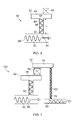
- FIG. 2 shows a pressure indicator first example of the present disclosure.
- the pressure indicator 40 comprises a first reservoir 42 which defines a first enclosed volume 44 (or "pressure tapping") having a first inlet pipe 46 defining a nominal communication path length L 1 .
- the first inlet pipe 46 provides flow communication between the first enclosed volume 44 and a first source of pressurised fluid 50.
- a member 52 is provided in the first inlet pipe 46.
- the member 52 defines one or more communication paths of greater length to that of the nominal communication path length L 1 .
- the member 52 is helicoid and extends at least part of the length of the first inlet pipe 46.
- FIG. 3 A more detailed example of a member 52 having a helicoidal form is shown in Figure 3 .
- the helicoid member 52 has a core 53 which supports a screw thread type formation 55 which defines the helicoid form.
- the screw thread formation 55 has a depth "d".
- the screw thread formation 55 extends the full length of the member 52.
- the screw thread formation 55 is shown with a depth "d" of approximately 30% of the external diameter of the member 52, and the core 53 is shown to be approximately 40% of the external diameter of the member 52.
- the depth of the screw thread formation "d” may be 45% or more of the external diameter of the member 52, with the core 53 being only a small percentage of the overall external diameter of the member 52.
- a large (i.e. deep) screw thread formation 55 is beneficial to provide a helicoid with a large surface area, thereby increasing the range of path lengths between the ends of the inlet pipe 46.
- the screw thread formation 55 is generally triangular in cross section.
- the surface 54 of the member defines a plurality of communication path lengths 56, ranging between the nominal length L 1 ("short” or “fast” paths) and the helical communication path length provided by the surface of the helicoid at the outer diameter of the screw thread 55 ("long” or “slow” paths).
- the term "communication path” is intended to describe the multitude of routes or path lengths between the ends of the inlet pipe 46 which are created by the presence of the helicoid member 52 in the inlet pipe 46. These include any possible route over the surface of the helicoid, over the surface of the inlet pipe 46, in the space between inlet pipe 46 and the helicoid member 52, and in the space between the screw thread formations 55.
- the geometry of the helicoid member 52 will, when the pressure indicator is in use, generate a velocity distribution within the fluid passing along the fluid inlet pipe 46 and around the helicoid member 52 at any given cross section of the inlet pipe 46 and helicoid member 52.
- a multitude of "short"(i.e. “fast”), "long” (i.e.”slow") and intermediate path lengths are provided. Consequently the pressure indicator system has a great many communication path lengths longer than that of the nominal communication path length L 1 which increases the effective length and thereby reduces the natural frequency of the system.
- the helicoid may have a textured and/or irregular surface comprising steps, ripples or pedestals to further increase its external surface area.
- the member 52 may be spaced apart from the wall of the inlet pipe 46 substantially along the whole length of the member 52. Consequently, the member 52 may be spaced apart from the wall of the inlet pipe 46 substantially along the whole length inlet pipe 46. In examples where the member 52 is spaced apart from the wall of the inlet pipe 46, the distance between the largest diameter of the member 52 and the wall of the inlet pipe is substantially constant along substantially the full length of the member 52.
- the outer circumference of the member 52 is in contact with the wall of the inlet pipe 46 along substantially the full length of the member 52.
- the distance between the largest diameter of the helicoid member and the wall of the first inlet pipe is substantially constant along substantially the full length of the helicoid member. That is to say, even when the outer circumference of the member 52 is in contact with the wall of the inlet pipe 46 along substantially the full length of the member 52, the distance between the largest diameter of the helicoid member and the wall of the first inlet pipe 46 is substantially constant in that it is consistently substantially zero, although there may be a small clearance to enable assembly of the member 52 and fluid inlet pipe 46.
- the member 52 may have a length no greater than that the length of the inlet pipe 46.
- the member 52 may not extend beyond the ends of the inlet pipe 46.
- the helicoid member 52 may have a length of at least three times the diameter of the inlet pipe 46.
- the helicoid member 52 may have a length of at least five times the diameter of the inlet pipe 46.
- the member 52 may be an insert placed in the inlet pipe (i.e. a separate component to the inlet pipe 46), or integral with the inlet pipe 46.
- the member 52 may be bonded in position in the inlet pipe 46 or free to move within the inlet pipe 46.
- a pressure transducer 58 may be placed in communication with the enclosed volume 44, either through an orifice in the wall of the reservoir 42 or by abutment with the wall of the reservoir 42. The pressure transducer will thus be able to register variations in pressure 60 in the first source of pressurised fluid 50.
- FIG. 4 A second example of the present disclosure is shown in Figure 4 .
- FIG. 5 A more detailed representation of the arrangement presented in Figure 4 is shown in Figure 5 .
- the pressure indicator 70 of Figure 4 comprises a second reservoir 72 which defines a second enclosed volume 74 having a second inlet pipe 76 for communication between the second enclosed volume 74 and a second source of pressurised fluid 80.
- a member 82 is provided in the second inlet pipe 76, where the member 82 is similar to that of the member 52 in the first inlet pipe 46, having similar characteristics and provided to achieve the same result.
- a differential pressure transducer 84 is provided between and in communication with the first and second enclosed volumes 44,74, for the indication of pressure differences between the first source of pressurised fluid 50 and the second source of pressurised fluid 80.
- the member 82 provides the same effect as that described for the member 52 above.
- An alternative pressure indicator 90 is shown in Figure 6 .
- the features of this example are similar to that shown in Figure 2 , except the member provided to generate the extra communication path lengths is a hollow member 92.
- the hollow member 92 has a first orifice 94.
- the first orifice 94 is towards one end of the member 92.
- a first orifice 94' is provided between the ends of the member 92.
- the first orifice 94 is provided at one end and a second orifice 96 is provided at the opposite end of the member 92.
- the first orifice 94 is provided at one end and a second orifice 94' is provided between the ends of the member 92.
- first orifice 94 is provided at one end, a second orifice 96 is provided at the opposite end of the member and a third orifice 94' is provided between the ends of the member 92. At least one further orifice is provided between the ends of the member 92.
- the hollow member 92 has a longer communication path length than the nominal communication path length L 1 , which thereby increases the effective length of the inlet pipe and reduces the natural frequency of the pressure indicator system.
- the diameter of the hollow member 92 is less than the diameter of the first inlet pipe 46 thereby decreasing the effective diameter of the system.
- the multiple communication path lengths and increased surface area provided by the hollow member 92 results in increased viscous dissipation and frictional losses which provides increased damping of the system, and Helmholtz resonance will be less likely to occur.
- a further pressure indicator 100 is shown in Figure 7 . This is essentially the same as the example of Figure 4 , except that the members 52, 82 have been replaced by hollow members 92, 102 as described in relation to Figure 6 .
- a further pressure indicator 110 is shown in Figure 8 . This is essentially the same as the example of Figure 6 , except that walls 112,114 are provided at the ends of the first inlet pipe 46, with orifices 96,94 that correspond to orifices provided at the ends of the member 92.
- the hollow member 92 is the only means of communication between the first enclosed volume 44 and the first source of pressurised fluid 50.
- the pressure indicator system has a longer communication path length than the nominal communication path length L 1 at a reduced diameter which thereby reduces the natural frequency of the system.
- the increased path length and reduced diameter provides an increased surface area relative to volume and results in increased viscous dissipation and frictional losses which provides increased damping of the system, and Helmholtz resonance will be less likely to occur.
- a further pressure indicator 120 is shown in Figure 9 .
- the member provided to generate the extra communication path lengths is a hollow member 122 with a serpentine form. That is to say, the member 122 is folded back on itself.
- the serpentine form creates different path lengths within the hollow member, thus creating a fluid velocity distribution in the member.
- a multitude of "short"(i.e. "fast"), "long” (i.e.”slow") and intermediate path lengths are provided. Consequently the pressure indicator system has a great many communication path lengths longer than that of the nominal communication path length L 1 which increases the effective length and thereby reduces the natural frequency of the system.
- a further pressure indicator 130 is shown in Figure 10 , in which both a hollow helicoidal member 92 and a hollow serpentine member 122 are provided in the first inlet pipe 46. Additional hollow members may also be provided in the first inlet pipe 46.
- FIG. 11 and Figure 12 are essentially the same as the arrangement of Figures 2, 4 and 5 , and Figures 6 and 7 respectively, except the members provided to generate the extra communication path lengths comprise a porous region 142 which define one or more communication paths of greater length to that of the nominal communication path length L 1 . That is to say, the members 144 of pressure indicators 140,150 are porous.
- the porous members 144 may comprise an open cell structure. The multiple communication path lengths and increased surface area result in increased viscous dissipation and frictional losses which provides increased damping of the pressure indicator system, and Helmholtz resonance will be less likely to occur.
- one end of the member 52,82, hollow member 92,102,122 or porous member 144 may be provided adjacent their respective enclosed volume. This will provide more damping than if the members 52,82,92,102,122,144 are spaced apart from the enclosed volumes.
- a pressure indicator according to the present disclosure plus any equipment attached to it, will thus be less susceptible to damage due to Helmholtz resonance. This provides a means of modifying an existing pressure indicator system of pressure indicating equipment to increase survivability, and which are easier to configure for a wider range of applications.
- the device of the present disclosure may also be easily retrofitted to a system according to Figure 1 by insertion of a member 52,82,92,102,122,144 into an existing system.
- the first and/or second source of pressurised fluid 50,80 may be flowing or static, where the pressure of the fluid rises and falls.
Landscapes
- Physics & Mathematics (AREA)
- General Physics & Mathematics (AREA)
- Measuring Fluid Pressure (AREA)
Abstract
Description
- The present disclosure relates to a pressure indicator.
- A conventional arrangement for indicating pressure is shown in
Figure 1 . This shows apressure indicator 10 which comprises afirst reservoir 12 which defines a first enclosed volume 14 (or "pressure tapping") having afirst inlet pipe 16 defining a nominal communication path length "L". Thefirst inlet pipe 16 provides flow communication between the first enclosedvolume 14 and a first source ofpressurised fluid 20. Asecond reservoir 22 which defines second enclosed volume 24 (or "pressure tapping") having asecond inlet pipe 26 that provides flow communication between the second enclosedvolume 24 and a second source of pressurisedfluid 30 may also be provided, as shown inFigure 1 . Apressure transducer 32 is disposed between the first enclosedvolume 14 and the second enclosedvolume 24, being in communication with both. The first and/or second source ofpressurised fluid Figure 1 , the pressure transducer maybe used to indicate differences in pressure between the first and second source ofpressurised fluid - A problem with this design is that the system may exhibit Helmholtz resonance. The Helmholtz resonance may occur at a frequency which is given approximately by:

- Helmholtz resonance occurs when a pressurised compressible fluid within an enclosed volume (or "cavity") equalizes pressure with respect to a reduced external pressure, i.e. the source of
pressurised fluid - In instances where the external pressure varies at a frequency which is matched to a resonant frequency of the enclosed volume, the resonance will draw energy from the pressure source, and the amplitude of the pressure fluctuations within the enclosed volume will grow until they greatly exceed the amplitude of the pressure fluctuations in the pressure source, and may be sufficient to damage the pressure transducer and/or the structure which defines the inlet pipes and enclosed volumes.
- One way to avoid resonance is to choose dimensions of the enclosed volumes such that the resonant frequencies of the cavities do not coincide with the external pulsing frequencies present in the source of pressurised fluid. However, it may not be possible to achieve this over the entire operational range of the equipment which the pressure indicator is attached to. Alternatively, an error in design may mean that resonance occurs in an unexpected operational range, the only solution of which may be to redesign the enclosed volumes. This may not be possible within the available space, and even if it is, it will incur time and cost penalties.
- Hence a pressure indicator for indicating pressure of a pressure source which is operational over a wide range of operating conditions and exhibits low amplitude Helmholtz resonance at a resonant frequency below the operational range of the pressure indicator is highly desirable.
- Accordingly there is provided a pressure indicator for indicating pressure of a pressure source, the indicator comprising a first reservoir which defines a first enclosed volume having a first inlet pipe for communication between the first enclosed volume and a first source of pressurised fluid and defining a nominal communication path length between the first enclosed volume and a first source of pressurised fluid wherein a member which defines a multitude of communication paths of greater length to that of the nominal communication path length is provided in the first inlet pipe.
- The member provides a multitude of communication paths having a greater length than that of the nominal path length for pressure waves/oscillations to travel along. As a result the effective length of the first inlet pipe will be greater than the actual length of the first inlet pipe. In this context , "effective length" is defined as the theoretical length which defines the resonant frequency of the pipe. As a result the natural frequency of the pressure indicator system is reduced to a value outside of its operational range.
- The effective diameter of the first inlet pipe with member may be less that the actual diameter of the first inlet pipe. In this context, "effective diameter" is defined to mean the theoretical inlet pipe diameter which defines the resonant frequency of the pipe. As a result the resonant frequency is reduced and viscous and frictional damping of pressure oscillation passing over and through the member will be increased and hence the likelihood of resonance is diminished.
- The member may be provided with a number of surfaces which define a corresponding number of communication paths which are longer than the nominal communication path length.
- The member may extend at least part of the length of the first inlet pipe.
- The member may be spaced apart from the wall of the inlet pipe substantially along its whole length.
- The member may be at least in part helicoid.
- The member may be at least in part serpentine.
- The member may be hollow and have a first orifice. The first orifice may be towards one end of the member. The first orifice may be provided between the ends of the member. The first orifice may be provided at one end with a second orifice provided at the opposite end of the member. The first orifice may be provided at one end with a second orifice provided between the ends of the member. The first orifice may be provided at one end, with a second orifice provided at the opposite end of the member and a third orifice provided between the ends of the member. At least one further orifice may be provided between the ends of the member.
- The member may comprise a porous region which defines one or more communication paths of greater length to that of the nominal communication path length.
- The pressure indicator of the present disclosure may also further comprise a pressure transducer in communication with the first enclosed volume.
- The pressure indicator of the present disclosure may also further comprise a second reservoir which defines a second enclosed volume having a second inlet pipe for communication between the second enclosed volume and a second source of pressurised fluid, and the pressure transducer being in communication with the second enclosed volume.
- Examples of the present disclosure will now be described with reference to the accompanying drawings, in which:
-
Figure 1 shows a pressure indicator; -
Figure 2 shows a first example of a pressure indicator according to the present disclosure; -
Figure 3 shows a helicoid member which forms part of a number of examples of the present disclosure. -
Figure 4 shows a second example of a pressure indicator according to the present disclosure; -
Figure 5 shows a more detailed representation of the example ofFigure 4 . -
Figure 6 shows a third example of a pressure indicator according to present disclosure; -
Figure 7 shows a fourth example of a pressure indicator according to the present disclosure; -
Figure 8 shows a fifth example of a pressure indicator according to the present disclosure; -
Figure 9 shows a sixth example of a pressure indicator according to the present disclosure; -
Figure 10 shows a seventh example of a pressure indicator according to the present disclosure; -
Figure 11 shows a eighth example of a pressure indicator according to the present disclosure; and -
Figure 12 shows a ninth example of a pressure indicator according to the present disclosure; -
Figure 2 shows a pressure indicator first example of the present disclosure. Thepressure indicator 40 comprises afirst reservoir 42 which defines a first enclosed volume 44 (or "pressure tapping") having afirst inlet pipe 46 defining a nominal communication path length L1 . Thefirst inlet pipe 46 provides flow communication between the first enclosedvolume 44 and a first source ofpressurised fluid 50. Amember 52 is provided in thefirst inlet pipe 46. Themember 52 defines one or more communication paths of greater length to that of the nominal communication path length L1 . In this example themember 52 is helicoid and extends at least part of the length of thefirst inlet pipe 46. - A more detailed example of a
member 52 having a helicoidal form is shown inFigure 3 . Thehelicoid member 52 has a core 53 which supports a screwthread type formation 55 which defines the helicoid form. Thescrew thread formation 55 has a depth "d". Thescrew thread formation 55 extends the full length of themember 52. InFigure 3 thescrew thread formation 55 is shown with a depth "d" of approximately 30% of the external diameter of themember 52, and thecore 53 is shown to be approximately 40% of the external diameter of themember 52. In an alternative example the depth of the screw thread formation "d" may be 45% or more of the external diameter of themember 52, with the core 53 being only a small percentage of the overall external diameter of themember 52. A large (i.e. deep)screw thread formation 55 is beneficial to provide a helicoid with a large surface area, thereby increasing the range of path lengths between the ends of theinlet pipe 46. Thescrew thread formation 55 is generally triangular in cross section. - The
surface 54 of the member defines a plurality ofcommunication path lengths 56, ranging between the nominal length L1 ("short" or "fast" paths) and the helical communication path length provided by the surface of the helicoid at the outer diameter of the screw thread 55 ("long" or "slow" paths).. The term "communication path" is intended to describe the multitude of routes or path lengths between the ends of theinlet pipe 46 which are created by the presence of thehelicoid member 52 in theinlet pipe 46. These include any possible route over the surface of the helicoid, over the surface of theinlet pipe 46, in the space betweeninlet pipe 46 and thehelicoid member 52, and in the space between thescrew thread formations 55. That is to say the geometry of thehelicoid member 52 will, when the pressure indicator is in use, generate a velocity distribution within the fluid passing along thefluid inlet pipe 46 and around thehelicoid member 52 at any given cross section of theinlet pipe 46 andhelicoid member 52. Hence a multitude of "short"(i.e. "fast"), "long" (i.e."slow") and intermediate path lengths are provided. Consequently the pressure indicator system has a great many communication path lengths longer than that of the nominal communication path length L1 which increases the effective length and thereby reduces the natural frequency of the system. - Multiple communication path lengths (which consequently provide paths of different communication speeds) and increased surface area mean viscous dissipation and frictional losses will increase within the arrangement of the present disclosure providing increased damping of the system, and Helmholtz resonance will be less likely to occur.
- The helicoid may have a textured and/or irregular surface comprising steps, ripples or pedestals to further increase its external surface area.
- As shown in
Figure 3 , themember 52 may be spaced apart from the wall of theinlet pipe 46 substantially along the whole length of themember 52. Consequently, themember 52 may be spaced apart from the wall of theinlet pipe 46 substantially along the wholelength inlet pipe 46. In examples where themember 52 is spaced apart from the wall of theinlet pipe 46, the distance between the largest diameter of themember 52 and the wall of the inlet pipe is substantially constant along substantially the full length of themember 52. - Alternatively, the outer circumference of the
member 52 is in contact with the wall of theinlet pipe 46 along substantially the full length of themember 52. - In both cases, where the
member 52 is spaced apart from the wall of theinlet pipe 46 or in contact with the wall of theinlet pipe 46, it will be appreciated that a minimum clearance may be maintained. In the example where themember 52 is spaced apart from the wall of theinlet pipe 46, the clearance may be small. In the example where themember 52 is nominally in contact with the wall of theinlet pipe 46, a small clearance may be required to permit assembly. - In both cases, where the
member 52 is spaced apart from wall of theinlet pipe 46, or in contact with the wall of theinlet pipe 46, the distance between the largest diameter of the helicoid member and the wall of the first inlet pipe is substantially constant along substantially the full length of the helicoid member. That is to say, even when the outer circumference of themember 52 is in contact with the wall of theinlet pipe 46 along substantially the full length of themember 52, the distance between the largest diameter of the helicoid member and the wall of thefirst inlet pipe 46 is substantially constant in that it is consistently substantially zero, although there may be a small clearance to enable assembly of themember 52 andfluid inlet pipe 46. - The
member 52 may have a length no greater than that the length of theinlet pipe 46. Themember 52 may not extend beyond the ends of theinlet pipe 46. Thehelicoid member 52 may have a length of at least three times the diameter of theinlet pipe 46. Thehelicoid member 52 may have a length of at least five times the diameter of theinlet pipe 46. Themember 52 may be an insert placed in the inlet pipe (i.e. a separate component to the inlet pipe 46), or integral with theinlet pipe 46. Themember 52 may be bonded in position in theinlet pipe 46 or free to move within theinlet pipe 46. There may be provided a location feature on theinlet pipe 46, for example a shoulder on the inner surface of the wall which defines theinlet pipe 46, which themember 52 sits against. Apressure transducer 58 may be placed in communication with theenclosed volume 44, either through an orifice in the wall of thereservoir 42 or by abutment with the wall of thereservoir 42. The pressure transducer will thus be able to register variations inpressure 60 in the first source of pressurisedfluid 50. - A second example of the present disclosure is shown in
Figure 4 . A more detailed representation of the arrangement presented inFigure 4 is shown inFigure 5 . Features in common with the example ofFigure 2 andFigure 3 share the same integer numbers. In addition to all the features of theFigure 2 andFigure 3 examples, thepressure indicator 70 ofFigure 4 comprises asecond reservoir 72 which defines a secondenclosed volume 74 having asecond inlet pipe 76 for communication between the secondenclosed volume 74 and a second source of pressurisedfluid 80. Amember 82 is provided in thesecond inlet pipe 76, where themember 82 is similar to that of themember 52 in thefirst inlet pipe 46, having similar characteristics and provided to achieve the same result. Adifferential pressure transducer 84 is provided between and in communication with the first and secondenclosed volumes fluid 50 and the second source of pressurisedfluid 80. Themember 82 provides the same effect as that described for themember 52 above. - An
alternative pressure indicator 90 is shown inFigure 6 . The features of this example are similar to that shown inFigure 2 , except the member provided to generate the extra communication path lengths is ahollow member 92. Thehollow member 92 has afirst orifice 94. In one example, thefirst orifice 94 is towards one end of themember 92. In a further example, a first orifice 94' is provided between the ends of themember 92. In another example thefirst orifice 94 is provided at one end and asecond orifice 96 is provided at the opposite end of themember 92. In another example thefirst orifice 94 is provided at one end and a second orifice 94' is provided between the ends of themember 92. In an alternative example thefirst orifice 94 is provided at one end, asecond orifice 96 is provided at the opposite end of the member and a third orifice 94' is provided between the ends of themember 92. At least one further orifice is provided between the ends of themember 92. - The
hollow member 92 has a longer communication path length than the nominal communication path length L1 , which thereby increases the effective length of the inlet pipe and reduces the natural frequency of the pressure indicator system. The diameter of thehollow member 92 is less than the diameter of thefirst inlet pipe 46 thereby decreasing the effective diameter of the system. The multiple communication path lengths and increased surface area provided by thehollow member 92 results in increased viscous dissipation and frictional losses which provides increased damping of the system, and Helmholtz resonance will be less likely to occur. - A
further pressure indicator 100 is shown inFigure 7 . This is essentially the same as the example ofFigure 4 , except that themembers hollow members Figure 6 . Afurther pressure indicator 110 is shown inFigure 8 . This is essentially the same as the example ofFigure 6 , except that walls 112,114 are provided at the ends of thefirst inlet pipe 46, withorifices member 92. Hence thehollow member 92 is the only means of communication between the firstenclosed volume 44 and the first source of pressurisedfluid 50. Consequently the pressure indicator system has a longer communication path length than the nominal communication path length L1 at a reduced diameter which thereby reduces the natural frequency of the system. The increased path length and reduced diameter provides an increased surface area relative to volume and results in increased viscous dissipation and frictional losses which provides increased damping of the system, and Helmholtz resonance will be less likely to occur. - A
further pressure indicator 120 is shown inFigure 9 . This is essentially the same as the arrangement ofFigure 6 except the member provided to generate the extra communication path lengths is ahollow member 122 with a serpentine form. That is to say, themember 122 is folded back on itself. The serpentine form creates different path lengths within the hollow member, thus creating a fluid velocity distribution in the member. Hence a multitude of "short"(i.e. "fast"), "long" (i.e."slow") and intermediate path lengths are provided. Consequently the pressure indicator system has a great many communication path lengths longer than that of the nominal communication path length L1 which increases the effective length and thereby reduces the natural frequency of the system. - A
further pressure indicator 130 is shown inFigure 10 , in which both ahollow helicoidal member 92 and ahollow serpentine member 122 are provided in thefirst inlet pipe 46. Additional hollow members may also be provided in thefirst inlet pipe 46. - Further pressure indicators 140,150 are shown in
Figure 11 and Figure 12 , which are essentially the same as the arrangement ofFigures 2, 4 and5 , andFigures 6 and 7 respectively, except the members provided to generate the extra communication path lengths comprise aporous region 142 which define one or more communication paths of greater length to that of the nominal communication path length L1 . That is to say, themembers 144 of pressure indicators 140,150 are porous. Theporous members 144 may comprise an open cell structure. The multiple communication path lengths and increased surface area result in increased viscous dissipation and frictional losses which provides increased damping of the pressure indicator system, and Helmholtz resonance will be less likely to occur. - In examples where the
members porous members 144 extend over only part of the length of their respective orifice tubes, one end of themember porous member 144 may be provided adjacent their respective enclosed volume. This will provide more damping than if themembers - A pressure indicator according to the present disclosure, plus any equipment attached to it, will thus be less susceptible to damage due to Helmholtz resonance. This provides a means of modifying an existing pressure indicator system of pressure indicating equipment to increase survivability, and which are easier to configure for a wider range of applications.
- The device of the present disclosure may also be easily retrofitted to a system according to
Figure 1 by insertion of amember - The first and/or second source of pressurised
fluid
Claims (14)
Applications Claiming Priority (2)
| Application Number | Priority Date | Filing Date | Title |
|---|---|---|---|
| GB1017355.7A GB2489191A (en) | 2010-10-14 | 2010-10-14 | Pressure indicator with an inlet pipe having a path length greater than its nominal length |
| GB201115279A GB2484569B8 (en) | 2010-10-14 | 2011-09-05 | Pressure indicator |
Publications (1)
| Publication Number | Publication Date |
|---|---|
| EP2442085A1 true EP2442085A1 (en) | 2012-04-18 |
Family
ID=43304564
Family Applications (1)
| Application Number | Title | Priority Date | Filing Date |
|---|---|---|---|
| EP11180144A Withdrawn EP2442085A1 (en) | 2010-10-14 | 2011-09-06 | Presure indicator with means for minimizing resonance frequencies |
Country Status (3)
| Country | Link |
|---|---|
| US (1) | US8650962B2 (en) |
| EP (1) | EP2442085A1 (en) |
| GB (2) | GB2489191A (en) |
Cited By (1)
| Publication number | Priority date | Publication date | Assignee | Title |
|---|---|---|---|---|
| EP3809106A1 (en) * | 2019-10-18 | 2021-04-21 | Hamilton Sundstrand Corporation | Pressure ripple mitigation in pressure sensors |
Families Citing this family (2)
| Publication number | Priority date | Publication date | Assignee | Title |
|---|---|---|---|---|
| GB201017351D0 (en) * | 2010-10-14 | 2010-11-24 | Rolls Royce Plc | Pressure indicator |
| MY165599A (en) * | 2014-10-03 | 2018-04-16 | Tlv Co Ltd | Sensor device |
Citations (3)
| Publication number | Priority date | Publication date | Assignee | Title |
|---|---|---|---|---|
| US20060156824A1 (en) * | 2005-01-14 | 2006-07-20 | Mks Instruments, Inc. | Turbo sump for use with capacitive pressure sensor |
| US20070120568A1 (en) * | 2005-11-25 | 2007-05-31 | Per Bjorkman | Shield arrangement for a vacuum cell |
| US20100018319A1 (en) * | 2008-05-09 | 2010-01-28 | Kulite Semiconductor Products, Inc. | Apparatus and method for eliminating varying pressure fluctuations in a pressure transducer |
Family Cites Families (30)
| Publication number | Priority date | Publication date | Assignee | Title |
|---|---|---|---|---|
| US1619444A (en) * | 1926-07-08 | 1927-03-01 | Taylor Doc Gilford | Antichattering device |
| GB570927A (en) | 1943-06-29 | 1945-07-30 | Charles Robert Archibald Grant | Improvements in or relating to pressure gauges |
| US2486133A (en) * | 1945-01-24 | 1949-10-25 | Buckeye Lab Corp | Fluid pressure dampening device |
| US2804093A (en) * | 1954-01-08 | 1957-08-27 | Sterer Engineering & Mfg Compa | Device for absorbing transient pressure fluctuations |
| US3224020A (en) | 1962-01-05 | 1965-12-21 | Hitachi Ltd | Differental pressure transducers |
| GB963607A (en) | 1962-02-26 | 1964-07-15 | Dunedin Engineering Company Lt | Improvements in or relating to damping valves |
| US3505627A (en) * | 1965-10-18 | 1970-04-07 | Anatole J Sipin | Electromagnetic driver for pressure measuring system |
| US3926057A (en) * | 1974-09-26 | 1975-12-16 | Us Agriculture | Spiral manometer |
| SU621981A2 (en) | 1977-03-28 | 1978-08-30 | Государственный Научно-Исследовательский Энергетический Институт Им.Г.М.Кржижановского | Pressure sensor damper |
| US4299253A (en) * | 1979-11-26 | 1981-11-10 | Hydril Company | Pulsation dampener |
| US4413524A (en) * | 1982-03-26 | 1983-11-08 | Dresser Industries, Inc. | Pulsation throttling device for a pressure gauge |
| US4517844A (en) | 1983-06-03 | 1985-05-21 | Steven Powell | Fluid damping device for a compliant system |
| JPS61167832A (en) * | 1985-01-19 | 1986-07-29 | Hiroshi Kasahara | Pressure measuring instrument |
| US4668889A (en) | 1986-06-06 | 1987-05-26 | Adams Donald L | Static overpressure protection system for differential pressure transducer |
| DE8804105U1 (en) | 1988-03-25 | 1989-07-20 | MMM Münchener Medizin Mechanik GmbH, 8000 München | Pressure measuring device |
| DE3823449A1 (en) | 1988-07-11 | 1990-01-18 | Bosch Gmbh Robert | MEASURING DEVICE FOR DETECTING PRESSURE AND TEMPERATURE |
| US5228334A (en) * | 1990-12-28 | 1993-07-20 | Hi-Stat Manufacturing Co., Inc. | Pressure transducer |
| FR2705781B1 (en) | 1993-05-25 | 1995-08-25 | Schlumberger Services Petrol | Membrane pressure sensor comprising an anti-shock protection system, and gradiomanometer incorporating such a sensor. |
| DE19623759A1 (en) | 1996-06-14 | 1997-12-18 | Bosch Gmbh Robert | Fuel injection valve for internal combustion engines |
| US6681636B2 (en) * | 2002-01-16 | 2004-01-27 | Class 1, Inc. | Pressure sensing apparatus having pressure pulse dampener |
| US7021149B2 (en) | 2003-11-28 | 2006-04-04 | Endress & Hauser Gmbh & Co. Kg | Differential pressure sensor with overload damping |
| DE102004002089A1 (en) | 2004-01-15 | 2005-08-04 | Robert Bosch Gmbh | Arrangement for pressure detection in a pressure chamber, in particular in a combustion chamber of an internal combustion engine |
| JP2005257551A (en) | 2004-03-12 | 2005-09-22 | Kawamoto Pump Mfg Co Ltd | Flowrate sensor |
| US7975552B2 (en) | 2006-04-21 | 2011-07-12 | Kulite Semiconductor Products, Inc. | Pressure transducer employing a micro-filter and emulating an infinite tube pressure transducer |
| DE102006024381B3 (en) | 2006-05-24 | 2007-12-06 | Fraunhofer-Gesellschaft zur Förderung der angewandten Forschung e.V. | MEMS vacuum sensor based on the friction principle |
| CN101553719B (en) | 2006-11-22 | 2011-07-06 | 丹福斯有限公司 | A pressure sensor |
| DE102007061184A1 (en) | 2007-12-17 | 2009-06-25 | Endress + Hauser Gmbh + Co. Kg | Differential pressure measuring cell |
| FR2926883B1 (en) | 2008-01-24 | 2010-02-26 | Tokheim Holding Bv | PRESSURE SENSOR DEVICE ADAPTED TO EXPLOSIVE OR CORROSIVE ATMOSPHERES |
| US8561470B2 (en) | 2008-05-09 | 2013-10-22 | Kulite Semiconductor Products, Inc. | Apparatus and method for eliminating varying pressure fluctuations in a pressure transducer |
| GB201017351D0 (en) | 2010-10-14 | 2010-11-24 | Rolls Royce Plc | Pressure indicator |
-
2010
- 2010-10-14 GB GB1017355.7A patent/GB2489191A/en not_active Withdrawn
-
2011
- 2011-09-05 GB GB201115279A patent/GB2484569B8/en active Active
- 2011-09-06 EP EP11180144A patent/EP2442085A1/en not_active Withdrawn
- 2011-09-06 US US13/225,768 patent/US8650962B2/en active Active
Patent Citations (3)
| Publication number | Priority date | Publication date | Assignee | Title |
|---|---|---|---|---|
| US20060156824A1 (en) * | 2005-01-14 | 2006-07-20 | Mks Instruments, Inc. | Turbo sump for use with capacitive pressure sensor |
| US20070120568A1 (en) * | 2005-11-25 | 2007-05-31 | Per Bjorkman | Shield arrangement for a vacuum cell |
| US20100018319A1 (en) * | 2008-05-09 | 2010-01-28 | Kulite Semiconductor Products, Inc. | Apparatus and method for eliminating varying pressure fluctuations in a pressure transducer |
Cited By (2)
| Publication number | Priority date | Publication date | Assignee | Title |
|---|---|---|---|---|
| EP3809106A1 (en) * | 2019-10-18 | 2021-04-21 | Hamilton Sundstrand Corporation | Pressure ripple mitigation in pressure sensors |
| US11619560B2 (en) | 2019-10-18 | 2023-04-04 | Hamilton Sundstrand Corporation | Pressure ripple mitigation in pressure sensors |
Also Published As
| Publication number | Publication date |
|---|---|
| GB2484569A (en) | 2012-04-18 |
| GB2489191A (en) | 2012-09-26 |
| GB2484569B (en) | 2013-02-20 |
| GB2484569A8 (en) | 2013-07-24 |
| US20120090530A1 (en) | 2012-04-19 |
| GB201017355D0 (en) | 2010-11-24 |
| US8650962B2 (en) | 2014-02-18 |
| GB2484569B8 (en) | 2013-07-24 |
| GB201115279D0 (en) | 2011-10-19 |
Similar Documents
| Publication | Publication Date | Title |
|---|---|---|
| EP2831504B1 (en) | Combustion chamber seal segments equipped with damping devices | |
| US8955392B2 (en) | Ultrasonic flowmeter with integrally formed acoustic noise attenuating feature | |
| Jensen et al. | The existence of steady flow in a collapsed tube | |
| CN107810391B (en) | Coriolis mass flow and/or density measurement devices | |
| JP6552180B2 (en) | Ultrasonic flow meter | |
| US8650962B2 (en) | Pressure indicator | |
| EP2963345A1 (en) | Damper for gas turbine | |
| DE102014118367A1 (en) | Measuring transducer of the vibration type and thus formed measuring system | |
| JP4884408B2 (en) | Coriolis flow meter | |
| US8667848B2 (en) | Pressure indicator | |
| US8573061B2 (en) | Pressure indicator | |
| US10094398B2 (en) | Fluid transfer apparatus | |
| CN102798419A (en) | Ultrasonic flow sensor | |
| US20120273298A1 (en) | Silencers for air conditioning systems | |
| JP4693990B2 (en) | Device for measuring the flow rate of liquid in a pipe | |
| US11976766B2 (en) | Protective tube for insertion into a pipe or vessel with reduced sensitivity to vortex induced vibrations | |
| JP3564779B2 (en) | Resonant sound generation prevention device for cavity | |
| US8863588B2 (en) | Flow sensor | |
| EP3568671B1 (en) | Fluid-flow sensor assembly having reinforced sensor body | |
| CN110805494A (en) | The Method of Pipeline Layout Design to Realize the Frequency Modulation of Pipeline | |
| CN110455362A (en) | Flowmeter sensor, flowmeter and method for improving fluid impact vibrating tube | |
| CN103884394A (en) | Multi-pipe mass flowmeter |
Legal Events
| Date | Code | Title | Description |
|---|---|---|---|
| PUAI | Public reference made under article 153(3) epc to a published international application that has entered the european phase |
Free format text: ORIGINAL CODE: 0009012 |
|
| AK | Designated contracting states |
Kind code of ref document: A1 Designated state(s): AL AT BE BG CH CY CZ DE DK EE ES FI FR GB GR HR HU IE IS IT LI LT LU LV MC MK MT NL NO PL PT RO RS SE SI SK SM TR |
|
| AX | Request for extension of the european patent |
Extension state: BA ME |
|
| 17P | Request for examination filed |
Effective date: 20121017 |
|
| RIN1 | Information on inventor provided before grant (corrected) |
Inventor name: ANGUS, DOUGLAS JOHN Inventor name: FITZHUGH, ALEXANDER EDWARD HENRY |
|
| RAP1 | Party data changed (applicant data changed or rights of an application transferred) |
Owner name: ROLLS-ROYCE PLC |
|
| STAA | Information on the status of an ep patent application or granted ep patent |
Free format text: STATUS: EXAMINATION IS IN PROGRESS |
|
| 17Q | First examination report despatched |
Effective date: 20171006 |
|
| STAA | Information on the status of an ep patent application or granted ep patent |
Free format text: STATUS: THE APPLICATION HAS BEEN WITHDRAWN |
|
| 18W | Application withdrawn |
Effective date: 20190829 |