EP2442080A1 - Vorrichtung und Verfahren zur Inspektion von Behältern - Google Patents
Vorrichtung und Verfahren zur Inspektion von Behältern Download PDFInfo
- Publication number
- EP2442080A1 EP2442080A1 EP11183490A EP11183490A EP2442080A1 EP 2442080 A1 EP2442080 A1 EP 2442080A1 EP 11183490 A EP11183490 A EP 11183490A EP 11183490 A EP11183490 A EP 11183490A EP 2442080 A1 EP2442080 A1 EP 2442080A1
- Authority
- EP
- European Patent Office
- Prior art keywords
- light sources
- receiver
- light
- transillumination
- container
- Prior art date
- Legal status (The legal status is an assumption and is not a legal conclusion. Google has not performed a legal analysis and makes no representation as to the accuracy of the status listed.)
- Granted
Links
Images

Classifications
-
- G—PHYSICS
- G01—MEASURING; TESTING
- G01N—INVESTIGATING OR ANALYSING MATERIALS BY DETERMINING THEIR CHEMICAL OR PHYSICAL PROPERTIES
- G01N21/00—Investigating or analysing materials by the use of optical means, i.e. using sub-millimetre waves, infrared, visible or ultraviolet light
- G01N21/84—Systems specially adapted for particular applications
- G01N21/88—Investigating the presence of flaws or contamination
- G01N21/90—Investigating the presence of flaws or contamination in a container or its contents
- G01N21/9018—Dirt detection in containers
-
- G—PHYSICS
- G01—MEASURING; TESTING
- G01F—MEASURING VOLUME, VOLUME FLOW, MASS FLOW OR LIQUID LEVEL; METERING BY VOLUME
- G01F23/00—Indicating or measuring liquid level or level of fluent solid material, e.g. indicating in terms of volume or indicating by means of an alarm
- G01F23/22—Indicating or measuring liquid level or level of fluent solid material, e.g. indicating in terms of volume or indicating by means of an alarm by measuring physical variables, other than linear dimensions, pressure or weight, dependent on the level to be measured, e.g. by difference of heat transfer of steam or water
- G01F23/28—Indicating or measuring liquid level or level of fluent solid material, e.g. indicating in terms of volume or indicating by means of an alarm by measuring physical variables, other than linear dimensions, pressure or weight, dependent on the level to be measured, e.g. by difference of heat transfer of steam or water by measuring the variations of parameters of electromagnetic or acoustic waves applied directly to the liquid or fluent solid material
- G01F23/284—Electromagnetic waves
- G01F23/292—Light, e.g. infrared or ultraviolet
- G01F23/2921—Light, e.g. infrared or ultraviolet for discrete levels
- G01F23/2928—Light, e.g. infrared or ultraviolet for discrete levels using light reflected on the material surface
Definitions
- the invention relates to a device for inspecting containers, in particular residual liquid, the type explained in the preamble of claim 1 and to a corresponding method according to the preamble of claim 9.
- a device and a method of this kind is known from EP-A-618 444 known.
- the known device and the known method work with a pairing of transmitter and receiver operating in the infrared range.
- a plurality of transmitter-receiver pairings are provided, wherein one of the pairings includes a projecting through the container mouth in the bottle and on the bottom of the container lighting device and an obliquely arranged below the bottom receiver receives radiation reflected from the bottom of the bottle, through the reflection was sent to the bottom of the bottle through an area extending between the camber of the bottom of the bottle and the wall of the container, where residual liquid necessarily accumulated.
- the receiver is provided with an evaluation device, with the aid of which it can be determined whether the collected light radiation indicates that light components have been absorbed by a residual liquid present in the container.
- a plurality of transillumination areas can be provided.
- One of the illumination areas can be arranged, for example, directly on the container bottom, in which case only one additional receiver is necessary, which is supplied by the illuminating device radiating through the bottle mouth.
- Further lighting areas with associated transmitter-receiver pairings can be provided in the region of the container wall, radially or obliquely from top to bottom.
- one or more infrared diodes can be used, but the majority of the diodes is metrologically treated as a single diode.
- a disadvantage of this embodiment is the fact that the residual liquid is traversed only by a reflected light beam, wherein the proportion and the direction of reflection at the container bottom strongly depends on the conditions at the container bottom, for example, the reflection angle, so that there is a large source of error.
- contaminants such as oily substances can not be detected with conventional infrared light.
- the known device works only with containers of a single shape and geometry to which the device has been adjusted. When changing to containers of other shapes and dimensions, in particular the receiver must be adjusted to the new reflection angle.
- the invention has for its object to design a device and a method of the known type easier and more reliable.
- the adaptability of the device and the method to the different operating conditions, in particular the different shapes or dimensions of containers to be inspected, is improved.
- the controllability of the light sources can be effected both via a corresponding control of the receiver and via a corresponding control of the light sources.
- the light sources can be interrogated independently of one another, be it that the receiver selectively controls a light source or whether the light source can be switched off and on selectively.
- a further advantage of the device according to the invention by the fact that light sources can be used which emit at different wavelengths.
- the light sources can be tuned specifically to the absorption spectrum of the impurities / residues to be detected, so that, for example, in addition to an aqueous liquid (with more or less strong contamination by a variety of substances), for example, oils can be detected with the inspection devices that only infrared use, can not be determined.
- the illumination device of the device according to the invention preferably contains narrow-band light-emitting diodes as light sources, wherein light-emitting diodes on the one hand because of their low Size and on the other hand because of the possibility to select light-emitting diodes especially after the radiated wave range, are preferred.
- a further advantage is to provide a device according to the invention which has at least one receiver which can receive different wavelengths from a lighting device.
- the illumination device preferably contains a broadband radiation source, particularly preferably broadband light emitting diodes as the light source.
- the broadband spectrum covers a wavelength range from 1 ⁇ m to 3 ⁇ m, in particular from 1.5 ⁇ m to 2.3 ⁇ m.
- the receiver is preferably a receiver which has a plurality of devices, preferably filters, running upstream in the direction of radiation. The filters are designed such that each can be converted from a broadband spectrum into a narrow-band spectrum, so that different wavelengths can be tuned specifically to the absorption spectrum of the impurities / residual amounts to be detected.
- a particularly constructive and control-technically simple solution is to make the light sources selectively on and off.
- the arrangement of the light sources takes place either in series next to each other or in a circle, but then preferably in a plurality of concentric circles.
- the receiver should preferably be selected such that its effective area extends over half of a container bottom when the transillumination region is arranged on the container bottom.
- Fig. 1 shows a schematic representation of a device 1 for the inspection of containers 2, which are shown here as a schematic bottles.
- the containers 2 are made of a transparent or at least partially transparent material, such as the commonly used plastics (PET or the like.) Or glass.
- the container 2 is conveyed in a conventional and not drawn representation by the inspection device 1 and during the passage of the device 1 to residual liquid (water, alkali, oils), impurities, foreign objects or the like. Inspected.
- the device 1 contains a conventional pairing of a light emitter, preferably for light in the infrared range, in the form of a lighting device 3 and a receiver 4.
- the illumination device 3 is arranged below a bottom 2a of the container 2, while the receiver 4 above the mouth opening 2b of the container is arranged to receive the jets sent from the illumination device 3 through the container bottom 2a into the container 2 and exiting through the container opening 2b.
- the illumination device 3 and the receiver 4 are formed so that a transillumination area 5 results, which extends over half the diameter of the bottom 2a.
- the receiver 4 has an effective region 6 capable of covering the illumination region 5.
- the illumination device 3 and the receiver 4 are connected to a control device 7, with the exception of the method steps described below, the evaluation of the receiver 4 intercepted signals, the basic principle of the collected signals to determine the absorbed light components and from these on the Presence of a residual liquid, contamination, a foreign body or the like. To close, is maintained.
- the illumination device 3 contains a plurality of light sources 8, which are used in the preferred embodiment as light emitting diodes and in particular as narrow-band light-emitting diodes, ie light-emitting diodes which emit light radiation in a narrow waveband.
- the light sources 8 are arranged distributed over the transillumination region 5, ie in this case a radial strip over the container bottom 2a, at a distance from one another.
- the arrangement may be in the form of a row (as shown) or in the form of a circle, preferably one Majority of concentric circles, done.
- the arrangement and the distance between the light sources 8 is such that the radiation of each light source 8 is selectively detectable by the receiver 4.
- the illumination device 3 contains five to ten, in particular eight to ten LEDs.
- the receiver 4 has one or more sensors 4a and an optic 4b, which ensures that the rays emerging from the container mouth 2b are conducted into the sensor or the sensors 4a.
- the illumination device 3 can contain light sources 8 of the same type or different types, which can be selectively switched on permanently or in a pulsed manner or switched off selectively.
- the light sources 8 can be of the same type which can be selectively switched on and off by the control device 7. In this way, it is possible to turn on only that light source 8 and to use for measurement, which is directed to a region of the container 2, in which residual liquid is in any case, if any residual liquid in the container 2 is present, ie at the lowest Range with normal (vertical) conveying orientation of the containers. This is for containers with a curved bottom, like those in Fig. 1 illustrated bottle, the lowest point, ie the transition region between the floor dome and the upwardly adjoining side wall. Thereby, the device 1 can be easily adapted to any desired container geometry, in particular each container diameter and shape.
- light sources are used which radiate in at least two wave ranges.
- light sources of different wavelengths could be grouped together into one group, and this group could be grouped in the Fig. 1 be arranged for individual light sources shown way.
- the senor 4a of the receiver 4 spectrally covers a range of approximately 1.5 ⁇ m to 2.0 ⁇ m.
- this receiver light-emitting diodes with two or more different Wavelengths used in this area, which are switched on and off during the measurement in time. This allows the characteristic spectra of different liquids to be ideally distinguished from each other and from the container material.
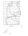
- Fig. 2 shows the unabsorbed light components in a different wavelength transmittance for a pure container material (PET), oil oil (average of various oils), pure water W and contaminated liquor L. Based on these curves, corresponding light sources can be easily selected.
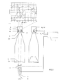
- Fig. 3 shows a schematic representation of another device for inspection of containers 2. This embodiment corresponds to essential parts of the device Fig. 1 , Thus, the previously made explanations apply analogously to this embodiment. Differences to the execution in Fig. 1 exist in the lighting device 3 used and the associated receiver. 4
- the illumination device 3 contains a plurality of light sources 8, which in the preferred embodiment are light emitting diodes and in particular broadband light emitting diodes, i. Light emitting diodes, which emit light radiation in a wide wavelength range, are used.
- the light sources 8 are above the transillumination area 5, i.
- a radial strip over the container bottom 2a arranged distributed at a distance from each other.
- the arrangement may be in the form of a row (as shown) or in the form of a circle, preferably a plurality of concentric circles.
- the arrangement and the distance between each other between the light sources 8 are such that the radiation of each light source 8 is selectively detectable by the receiver 4.
- the illumination device 3 contains five to ten, in particular eight to ten LEDs.
- the receiver 4 upstream in the direction of radiation, filters 9, 10 upstream. These filters 9, 10 can convert the broadband spectrum emitted by the illumination device 3 into a narrowband spectrum.
- the receiver 4 receives via a first Sensor 4a and a first narrow-band filter 9, a first spectrum, ie, a wavelength in a first range of preferably 1.65 ⁇ m - 1.8 ⁇ m.
- the receiver receives via a second sensor 4a 'and a second narrowband filter 10 a second spectrum, ie, a wavelength in a second, preferably different, range of preferably 1.8 ⁇ m - 2.3 ⁇ m. This allows the characteristic spectra of different liquids to be ideally distinguished from each other and from the container material.
- the evaluation of the signals received by the receiver 4 takes place, also in particular with the aid of a comparison with a desired value.
- the at least two sensors 4a, 4a 'and the at least two filters 9, 10 are housed in a receiver housing in this embodiment. But there are also several receivers 4, each with a sensor 4a, 4a 'and a filter 9,10 conceivable.
- the controller 7 In addition to the evaluation of the measurement signals from the receiver 4 and the selective control of the light sources 8, the controller 7 also takes over the synchronization of the measurement with the movement of the containers along their transport path or the like.
- Fig. 4 shows a receiver 4 with two filters 9, 10 in a receiver housing according to the embodiment Fig. 3 ,
- other suitable light sources or radiation sources can be used.
- the reverse arrangement, lighting device above and receiver below, is conceivable.
- the transillumination area can also be provided at other locations of the container wall. It may also be conceivable to use a receiver which is able to detect the individual light sources selectively and without being influenced by the other light sources.
- the described structural and control details can be combined as needed or interchanged.
Landscapes
- Physics & Mathematics (AREA)
- Electromagnetism (AREA)
- General Physics & Mathematics (AREA)
- Fluid Mechanics (AREA)
- Thermal Sciences (AREA)
- General Health & Medical Sciences (AREA)
- Biochemistry (AREA)
- Analytical Chemistry (AREA)
- Immunology (AREA)
- Pathology (AREA)
- Chemical & Material Sciences (AREA)
- Life Sciences & Earth Sciences (AREA)
- Health & Medical Sciences (AREA)
- Investigating Materials By The Use Of Optical Means Adapted For Particular Applications (AREA)
- Investigating Or Analysing Materials By Optical Means (AREA)
Abstract
Description
- Die Erfindung bezieht sich auf eine Vorrichtung zur Inspektion von Behältern, insbesondere auf Restflüssigkeit, der im Oberbegriff von Anspruch 1 erläuterten Art und auf ein entsprechendes Verfahren gemäß dem Oberbegriff des Anspruches 9.
- Eine Vorrichtung und ein Verfahren dieser Art ist aus der
EP-A-618 444 - Es ist weiterhin bekannt, beispielsweise aus der
DE-A-27 38 571 oder derDE-C-195 12 124 , die Beleuchtung unterhalb des Behälterbodens und dem Empfänger oberhalb der Flaschenmündung anzuordnen. Um Messwerte auch aus dem Übergangsbereich zwischen dem gewölbten Behälterboden und der Wandung zu erreichen, wird beispielsweise in derDE 27 38 571 eine Streuscheibe eingesetzt, die das Licht parallel zur Längsachse des Behälters ausrichtet, oder der Empfänger enthält eine Optik (DE 195 12 124 ), die die aus der Flaschenmündung austretenden Durchleuchtungsstrahlen parallel zur Längsachse des Behälters ausrichtet. - Der Erfindung liegt die Aufgabe zugrunde, eine Vorrichtung und ein Verfahren der bekannten Art einfacher und zuverlässiger auszugestalten.
- Die Aufgabe wird bei einer Vorrichtung durch die Merkmale des Anspruches 1 und beim Verfahren durch die Merkmale des Anspruches 9 gelöst.
- Durch die erfindungsgemäße Ausgestaltung, eine Mehrzahl unabhängig voneinander angeordneten und unabhängig voneinander ansteuerbaren Lichtquellen vorzusehen, wird die Anpassungsfähigkeit der Vorrichtung und des Verfahrens an die unterschiedlichen betrieblichen Gegebenheiten, insbesondere die unterschiedlichen Formen bzw. Abmessungen von zu inspizierenden Behältern verbessert. Die Ansteuerbarkeit der Lichtquellen kann sowohl über eine entsprechende Steuerung des Empfängers als auch über eine entsprechende Steuerung der Lichtquellen bewirkt werden.
- Von besonderem Vorteil ist es, wenn die Lichtquellen unabhängig voneinander abfragbar sind, sei es, dass der Empfänger gezielt gerichtet eine Lichtquelle ansteuert oder sei es, dass die Lichtquelle selektiv ab- und angeschaltet werden kann.
- Einen weiteren Vorteil bietet die erfindungsgemäße Vorrichtung durch die Tatsache, dass Lichtquellen eingesetzt werden können, die mit unterschiedlicher Wellenlänge abstrahlen. Dadurch können die Lichtquellen gezielt auf das Absorptionsspektrum der festzustellenden Verunreinigungen/Restmengen abgestimmt werden, so dass beispielsweise neben einer wässrigen Flüssigkeit (mit mehr oder weniger starker Verunreinigung durch die unterschiedlichsten Stoffe), beispielsweise auch Öle festgestellt werden können, die mit Inspektionsvorrichtungen, die lediglich Infrarot verwenden, nicht festgestellt werden können.
- Die Beleuchtungseinrichtung der erfindungsgemäßen Vorrichtung enthält bevorzugt schmalbandige Leuchtdioden als Lichtquellen, wobei Leuchtdioden einerseits wegen ihrer geringen Größe und andererseits wegen der Möglichkeit, Leuchtdioden speziell nach dem ausgestrahlten Wellenbereich auszusuchen, bevorzugt sind.
- Ein weiterer Vorteil ist, eine erfindungsgemäße Vorrichtung bereit zu stellen, welche mindestens einen Empfänger aufweist, der unterschiedliche Wellenlängen von einer Beleuchtungseinrichtung empfangen kann. Die Beleuchtungseinrichtung enthält vorzugsweise eine breitbandige Strahlungsquelle, besonders bevorzugt breitbandige Leuchtdioden als Lichtquelle. Das breitbandige Spektrum umfasst einen Wellenlängenbereich von 1µm bis 3µm, insbesondere von 1,5µm bis 2,3µm. Bei dem Empfänger handelt es sich bevorzugt um einen Empfänger, der eine Mehrzahl an Vorrichtungen, vorzugsweise Filter, in Strahlungsrichtung verlaufend vorgelagert, aufweist. Die Filter sind derart ausgestaltet, dass aus einem breitbandigen Spektrum jeweils in ein schmalbandiges Spektrum umgewandelt werden kann, sodass auch hier unterschiedliche Wellenlängen gezielt auf das Absorptionsspektrum der festzustellenden Verunreinigungen/ Restmengen abgestimmt werden können.
- Es können auch mehrere Empfänger mit jeweils einem schmalbandigen Filter für einen bestimmten Wellenlängenbereich und jeweils einen Sensor vorgesehen werden.
- Eine besonders konstruktiv und steuerungstechnisch einfache Lösung ist es, die Lichtquellen selektiv an- und abschaltbar zu machen.
- Die Anordnung der Lichtquellen erfolgt entweder in Reihe nebeneinander oder im Kreis, dann jedoch bevorzugt in einer Mehrzahl konzentrischer Kreise.
- Der Empfänger sollte bevorzugt so ausgewählt sein, dass sein Wirkungsbereich über die Hälfte eines Behälterbodens reicht, wenn der Durchleuchtungsbereich am Behälterboden angeordnet ist.
- Ein Ausführungsbeispiel der Erfindung wird nachfolgend anhand der Zeichnungen näher erläutert. Es zeigen:
- Fig. 1
- eine schematische Darstellung einer erfindungsgemäßen Vorrichtung zur Inspek-tion von Behältern, und
- Fig. 2
- eine Darstellung von Absorptionsspektren zur Auswahl bevorzugter Wellenlän-gen der Lichtquellen, und
- Fig. 3
- eine schematische Darstellung einer weiteren erfindungsgemäßen Vorrichtung zur Inspektion von Behältern, und
- Fig. 4
- ein Ausführungsbeispiel eines Empfängers mit Filtern.
-
Fig. 1 zeigt in schematischer Darstellung eine Vorrichtung 1 zur Inspektion von Behältern 2, die hier als schematische Flaschen dargestellt sind. Die Behälter 2 bestehen aus einem transparenten bzw. zumindest teilweise transparenten Material, wie beispielsweise die üblicherweise verwendeten Kunststoffe (PET oder dgl.) oder auch Glas. - Der Behälter 2 wird in üblicher und nicht gezeichneter Darstellung durch die Inspektionsvorrichtung 1 gefördert und während des Durchlaufens der Vorrichtung 1 auf Restflüssigkeit (Wasser, Lauge, Öle), Verunreinigungen, Fremdkörper oder dgl. inspiziert.
- Die Vorrichtung 1 enthält eine übliche Paarung aus einem Lichtsender, bevorzugt für Licht im Infrarotbereich, in Form einer Beleuchtungseinrichtung 3 und einem Empfänger 4. Im dargestellten Ausführungsbeispiel ist die Beleuchtungseinrichtung 3 unterhalb eines Bodens 2a des Behälters 2 angeordnet, während der Empfänger 4 oberhalb der Mündungsöffnung 2b des Behälters angeordnet ist, so dass er die von der Beleuchtungseinrichtung 3 durch den Behälterboden 2a in den Behälter 2 geschickten und durch die Behälteröffnung 2b austretenden Strahlen empfängt.
- Im dargestellten Ausführungsbeispiel sind die Beleuchtungseinrichtung 3 und der Empfänger 4 so ausgebildet, dass sich ein Durchleuchtungsbereich 5 ergibt, der über den halben Durchmesser des Bodens 2a reicht. Entsprechend der Größe und Anordnung des Durchleuchtungsbereiches 5 hat der Empfänger 4 einen Wirkungsbereich 6, der in der Lage ist, den Beleuchtungsbereich 5 abzudecken.
- Die Beleuchtungseinrichtung 3 und der Empfänger 4 sind mit einer Steuereinrichtung 7 verbunden, mit der außer den nachfolgend noch beschriebenen Verfahrensschritten, auch die Auswertung der vom Empfänger 4 aufgefangenen Signale erfolgt, wobei das Grundprinzip aus den aufgefangenen Signalen die absorbierten Lichtanteile festzustellen und aus diesen auf das Vorhandensein einer Restflüssigkeit, einer Verschmutzung, eines Fremdkörpers oder dgl. zu schließen, beibehalten wird.
- Die Beleuchtungseinrichtung 3 enthält eine Mehrzahl von Lichtquellen 8, die im bevorzugten Ausführungsbeispiel als Leuchtdioden und insbesondere als schmalbandige Leuchtdioden, d.h. Leuchtdioden, die eine Lichtstrahlung in einem eng begrenzten Wellenbereich aussenden, eingesetzt werden. Die Lichtquellen 8 sind über den Durchleuchtungsbereich 5, d.h. hier einen radialen Streifen über den Behälterboden 2a, mit Abstand zueinander verteilt angeordnet. Die Anordnung kann in Form einer Reihe (wie gezeigt) oder in Form eines Kreises, bevorzugt einer Mehrzahl konzentrischer Kreise, erfolgen. Die Anordnung und der Abstand untereinander zwischen den Lichtquellen 8 ist so bemessen, dass die Strahlung jeder Lichtquelle 8 selektiv vom Empfänger 4 feststellbar ist. Bevorzugt enthält die Beleuchtungseinrichtung 3 fünf bis zehn, insbesondere acht bis zehn LEDs.
- Der Empfänger 4 weist einen oder mehrere Sensoren 4a und eine Optik 4b auf, die dafür sorgt, dass die aus der Behältermündung 2b austretenden Strahlen in den Sensor oder die Sensoren 4a geleitet werden.
- Die Beleuchtungseinrichtung 3 kann Lichtquellen 8 gleicher Art oder unterschiedlicher Art enthalten, die selektiv dauerhaft oder gepulst angeschaltet bzw. selektiv abgeschaltet werden können.
- Wenn lediglich notwendig ist, dass Verbleiben von Restflüssigkeit in der Flasche 2 festzustellen, so können die Lichtquellen 8 von gleicher Art sein, die von der Steuereinrichtung 7 selektiv an- und abschaltbar sind. Auf diese Weise ist es möglich, nur diejenige Lichtquelle 8 einzuschalten und zur Messung zu verwenden, die auf einen Bereich des Behälters 2 gerichtet ist, in dem sich auf jeden Fall Restflüssigkeit befindet, wenn überhaupt Restflüssigkeit im Behälter 2 vorhanden ist, d.h. auf den tiefsten Bereich bei normaler (senkrechter) Förderausrichtung der Behälter. Dies ist bei Behältern mit gewölbtem Boden, wie die in
Fig. 1 dargestellte Flasche, die tiefste Stelle, d.h. der Übergangsbereich zwischen dem Bodendom und der sich nach oben anschließenden Seitenwandung. Dadurch kann die Vorrichtung 1 auf einfache Weise an jede gewünschte Behältergeometrie, insbesondere jeden Behälterdurchmesser und jede Bodenform angepasst werden. - Sollen möglichst viele Verunreinigungen im Behälter festgestellt und gegebenenfalls auch nach ihrer Natur identifiziert werden, so kommen Lichtquellen zum Einsatz, die in wenigstens zwei Wellenbereichen strahlen. Beispielsweise könnten Lichtquellen unterschiedlicher Wellenlänge zu jeweils einer Gruppe zusammengefasst werden und diese Gruppe in der in
Fig. 1 für Einzellichtquellen gezeigten Weise angeordnet werden. Es ist jedoch auch möglich, Lichtquellen mit unterschiedlichen Wellenlängen abwechselnd anzuordnen. Auch hier kann jede einzelne Lichtquelle, egal ob innerhalb einer Gruppe oder als Einzelquelle, selektiv angesteuert werden, was bevorzugt durch ein An- und Abschalten geschieht. Auf diese Weise können nacheinander oder gleichzeitig Lichtstrahlen unterschiedlicher Wellenlängen ausgesandt werden, so dass unterschiedliche Inhaltsstoffe festgestellt und ihrer Art nach identifiziert werden können. - So deckt beispielsweise der Sensor 4a des Empfängers 4 spektral einen Bereich von ca. 1,5 µm bis 2,0 µm ab. Mit diesem Empfänger werden Leuchtdioden mit zwei oder mehr verschiedenen Wellenlängen in diesem Bereich eingesetzt, die bei der Messung zeitlich hintereinander an- und abgeschaltet werden. Dadurch können die charakteristischen Spektren verschiedener Flüssigkeiten ideal voneinander und vom Behältermaterial unterschieden werden. Alternativ wäre es auch möglich, die Empfindlichkeit des Empfängers 4 für verschiedene Wellenlängen einzustellen, so dass die nicht-absorbierten Lichtanteile der verschiedenen Wellenlängen voneinander getrennt werden können.
- Anschließend erfolgt die Auswertung der vom Empfänger 4 empfangenen Signale, was insbesondere ein Vergleich mit einen Sollwert ist, der die nicht- absorbierten Lichtanteile darstellt, wie sie den Durchleuchtungsbereich 5 passieren, wenn keine Verschmutzung und keine fremden Inhaltsstoffe im Behälter 2 vorhanden sind, d.h. die Absorption des reinen Behältermaterials definiert.
-
Fig. 2 zeigt die nicht-absorbierten Lichtanteile bei einer Durchleuchtung mit verschiedenen Wellenlängen für ein reines Behältermaterial (PET), Öl Ö (Mittelwert aus verschiedenen Ölen), reines Wasser W und verschmutzte Lauge L. Anhand dieser Kurven können entsprechende Lichtquellen einfach ausgewählt werden. -
Fig. 3 zeigt eine schematische Darstellung einer weiteren Vorrichtung zur Inspektion von Behältern 2. Dabei entspricht dieses Ausführungsbeispiel in wesentlichen Teilen der Vorrichtung ausFig. 1 . Somit gelten die bereits zuvor gemachten Erläuterungen analog zu dieser Ausführung. Unterschiede zur Ausführung inFig. 1 bestehen bei der eingesetzten Beleuchtungseinrichtung 3 und den zugehörigen Empfänger 4. - Die Beleuchtungseinrichtung 3 enthält eine Mehrzahl von Lichtquellen 8, die im bevorzugten Ausführungsbeispiel als Leuchtdioden und insbesondere als breitbandige Leuchtdioden, d.h. Leuchtdioden, die eine Lichtstrahlung in einem weiten Wellenbereich aussenden, eingesetzt werden. Die Lichtquellen 8 sind über den Durchleuchtungsbereich 5, d.h. hier einen radialen Streifen über den Behälterboden 2a, mit Abstand zueinander verteilt angeordnet. Die Anordnung kann in Form einer Reihe (wie gezeigt) oder in Form eines Kreises, bevorzugt einer Mehrzahl konzentrischer Kreise, erfolgen. Die Anordnung und der Abstand untereinander zwischen den Lichtquellen 8 sind so bemessen, dass die Strahlung jeder Lichtquelle 8 selektiv vom Empfänger 4 feststellbar ist. Bevorzugt enthält die Beleuchtungseinrichtung 3 fünf bis zehn, insbesondere acht bis zehn LEDs.
- Der Empfänger 4 hat, in Strahlungsrichtung verlaufend, Filter 9, 10 vorgelagert. Diese Filter 9, 10 können das von der Beleuchtungseinrichtung 3 ausgestrahlte breitbandige Spektrum in ein schmalbandiges Spektrum umwandeln. Dabei empfängt der Empfänger 4 über einen ersten Sensor 4a und einen ersten schmalbandigen Filter 9 ein erstes Spektrum, d.h. also eine Wellenlänge in einem ersten Bereich von vorzugsweise 1,65µm - 1,8µm. Weiterhin empfängt der Empfänger über einen zweiten Sensor 4a' und einen zweiten schmalbandigen Filter 10 ein zweites Spektrum, d.h. also eine Wellenlänge in einem zweiten, vorzugsweise unterschiedlichen, Bereich von bevorzugt 1,8µm - 2,3µm. Dadurch können hiermit die charakteristischen Spektren verschiedener Flüssigkeiten ideal voneinander und vom Behältermaterial unterschieden werden.
- Auch hier erfolgt anschließend die Auswertung der von dem Empfänger 4 empfangenen Signale, ebenfalls insbesondere mit Hilfe eines Vergleiches mit einem Sollwert.
- Die mindestens zwei Sensoren 4a, 4a' und die mindestens zwei Filter 9, 10 sind bei diesem Ausführungsbeispiel in einem Empfängergehäuse untergebracht. Es sind aber auch mehrere Empfänger 4 mit jeweils einem Sensor 4a, 4a' und einem Filter 9,10 denkbar.
- Die Steuerung 7 übernimmt neben der Auswertung der Messsignale vom Empfänger 4 und die selektive Ansteuerung der Lichtquellen 8 auch die Synchronisierung der Messung mit der Bewegung der Behälter entlang ihres Transportweges oder dgl..
-
Fig. 4 zeigt einen Empfänger 4 mit zwei Filtern 9, 10 in einem Empfängergehäuse gemäß dem Ausführungsbeispiel ausFig. 3 . - In Abwandlung des beschriebenen und bezeichneten Ausführungsbeispiels können andere geeignete Lichtquellen oder Strahlungsquellen eingesetzt werden. Auch die umgekehrte Anordnung, Beleuchtungseinrichtung oben und Empfänger unten, ist denkbar. Der Durchleuchtungsbereich kann auch an anderen Stellen der Behälterwandung vorgesehen sein. Auch ist unter Umständen denkbar, einen Empfänger einzusetzen, der in der Lage ist, die einzelnen Lichtquellen selektiv und ohne Beeinflussung durch die anderen Lichtquellen zu erfassen. Die beschriebenen konstruktiven und steuerungstechnischen Einzelheiten können nach Bedarf kombiniert oder untereinander ausgetauscht werden.
Claims (12)
- Vorrichtung (1) zur Inspektion von Behältern (2), insbesondere auf Restflüssigkeit, mit einer Beleuchtungseinrichtung (3) und einem Empfänger (4), die auf einander gegenüberliegenden Seiten eines Durchleuchtungsbereiches (5) einer Behälterwandung, insbesondere eines Behälterbodens (2a), angeordnet sind, sowie mit einer Einrichtung (7) zum Auswerten der vom Empfänger (4) festgestellten Signale, dadurch gekennzeichnet, dass die Beleuchtungseinrichtung (3) eine Mehrzahl getrennt voneinander über den Durchleuchtungsbereich (5) verteilter und unabhängig voneinander ansteuerbarer Lichtquellen (8) enthält.
- Vorrichtung nach Anspruch 1 dadurch gekennzeichnet, dass die Lichtquellen (8) unabhängig voneinander abfragbar sind.
- Vorrichtung nach Anspruch 1 oder 2, dadurch gekennzeichnet, dass die Lichtquellen (8) unabhängig voneinander an- und abschaltbar sind.
- Vorrichtung nach einem der Ansprüche 1 bis 3, dadurch gekennzeichnet, dass die Beleuchtungseinrichtung (3) Lichtquellen (8) mit wenigstens zwei unterschiedlichen Wellenlängen aufweist.
- Vorrichtung nach einem der Ansprüche 1 bis 4, dadurch gekennzeichnet, dass die Beleuchtungseinrichtung (3) schmalbandige Leuchtdioden als Lichtquellen (8) enthält.
- Vorrichtung nach einem der Ansprüche 1 bis 5, dadurch gekennzeichnet, dass der Empfänger (4) einen Wirkungsbereich (6) aufweist, der über die Hälfte eines Behälterbodens (2a) reicht.
- Vorrichtung nach einem der Ansprüche 1 bis 6, dadurch gekennzeichnet, dass die Lichtquellen (8) in wenigstens einer Reihe über den Durchleuchtungsbereich (5) verteilt angeordnet sind.
- Vorrichtung nach einem der Ansprüche 1 bis 6, dadurch gekennzeichnet, dass die Lichtquellen (8) in wenigstens einer kreisförmigen Anordnung, bevorzugt in einer Mehrzahl konzentrischer Kreise, über den Durchleuchtungsbereich (5) verteilt angeordnet sind.
- Vorrichtung nach einem der Ansprüche 1 bis 3, dadurch gekennzeichnet, dass die Beleuchtungseinrichtung (3) breitbandige Leuchtdioden als Lichtquellen (8) enthält.
- Vorrichtung nach Anspruch 1, dadurch gekennzeichnet, dass der Empfänger (4) mindestens eine schmalbandige Filtervorrichtung (9, 10) enthält.
- Verfahren zur Inspektion von Behältern, insbesondere auf Restflüssigkeit, wobei ein Durchleuchtungsbereich (5) einer Behälterwandung, insbesondere am Behälterboden (2a), durchleuchtet und die absorbierten Lichtanteile festgestellt werden, dadurch gekennzeichnet, dass im Durchleuchtungsbereich (5) zum Feststellen der absorbierten Lichtanteile eine Mehrzahl voneinander räumlich getrennt angeordneter Lichtquellen getrennt voneinander berücksichtigt werden.
- Verfahren nach Anspruch 9, dadurch gekennzeichnet, dass im Durchleuchtungsbereich (5) zum Feststellen der absorbierten Lichtanteile unterschiedliche Wellenlängen berücksichtigt werden.
Applications Claiming Priority (2)
| Application Number | Priority Date | Filing Date | Title |
|---|---|---|---|
| DE102010042331 | 2010-10-12 | ||
| DE102011013551A DE102011013551A1 (de) | 2010-10-12 | 2011-03-10 | Vorrichtung und Verfahren zur Inspektion von Behältern |
Publications (2)
| Publication Number | Publication Date |
|---|---|
| EP2442080A1 true EP2442080A1 (de) | 2012-04-18 |
| EP2442080B1 EP2442080B1 (de) | 2022-09-14 |
Family
ID=44719620
Family Applications (1)
| Application Number | Title | Priority Date | Filing Date |
|---|---|---|---|
| EP11183490.9A Active EP2442080B1 (de) | 2010-10-12 | 2011-09-30 | Vorrichtung und Verfahren zur Inspektion von Behältern |
Country Status (4)
| Country | Link |
|---|---|
| EP (1) | EP2442080B1 (de) |
| CN (1) | CN102565085A (de) |
| DE (1) | DE102011013551A1 (de) |
| ES (1) | ES2927332T3 (de) |
Cited By (2)
| Publication number | Priority date | Publication date | Assignee | Title |
|---|---|---|---|---|
| WO2014086887A1 (de) * | 2012-12-04 | 2014-06-12 | Krones Ag | Inspektionsverfahren und inspektionsvorrichtung für behältnisse |
| WO2016196886A1 (en) * | 2015-06-03 | 2016-12-08 | Industrial Dynamics Company, Ltd. | System and method for inspecting containers using multiple radiation sources |
Families Citing this family (4)
| Publication number | Priority date | Publication date | Assignee | Title |
|---|---|---|---|---|
| CN110431405B (zh) * | 2017-02-06 | 2022-06-14 | 东洋玻璃株式会社 | 玻璃瓶的检查装置 |
| DE102022123099A1 (de) | 2022-09-12 | 2024-03-14 | Emhart Glass Sa | Verfahren und Vorrichtung zum Erzeugen einer Abbildung eines Bodens eines Glasgefäßes |
| DE102024121199A1 (de) | 2024-07-25 | 2026-01-29 | Emhart Glass Sa | Verfahren und Vorrichtung zum Inspizieren des Bodens eines Gefäßes |
| DE102024207877A1 (de) * | 2024-08-19 | 2026-02-19 | Unisensor Sensorsysteme Gmbh | Vorrichtung und Verfahren zum insbesondere kontaktlosen Untersuchen von Behältern auf Fremdstoffe |
Citations (7)
| Publication number | Priority date | Publication date | Assignee | Title |
|---|---|---|---|---|
| DE2738571A1 (de) | 1976-11-05 | 1978-05-18 | Ind Dynamics Co | Laugenerfassungssystem |
| EP0618444A1 (de) | 1993-03-04 | 1994-10-05 | Elpatronic Ag | Verfahren und Vorrichtung zum Ermitteln von Restflüssigkeit in einer Flasche |
| DE19512124A1 (de) | 1995-04-04 | 1996-10-10 | Kettner Verpackungsmaschf | Vorrichtung zum Überprüfen von Flaschen auf Normabweichungen |
| EP1176416A1 (de) * | 2000-02-03 | 2002-01-30 | Suntory Limited | Verfahren und vorrichtung zum abbilden der flüssigkeit in einem behälter |
| US6433338B1 (en) * | 1998-02-09 | 2002-08-13 | Tomra Systems Asa | Method and device for identification of a type of material in an object and utilization therefor |
| WO2006011803A2 (en) * | 2004-07-30 | 2006-02-02 | Eagle Vision Systems B.V. | Apparatus and method for checking of containers |
| WO2008140473A2 (en) * | 2006-10-26 | 2008-11-20 | Polestar Technologies, Inc. | Optical system and method for inspection and characterization of liquids in vessels |
Family Cites Families (4)
| Publication number | Priority date | Publication date | Assignee | Title |
|---|---|---|---|---|
| DE9415768U1 (de) * | 1994-09-30 | 1996-02-01 | Max Kettner Verpackungsmaschinenfabrik GmbH & Co KG, 83026 Rosenheim | Vorrichtung zum Überprüfen von Flaschen auf Normabweichungen in Form von Beschädigung und/oder Fremdkörpern |
| CN2620274Y (zh) * | 2003-01-23 | 2004-06-09 | 王耀南 | 高速自动化流水生产线上的多传感器检测设备 |
| CN1474177A (zh) * | 2003-08-08 | 2004-02-11 | 王耀南 | 多传感器融合智能透明容器检测设备及检测方法 |
| CN101105460A (zh) * | 2007-05-15 | 2008-01-16 | 广州市万世德包装机械有限公司 | 多功能验瓶机 |
-
2011
- 2011-03-10 DE DE102011013551A patent/DE102011013551A1/de not_active Ceased
- 2011-09-30 ES ES11183490T patent/ES2927332T3/es active Active
- 2011-09-30 EP EP11183490.9A patent/EP2442080B1/de active Active
- 2011-10-11 CN CN2011103153344A patent/CN102565085A/zh active Pending
Patent Citations (8)
| Publication number | Priority date | Publication date | Assignee | Title |
|---|---|---|---|---|
| DE2738571A1 (de) | 1976-11-05 | 1978-05-18 | Ind Dynamics Co | Laugenerfassungssystem |
| EP0618444A1 (de) | 1993-03-04 | 1994-10-05 | Elpatronic Ag | Verfahren und Vorrichtung zum Ermitteln von Restflüssigkeit in einer Flasche |
| DE19512124A1 (de) | 1995-04-04 | 1996-10-10 | Kettner Verpackungsmaschf | Vorrichtung zum Überprüfen von Flaschen auf Normabweichungen |
| DE19512124C2 (de) | 1995-04-04 | 2000-04-06 | Kettner Gmbh | Vorrichtung zum Überprüfen von Flaschen auf Normabweichungen in Form von Beschädigungen und/oder Fremdkörpern, insbesondere zum Erkennen von Restflüssigkeiten |
| US6433338B1 (en) * | 1998-02-09 | 2002-08-13 | Tomra Systems Asa | Method and device for identification of a type of material in an object and utilization therefor |
| EP1176416A1 (de) * | 2000-02-03 | 2002-01-30 | Suntory Limited | Verfahren und vorrichtung zum abbilden der flüssigkeit in einem behälter |
| WO2006011803A2 (en) * | 2004-07-30 | 2006-02-02 | Eagle Vision Systems B.V. | Apparatus and method for checking of containers |
| WO2008140473A2 (en) * | 2006-10-26 | 2008-11-20 | Polestar Technologies, Inc. | Optical system and method for inspection and characterization of liquids in vessels |
Cited By (3)
| Publication number | Priority date | Publication date | Assignee | Title |
|---|---|---|---|---|
| WO2014086887A1 (de) * | 2012-12-04 | 2014-06-12 | Krones Ag | Inspektionsverfahren und inspektionsvorrichtung für behältnisse |
| US9482580B2 (en) | 2012-12-04 | 2016-11-01 | Krones Ag | Inspection method and inspection device for containers |
| WO2016196886A1 (en) * | 2015-06-03 | 2016-12-08 | Industrial Dynamics Company, Ltd. | System and method for inspecting containers using multiple radiation sources |
Also Published As
| Publication number | Publication date |
|---|---|
| DE102011013551A1 (de) | 2012-04-12 |
| CN102565085A (zh) | 2012-07-11 |
| EP2442080B1 (de) | 2022-09-14 |
| ES2927332T3 (es) | 2022-11-04 |
Similar Documents
| Publication | Publication Date | Title |
|---|---|---|
| EP2442080B1 (de) | Vorrichtung und Verfahren zur Inspektion von Behältern | |
| EP2450696B1 (de) | Vorrichtung und Verfahren zum Inspizieren von Behältnissen | |
| EP2193345B1 (de) | Optisches sensorsystem | |
| EP2718696B1 (de) | Leerflascheninspektion | |
| DE69021753T2 (de) | Doppel- und Simultanprüfung. | |
| DE102012009783B3 (de) | Verfahren und Vorrichtung zur Inspektion von Leerflaschen | |
| EP2993464B1 (de) | Vorrichtung und verfahren zur qualitätskontrolle transparenter objekte | |
| WO2012062449A1 (de) | Verfahren zur funktionskontrolle einer inspektionsvorrichtung und vorrichtung zur inspektion eines produktsstroms | |
| EP2513875B1 (de) | Spektralsensor zur prüfung von wertdokumenten | |
| EP1884804A1 (de) | Entfernungsmessgerät | |
| WO2002086463A2 (de) | Transmissionssensor | |
| EP2533032A1 (de) | Messverfahren und Messvorrichtung zur Ermittlung von Transmissions- und/oder Reflektionseigenschaften | |
| DE3113248C2 (de) | Vorrichtung zur Entnahme von Flüssigkeiten aus Behältern im Analysenmaßstab | |
| EP3110701B1 (de) | Behälterinspektionsvorrichtung | |
| DE102015007034B4 (de) | Verfahren zum Betrieb eines Parkassistenzsystems eines Kraftfahrzeugs und Kraftfahrzeug | |
| DE102007036621A1 (de) | Verfahren und Vorrichtung zur Untersuchung von Flaschen aus Kunststoff oder Glas auf vorgewählte Eigenschaften | |
| DE102017101271A1 (de) | Sensor zur erfassung einer herzfrequenz und/oder eines blutsauerstoffgehalts und verfahren zum betrieb eines sensors | |
| DE102006044792A1 (de) | Sensor zur Detektion von Schmutz und/oder Regen und Verfahren zum Betreiben eines Sensors | |
| EP3910314B1 (de) | Verfahren und vorrichtung zur analyse der wechselwirkung zwischen einer oberfläche einer probe und einer flüssigkeit | |
| WO2023017054A1 (de) | Lidar-sensorvorrichtung und messverfahren | |
| EP2671649A1 (de) | Vorrichtung zur Identifizierung einer Flasche | |
| DE202012104043U1 (de) | Inspektionsvorrichtung für Behältnismündungen | |
| DE112016001235T5 (de) | Erkennungsvorrichtung für den Anhäufungszustand von Spänen | |
| EP3480571A2 (de) | Vorrichtung zum optischen erkennen von objekten | |
| EP2065732A2 (de) | Optischer Sensor und Verfahren zur Positionsbestimmung von Objekten |
Legal Events
| Date | Code | Title | Description |
|---|---|---|---|
| PUAI | Public reference made under article 153(3) epc to a published international application that has entered the european phase |
Free format text: ORIGINAL CODE: 0009012 |
|
| AK | Designated contracting states |
Kind code of ref document: A1 Designated state(s): AL AT BE BG CH CY CZ DE DK EE ES FI FR GB GR HR HU IE IS IT LI LT LU LV MC MK MT NL NO PL PT RO RS SE SI SK SM TR |
|
| AX | Request for extension of the european patent |
Extension state: BA ME |
|
| 17P | Request for examination filed |
Effective date: 20121018 |
|
| STAA | Information on the status of an ep patent application or granted ep patent |
Free format text: STATUS: EXAMINATION IS IN PROGRESS |
|
| 17Q | First examination report despatched |
Effective date: 20170713 |
|
| GRAP | Despatch of communication of intention to grant a patent |
Free format text: ORIGINAL CODE: EPIDOSNIGR1 |
|
| STAA | Information on the status of an ep patent application or granted ep patent |
Free format text: STATUS: GRANT OF PATENT IS INTENDED |
|
| INTG | Intention to grant announced |
Effective date: 20220511 |
|
| GRAS | Grant fee paid |
Free format text: ORIGINAL CODE: EPIDOSNIGR3 |
|
| GRAA | (expected) grant |
Free format text: ORIGINAL CODE: 0009210 |
|
| STAA | Information on the status of an ep patent application or granted ep patent |
Free format text: STATUS: THE PATENT HAS BEEN GRANTED |
|
| AK | Designated contracting states |
Kind code of ref document: B1 Designated state(s): AL AT BE BG CH CY CZ DE DK EE ES FI FR GB GR HR HU IE IS IT LI LT LU LV MC MK MT NL NO PL PT RO RS SE SI SK SM TR |
|
| REG | Reference to a national code |
Ref country code: GB Ref legal event code: FG4D Free format text: NOT ENGLISH |
|
| REG | Reference to a national code |
Ref country code: CH Ref legal event code: EP |
|
| REG | Reference to a national code |
Ref country code: DE Ref legal event code: R096 Ref document number: 502011017378 Country of ref document: DE |
|
| REG | Reference to a national code |
Ref country code: IE Ref legal event code: FG4D Free format text: LANGUAGE OF EP DOCUMENT: GERMAN |
|
| REG | Reference to a national code |
Ref country code: AT Ref legal event code: REF Ref document number: 1518969 Country of ref document: AT Kind code of ref document: T Effective date: 20221015 |
|
| REG | Reference to a national code |
Ref country code: ES Ref legal event code: FG2A Ref document number: 2927332 Country of ref document: ES Kind code of ref document: T3 Effective date: 20221104 |
|
| REG | Reference to a national code |
Ref country code: LT Ref legal event code: MG9D |
|
| PG25 | Lapsed in a contracting state [announced via postgrant information from national office to epo] |
Ref country code: SE Free format text: LAPSE BECAUSE OF FAILURE TO SUBMIT A TRANSLATION OF THE DESCRIPTION OR TO PAY THE FEE WITHIN THE PRESCRIBED TIME-LIMIT Effective date: 20220914 Ref country code: RS Free format text: LAPSE BECAUSE OF FAILURE TO SUBMIT A TRANSLATION OF THE DESCRIPTION OR TO PAY THE FEE WITHIN THE PRESCRIBED TIME-LIMIT Effective date: 20220914 Ref country code: NO Free format text: LAPSE BECAUSE OF FAILURE TO SUBMIT A TRANSLATION OF THE DESCRIPTION OR TO PAY THE FEE WITHIN THE PRESCRIBED TIME-LIMIT Effective date: 20221214 Ref country code: LV Free format text: LAPSE BECAUSE OF FAILURE TO SUBMIT A TRANSLATION OF THE DESCRIPTION OR TO PAY THE FEE WITHIN THE PRESCRIBED TIME-LIMIT Effective date: 20220914 Ref country code: LT Free format text: LAPSE BECAUSE OF FAILURE TO SUBMIT A TRANSLATION OF THE DESCRIPTION OR TO PAY THE FEE WITHIN THE PRESCRIBED TIME-LIMIT Effective date: 20220914 Ref country code: FI Free format text: LAPSE BECAUSE OF FAILURE TO SUBMIT A TRANSLATION OF THE DESCRIPTION OR TO PAY THE FEE WITHIN THE PRESCRIBED TIME-LIMIT Effective date: 20220914 |
|
| PG25 | Lapsed in a contracting state [announced via postgrant information from national office to epo] |
Ref country code: HR Free format text: LAPSE BECAUSE OF FAILURE TO SUBMIT A TRANSLATION OF THE DESCRIPTION OR TO PAY THE FEE WITHIN THE PRESCRIBED TIME-LIMIT Effective date: 20220914 Ref country code: GR Free format text: LAPSE BECAUSE OF FAILURE TO SUBMIT A TRANSLATION OF THE DESCRIPTION OR TO PAY THE FEE WITHIN THE PRESCRIBED TIME-LIMIT Effective date: 20221215 |
|
| PG25 | Lapsed in a contracting state [announced via postgrant information from national office to epo] |
Ref country code: SM Free format text: LAPSE BECAUSE OF FAILURE TO SUBMIT A TRANSLATION OF THE DESCRIPTION OR TO PAY THE FEE WITHIN THE PRESCRIBED TIME-LIMIT Effective date: 20220914 Ref country code: RO Free format text: LAPSE BECAUSE OF FAILURE TO SUBMIT A TRANSLATION OF THE DESCRIPTION OR TO PAY THE FEE WITHIN THE PRESCRIBED TIME-LIMIT Effective date: 20220914 Ref country code: PT Free format text: LAPSE BECAUSE OF FAILURE TO SUBMIT A TRANSLATION OF THE DESCRIPTION OR TO PAY THE FEE WITHIN THE PRESCRIBED TIME-LIMIT Effective date: 20230116 Ref country code: CZ Free format text: LAPSE BECAUSE OF FAILURE TO SUBMIT A TRANSLATION OF THE DESCRIPTION OR TO PAY THE FEE WITHIN THE PRESCRIBED TIME-LIMIT Effective date: 20220914 |
|
| REG | Reference to a national code |
Ref country code: CH Ref legal event code: PL |
|
| REG | Reference to a national code |
Ref country code: BE Ref legal event code: MM Effective date: 20220930 |
|
| PG25 | Lapsed in a contracting state [announced via postgrant information from national office to epo] |
Ref country code: SK Free format text: LAPSE BECAUSE OF FAILURE TO SUBMIT A TRANSLATION OF THE DESCRIPTION OR TO PAY THE FEE WITHIN THE PRESCRIBED TIME-LIMIT Effective date: 20220914 Ref country code: PL Free format text: LAPSE BECAUSE OF FAILURE TO SUBMIT A TRANSLATION OF THE DESCRIPTION OR TO PAY THE FEE WITHIN THE PRESCRIBED TIME-LIMIT Effective date: 20220914 Ref country code: IS Free format text: LAPSE BECAUSE OF FAILURE TO SUBMIT A TRANSLATION OF THE DESCRIPTION OR TO PAY THE FEE WITHIN THE PRESCRIBED TIME-LIMIT Effective date: 20230114 Ref country code: EE Free format text: LAPSE BECAUSE OF FAILURE TO SUBMIT A TRANSLATION OF THE DESCRIPTION OR TO PAY THE FEE WITHIN THE PRESCRIBED TIME-LIMIT Effective date: 20220914 |
|
| REG | Reference to a national code |
Ref country code: DE Ref legal event code: R097 Ref document number: 502011017378 Country of ref document: DE |
|
| PG25 | Lapsed in a contracting state [announced via postgrant information from national office to epo] |
Ref country code: NL Free format text: LAPSE BECAUSE OF FAILURE TO SUBMIT A TRANSLATION OF THE DESCRIPTION OR TO PAY THE FEE WITHIN THE PRESCRIBED TIME-LIMIT Effective date: 20220914 Ref country code: MC Free format text: LAPSE BECAUSE OF FAILURE TO SUBMIT A TRANSLATION OF THE DESCRIPTION OR TO PAY THE FEE WITHIN THE PRESCRIBED TIME-LIMIT Effective date: 20220914 Ref country code: LU Free format text: LAPSE BECAUSE OF NON-PAYMENT OF DUE FEES Effective date: 20220930 Ref country code: AL Free format text: LAPSE BECAUSE OF FAILURE TO SUBMIT A TRANSLATION OF THE DESCRIPTION OR TO PAY THE FEE WITHIN THE PRESCRIBED TIME-LIMIT Effective date: 20220914 |
|
| PLBE | No opposition filed within time limit |
Free format text: ORIGINAL CODE: 0009261 |
|
| STAA | Information on the status of an ep patent application or granted ep patent |
Free format text: STATUS: NO OPPOSITION FILED WITHIN TIME LIMIT |
|
| PG25 | Lapsed in a contracting state [announced via postgrant information from national office to epo] |
Ref country code: LI Free format text: LAPSE BECAUSE OF NON-PAYMENT OF DUE FEES Effective date: 20220930 Ref country code: IE Free format text: LAPSE BECAUSE OF NON-PAYMENT OF DUE FEES Effective date: 20220930 Ref country code: DK Free format text: LAPSE BECAUSE OF FAILURE TO SUBMIT A TRANSLATION OF THE DESCRIPTION OR TO PAY THE FEE WITHIN THE PRESCRIBED TIME-LIMIT Effective date: 20220914 Ref country code: CH Free format text: LAPSE BECAUSE OF NON-PAYMENT OF DUE FEES Effective date: 20220930 |
|
| 26N | No opposition filed |
Effective date: 20230615 |
|
| PG25 | Lapsed in a contracting state [announced via postgrant information from national office to epo] |
Ref country code: SI Free format text: LAPSE BECAUSE OF FAILURE TO SUBMIT A TRANSLATION OF THE DESCRIPTION OR TO PAY THE FEE WITHIN THE PRESCRIBED TIME-LIMIT Effective date: 20220914 |
|
| PG25 | Lapsed in a contracting state [announced via postgrant information from national office to epo] |
Ref country code: BE Free format text: LAPSE BECAUSE OF NON-PAYMENT OF DUE FEES Effective date: 20220930 |
|
| REG | Reference to a national code |
Ref country code: AT Ref legal event code: MM01 Ref document number: 1518969 Country of ref document: AT Kind code of ref document: T Effective date: 20220930 |
|
| PG25 | Lapsed in a contracting state [announced via postgrant information from national office to epo] |
Ref country code: AT Free format text: LAPSE BECAUSE OF NON-PAYMENT OF DUE FEES Effective date: 20220930 |
|
| PG25 | Lapsed in a contracting state [announced via postgrant information from national office to epo] |
Ref country code: HU Free format text: LAPSE BECAUSE OF FAILURE TO SUBMIT A TRANSLATION OF THE DESCRIPTION OR TO PAY THE FEE WITHIN THE PRESCRIBED TIME-LIMIT; INVALID AB INITIO Effective date: 20110930 |
|
| PG25 | Lapsed in a contracting state [announced via postgrant information from national office to epo] |
Ref country code: CY Free format text: LAPSE BECAUSE OF FAILURE TO SUBMIT A TRANSLATION OF THE DESCRIPTION OR TO PAY THE FEE WITHIN THE PRESCRIBED TIME-LIMIT Effective date: 20220914 |
|
| PG25 | Lapsed in a contracting state [announced via postgrant information from national office to epo] |
Ref country code: MK Free format text: LAPSE BECAUSE OF FAILURE TO SUBMIT A TRANSLATION OF THE DESCRIPTION OR TO PAY THE FEE WITHIN THE PRESCRIBED TIME-LIMIT Effective date: 20220914 |
|
| PG25 | Lapsed in a contracting state [announced via postgrant information from national office to epo] |
Ref country code: TR Free format text: LAPSE BECAUSE OF FAILURE TO SUBMIT A TRANSLATION OF THE DESCRIPTION OR TO PAY THE FEE WITHIN THE PRESCRIBED TIME-LIMIT Effective date: 20220914 |
|
| PG25 | Lapsed in a contracting state [announced via postgrant information from national office to epo] |
Ref country code: BG Free format text: LAPSE BECAUSE OF FAILURE TO SUBMIT A TRANSLATION OF THE DESCRIPTION OR TO PAY THE FEE WITHIN THE PRESCRIBED TIME-LIMIT Effective date: 20220914 |
|
| PG25 | Lapsed in a contracting state [announced via postgrant information from national office to epo] |
Ref country code: MT Free format text: LAPSE BECAUSE OF FAILURE TO SUBMIT A TRANSLATION OF THE DESCRIPTION OR TO PAY THE FEE WITHIN THE PRESCRIBED TIME-LIMIT Effective date: 20220914 |
|
| PGFP | Annual fee paid to national office [announced via postgrant information from national office to epo] |
Ref country code: GB Payment date: 20240808 Year of fee payment: 14 |
|
| PGFP | Annual fee paid to national office [announced via postgrant information from national office to epo] |
Ref country code: DE Payment date: 20250805 Year of fee payment: 15 |
|
| PGFP | Annual fee paid to national office [announced via postgrant information from national office to epo] |
Ref country code: IT Payment date: 20250825 Year of fee payment: 15 |
|
| PGFP | Annual fee paid to national office [announced via postgrant information from national office to epo] |
Ref country code: FR Payment date: 20250808 Year of fee payment: 15 |
|
| PGFP | Annual fee paid to national office [announced via postgrant information from national office to epo] |
Ref country code: ES Payment date: 20251014 Year of fee payment: 15 |