EP2441965A1 - Centrifugal compressor - Google Patents
Centrifugal compressor Download PDFInfo
- Publication number
- EP2441965A1 EP2441965A1 EP10816914A EP10816914A EP2441965A1 EP 2441965 A1 EP2441965 A1 EP 2441965A1 EP 10816914 A EP10816914 A EP 10816914A EP 10816914 A EP10816914 A EP 10816914A EP 2441965 A1 EP2441965 A1 EP 2441965A1
- Authority
- EP
- European Patent Office
- Prior art keywords
- forming section
- path forming
- impeller
- resin housing
- wall
- Prior art date
- Legal status (The legal status is an assumption and is not a legal conclusion. Google has not performed a legal analysis and makes no representation as to the accuracy of the status listed.)
- Withdrawn
Links
- 229920005989 resin Polymers 0.000 claims abstract description 93
- 239000011347 resin Substances 0.000 claims abstract description 93
- 230000002787 reinforcement Effects 0.000 claims description 11
- 238000011144 upstream manufacturing Methods 0.000 claims description 7
- 229910052751 metal Inorganic materials 0.000 claims description 6
- 239000002184 metal Substances 0.000 claims description 6
- 229910010293 ceramic material Inorganic materials 0.000 claims description 4
- 239000003365 glass fiber Substances 0.000 claims description 3
- 230000006835 compression Effects 0.000 abstract description 11
- 238000007906 compression Methods 0.000 abstract description 11
- 230000009467 reduction Effects 0.000 abstract description 8
- 125000006850 spacer group Chemical group 0.000 abstract description 3
- 239000003570 air Substances 0.000 description 8
- 238000004519 manufacturing process Methods 0.000 description 8
- 239000000463 material Substances 0.000 description 6
- 238000001746 injection moulding Methods 0.000 description 5
- 230000008901 benefit Effects 0.000 description 4
- 238000000465 moulding Methods 0.000 description 4
- 229910052782 aluminium Inorganic materials 0.000 description 3
- XAGFODPZIPBFFR-UHFFFAOYSA-N aluminium Chemical compound [Al] XAGFODPZIPBFFR-UHFFFAOYSA-N 0.000 description 3
- 238000005452 bending Methods 0.000 description 3
- 230000000694 effects Effects 0.000 description 3
- 239000005060 rubber Substances 0.000 description 3
- 229910000975 Carbon steel Inorganic materials 0.000 description 2
- 239000010962 carbon steel Substances 0.000 description 2
- 239000000919 ceramic Substances 0.000 description 2
- 239000011094 fiberboard Substances 0.000 description 2
- 239000011521 glass Substances 0.000 description 2
- 230000003068 static effect Effects 0.000 description 2
- 229920005992 thermoplastic resin Polymers 0.000 description 2
- 229910001018 Cast iron Inorganic materials 0.000 description 1
- 239000012080 ambient air Substances 0.000 description 1
- 230000008859 change Effects 0.000 description 1
- 230000003247 decreasing effect Effects 0.000 description 1
- 229920006351 engineering plastic Polymers 0.000 description 1
- 230000007246 mechanism Effects 0.000 description 1
- 230000003014 reinforcing effect Effects 0.000 description 1
- 239000000243 solution Substances 0.000 description 1
- 239000004634 thermosetting polymer Substances 0.000 description 1
Images


Classifications
-
- F—MECHANICAL ENGINEERING; LIGHTING; HEATING; WEAPONS; BLASTING
- F04—POSITIVE - DISPLACEMENT MACHINES FOR LIQUIDS; PUMPS FOR LIQUIDS OR ELASTIC FLUIDS
- F04D—NON-POSITIVE-DISPLACEMENT PUMPS
- F04D29/00—Details, component parts, or accessories
- F04D29/02—Selection of particular materials
- F04D29/023—Selection of particular materials especially adapted for elastic fluid pumps
-
- F—MECHANICAL ENGINEERING; LIGHTING; HEATING; WEAPONS; BLASTING
- F04—POSITIVE - DISPLACEMENT MACHINES FOR LIQUIDS; PUMPS FOR LIQUIDS OR ELASTIC FLUIDS
- F04D—NON-POSITIVE-DISPLACEMENT PUMPS
- F04D29/00—Details, component parts, or accessories
- F04D29/08—Sealings
- F04D29/16—Sealings between pressure and suction sides
- F04D29/161—Sealings between pressure and suction sides especially adapted for elastic fluid pumps
- F04D29/162—Sealings between pressure and suction sides especially adapted for elastic fluid pumps of a centrifugal flow wheel
-
- F—MECHANICAL ENGINEERING; LIGHTING; HEATING; WEAPONS; BLASTING
- F04—POSITIVE - DISPLACEMENT MACHINES FOR LIQUIDS; PUMPS FOR LIQUIDS OR ELASTIC FLUIDS
- F04D—NON-POSITIVE-DISPLACEMENT PUMPS
- F04D29/00—Details, component parts, or accessories
- F04D29/40—Casings; Connections of working fluid
- F04D29/42—Casings; Connections of working fluid for radial or helico-centrifugal pumps
- F04D29/4206—Casings; Connections of working fluid for radial or helico-centrifugal pumps especially adapted for elastic fluid pumps
-
- F—MECHANICAL ENGINEERING; LIGHTING; HEATING; WEAPONS; BLASTING
- F04—POSITIVE - DISPLACEMENT MACHINES FOR LIQUIDS; PUMPS FOR LIQUIDS OR ELASTIC FLUIDS
- F04D—NON-POSITIVE-DISPLACEMENT PUMPS
- F04D29/00—Details, component parts, or accessories
- F04D29/40—Casings; Connections of working fluid
- F04D29/42—Casings; Connections of working fluid for radial or helico-centrifugal pumps
- F04D29/4206—Casings; Connections of working fluid for radial or helico-centrifugal pumps especially adapted for elastic fluid pumps
- F04D29/4213—Casings; Connections of working fluid for radial or helico-centrifugal pumps especially adapted for elastic fluid pumps suction ports
-
- F—MECHANICAL ENGINEERING; LIGHTING; HEATING; WEAPONS; BLASTING
- F04—POSITIVE - DISPLACEMENT MACHINES FOR LIQUIDS; PUMPS FOR LIQUIDS OR ELASTIC FLUIDS
- F04D—NON-POSITIVE-DISPLACEMENT PUMPS
- F04D29/00—Details, component parts, or accessories
- F04D29/40—Casings; Connections of working fluid
- F04D29/42—Casings; Connections of working fluid for radial or helico-centrifugal pumps
- F04D29/44—Fluid-guiding means, e.g. diffusers
- F04D29/441—Fluid-guiding means, e.g. diffusers especially adapted for elastic fluid pumps
-
- F—MECHANICAL ENGINEERING; LIGHTING; HEATING; WEAPONS; BLASTING
- F04—POSITIVE - DISPLACEMENT MACHINES FOR LIQUIDS; PUMPS FOR LIQUIDS OR ELASTIC FLUIDS
- F04D—NON-POSITIVE-DISPLACEMENT PUMPS
- F04D29/00—Details, component parts, or accessories
- F04D29/66—Combating cavitation, whirls, noise, vibration or the like; Balancing
- F04D29/68—Combating cavitation, whirls, noise, vibration or the like; Balancing by influencing boundary layers
- F04D29/681—Combating cavitation, whirls, noise, vibration or the like; Balancing by influencing boundary layers especially adapted for elastic fluid pumps
- F04D29/685—Inducing localised fluid recirculation in the stator-rotor interface
-
- F—MECHANICAL ENGINEERING; LIGHTING; HEATING; WEAPONS; BLASTING
- F05—INDEXING SCHEMES RELATING TO ENGINES OR PUMPS IN VARIOUS SUBCLASSES OF CLASSES F01-F04
- F05D—INDEXING SCHEME FOR ASPECTS RELATING TO NON-POSITIVE-DISPLACEMENT MACHINES OR ENGINES, GAS-TURBINES OR JET-PROPULSION PLANTS
- F05D2220/00—Application
- F05D2220/40—Application in turbochargers
-
- F—MECHANICAL ENGINEERING; LIGHTING; HEATING; WEAPONS; BLASTING
- F05—INDEXING SCHEMES RELATING TO ENGINES OR PUMPS IN VARIOUS SUBCLASSES OF CLASSES F01-F04
- F05D—INDEXING SCHEME FOR ASPECTS RELATING TO NON-POSITIVE-DISPLACEMENT MACHINES OR ENGINES, GAS-TURBINES OR JET-PROPULSION PLANTS
- F05D2250/00—Geometry
- F05D2250/50—Inlet or outlet
- F05D2250/52—Outlet
-
- F—MECHANICAL ENGINEERING; LIGHTING; HEATING; WEAPONS; BLASTING
- F05—INDEXING SCHEMES RELATING TO ENGINES OR PUMPS IN VARIOUS SUBCLASSES OF CLASSES F01-F04
- F05D—INDEXING SCHEME FOR ASPECTS RELATING TO NON-POSITIVE-DISPLACEMENT MACHINES OR ENGINES, GAS-TURBINES OR JET-PROPULSION PLANTS
- F05D2300/00—Materials; Properties thereof
- F05D2300/40—Organic materials
- F05D2300/43—Synthetic polymers, e.g. plastics; Rubber
-
- F—MECHANICAL ENGINEERING; LIGHTING; HEATING; WEAPONS; BLASTING
- F05—INDEXING SCHEMES RELATING TO ENGINES OR PUMPS IN VARIOUS SUBCLASSES OF CLASSES F01-F04
- F05D—INDEXING SCHEME FOR ASPECTS RELATING TO NON-POSITIVE-DISPLACEMENT MACHINES OR ENGINES, GAS-TURBINES OR JET-PROPULSION PLANTS
- F05D2300/00—Materials; Properties thereof
- F05D2300/50—Intrinsic material properties or characteristics
- F05D2300/502—Thermal properties
-
- Y—GENERAL TAGGING OF NEW TECHNOLOGICAL DEVELOPMENTS; GENERAL TAGGING OF CROSS-SECTIONAL TECHNOLOGIES SPANNING OVER SEVERAL SECTIONS OF THE IPC; TECHNICAL SUBJECTS COVERED BY FORMER USPC CROSS-REFERENCE ART COLLECTIONS [XRACs] AND DIGESTS
- Y10—TECHNICAL SUBJECTS COVERED BY FORMER USPC
- Y10S—TECHNICAL SUBJECTS COVERED BY FORMER USPC CROSS-REFERENCE ART COLLECTIONS [XRACs] AND DIGESTS
- Y10S415/00—Rotary kinetic fluid motors or pumps
Definitions
- the present invention relates to a centrifugal compressor provided with a housing made of resin which is used in a turbocharger or the like.
- a turbocharger installed in a vehicle or the like drives a compressor by a exhaust turbine which is driven by energy of exhaust gas, compresses intake air in the compressor and supplies the compressed air to an engine.
- This type of turbocharger is provided with a bearing housing between a turbine housing of the exhaust turbine and a compressor housing for a turbo compressor.
- the bearing housing movably supports the rotating shaft rotatably.
- an impeller of the turbo compressor and a wheel of the exhaust turbine are fixed.
- the bearing housing houses a bearing mechanism for movably supporting the rotating shaft rotatably. Between the bearing housing and the compressor housing, a seal wall is interposed to form a flow path for gas which is enclosed in the compressor housing and is to be compressed.
- a spiral-shaped housing such as a housing for a turbocharger, is normally made of cast aluminum, cast iron or the like.
- a housing made of resin is used for the purposes of making the housing lighter and at lower cost.
- a housing for a turbo charger which is made of thermoplastic resin.
- a housing for a centrifugal compressor which has a double-wall structure made of thermoset resin and thermoplastic resin.
- Patent Literature 3 discloses the invention to improve compressor efficiency and to prevent an impeller from being damaged.
- the inner wall of the compressor housing which faces a flow path of the gas to be compressed, is made of resin material which is highly machinable.
- a clearance between the inner wall of the compressor housing and a curved profile of the impeller of the compressor is set small to improve compressor efficiency and to prevent the impeller from being damaged when the impeller comes in contact with the inner wall of the compressor housing.
- Patent Literature 4 an inner wall of a path forming section of a compressor housing of a turbocharger, is made of resin material which is highly machinable so as to reduce a cost thereof.
- Patent Literature 5 for the same reason as Patent Literature 3, an inner wall of a path forming section of a compressor housing of a turbocharger, is made of resin material.
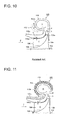
- FIG.10 is a schematic view of a compressor of a turbo charger 100 provided with a resin housing.
- FIG.10 shows an impeller 104 fixed to a rotating shaft 102 and a plurality of blades 106 extending radially from the impeller 104. An outer edge of the blade 106 forms a curved profile 106a.
- a housing 110 is arranged around the blades 106.
- the housing 110 includes a volute section 110a which forms a volute part s and a path forming section 110b which forms a flow path c for the gas to be compressed.
- the path forming section 110b is arranged to surround the blades 106.
- the flow path c is formed by a hub face 108 of the impeller and an inner wall of the path forming section 110b.
- the flow path c curves from an axial direction of the rotating shaft 102 (a direction of an arrow a) into a radial direction of the impeller 104 (a direction of an arrow b).
- the gas to be compressed is drawn into the flow path c in the direction of the arrow a, and reaches the blades 106 to increase an absolute flow velocity of the gas.
- the intake gas whose velocity is increased in the flow path c, is directed into the direction of the arrow b to enter the diffuser d.
- the intake gas advances in the diffuser d, the intake gas is compressed and then exhausted to the volute part s.
- the compressor achieves high compression efficiency with a small clearance T between the inner wall of the path forming section 110b and the curved profile 106a of the impeller 104.
- the temperature of the gas to be compressed is raised by compressing the gas in the compressor.
- the housing 110 made of resin the resin has a higher thermal expansion rate than materials such as metal and thus, the housing 110 expands being exposed to the heat of the gas and thermally deforms in a direction of an arrow e as indicated by a dotted line 110'.
- the clearance T becomes wider and the gas leaks from the wider clearance T, resulting in a decrease in compression efficiency.
- the present invention provides a centrifugal compressor which may include, but is not limited to: an impeller which includes a plurality of blades fixed radially to a rotating shaft; a resin housing which is arranged around the impeller and which is made of resin. Between the impeller and the resin housing, a flow path for a gas to be compressed may be formed by an outer periphery of the impeller and an inner wall of a path forming section of the resin housing, the gas flowing in the flow path from an axial direction to a radial direction of the impeller.
- the inner wall of the path forming section of the resin housing may be carved to form a depression in which an annular shroud is provided, the annular shroud being made of one of a metal and a ceramic material and forming an outer surface of the flow path where the impeller is arranged and an outer surface of a diffuser which is arranged on an outlet side of the flow path.
- the annular shroud may be fixed to a wall facing the annular shroud at the diffuser.
- the inner wall of the path forming section of the resin housing is carved to form the depression in which the annular shroud made of metal or ceramic material is provided.
- the annular shroud forms an outer surface of the flow path where the impeller is arranged and an outer surface of a diffuser which is arranged on an outlet side of the flow path.
- the annular shroud is made of a material which has a higher strength and a lower thermal expansion rate than resin (engineering plastic), such as aluminum and carbon steel, or ceramic.
- the annular shroud is fixed to the wall facing the annular shroud at the diffuser.
- the annular shroud is made separately from the resin housing and is not joined to the inner wall of the resin housing.
- the thermal deformation of the resin housing does not affect the annular shroud, allowing the space between the annular shroud and the curved profile of the impeller to remain the same. Therefore, the compression efficiency is not affected.
- the annular shroud it is not necessary to make the resin housing thicker or to provide a reinforcement rib in the resin housing. As a result, it does not offset merits such as weight saving and cost reduction.
- the centrifugal compressor may be provided with a seal ring housed in a groove which is disposed between a rear face of the annular shroud and the depression of the inner wall of the path forming section.
- the temperature of the gas is low as well as the temperatures of the annular shroud and the inner wall of the path forming section of the resin housing.
- an inexpensive rubber O-ring can be used as the seal ring.
- the diameter of the inlet of the impeller is small and thus, the O-ring of a small diameter can be used. Accordingly, it is possible to achieve the cost reduction of the seal ring.
- the path forming section of the resin housing may be separable at a separating plane into an upstream portion and a downstream portion in a direction of flow of the gas, the separating plane being positioned at the groove for housing the seal ring.
- the resin housing may have a slit in one of the path forming section and a separated part of the path forming section, the split being formed in an axial direction of the rotating shaft and opening to outside.
- a circulation space for the gas may be formed, and at least two communication openings may be formed along a flow direction of the gas such that the communication space and the flow path are in communication with each other through the communication openings to allow the gas to flow in the communication space.
- a portion of the gas enters the communication space through the opening on the downstream side and then returns to the flow path from the opening on the upstream side, thereby forming a circulation flow.
- the circulation flow joins the flow of the gas at the inlet of the impeller, it is possible to keep the flow rate of the gas at the inlet of the impeller not less than a stall limit. As a result, it is possible to lower a lower limit of the flow rate of the compressor.
- the flow rate of the gas when the flow rate of the gas is high, a portion of the gas enters the communication space from the opening on the upstream side and then returns to the flow path from the opening on the downstream side.
- the upper limit of the flow rate of the gas is enhanced.
- the upper limit and the lower limit of the flow rate of the gas which is allowable for operation of the centrifugal compressor, can be expanded.
- the path forming section of the resin housing may be reinforced by an annular reinforcement layer covering an outer wall of the path forming section, the reinforcement layer being made of glass fiber.
- the reinforcement layer made of glass fiber with high tension strength, when the impeller is damaged, the broken pieces of the impeller or the broken impeller does not penetrate through the wall of the path forming section and thus, the wall thickness of the path forming section, reinforced by the reinforcement layer, can be thinner. As a result, it is possible to reduce the production cost of the resin housing.
- the centrifugal compressor is provided with: an impeller which includes a plurality of blades fixed radially to a rotating shaft; a resin housing which is arranged around the impeller and which is made of resin. Between the impeller and the resin housing, a flow path for a gas to be compressed is formed by an outer periphery of the impeller and an inner wall of a path forming section of the resin housing, the gas flowing in the flow path from an axial direction to a radial direction of the impeller.
- the inner wall of the path forming section of the resin housing is carved to form a depression in which an annular shroud is provided, the annular shroud being made of one of a metal and a ceramic material and forming an outer surface of the flow path where the impeller is arranged and an outer surface of a diffuser which is arranged on an outlet side of the flow path.
- the annular shroud is fixed to a wall facing the annular shroud at the diffuser.
- the clearance between the annular shroud and the curved profile of the blade can be kept at a set dimension, thereby maintaining a high compression efficiency, and by providing the annular shroud, there is no need to make the resin housing thicker or to provide a reinforcement rib in the resin housing and thus, the benefits such as a lighter weight or cost reduction of the resin housing can be obtained.
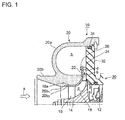
- FIG.1 A first embodiment of a centrifugal compressor to which the present invention is applied is explained in reference to FIG.1 .
- a rotating shaft 12 is arranged in a center of a resin housing 20, and an impeller 14 having a plurality of blades 16 fixed radially is fixed to an outer periphery of the rotating shaft 12.
- a hub face 18 of the impeller 14 curves from an inlet side to an outlet side in a flow direction of a gas to be compressed (a direction indicated with an arrow a) from an axial direction to a radial direction of the rotating shaft 12.
- the resin housing 20 includes a volute section 20a which forms a volute part s and a path forming section 20b which forms a flow path c for the gas to be compressed.
- the outer edge of the blade forms a curved profile 16a.
- an inner wall 20b 1 of the path forming section 20b of the resin housing 20 is formed.
- the inner wall 20b 1 is carved to form a depression 20b 2 in which an annular shroud is inserted.
- the rotating shaft 12 is rotatably and movably supported by a bearing provided in a bearing housing 30.
- the bearing is not shown in the drawing.
- the spiral-shaped volute section 20a forms a volute part s.
- a wall 32 constituting a part of the bearing housing 30 is arranged facing the volute part s formed by the spiral-shaped volute section 20a.
- An end of the volute section 20a is fixed to the wall 32 via a seal ring 34.
- annular shroud 22 In the depression 20b 2 formed in the inner wall 20b 1 of the path forming section 20b, an annular shroud 22 is inserted. A downstream end of the annular shroud 22 which is on a downstream side in a direction of the gas flow, projects into the volute part s. The downstream end of the annular shroud 22 is fixed to the wall 32 by a bolt 26 via a spacer 24.
- the annular shroud 22 is made of a metal which has a higher strength and a lower thermal expansion rate than resin, such as aluminum and carbon steel, or ceramic.
- the annular shroud 22 and the resin housing 20 are not connected. The clearance between the annular shroud 22 and the curved profile 16a of the blade 16 is set as small as possible to maintain decent compression efficiency.
- the annular shroud 22 forms an outer surface of the flow path c and an outer surface of the diffuser d.
- the flow path c directs the gas from an axial direction of the impeller 14 (the direction of the arrow a) into a radial direction of the impeller (a direction of an arrow b).
- the diffuser d is arranged on an outlet side of the flow path c to convert the kinetic energy of the gas into a static pressure.
- An inner surface of the flow path c is formed by the hub face 18 of the impeller 14, whereas an inner surface of the diffuser d is formed by the wall 32.
- the rotation of the impeller 14 causes the gas to be drawn in from an inlet side of the blade 16, through the flow path c and the diffuser d and then converted into the static pressure.
- the compressed gas flows through the diffuser d and then enters the volute part s.
- a plurality of bolts 26 are arranged at intervals in the circumferential direction of the rotating shaft 12. However, the bolts 26 do not interfere with the flow of the gas.
- the annular shroud 22 is fixed to the wall 32 of the bearing housing 30 solely by the bolts 26 and the annular shroud 22 and the resin housing 20 are separated from each other.
- heat deformation of the resin housing 20 does not reach the annular shroud 22. Therefore, even when the resin housing 20 thermally deforms, the clearance between the annular shroud 22 and the blade 16 does not change. As a result, the compression efficiency is not affected.
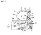
- FIG.2 A second embodiment of the centrifugal compressor to which the present invention is applied is explained in reference to FIG.2 .
- the downstream end 22a of the annular shroud 22 has two bending sections.
- the annular shroud 22 bends at a first bending section to extend to a position where the downstream end comes in contact with the wall 32 of the bearing housing 30 and bends at a second bending section to form a flange part 22a 1 .
- the wall 32 is formed with a depression 32a in which the flange part 22a 1 is fitted.
- the flange part 22a 1 is connected to the depression 32a by a bolt 40.
- the flange part 22a 1 is formed partially around the impeller 14. Thus, the downstream end 22a of the shroud 22 does not block the diffuser d or interfere with the flow of the gas in the diffuser.
- the rest of the structure is substantially the same as that of the first embodiment. The same parts are indicated by the same reference numerals.
- the annular shroud 22 is a single-piece member which extends to the flange part 22a 1 and is processed by pressure forming. Therefore, in addition to the function effects achieved in the first embodiment, the annular shroud 22 is easy to manufacture by pressure-forming and it is easy to connect the annular shroud 22 to the wall 32 as there is no need for the spacer 24 which is provided in the case of the first embodiment, in order to connect the annular shroud 22 to the wall 32.
- a rubber or resin seal ring 50 is inserted.
- the rest of the structure is substantially the same as that of the second embodiment.
- the resin housing 20 thermally deforms, creating a gap between the depression 20b 2 and a rear face of the annular shroud 22, it is possible to prevent the entry of the gas between the depression 20b 2 and the annular shroud 22 by means of the seal ring 50. Therefore, the compression efficiency of the compressor does not decrease.
- the temperature of the gas is approximately the same as the ambient air and is low.
- the temperatures at the annular shroud 22 and the path forming section 20b are also low and thus, an inexpensive rubber O-ring can be used.
- the gas path in which the gas flows does not curve in the radial direction and the diameter of the impeller 14 is small and thus, the O-ring of a small diameter can be used. Therefore, it is possible to achieve the cost reduction of the seal ring 50.
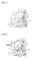
- FIG.4 shows the resin housing 20 of the fourth embodiment.
- the path forming section 20b of the resin housing 20 is separable into two resin separated portions 60 and 62.
- the path forming section 20b is separated into the separated portions 60 and 62 at a separating plane 64 having a stepped portion 64a in a center of a thick-walled portion thereof.
- the separating plane 64 is disposed such that one end there of is positioned at the groove where the seal ring 50 is housed.
- the rest of the structure is substantially the same as that of the third embodiment.
- the path forming section 20b is separated into the separated portions 60 and 62 and thus, the thickness of the path forming section 20b is reduced. This prevents, during molding manufacturing of the resin housing 20, air bubbles from remaining in the path forming section 20b. Therefore, the quality of the resin housing 20 is improved and with improved yield rate, the production cost of the resin housing is reduced. Further, by placing the separating plane 64 to the groove 52, there is no need for carving the path forming section 20b to form the groove 52, and a corner of the separated portion 60 is processed and thus, the molding manufacturing of the separated portion 60 becomes easy, resulting in reducing the processing cost.
- the thick-walled portion of the path forming section 20b of the resin housing 20 has a slit V in a direction perpendicular to the thickness of the path forming section, i.e. in a direction approximately parallel to the rotational axis of the impeller 14.
- the slit V opens to outside.
- the rest of the structure is substantially the same as that of the third embodiment.
- the thick-walled portion of the path forming section 20b can be eliminated. This eliminates air bubbles or the like remaining in the resin housing during injection molding of the resin housing 20. As a result, the quality of the resin housing 20 is improved and the yield is improved, thereby preventing cost increase.
- the separated portion 60 of the separated portions 60 and 62 of the resin housing 20 is formed with a slit Va inside the thick-walled portion of the path forming section 20b.
- the slit Va is formed in the direction perpendicular to the thickness of the path forming section, i.e. in the direction approximately parallel to the rotational axis of the impeller 14. And, an end of the slit Va opens to outside.
- the rest of the structure is substantially the same as that of the fourth embodiment.
- the thick-walled portion of the separated portion 60 is eliminated. This eliminates air bubbles or the like remaining in the resin housing during injection molding of the separated portion 60 of the resin housing 20. As a result, the quality of the separated portion 60 is improved and the yield is improved, thereby preventing cost increase.
- FIG.7 A sixth embodiment in which the present invention is applied to a centrifugal compressor is explained in reference to FIG.7 .
- the inner wall 20b 1 of the path forming section 20b is carved to form the depression 20b 2 in the flow path c and the depression 20b 2 is further carved to form a circulation space 70 on a rear side of the annular shroud 22.
- the annular shroud 22 includes an upstream through-hole 72 and a downstream through-hole 74 where the annular shroud faces the circulation space 70.
- the rest of the structure is substantially the same as that of the second embodiment.
- the sixth embodiment when the flow rate of the gas is low, a portion of the gas flowing in the flow path c enters the circulation space 70 from the downstream through-hole 74 and then returns to the flow path c from the upstream through-hole 72, thereby forming a circulation flow.
- the circulation flow joins the flow of the gas at the inlet of the impeller 14, thereby preventing the impeller 14 from stoll.
- the circulation space 70 is formed on the rear side of the annular shroud 22.
- a circular slit opening 76 is formed between an end of the annular shroud 22 which is on an inlet side and the inner wall 20b 1 of the path forming section 20b.
- the through-hole 74 which is the same as the through-hole 74 of the sixth embodiment, is formed in the annular shroud 22 path c. The rest of the structure is substantially the same as that of the sixth embodiment.
- this modified example has an advantage of easier manufacturing of the annular shroud 22 and the path forming section 20b as the number of through-holes formed in the annular shroud 22 is reduced and there is no need to carve the inner wall surface 20a of the path forming section 20b to form the depression 20b 2 in which the annular shroud 22 is fit. Further, the annular slit opening 76 is formed and thus, the opening area of the slit opening can be increased and it is easy to form the slit opening.
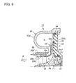
- a seventh embodiment in which the present invention is applied to a centrifugal compressor is explained in reference to FIG.9 .
- the path forming section 20b of the resin housing 20 is made thinner, and behind the path forming section 20b, an annular glass fiberboard 80 is provided.
- the rest of the structure is substantially the same as that of the second embodiment.
- the path forming section 20b When the impeller 14 is damaged, the path forming section 20b must have enough strength to prevent the broken pieces of the impeller or the broken impeller 14 from breaking through the resin housing 20.
- the glass fiberboard 80 is provided on the rear side of the path forming section 20b for reinforcement and thus, the path forming section 20b can be thin. With reduced thickness of the path forming section 20b, it is possible to eliminate air bubbles or the like remaining in the resin housing 20 during injection molding of the resin housing 20. As a result, the quality of the resin housing 20 is improved, thereby improving the yield during the molding manufacturing of the resin housing and preventing cost increase.
Landscapes
- Engineering & Computer Science (AREA)
- Mechanical Engineering (AREA)
- General Engineering & Computer Science (AREA)
- Structures Of Non-Positive Displacement Pumps (AREA)
- Supercharger (AREA)
Abstract
It is intended to provide a centrifugal compressor equipped with a resin housing which does not compression efficiency without offsetting merits such as weight saving and cost reduction. A centrifugal compressor 10 includes a resin housing 20 formed by a volute section 20a and a path forming section 20b. An impeller 14 fixed to a rotating shaft 12 in a center of the path forming section 20b. An annular shroud 22 is arranged in a depression 20b2 carved in an inner wall 20b1 of the path forming section 20b. The annular shroud 22 forms an outer wall of a flow path c for a gas to be compressed and an outer wall of a diffuser d (static-pressure increasing region). A downstream end of the annular shroud 22 is fixed via a spacer 24 to a wall 32 by a bolt 6. The wall 32 constitutes a part of a bearing housing 30. Even when the resin housing 20 thermally deforms, a clearance T between the annular shroud 22 and a curved profile 16a of the blade 16 can be kept at a set dimension.
Description
- The present invention relates to a centrifugal compressor provided with a housing made of resin which is used in a turbocharger or the like.
- A turbocharger installed in a vehicle or the like, drives a compressor by a exhaust turbine which is driven by energy of exhaust gas, compresses intake air in the compressor and supplies the compressed air to an engine. This type of turbocharger is provided with a bearing housing between a turbine housing of the exhaust turbine and a compressor housing for a turbo compressor. The bearing housing movably supports the rotating shaft rotatably. On the rotating shaft arranged through the bearing housing, an impeller of the turbo compressor and a wheel of the exhaust turbine are fixed.
- The bearing housing houses a bearing mechanism for movably supporting the rotating shaft rotatably. Between the bearing housing and the compressor housing, a seal wall is interposed to form a flow path for gas which is enclosed in the compressor housing and is to be compressed.
- A spiral-shaped housing such as a housing for a turbocharger, is normally made of cast aluminum, cast iron or the like. In recent years, for the purposes of making the housing lighter and at lower cost, a housing made of resin is used.
Disclosed in Patent Literature 1, is a housing for a turbo charger, which is made of thermoplastic resin. Disclosed in Patent Literature 2, is a housing for a centrifugal compressor, which has a double-wall structure made of thermoset resin and thermoplastic resin. - Patent Literature 3 discloses the invention to improve compressor efficiency and to prevent an impeller from being damaged. The inner wall of the compressor housing, which faces a flow path of the gas to be compressed, is made of resin material which is highly machinable. A clearance between the inner wall of the compressor housing and a curved profile of the impeller of the compressor is set small to improve compressor efficiency and to prevent the impeller from being damaged when the impeller comes in contact with the inner wall of the compressor housing.
- In Patent Literature 4, an inner wall of a path forming section of a compressor housing of a turbocharger, is made of resin material which is highly machinable so as to reduce a cost thereof.
In Patent Literature 5, for the same reason as Patent Literature 3, an inner wall of a path forming section of a compressor housing of a turbocharger, is made of resin material. -
FIG.10 is a schematic view of a compressor of aturbo charger 100 provided with a resin housing.FIG.10 shows animpeller 104 fixed to arotating shaft 102 and a plurality ofblades 106 extending radially from theimpeller 104. An outer edge of theblade 106 forms acurved profile 106a. Ahousing 110 is arranged around theblades 106. Thehousing 110 includes avolute section 110a which forms a volute part s and apath forming section 110b which forms a flow path c for the gas to be compressed. - The
path forming section 110b is arranged to surround theblades 106. The flow path c is formed by ahub face 108 of the impeller and an inner wall of thepath forming section 110b. The flow path c curves from an axial direction of the rotating shaft 102 (a direction of an arrow a) into a radial direction of the impeller 104 (a direction of an arrow b). A section extending from the flow path c where theblades 106 are arranged to the flow path d which is arranged on an outlet side of the flow path c, functions as a diffuser (static-pressure increasing region). - By rotation of the
impeller 104, the gas to be compressed is drawn into the flow path c in the direction of the arrow a, and reaches theblades 106 to increase an absolute flow velocity of the gas. The intake gas whose velocity is increased in the flow path c, is directed into the direction of the arrow b to enter the diffuser d. As the intake gas advances in the diffuser d, the intake gas is compressed and then exhausted to the volute part s. - The compressor achieves high compression efficiency with a small clearance T between the inner wall of the
path forming section 110b and thecurved profile 106a of theimpeller 104. The temperature of the gas to be compressed is raised by compressing the gas in the compressor. In the case of using thehousing 110 made of resin, the resin has a higher thermal expansion rate than materials such as metal and thus, thehousing 110 expands being exposed to the heat of the gas and thermally deforms in a direction of an arrow e as indicated by a dotted line 110'. By this, the clearance T becomes wider and the gas leaks from the wider clearance T, resulting in a decrease in compression efficiency. - In the resin housing, if the
impeller 104 is damaged and broken pieces thereof fly in the housing, it is necessary to prevent the broken pieces from flying out of the housing. To take measures against the issue, it is possible to increase a thickness of thehousing 110 or to provide a reinforcingrib 112 in thehousing 110. However, such measures offset advantages of using the resin housing from the perspective of weight saving and cost reducing. -
- [PTL 1]
DE 10260042 A1 - [PTL 2]
EP 1830071 A2 - [PTL 3]
JP 9-170442 A - [PTL 4]
JP2001-234753 A - [PTL 5]
JP2002-256878 A - It is an object of the present invention to provide a centrifugal compressor equipped with a resin housing, which can obtain advantages such as a weight saving and cost reduction without decreasing compression efficiency.
- To achieve the above object, the present invention provides a centrifugal compressor which may include, but is not limited to: an impeller which includes a plurality of blades fixed radially to a rotating shaft; a resin housing which is arranged around the impeller and which is made of resin. Between the impeller and the resin housing, a flow path for a gas to be compressed may be formed by an outer periphery of the impeller and an inner wall of a path forming section of the resin housing, the gas flowing in the flow path from an axial direction to a radial direction of the impeller. The inner wall of the path forming section of the resin housing may be carved to form a depression in which an annular shroud is provided, the annular shroud being made of one of a metal and a ceramic material and forming an outer surface of the flow path where the impeller is arranged and an outer surface of a diffuser which is arranged on an outlet side of the flow path. The annular shroud may be fixed to a wall facing the annular shroud at the diffuser.
- According to the present invention, the inner wall of the path forming section of the resin housing is carved to form the depression in which the annular shroud made of metal or ceramic material is provided. The annular shroud forms an outer surface of the flow path where the impeller is arranged and an outer surface of a diffuser which is arranged on an outlet side of the flow path. The annular shroud is made of a material which has a higher strength and a lower thermal expansion rate than resin (engineering plastic), such as aluminum and carbon steel, or ceramic. The annular shroud is fixed to the wall facing the annular shroud at the diffuser.
- The annular shroud is made separately from the resin housing and is not joined to the inner wall of the resin housing. Thus, the thermal deformation of the resin housing does not affect the annular shroud, allowing the space between the annular shroud and the curved profile of the impeller to remain the same. Therefore, the compression efficiency is not affected. With use of the annular shroud, it is not necessary to make the resin housing thicker or to provide a reinforcement rib in the resin housing. As a result, it does not offset merits such as weight saving and cost reduction.
- In the present invention, the centrifugal compressor may be provided with a seal ring housed in a groove which is disposed between a rear face of the annular shroud and the depression of the inner wall of the path forming section. By this, even when the resin housing thermally deforms, leaving a gap between the inner wall of the resin housing and the annular shroud, it is possible to prevent the gas from entering the gap and the gas on the downstream side of the impeller from flowing back to the inlet side of the impeller. As a result, the compression efficiency does not decrease.
- At the inlet of the impeller, the temperature of the gas is low as well as the temperatures of the annular shroud and the inner wall of the path forming section of the resin housing. Thus, an inexpensive rubber O-ring can be used as the seal ring. Further, the diameter of the inlet of the impeller is small and thus, the O-ring of a small diameter can be used. Accordingly, it is possible to achieve the cost reduction of the seal ring.
- In addition to the above structure, the path forming section of the resin housing may be separable at a separating plane into an upstream portion and a downstream portion in a direction of flow of the gas, the separating plane being positioned at the groove for housing the seal ring. By this, it is possible to eliminate a thick-walled portion of the resin housing. This prevents air bubbles or the like remaining in the resin housing during injection molding of the resin housing. As a result, the quality of the resin housing is improved and the yield is improved, thereby preventing cost increase.
Further, by placing the separating plane to the groove for housing the seal ring, there is no need for carving to form the groove and thus, the molding manufacturing of the resin housing becomes easy, resulting in reducing the processing cost. - In the present invention, the resin housing may have a slit in one of the path forming section and a separated part of the path forming section, the split being formed in an axial direction of the rotating shaft and opening to outside. By this, the thick-walled portion of the resin housing can be eliminated. This eliminates air bubbles or the like remaining in the resin housing during injection molding of the resin housing. As a result, the quality of the resin housing is improved and the yield is enhanced, thereby preventing cost increase.
- In the present invention, between the annular shroud and the path forming section of the resin housing, a circulation space for the gas may be formed, and at least two communication openings may be formed along a flow direction of the gas such that the communication space and the flow path are in communication with each other through the communication openings to allow the gas to flow in the communication space. In this manner, when the flow rate of the gas is low, a portion of the gas enters the communication space through the opening on the downstream side and then returns to the flow path from the opening on the upstream side, thereby forming a circulation flow. As the circulation flow joins the flow of the gas at the inlet of the impeller, it is possible to keep the flow rate of the gas at the inlet of the impeller not less than a stall limit. As a result, it is possible to lower a lower limit of the flow rate of the compressor.
- In contrast, when the flow rate of the gas is high, a portion of the gas enters the communication space from the opening on the upstream side and then returns to the flow path from the opening on the downstream side. Thus, the upper limit of the flow rate of the gas is enhanced. As a result, the upper limit and the lower limit of the flow rate of the gas, which is allowable for operation of the centrifugal compressor, can be expanded.
- In the present invention, the path forming section of the resin housing may be reinforced by an annular reinforcement layer covering an outer wall of the path forming section, the reinforcement layer being made of glass fiber. By providing on the outer wall of the path forming section the reinforcement layer made of glass fiber with high tension strength, when the impeller is damaged, the broken pieces of the impeller or the broken impeller does not penetrate through the wall of the path forming section and thus, the wall thickness of the path forming section, reinforced by the reinforcement layer, can be thinner. As a result, it is possible to reduce the production cost of the resin housing.
- According to the centrifugal compressor of the present invention, the centrifugal compressor is provided with: an impeller which includes a plurality of blades fixed radially to a rotating shaft; a resin housing which is arranged around the impeller and which is made of resin. Between the impeller and the resin housing, a flow path for a gas to be compressed is formed by an outer periphery of the impeller and an inner wall of a path forming section of the resin housing, the gas flowing in the flow path from an axial direction to a radial direction of the impeller. The inner wall of the path forming section of the resin housing is carved to form a depression in which an annular shroud is provided, the annular shroud being made of one of a metal and a ceramic material and forming an outer surface of the flow path where the impeller is arranged and an outer surface of a diffuser which is arranged on an outlet side of the flow path. The annular shroud is fixed to a wall facing the annular shroud at the diffuser.
Therefore, the clearance between the annular shroud and the curved profile of the blade can be kept at a set dimension, thereby maintaining a high compression efficiency, and by providing the annular shroud, there is no need to make the resin housing thicker or to provide a reinforcement rib in the resin housing and thus, the benefits such as a lighter weight or cost reduction of the resin housing can be obtained. -
- [
FIG.1] FIG.1 is a side view of a centrifugal compressor in relation to a first embodiment, to which the present invention is applied. - [
FIG.2] FIG.2 is a side view of a centrifugal compressor in relation to a second embodiment, to which the present invention is applied - [
FIG.3] FIG.3 is a side view of a centrifugal compressor in relation to a third embodiment, to which the present invention is applied. - [
FIG.4] FIG.4 is a side view of a centrifugal compressor in relation to a fourth embodiment, to which the present invention is applied. - [
FIG.5] FIG.5 is a side view of a centrifugal compressor in relation to a fifth embodiment, to which the present invention is applied. - [
FIG.6] FIG.6 is a side view showing a modified example of the fifth embodiment. - [
FIG.7] FIG.7 is a side view of a centrifugal compressor in relation to a sixth embodiment, to which the present invention is applied. - [
FIG.8] FIG.8 is a side view showing a modified example of the sixth embodiment. - [
FIG.9] FIG.9 is a side view of a centrifugal compressor in relation to a seventh embodiment, to which the present invention is applied. - [
FIG.10] FIG.10 is a side view showing a part of a conventional centrifugal compressor. - [
FIG.11] FIG.11 is a side view of a centrifugal compressor showing a comparison between a thick resin housing and a reinforcement rib. - An embodiment of the present invention will now be described in detail with reference to the accompanying drawings. It is intended, however, that unless particularly specified, dimensions, materials, shape, its relative positions and the like shall be interpreted as illustrative only and not limitative of the scope of the present invention.
- A first embodiment of a centrifugal compressor to which the present invention is applied is explained in reference to
FIG.1 . InFIG.1 , a rotatingshaft 12 is arranged in a center of aresin housing 20, and animpeller 14 having a plurality ofblades 16 fixed radially is fixed to an outer periphery of therotating shaft 12. Ahub face 18 of theimpeller 14 curves from an inlet side to an outlet side in a flow direction of a gas to be compressed (a direction indicated with an arrow a) from an axial direction to a radial direction of therotating shaft 12. Theresin housing 20 includes avolute section 20a which forms a volute part s and apath forming section 20b which forms a flow path c for the gas to be compressed. - The outer edge of the blade forms a
curved profile 16a. Along thecurved profile 16a, aninner wall 20b1 of thepath forming section 20b of theresin housing 20 is formed. Theinner wall 20b1 is carved to form adepression 20b2 in which an annular shroud is inserted. The rotatingshaft 12 is rotatably and movably supported by a bearing provided in a bearinghousing 30. The bearing is not shown in the drawing. The spiral-shapedvolute section 20a forms a volute part s. Awall 32 constituting a part of the bearinghousing 30 is arranged facing the volute part s formed by the spiral-shapedvolute section 20a. An end of thevolute section 20a is fixed to thewall 32 via aseal ring 34. - In the
depression 20b2 formed in theinner wall 20b1 of thepath forming section 20b, anannular shroud 22 is inserted. A downstream end of theannular shroud 22 which is on a downstream side in a direction of the gas flow, projects into the volute part s. The downstream end of theannular shroud 22 is fixed to thewall 32 by abolt 26 via aspacer 24. Theannular shroud 22 is made of a metal which has a higher strength and a lower thermal expansion rate than resin, such as aluminum and carbon steel, or ceramic. Theannular shroud 22 and theresin housing 20 are not connected. The clearance between theannular shroud 22 and thecurved profile 16a of theblade 16 is set as small as possible to maintain decent compression efficiency. - In this manner, the
annular shroud 22 forms an outer surface of the flow path c and an outer surface of the diffuser d. The flow path c directs the gas from an axial direction of the impeller 14 (the direction of the arrow a) into a radial direction of the impeller (a direction of an arrow b). The diffuser d is arranged on an outlet side of the flow path c to convert the kinetic energy of the gas into a static pressure. An inner surface of the flow path c is formed by thehub face 18 of theimpeller 14, whereas an inner surface of the diffuser d is formed by thewall 32. - With the above structure, the rotation of the
impeller 14 causes the gas to be drawn in from an inlet side of theblade 16, through the flow path c and the diffuser d and then converted into the static pressure. The compressed gas flows through the diffuser d and then enters the volute part s. A plurality ofbolts 26 are arranged at intervals in the circumferential direction of therotating shaft 12. However, thebolts 26 do not interfere with the flow of the gas. - According to the first embodiment, the
annular shroud 22 is fixed to thewall 32 of the bearinghousing 30 solely by thebolts 26 and theannular shroud 22 and theresin housing 20 are separated from each other. Thus, heat deformation of theresin housing 20 does not reach theannular shroud 22. Therefore, even when theresin housing 20 thermally deforms, the clearance between theannular shroud 22 and theblade 16 does not change. As a result, the compression efficiency is not affected. - By providing the
annular shroud 22, it is no longer necessary to make theresin housing 20 thicker or to provide a reinforcement rib or the like in theresin housing 20. As a result, it does not offset merits such as a lighter weight and cost reduction. - A second embodiment of the centrifugal compressor to which the present invention is applied is explained in reference to
FIG.2 . In the second embodiment, as shown inFIG.2 , thedownstream end 22a of theannular shroud 22 has two bending sections. Theannular shroud 22 bends at a first bending section to extend to a position where the downstream end comes in contact with thewall 32 of the bearinghousing 30 and bends at a second bending section to form aflange part 22a1. Thewall 32 is formed with adepression 32a in which theflange part 22a1 is fitted. Theflange part 22a1 is connected to thedepression 32a by abolt 40. - The
flange part 22a1 is formed partially around theimpeller 14. Thus, thedownstream end 22a of theshroud 22 does not block the diffuser d or interfere with the flow of the gas in the diffuser. The rest of the structure is substantially the same as that of the first embodiment. The same parts are indicated by the same reference numerals. - According to the second embodiment, the
annular shroud 22 is a single-piece member which extends to theflange part 22a1 and is processed by pressure forming. Therefore, in addition to the function effects achieved in the first embodiment, theannular shroud 22 is easy to manufacture by pressure-forming and it is easy to connect theannular shroud 22 to thewall 32 as there is no need for thespacer 24 which is provided in the case of the first embodiment, in order to connect theannular shroud 22 to thewall 32. - Next, a third embodiment in which the present invention is applied to a centrifugal compressor is explained in reference to
FIG.3 . In the third embodiment, thedepression 20b2 carved in theinner wall 20b1 of thepath forming section 20b of theresin housing 20, is carved to form agroove 52. In thegroove 52, a rubber orresin seal ring 50 is inserted. The rest of the structure is substantially the same as that of the second embodiment. - According to the third embodiment, even when the
resin housing 20 thermally deforms, creating a gap between thedepression 20b2 and a rear face of theannular shroud 22, it is possible to prevent the entry of the gas between thedepression 20b2 and theannular shroud 22 by means of theseal ring 50. Therefore, the compression efficiency of the compressor does not decrease. - At an inlet of the
impeller 14, the temperature of the gas is approximately the same as the ambient air and is low. At the inlet of the impeller, the temperatures at theannular shroud 22 and thepath forming section 20b are also low and thus, an inexpensive rubber O-ring can be used. Further, at the inlet of theimpeller 14, the gas path in which the gas flows does not curve in the radial direction and the diameter of theimpeller 14 is small and thus, the O-ring of a small diameter can be used. Therefore, it is possible to achieve the cost reduction of theseal ring 50. - Next, a fourth embodiment in which the present invention is applied to a centrifugal compressor is explained in reference to
FIG.4. FIG.4 shows theresin housing 20 of the fourth embodiment. Thepath forming section 20b of theresin housing 20 is separable into two resin separatedportions path forming section 20b is separated into the separatedportions plane 64 having a steppedportion 64a in a center of a thick-walled portion thereof. The separatingplane 64 is disposed such that one end there of is positioned at the groove where theseal ring 50 is housed. The rest of the structure is substantially the same as that of the third embodiment. - According to the fourth embodiment, the
path forming section 20b is separated into the separatedportions path forming section 20b is reduced. This prevents, during molding manufacturing of theresin housing 20, air bubbles from remaining in thepath forming section 20b. Therefore, the quality of theresin housing 20 is improved and with improved yield rate, the production cost of the resin housing is reduced.
Further, by placing the separatingplane 64 to thegroove 52, there is no need for carving thepath forming section 20b to form thegroove 52, and a corner of the separatedportion 60 is processed and thus, the molding manufacturing of the separatedportion 60 becomes easy, resulting in reducing the processing cost. - Next, a fifth embodiment in which the present invention is applied to a centrifugal compressor is explained in reference to
FIG.5 . In the fifth embodiment, the thick-walled portion of thepath forming section 20b of theresin housing 20, has a slit V in a direction perpendicular to the thickness of the path forming section, i.e. in a direction approximately parallel to the rotational axis of theimpeller 14. The slit V opens to outside. The rest of the structure is substantially the same as that of the third embodiment. - According to the fifth embodiment, by forming the slit V in the
path forming section 20b, the thick-walled portion of thepath forming section 20b can be eliminated. This eliminates air bubbles or the like remaining in the resin housing during injection molding of theresin housing 20. As a result, the quality of theresin housing 20 is improved and the yield is improved, thereby preventing cost increase. - A modified example of the fifth preferred embodiment is explained in reference to
FIG.6 . According to the modified example shown inFIG.6 , the separatedportion 60 of the separatedportions resin housing 20, is formed with a slit Va inside the thick-walled portion of thepath forming section 20b. The slit Va is formed in the direction perpendicular to the thickness of the path forming section, i.e. in the direction approximately parallel to the rotational axis of theimpeller 14. And, an end of the slit Va opens to outside. The rest of the structure is substantially the same as that of the fourth embodiment. - According to the modified example, in addition to the function effects achieved in the fourth embodiment, by providing the slit Va in the
path forming section 20b of the separatedportion 60, the thick-walled portion of the separatedportion 60 is eliminated. This eliminates air bubbles or the like remaining in the resin housing during injection molding of the separatedportion 60 of theresin housing 20. As a result, the quality of the separatedportion 60 is improved and the yield is improved, thereby preventing cost increase. - A sixth embodiment in which the present invention is applied to a centrifugal compressor is explained in reference to
FIG.7 . In the sixth embodiment, theinner wall 20b1 of thepath forming section 20b is carved to form thedepression 20b2 in the flow path c and thedepression 20b2 is further carved to form acirculation space 70 on a rear side of theannular shroud 22. Theannular shroud 22 includes an upstream through-hole 72 and a downstream through-hole 74 where the annular shroud faces thecirculation space 70. The rest of the structure is substantially the same as that of the second embodiment. - According to the sixth embodiment, when the flow rate of the gas is low, a portion of the gas flowing in the flow path c enters the
circulation space 70 from the downstream through-hole 74 and then returns to the flow path c from the upstream through-hole 72, thereby forming a circulation flow. As the circulation flow joins the flow of the gas at the inlet of theimpeller 14, thereby preventing theimpeller 14 from stoll. As a result, it is possible to lower a lower limit of the flow rate of the compressor. - In contrast, when the flow rate of the gas is high, a portion of the gas flowing in the flow path c enters the
circulation space 70 from the upstream through-hole 72 and then returns to the flow path c from the downstream through-hole 74. By this, it is possible to increase an upper limit of the flow rate of the gas. As a result, the range of the flow rate of the gas, which is allowable for operation of the centrifugal compressor, can be expanded. - Next, a modified example of the sixth embodiment is explained in reference to
FIG.8 . In a manner similar to the sixth embodiment, thecirculation space 70 is formed on the rear side of theannular shroud 22. At the entrance to the flow path c, a circular slit opening 76 is formed between an end of theannular shroud 22 which is on an inlet side and theinner wall 20b1 of thepath forming section 20b. On a downstream side of the slit opening 76, the through-hole 74 which is the same as the through-hole 74 of the sixth embodiment, is formed in theannular shroud 22 path c. The rest of the structure is substantially the same as that of the sixth embodiment. - In comparison with the sixth embodiment, this modified example has an advantage of easier manufacturing of the
annular shroud 22 and thepath forming section 20b as the number of through-holes formed in theannular shroud 22 is reduced and there is no need to carve theinner wall surface 20a of thepath forming section 20b to form thedepression 20b2 in which theannular shroud 22 is fit. Further, the annular slit opening 76 is formed and thus, the opening area of the slit opening can be increased and it is easy to form the slit opening. - A seventh embodiment in which the present invention is applied to a centrifugal compressor is explained in reference to
FIG.9 . In the seventh embodiment, thepath forming section 20b of theresin housing 20 is made thinner, and behind thepath forming section 20b, anannular glass fiberboard 80 is provided. The rest of the structure is substantially the same as that of the second embodiment. - When the
impeller 14 is damaged, thepath forming section 20b must have enough strength to prevent the broken pieces of the impeller or thebroken impeller 14 from breaking through theresin housing 20. According to the seventh embodiment, theglass fiberboard 80 is provided on the rear side of thepath forming section 20b for reinforcement and thus, thepath forming section 20b can be thin. With reduced thickness of thepath forming section 20b, it is possible to eliminate air bubbles or the like remaining in theresin housing 20 during injection molding of theresin housing 20. As a result, the quality of theresin housing 20 is improved, thereby improving the yield during the molding manufacturing of the resin housing and preventing cost increase. - According to the present invention, it is possible, in a centrifugal compressor which can be used in a turbocharger or the like, to achieve a lighter weight and cost reduction of the housing without a decrease in compression efficiency even when the housing is thermally deformed.
Claims (6)
- A centrifugal compressor comprising:an impeller which comprises a plurality of blades fixed radially to a rotating shaft; anda resin housing which is arranged around the impeller and which is made of resin,wherein between the impeller and the resin housing, a flow path for a gas to be compressed is formed by an outer periphery of the impeller and an inner wall of a path forming section of the resin housing, the gas flowing in the flow path from an axial direction to a radial direction of the impeller,wherein the inner wall of the path forming section of the resin housing is carved to form a depression in which an annular shroud is provided, the annular shroud being made of one of a metal and a ceramic material and forming an outer surface of the flow path where the impeller is arranged and an outer surface of a diffuser which is arranged on an outlet side of the flow path, andwherein the annular shroud is fixed to a wall facing the annular shroud at the diffuser.
- The centrifugal compressor according to claim 1, further comprising:a seal ring housed in a groove which is disposed between a rear face of the annular shroud and the depression of the inner wall of the path forming section.
- The centrifugal compressor according to claim 2,
wherein the path forming section of the resin housing is separable at a separating plane into an upstream portion and a downstream portion in a direction of flow of the gas, the separating plane being positioned at the groove for housing the seal ring. - The centrifugal compressor according to any one of claims 1 to 3,
wherein the resin housing has a slit in one of the path forming section and a separated part of the path forming section, the split being formed in an axial direction of the rotating shaft and opening to outside. - The centrifugal compressor according to claim 1,
wherein between the annular shroud and the path forming section of the resin housing, a circulation space for the gas is formed, and at least two communication openings are formed along a flow direction of the gas such that the communication space and the flow path are in communication with each other through the communication openings to allow the gas to flow in the communication space. - The centrifugal compressor according to claim 1,
wherein the path forming section of the resin housing is reinforced by an annular reinforcement layer covering an outer wall of the path forming section, the reinforcement layer being made of glass fiber.
Applications Claiming Priority (2)
| Application Number | Priority Date | Filing Date | Title |
|---|---|---|---|
| JP2009215082A JP2011064118A (en) | 2009-09-16 | 2009-09-16 | Centrifugal compressor |
| PCT/JP2010/054505 WO2011033800A1 (en) | 2009-09-16 | 2010-03-17 | Centrifugal compressor |
Publications (1)
| Publication Number | Publication Date |
|---|---|
| EP2441965A1 true EP2441965A1 (en) | 2012-04-18 |
Family
ID=43758414
Family Applications (1)
| Application Number | Title | Priority Date | Filing Date |
|---|---|---|---|
| EP10816914A Withdrawn EP2441965A1 (en) | 2009-09-16 | 2010-03-17 | Centrifugal compressor |
Country Status (6)
| Country | Link |
|---|---|
| US (1) | US20120148391A1 (en) |
| EP (1) | EP2441965A1 (en) |
| JP (1) | JP2011064118A (en) |
| KR (1) | KR20120013458A (en) |
| CN (1) | CN102472296A (en) |
| WO (1) | WO2011033800A1 (en) |
Cited By (1)
| Publication number | Priority date | Publication date | Assignee | Title |
|---|---|---|---|---|
| US9200639B2 (en) | 2012-08-19 | 2015-12-01 | Honeywell International Inc. | Compressor housing assembly |
Families Citing this family (26)
| Publication number | Priority date | Publication date | Assignee | Title |
|---|---|---|---|---|
| GB2504415B (en) | 2011-08-26 | 2014-08-13 | Dyson Technology Ltd | Turbomachine |
| GB2493973B (en) * | 2011-08-26 | 2015-04-15 | Dyson Technology Ltd | Rotor assembly for a turbomachine |
| GB2493975B (en) | 2011-08-26 | 2015-02-11 | Dyson Technology Ltd | Turbomachine |
| GB2493972B (en) | 2011-08-26 | 2014-12-03 | Dyson Technology Ltd | Rotor assembly for a turbomachine |
| DE102012211375A1 (en) * | 2012-06-29 | 2014-04-10 | Bayerische Motoren Werke Aktiengesellschaft | turbocharger |
| CN102996520A (en) * | 2012-12-27 | 2013-03-27 | 中国航空工业集团公司金城南京机电液压工程研究中心 | Housing structure of centrifugal compressor |
| DE102014204768A1 (en) * | 2013-05-16 | 2014-11-20 | Bosch Mahle Turbo Systems Gmbh & Co. Kg | Radial compressor for an exhaust gas turbocharger |
| KR101537061B1 (en) * | 2013-06-10 | 2015-07-15 | 정현욱 | Motor and turbo compressor with the same |
| CN106662118B (en) | 2014-07-02 | 2019-05-28 | 三菱重工业株式会社 | compressor |
| KR101634876B1 (en) * | 2014-12-02 | 2016-06-30 | 한국기계연구원 | Micro gas turbine with damage prevention structure by thermal stress |
| JP6288516B2 (en) * | 2014-12-03 | 2018-03-07 | 三菱重工業株式会社 | Impeller and rotating machine |
| JP6270280B2 (en) | 2014-12-03 | 2018-01-31 | 三菱重工業株式会社 | Impeller and rotating machine |
| JP6204398B2 (en) * | 2015-03-23 | 2017-09-27 | カルソニックカンセイ株式会社 | Turbine housing |
| US10400790B2 (en) | 2015-05-21 | 2019-09-03 | Mitsubishi Heavy Industries Compressor Corporation | Compressor |
| US10519806B2 (en) * | 2015-11-06 | 2019-12-31 | Calsonic Kansei Corporation | Turbine housing |
| CN109996966A (en) | 2016-12-14 | 2019-07-09 | 开利公司 | Two-stage centrifugal compressor |
| JP7164346B2 (en) * | 2018-07-24 | 2022-11-01 | 三菱重工マリンマシナリ株式会社 | Rotating machines and turbochargers |
| JP2020023917A (en) * | 2018-08-07 | 2020-02-13 | 株式会社オティックス | Compressor housing for supercharger |
| DE102018128255A1 (en) * | 2018-11-12 | 2020-05-14 | Ebm-Papst Landshut Gmbh | Blower device |
| EP3904697A1 (en) * | 2020-04-29 | 2021-11-03 | ABB Schweiz AG | Noise damper for a turbocharger of a combustion engine |
| DE112022000182T5 (en) * | 2021-02-09 | 2023-09-14 | Ihi Corporation | Rotary machine |
| US11519423B1 (en) * | 2021-11-11 | 2022-12-06 | Progress Rail Locomotive Inc. | Compressor joint |
| JP7622618B2 (en) * | 2021-11-30 | 2025-01-28 | 株式会社豊田自動織機 | Turbo Fluid Machinery |
| US12421859B2 (en) | 2023-02-01 | 2025-09-23 | Hamilton Sundstrand Corporation | Metal plated additively manufactured plastic seal plates and their method of manufacturing |
| US12179425B2 (en) * | 2023-02-01 | 2024-12-31 | Hamilton Sundstrand Corporation | Metal plated additively manufactured plastic rotor shrouds and their method of manufacturing |
| US12571421B2 (en) | 2023-02-01 | 2026-03-10 | Hamilton Sundstrand Corporation | Metal plated additively manufactured plastic shafts and their method of manufacturing |
Family Cites Families (12)
| Publication number | Priority date | Publication date | Assignee | Title |
|---|---|---|---|---|
| JPS6179900A (en) * | 1984-09-28 | 1986-04-23 | Nissan Motor Co Ltd | Compressor housing |
| JPH04125633U (en) * | 1991-05-01 | 1992-11-16 | 石川島播磨重工業株式会社 | Turbocharger compressor casing |
| JP4031062B2 (en) * | 1995-08-11 | 2008-01-09 | 株式会社荏原製作所 | Plastic parts and manufacturing method thereof |
| JP3294491B2 (en) * | 1995-12-20 | 2002-06-24 | 株式会社日立製作所 | Turbocharger for internal combustion engine |
| JP2001234753A (en) | 2000-02-24 | 2001-08-31 | Hitachi Ltd | Compressor housing for turbocharger |
| JP2001317492A (en) * | 2000-05-02 | 2001-11-16 | Honda Motor Co Ltd | Centrifugal compressor and jet engine using the same |
| JP2002256878A (en) | 2002-01-28 | 2002-09-11 | Hitachi Ltd | Wall member used for supercharger of internal combustion engine |
| JP2003322026A (en) * | 2002-04-30 | 2003-11-14 | Shinano Kenshi Co Ltd | Supercharger |
| JP4321037B2 (en) * | 2002-10-25 | 2009-08-26 | 株式会社豊田中央研究所 | Centrifugal compressor for turbocharger |
| DE10260042A1 (en) | 2002-12-19 | 2004-07-08 | Volkswagen Ag | Automotive exhaust system turbocharger housing fabricated of heat-hardened plastic with a compressor front section and an interior helical contour |
| JP3877211B2 (en) * | 2003-03-20 | 2007-02-07 | 株式会社イワキ | Manufacturing method of rear casing in magnet pump |
| DE102006010461B3 (en) * | 2006-03-03 | 2007-10-25 | Woco Industrietechnik Gmbh | Plastic compressor housing |
-
2009
- 2009-09-16 JP JP2009215082A patent/JP2011064118A/en active Pending
-
2010
- 2010-03-17 WO PCT/JP2010/054505 patent/WO2011033800A1/en not_active Ceased
- 2010-03-17 CN CN2010800292137A patent/CN102472296A/en active Pending
- 2010-03-17 EP EP10816914A patent/EP2441965A1/en not_active Withdrawn
- 2010-03-17 US US13/380,649 patent/US20120148391A1/en not_active Abandoned
- 2010-03-17 KR KR1020117031275A patent/KR20120013458A/en not_active Ceased
Non-Patent Citations (1)
| Title |
|---|
| See references of WO2011033800A1 * |
Cited By (1)
| Publication number | Priority date | Publication date | Assignee | Title |
|---|---|---|---|---|
| US9200639B2 (en) | 2012-08-19 | 2015-12-01 | Honeywell International Inc. | Compressor housing assembly |
Also Published As
| Publication number | Publication date |
|---|---|
| CN102472296A (en) | 2012-05-23 |
| KR20120013458A (en) | 2012-02-14 |
| JP2011064118A (en) | 2011-03-31 |
| WO2011033800A1 (en) | 2011-03-24 |
| US20120148391A1 (en) | 2012-06-14 |
Similar Documents
| Publication | Publication Date | Title |
|---|---|---|
| US20120148391A1 (en) | Centrifugal compressor | |
| JP4275081B2 (en) | Scroll structure of variable displacement exhaust turbocharger and method of manufacturing the same | |
| JP5767636B2 (en) | Vacuum pump | |
| US20130251531A1 (en) | Rotary machine | |
| KR20080063131A (en) | Guide vanes and methods of manufacturing the same | |
| US20150192140A1 (en) | Composite Housing with a Metallic Flange for the Compressor of an Axial Turbomachine | |
| CN102317634A (en) | Axial turbocompressors for gas turbines with low radial clearance losses and diffuser losses | |
| US10156243B2 (en) | Composite splitter lip for axial turbomachine compressor | |
| EP3144541B1 (en) | Compressor | |
| EP3228871B1 (en) | Impeller and rotary machine | |
| EP3211241A1 (en) | Impeller and rotary machine | |
| CN110273714B (en) | Collar support assembly for an airfoil | |
| KR20090035599A (en) | Turbine housing | |
| US20160069207A1 (en) | Fan disk for a jet engine and jet engine | |
| JP2012057592A (en) | Fixed vane type turbocharger | |
| KR101522099B1 (en) | Exhaust gas turbocharger | |
| CN107725479B (en) | A kind of rotor casing structure inside inside rotating disc cavities and the engine comprising the structure | |
| EP2657481B1 (en) | Scroll portion structure for radial turbine or diagonal flow turbine | |
| EP2292908B1 (en) | Turbocharger with axial discontinuity | |
| US11885338B2 (en) | Housing for a centrifugal compressor | |
| KR101629524B1 (en) | A turbine engine compressor cover having an axial abutment | |
| US12553355B2 (en) | Nozzle ring for a radial turbine, exhaust turbine, and turbocharger | |
| US10598188B2 (en) | Radial compressor and turbocharger | |
| US20250369365A1 (en) | Turbine engine motor having an unducted fan | |
| US20240117811A1 (en) | Impeller preloading bands |
Legal Events
| Date | Code | Title | Description |
|---|---|---|---|
| PUAI | Public reference made under article 153(3) epc to a published international application that has entered the european phase |
Free format text: ORIGINAL CODE: 0009012 |
|
| 17P | Request for examination filed |
Effective date: 20120112 |
|
| AK | Designated contracting states |
Kind code of ref document: A1 Designated state(s): AT BE BG CH CY CZ DE DK EE ES FI FR GB GR HR HU IE IS IT LI LT LU LV MC MK MT NL NO PL PT RO SE SI SK SM TR |
|
| DAX | Request for extension of the european patent (deleted) | ||
| STAA | Information on the status of an ep patent application or granted ep patent |
Free format text: STATUS: THE APPLICATION HAS BEEN WITHDRAWN |
|
| 18W | Application withdrawn |
Effective date: 20130426 |