EP2441920A2 - Turbine rotor assembly - Google Patents
Turbine rotor assembly Download PDFInfo
- Publication number
- EP2441920A2 EP2441920A2 EP11184232A EP11184232A EP2441920A2 EP 2441920 A2 EP2441920 A2 EP 2441920A2 EP 11184232 A EP11184232 A EP 11184232A EP 11184232 A EP11184232 A EP 11184232A EP 2441920 A2 EP2441920 A2 EP 2441920A2
- Authority
- EP
- European Patent Office
- Prior art keywords
- platform
- blade
- airfoil
- side edge
- root
- Prior art date
- Legal status (The legal status is an assumption and is not a legal conclusion. Google has not performed a legal analysis and makes no representation as to the accuracy of the status listed.)
- Granted
Links
- 238000001816 cooling Methods 0.000 claims abstract description 107
- 238000007789 sealing Methods 0.000 claims description 14
- 238000004891 communication Methods 0.000 description 3
- 230000000712 assembly Effects 0.000 description 2
- 238000000429 assembly Methods 0.000 description 2
- 230000002411 adverse Effects 0.000 description 1
- 230000000740 bleeding effect Effects 0.000 description 1
- 230000001010 compromised effect Effects 0.000 description 1
- 230000008878 coupling Effects 0.000 description 1
- 238000010168 coupling process Methods 0.000 description 1
- 238000005859 coupling reaction Methods 0.000 description 1
- 230000000994 depressogenic effect Effects 0.000 description 1
- 238000011068 loading method Methods 0.000 description 1
- 238000011144 upstream manufacturing Methods 0.000 description 1
Images


Classifications
-
- F—MECHANICAL ENGINEERING; LIGHTING; HEATING; WEAPONS; BLASTING
- F01—MACHINES OR ENGINES IN GENERAL; ENGINE PLANTS IN GENERAL; STEAM ENGINES
- F01D—NON-POSITIVE DISPLACEMENT MACHINES OR ENGINES, e.g. STEAM TURBINES
- F01D5/00—Blades; Blade-carrying members; Heating, heat-insulating, cooling or antivibration means on the blades or the members
- F01D5/30—Fixing blades to rotors; Blade roots ; Blade spacers
- F01D5/3007—Fixing blades to rotors; Blade roots ; Blade spacers of axial insertion type
- F01D5/3015—Fixing blades to rotors; Blade roots ; Blade spacers of axial insertion type with side plates
-
- F—MECHANICAL ENGINEERING; LIGHTING; HEATING; WEAPONS; BLASTING
- F01—MACHINES OR ENGINES IN GENERAL; ENGINE PLANTS IN GENERAL; STEAM ENGINES
- F01D—NON-POSITIVE DISPLACEMENT MACHINES OR ENGINES, e.g. STEAM TURBINES
- F01D5/00—Blades; Blade-carrying members; Heating, heat-insulating, cooling or antivibration means on the blades or the members
- F01D5/02—Blade-carrying members, e.g. rotors
- F01D5/08—Heating, heat-insulating or cooling means
- F01D5/081—Cooling fluid being directed on the side of the rotor disc or at the roots of the blades
- F01D5/082—Cooling fluid being directed on the side of the rotor disc or at the roots of the blades on the side of the rotor disc
-
- F—MECHANICAL ENGINEERING; LIGHTING; HEATING; WEAPONS; BLASTING
- F05—INDEXING SCHEMES RELATING TO ENGINES OR PUMPS IN VARIOUS SUBCLASSES OF CLASSES F01-F04
- F05D—INDEXING SCHEME FOR ASPECTS RELATING TO NON-POSITIVE-DISPLACEMENT MACHINES OR ENGINES, GAS-TURBINES OR JET-PROPULSION PLANTS
- F05D2240/00—Components
- F05D2240/80—Platforms for stationary or moving blades
- F05D2240/81—Cooled platforms
-
- F—MECHANICAL ENGINEERING; LIGHTING; HEATING; WEAPONS; BLASTING
- F05—INDEXING SCHEMES RELATING TO ENGINES OR PUMPS IN VARIOUS SUBCLASSES OF CLASSES F01-F04
- F05D—INDEXING SCHEME FOR ASPECTS RELATING TO NON-POSITIVE-DISPLACEMENT MACHINES OR ENGINES, GAS-TURBINES OR JET-PROPULSION PLANTS
- F05D2260/00—Function
- F05D2260/20—Heat transfer, e.g. cooling
- F05D2260/201—Heat transfer, e.g. cooling by impingement of a fluid
-
- F—MECHANICAL ENGINEERING; LIGHTING; HEATING; WEAPONS; BLASTING
- F05—INDEXING SCHEMES RELATING TO ENGINES OR PUMPS IN VARIOUS SUBCLASSES OF CLASSES F01-F04
- F05D—INDEXING SCHEME FOR ASPECTS RELATING TO NON-POSITIVE-DISPLACEMENT MACHINES OR ENGINES, GAS-TURBINES OR JET-PROPULSION PLANTS
- F05D2260/00—Function
- F05D2260/20—Heat transfer, e.g. cooling
- F05D2260/202—Heat transfer, e.g. cooling by film cooling
-
- F—MECHANICAL ENGINEERING; LIGHTING; HEATING; WEAPONS; BLASTING
- F05—INDEXING SCHEMES RELATING TO ENGINES OR PUMPS IN VARIOUS SUBCLASSES OF CLASSES F01-F04
- F05D—INDEXING SCHEME FOR ASPECTS RELATING TO NON-POSITIVE-DISPLACEMENT MACHINES OR ENGINES, GAS-TURBINES OR JET-PROPULSION PLANTS
- F05D2260/00—Function
- F05D2260/20—Heat transfer, e.g. cooling
- F05D2260/204—Heat transfer, e.g. cooling by the use of microcircuits
-
- Y—GENERAL TAGGING OF NEW TECHNOLOGICAL DEVELOPMENTS; GENERAL TAGGING OF CROSS-SECTIONAL TECHNOLOGIES SPANNING OVER SEVERAL SECTIONS OF THE IPC; TECHNICAL SUBJECTS COVERED BY FORMER USPC CROSS-REFERENCE ART COLLECTIONS [XRACs] AND DIGESTS
- Y02—TECHNOLOGIES OR APPLICATIONS FOR MITIGATION OR ADAPTATION AGAINST CLIMATE CHANGE
- Y02T—CLIMATE CHANGE MITIGATION TECHNOLOGIES RELATED TO TRANSPORTATION
- Y02T50/00—Aeronautics or air transport
- Y02T50/60—Efficient propulsion technologies, e.g. for aircraft
Definitions
- the inventive subject matter described herein generally relates to turbine rotor assemblies, and more particularly relates to turbine blades for use in turbine rotor assemblies.
- Gas turbine engines such as turbofan gas turbine engines, may be used to power various types of vehicles and systems, such as, for example, aircraft.
- these engines include turbine blades that are impinged on by high-energy compressed air that causes a turbine of the engine to rotate at a high speed. Consequently, the blades are subjected to high heat and stress loadings which, over time, may reduce their structural integrity.
- a blade cooling scheme is typically incorporated into the turbines.
- the blade cooling scheme directs cooling air through an internal cooling circuit formed in the blade to maintain blade temperatures within acceptable limits.
- the internal cooling circuit may include a simple channel extending through a length of the blade or may consist of a series of connected, serpentine cooling passages, which incorporate raised or depressed structures therein.
- the serpentine cooling passages increase the cooling effectiveness by extending the length of the air flow path.
- the blade may have multiple internal walls that form the intricate cooling passages through which the cooling air flows. The cooling passages then direct the cooling air to openings on a tip and a trailing edge of the blade.
- engine components are increasingly being subjected to higher and higher operating temperatures.
- newer engine designs may employ operating temperatures that are about 150° C higher than conventional operating temperatures.
- current engine components such as the blades, may not be as efficiently designed as desired.
- certain portions of the blade such as a platform of the blade, draw cooling air from the internal cooling circuit.
- bleeding cooling air from the internal cooling circuit can increase pressure loss.
- platform cooling may be adversely affected.
- a turbine rotor assembly includes a rotor, a blade extending from the rotor, and a seal plate.
- the blade includes an airfoil defined by a convex suction side wall, a concave pressure side wall, a leading edge, a trailing edge, a root, and a tip, the walls and the tip each including an interior surface that defines an interior with the root, the interior including an airfoil cooling circuit for directing airflow through the blade, and a platform supporting the airfoil and having a leading side edge, a trailing side edge, suction side edge, a pressure side edge, an airfoil-facing wall, and a root-facing wall, the platform including a platform cooling circuit having an inlet on the leading side edge and an outlet.
- the seal plate is disposed adjacent to the rotor to form a cool air cavity for directing cool air to the cooling hole.
- a turbine blade in another embodiment, by way of example only, includes an airfoil defined by a convex suction side wall, a concave pressure side wall, a leading edge, a trailing edge, a root, and a tip, the walls and the tip each including an interior surface that defines an interior with the root, the interior including an airfoil cooling circuit for directing airflow through the blade, and a platform supporting the airfoil and having a leading side edge, a trailing side edge, suction side edge, a pressure side edge, an airfoil-facing wall, and a root-facing wall, the platform including a platform cooling circuit having an inlet on the leading side edge and an outlet.
- a turbine rotor assembly includes a rotor, a blade extending from the rotor, and a seal plate.
- the blade includes an airfoil defined by a convex suction side wall, a concave pressure side wall, a leading edge, a trailing edge, a root, and a tip, the walls and the tip each including an interior surface that defines an interior with the root, the interior including an airfoil cooling circuit for directing airflow through the blade, and a platform supporting the airfoil and having a leading side edge, a trailing side edge, suction side edge, a pressure side edge, an airfoil-facing wall, and a root-facing wall, the platform including a platform cooling circuit having a cooling air supply hole on the leading side edge of the platform, an inlet on the root-facing wall, and an outlet.
- the seal plate is disposed adjacent to the rotor to form a cool air cavity for directing cool air to the cooling hole.
- FIG. 1 is a partial cross-sectional side view of a high pressure turbine stage of an engine, according to an embodiment
- FIG. 2 close-up view of a portion of a turbine rotor assembly including a blade having a cooling system, according to an embodiment
- FIG. 3 is a reverse image of a top view of a blade including a platform cooling circuit; according to an embodiment
- FIG. 4 is a reverse image of a top view of a blade including a platform cooling circuit; according to another embodiment
- FIG. 5 is a close-up view of a portion of a turbine rotor assembly including a platform cooling circuit, according to an embodiment
- FIG. 6 is a close-up view of a portion of a turbine rotor assembly including a platform cooling circuit, according to another embodiment
- FIG. 7 is a close-up view of a portion of a turbine rotor assembly including a platform cooling circuit, according to still another embodiment.
- FIG. 8 is a cross section view of two adjacent blades, according to an embodiment.
- the blade includes an airfoil defined by a convex suction side wall, a concave pressure side wall, a leading edge, a trailing edge, a root, and a tip, the walls and the tip each including an interior surface that defines an interior with the root, the interior including an airfoil cooling circuit for directing airflow through the blade, and a platform supporting the airfoil and having a leading side edge, a trailing side edge, suction side edge, a pressure side edge, an airfoil-facing wall, and a root-facing wall, the platform including a platform cooling circuit having an inlet on the leading side edge and an outlet.
- the outlet can be formed on one or more of the airfoil-facing wall, the pressure side edge, the suction side edge, and/or the trailing side edge.
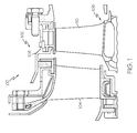
- FIG. 1 is a partial cross-sectional side view of a high pressure turbine stage 102 of an engine 100, according to an embodiment.
- the high pressure turbine stage 102 includes a turbine stator 104 and a turbine rotor assembly 106, both surrounded by a shroud 108 defining a gas flow path through which hot, combusted air from an upstream compressor section (not shown) is directed.
- the turbine stator 104 directs the air toward the turbine rotor assembly 106.
- the air impinges upon blades 110 of the turbine rotor assembly 106, causing the turbine rotor assembly 106 to rotate.
- FIG. 2 is a close-up view of a portion of a turbine rotor assembly 200 including a blade 202 having a cooling system, according to an embodiment.
- the turbine rotor assembly 200 includes a forward seal plate 204, a turbine disk 206, blades 202 (only one of which is shown), and an aft seal plate 205, in an embodiment.
- the forward seal plate 204 is spaced apart from the turbine disk 206 to form a flow cavity 208.
- the flow cavity 208 is configured to be in flow communication with a cool air source (e.g., a compressor section, not shown).
- a cool air source e.g., a compressor section, not shown.
- An annular sealing flange 214 divides the flow cavity 208 into an inner radial cavity 210 and an outer radial cavity 212.
- the annular sealing flange 214 extends axially from the forward seal plate 204 and is configured to seal against a root 216 of a corresponding blade 202 in the turbine disk 206.
- the annular sealing flange 214 is disposed radially inward from an outer diameter 217 of the forward seal plate 204.
- the annular sealing flange 214 has a relatively flat sealing surface 220 for contacting the blade 202.
- the sealing flange 214 can include a sealing ring 218 formed in a suitably located groove 222 in the annular sealing flange 214 to improve sealing.
- the cool air from the flow cavity 208 is directed to the blade 202 to cool the blade 202.
- the blade 202 includes an airfoil 230, a platform 232, and the root 216.
- the airfoil 230 is disposed over the platform 232, which includes a platform cooling circuit 234 formed therein.
- the platform cooling circuit 234 has an inlet 236 for receiving the cool air and channels 238 (one of which is depicted) for flowing the cool air through the platform 232.
- the inlet 236 is formed on a leading side edge wall of the platform 228.
- a delivery channel 240 is formed through the forward seal plate 204.
- the delivery channel 240 extends behind the groove 222 of the forward seal plate 204.
- the delivery channel 240' is formed through the root 216, which is disposed in a blade slot 248 of the turbine disk 206. Because an inner radial surface 242 of the root 216 is spaced apart from the surface defining the blade slot 248 to form a flow channel 244, the delivery channel 240' can extend from the flow channel 244 to a leading side wall 246 of the root 216 and to flow cool air from the flow channel 244 into the outer radial cavity 212.
- a single delivery channel 240 is included in FIG. 2
- a plurality of delivery channels 240 can be included at various locations around the annular sealing flange 214, in other embodiments. In such embodiments, the delivery channels 240 may be substantially evenly spaced around the annular sealing flange 214 or unevenly spaced.
- FIG. 3 is a reverse image of a top view of a blade 300 including a platform cooling circuit 302 and an internal cooling circuit 326, according to an embodiment.
- the blade 300 includes an airfoil 304 and a platform 306.
- the airfoil 304 is generally made up of a concave, pressure side wall 310, a convex, suction side wall 312 opposite the concave, pressure side wall 310, and a tip wall 314 extending between and coupling the pressure sidewall 310 and the suction side wall 312 together.
- the walls 310, 312, 314 may each have varying thicknesses along their lengths. In an embodiment, the walls 310, 312, 314 may have thicknesses that range between about 0.2 mm and 3.0 mm.
- the walls 310, 312, 314 may each have equal thicknesses, while in other embodiments the walls 310, 312, 314 may not each have substantially equal thickness.
- the walls 310, 312, 314 have outer surfaces that together define an airfoil shape.
- the airfoil 304 is made up of a leading edge 316, a trailing edge 318, a pressure side 320 along the concave, pressure side wall 310, a suction side 322 along the convex, suction side wall 312.
- the walls 310, 312, 314 define an internal cooling circuit 326, which receives cool air through a root 308 and discharges the cool air out slots or openings (not shown) in the blade 300.
- the platform 306 supports the airfoil 304 and has a leading side edge 328, a trailing side edge 330, a pressure side edge 332, a suction side edge 334, an airfoil-facing wall 736 (shown in Figure 7 ), and a root-facing wall 738 (shown in Figure 7 ).
- a length measured from the leading side edge 328 to the trailing side edge 330 is greater than a length measured from the airfoil leading edge 316 to the airfoil trailing edge 318.
- the length between the leading and trailing side edges 328, 330 is in a range of about 2 cm to about 5 cm, and the length between the airfoil leading and trailing side edges 316, 318 is in a range of about 1.9 cm to about 4.9 cm. In another embodiment, the lengths are greater or less than the aforementioned ranges.
- a width measured between the pressure and suction side edges 332, 334 is greater than a largest width measured between the pressure and suction side walls 310, 312. For example, the width measured between the suction and pressure side edges 332, 334 is in a range of about 1.5 cm to about 3 cm, and the largest width measured between the pressure and suction side walls 310, 312 is in a range of about 0.5 cm to about 2 cm. In another embodiment, the widths are greater or less than the aforementioned ranges.
- the platform 306 includes a platform cooling circuit 340 configured to provide cool air to the platform 306.
- the platform cooling circuit 340 can include one or both of a pressure side platform cooling circuit 341 and/or a suction side cooling circuit 343 (shown in phantom).
- the pressure side platform cooling circuit 341 has a plurality of inlets 342 and outlets 344.
- the inlets 342 are formed on the leading side edge 328 of the platform 306 to be in communication with the outer radial cavity 212 ( FIG. 2 ) to thereby receive cool air therefrom.
- three inlets 342 are illustrated, fewer or more can be included in other embodiments.
- Each inlet 342 has a circular flow area, in an embodiment. Alternatively, one or more inlet 342 has a different shape flow area.
- all of the inlets 342 are substantially identically shaped. However, it will be appreciated that one or more of the inlets 342 can have a flow area that has a different shape than the others. In an embodiment, each inlet 342 has a largest diameter in a range of about 0.3 to about 1 mm. It will be appreciated, however that the inlets 342 can have larger or smaller largest diameters in other embodiments.
- the pressure side platform cooling circuit 341 is independent from the internal cooling circuit 326 of the blade 300.
- the pressure side platform cooling circuit 341 generally comprises a channel 348 that extends from corresponding inlets 342 to corresponding outlets 344.
- the channel 348 comprises a serpentine channel, as depicted in FIG. 3 .
- one or more of the channels 348 may or may not be connected and may have a curved shape or another shape.
- the platform cooling circuit (e.g., circuit 340) can also or alternatively include the suction side cooling circuit (e.g., circuits 343, 443).
- the suction side cooling circuit 343 is configured to provide cool air to a platform 306 and has a plurality of inlets 352 and outlets 354.
- the inlets 352 are formed on a leading side edge 328 of the platform 306 to be in communication with the outer radial cavity 212 ( FIG. 2 ) to thereby receive cool air therefrom.
- three inlets 352 are illustrated, fewer or more can be included in other embodiments.
- Each inlet 352 has a circular flow area, in an embodiment. Alternatively, one or more inlet 352 has a different shape flow area.
- all of the inlets 352 are substantially identically shaped. However, it will be appreciated that one or more of the inlets 352 can have a flow area that has a different shape than the others. In an embodiment, each inlet 352 has a largest diameter in a range of about 0.3 to about 1 mm. It will be appreciated, however that the inlets 352 can have larger or smaller largest diameters in other embodiments.
- the suction side cooling circuit 343 is independent from the internal cooling circuit 326 of the blade 300.
- the suction side cooling circuit 343 generally comprises a channel 358 that extends from corresponding inlets 352 to corresponding outlets 354.
- the channel 358 comprises a serpentine channel, as depicted in FIG. 3 .
- one or more of the channels 358 may or may not be connected and may have a curved shape or another shape.
- FIG. 4 is a reverse image of a top view of a blade 400 including a platform cooling circuit 440 and an internal cooling circuit 426, according to another embodiment.
- the platform cooling circuit 440 can include one or both of a pressure and/or suction side platform cooling circuits 441, 443, although the suction side circuit 443 is depicted in phantom.
- the blade 400 includes an airfoil 404 and a platform 406, and the internal cooling circuit 426, airfoil 404, and platform are formed substantially similar to the internal cooling circuit 326, airfoil 304, and platform 306 of FIG. 3 .
- the platform cooling circuits 441, 443 are formed as two or more channels that extend from a leading side edge 428 toward the trailing side edge 430 and includes a plurality of pin fins 432 extending through the channels.
- the pin fins 432 are included to serve as heat transfer elements to thereby improve cooling. Although the pin fins 432 are aligned in three rows, they can alternatively be disposed in a random pattern. In other embodiments, the pin fins 432 are not cylindrical and have a different shape. Moreover, although eighteen total pin fins 432 are included, more or fewer can be included for other embodiments.
- FIG. 5 is a close-up view of a portion of a turbine rotor assembly 500 including a blade having a platform cooling circuit 540, according to an embodiment.
- the outlets 544 extend through an airfoil-facing wall 536 to providing a cooling film for the wall 536.
- each outlet 544 has a largest diameter in a range of about 0.3 to about 1 mm. In other embodiments, the outlets 544 can be larger or smaller than the aforementioned range.
- the outlets 544 are uniformly shaped, in an embodiment. In another embodiment, one or more of the outlets 544 have different shapes. For example, although depicted as generally cylindrically-shaped in FIG.
- the outlets 544 can have a circular, ovular, triangular or other shape cross section. Seven outlets 544 are illustrated in FIG. 5 , however it will be appreciated that more or fewer are included in other embodiments. For example, more than seven outlets 544 can be formed randomly over an entirety of the airfoil-facing wall 536. In other embodiments, the more than seven outlets 544 are aligned in two or more rows on the airfoil-facing wall 536. The outlets 544 are disposed at an angle 554 relative to a surface of the airfoil-facing wall 536. In an embodiment, the angle 554 at which the outlets 544 are disposed are in a range of about 25° to about 90°. As depicted in FIG. 5 , the outlets 544 are substantially orthogonal to the surface of the airfoil-facing wall 536.
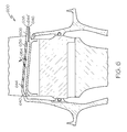
- FIG. 6 is a close-up view of a portion of a turbine rotor assembly 600 including a blade having a platform cooling circuit 640, according to another embodiment.
- outlets 644 are disposed at about a 45° angle 654 relative to a surface of an airfoil-facing wall 636.
- one or more of the outlets 644' can be formed through a trailing side edge 638 of a platform 606 so that the air in the platform cooling circuit 640 is expelled out an aft side 646 of the blade 600.
- a single outlet 644' is illustrated, more can be included.
- Each outlet 644' has a largest diameter in a range of about 0.3 to about 1 mm. In other embodiments, the outlets 644' can be larger or smaller than the aforementioned range.
- the outlets 644' are uniformly shaped, in an embodiment. In another embodiment, one or more of the outlets 644' have different shapes. For example, although depicted as generally cylindrically-shaped in FIG. 6 , the outlets 644' can have a circular, ovular, triangular or other shape cross section.
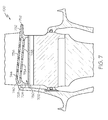
- FIG. 7 is a close-up view of a portion of a turbine rotor assembly 700 including a blade having a platform cooling circuit 740, according to still another embodiment.
- the blade 702, platform cooling circuit 740, outlets 744 and airfoil-facing wall 736 are formed substantially similar to blade 602, circuit 640, outlets 644 and airfoil-facing wall 636 of FIG. 6 , except that inlets 734 are formed through a root-facing wall 738 instead of the leading side edge wall.
- cooling air supply holes 724 (only one of which is shown) are formed through a leading side edge wall 728 of a platform 732 so that cooling air can be supplied through holes 724 to the outer radial cavity 750 to supply flow to inlets 734.
- each inlet 734 has a largest diameter in a range of about 0.3 to about 1 mm. In other embodiments, the inlets 734 can be larger or smaller than the aforementioned range.
- the inlets 734 are uniformly shaped, in an embodiment. In another embodiment, one or more of the inlets 734 have different shapes. For example, although depicted as generally cylindrically-shaped in FIG. 7 , the inlets 734 can have a circular, ovular, triangular or other shape cross section. Seven inlets 734 are illustrated in FIG. 7 , however it will be appreciated that more or fewer are included in other embodiments. For example, more than seven inlets 734 can be formed randomly over an entirety of the root-facing wall 738.
- the more than seven inlets 734 are aligned in two or more rows on the root-facing wall 738.
- the inlets 734 are disposed at an angle relative to a surface of the root-facing wall 738.
- the inlets 734 are substantially orthogonal to the surface of the root-facing wall 738.
- the angle at which the inlets 734 are disposed are in a range of about 45° to about 90°.
- the cooling air serves as impingement air to cool the blade platform 736.
- the air in the cooling cavity 740 then exits through an exit channel 752 or through platform cooling holes 744. Although a single exit channel 752 is illustrated, more or fewer may be included in other embodiments.
- FIGs. 5-7 are depicted as being formed on a pressure side of a blade, it will be appreciated that any of the configurations and/or concepts included in FIGs. 5-7 alternatively or additionally can be implemented for a suction side of the blade.
- FIG. 8 is a cross section view of two adjacent blades 800, 800', according to an embodiment.
- the blades 800, 800' each include an internal cooling circuit 802, 802', pressure side platform cooling circuits 804, 804', and suction side platform cooling circuits 806, 806'.
- the internal and pressure side platform cooling circuits 802, 802', 804, 804' are configured substantially similar to the internal cooling circuits 326, 426 (in FIGs. 3 and 4 ) and pressure side platform cooling circuits 340, 440, 540, 640, 740 (in FIGs. 3-7 ).
- the suction side platform cooling circuits 806, 806' are depicted in FIG. 8 as including an outlet 808, 808' through a suction side edge 810, 810' of a platform 812, 812'.
- outlets 808, 808' are illustrated in FIG. 8 for each blade 800, 800', more can be included.
- each outlet 808, 808' has a largest diameter in a range of about 0.3 to about 1 mm. In other embodiments, the outlets 808, 808' can be larger or smaller than the aforementioned range.
- the outlets 808, 808' are uniformly shaped, in an embodiment. In another embodiment, one or more of the outlets 808, 808' have different shapes. For example, although depicted as generally cylindrically-shaped in FIG. 8 , the outlets 808, 808' can have a circular, ovular, triangular or other shape cross section.
- FIG. 8 depicts the outlets 808, 808' of the suction side platform cooling circuits 806, 806' as being formed in the suction side edge 810, 810', it will be appreciated that outlets 814, 814' (depicted in phantom) of the pressure side platform cooling circuits 804, 804' can be formed through a pressure side edge 816, 816', in an embodiment.
- the outlets 808,808' and 814,814' may be utilized to cool the adjacent blade platform or may be directed out a platform aft side outlet (for example, an outlet similar to outlet 752 in FIG. 7 )
- cool air is directed from a cool air source, through a delivery channel, through supply holes and into the outer radial cavity.
- cool air is directly bled from the cool air source and into the platform cooling circuit to maximize platform cooling.
- cooling of the platform can be strategically accomplished.
Abstract
Description
- The inventive subject matter described herein generally relates to turbine rotor assemblies, and more particularly relates to turbine blades for use in turbine rotor assemblies.
- Gas turbine engines, such as turbofan gas turbine engines, may be used to power various types of vehicles and systems, such as, for example, aircraft. Typically, these engines include turbine blades that are impinged on by high-energy compressed air that causes a turbine of the engine to rotate at a high speed. Consequently, the blades are subjected to high heat and stress loadings which, over time, may reduce their structural integrity.
- To improve blade structural integrity, a blade cooling scheme is typically incorporated into the turbines. The blade cooling scheme directs cooling air through an internal cooling circuit formed in the blade to maintain blade temperatures within acceptable limits. The internal cooling circuit may include a simple channel extending through a length of the blade or may consist of a series of connected, serpentine cooling passages, which incorporate raised or depressed structures therein. The serpentine cooling passages increase the cooling effectiveness by extending the length of the air flow path. In this regard, the blade may have multiple internal walls that form the intricate cooling passages through which the cooling air flows. The cooling passages then direct the cooling air to openings on a tip and a trailing edge of the blade.
- As the desire for increased engine efficiency continues to rise, engine components are increasingly being subjected to higher and higher operating temperatures. For example, newer engine designs may employ operating temperatures that are about 150° C higher than conventional operating temperatures. However, current engine components, such as the blades, may not be as efficiently designed as desired. For example, certain portions of the blade, such as a platform of the blade, draw cooling air from the internal cooling circuit. However, bleeding cooling air from the internal cooling circuit can increase pressure loss. Additionally, in an event in which a structure of the internal cooling circuit is compromised, platform cooling may be adversely affected.
- Accordingly, it is desirable to have an improved system for cooling a blade. In addition, it is desirable to for the improved system to adequately cool the blade platform with minimal pressure loss. Furthermore, other desirable features and characteristics of the inventive subject matter will become apparent from the subsequent detailed description of the inventive subject matter and the appended claims, taken in conjunction with the accompanying drawings and this background of the inventive subject matter.
- In an embodiment, by way of example only, a turbine rotor assembly includes a rotor, a blade extending from the rotor, and a seal plate. The blade includes an airfoil defined by a convex suction side wall, a concave pressure side wall, a leading edge, a trailing edge, a root, and a tip, the walls and the tip each including an interior surface that defines an interior with the root, the interior including an airfoil cooling circuit for directing airflow through the blade, and a platform supporting the airfoil and having a leading side edge, a trailing side edge, suction side edge, a pressure side edge, an airfoil-facing wall, and a root-facing wall, the platform including a platform cooling circuit having an inlet on the leading side edge and an outlet. The seal plate is disposed adjacent to the rotor to form a cool air cavity for directing cool air to the cooling hole.
- In another embodiment, by way of example only, a turbine blade includes an airfoil defined by a convex suction side wall, a concave pressure side wall, a leading edge, a trailing edge, a root, and a tip, the walls and the tip each including an interior surface that defines an interior with the root, the interior including an airfoil cooling circuit for directing airflow through the blade, and a platform supporting the airfoil and having a leading side edge, a trailing side edge, suction side edge, a pressure side edge, an airfoil-facing wall, and a root-facing wall, the platform including a platform cooling circuit having an inlet on the leading side edge and an outlet.
- In still another embodiment, by way of example only, a turbine rotor assembly includes a rotor, a blade extending from the rotor, and a seal plate. The blade includes an airfoil defined by a convex suction side wall, a concave pressure side wall, a leading edge, a trailing edge, a root, and a tip, the walls and the tip each including an interior surface that defines an interior with the root, the interior including an airfoil cooling circuit for directing airflow through the blade, and a platform supporting the airfoil and having a leading side edge, a trailing side edge, suction side edge, a pressure side edge, an airfoil-facing wall, and a root-facing wall, the platform including a platform cooling circuit having a cooling air supply hole on the leading side edge of the platform, an inlet on the root-facing wall, and an outlet. The seal plate is disposed adjacent to the rotor to form a cool air cavity for directing cool air to the cooling hole.
- The inventive subject matter will hereinafter be described in conjunction with the following drawing figures, wherein like numerals denote like elements, and
-
FIG. 1 is a partial cross-sectional side view of a high pressure turbine stage of an engine, according to an embodiment; -
FIG. 2 close-up view of a portion of a turbine rotor assembly including a blade having a cooling system, according to an embodiment; -
FIG. 3 is a reverse image of a top view of a blade including a platform cooling circuit; according to an embodiment; -
FIG. 4 is a reverse image of a top view of a blade including a platform cooling circuit; according to another embodiment; -
FIG. 5 is a close-up view of a portion of a turbine rotor assembly including a platform cooling circuit, according to an embodiment; -
FIG. 6 is a close-up view of a portion of a turbine rotor assembly including a platform cooling circuit, according to another embodiment; -
FIG. 7 is a close-up view of a portion of a turbine rotor assembly including a platform cooling circuit, according to still another embodiment; and -
FIG. 8 is a cross section view of two adjacent blades, according to an embodiment. - The following detailed description is merely exemplary in nature and is not intended to limit the inventive subject matter or the application and uses of the inventive subject matter. Furthermore, there is no intention to be bound by any theory presented in the preceding background or the following detailed description.
- A blade is provided that has improved platform cooling with minimal pressure loss. In an embodiment, the blade includes an airfoil defined by a convex suction side wall, a concave pressure side wall, a leading edge, a trailing edge, a root, and a tip, the walls and the tip each including an interior surface that defines an interior with the root, the interior including an airfoil cooling circuit for directing airflow through the blade, and a platform supporting the airfoil and having a leading side edge, a trailing side edge, suction side edge, a pressure side edge, an airfoil-facing wall, and a root-facing wall, the platform including a platform cooling circuit having an inlet on the leading side edge and an outlet. The outlet can be formed on one or more of the airfoil-facing wall, the pressure side edge, the suction side edge, and/or the trailing side edge.
-
FIG. 1 is a partial cross-sectional side view of a highpressure turbine stage 102 of anengine 100, according to an embodiment. The highpressure turbine stage 102 includes aturbine stator 104 and aturbine rotor assembly 106, both surrounded by ashroud 108 defining a gas flow path through which hot, combusted air from an upstream compressor section (not shown) is directed. Theturbine stator 104 directs the air toward theturbine rotor assembly 106. The air impinges uponblades 110 of theturbine rotor assembly 106, causing theturbine rotor assembly 106 to rotate. - To allow the high
pressure turbine stage 102 to operate as intended, certain components of thestage 102 are cooled. For example, theblades 110 of theturbine rotor assembly 106 include an internal cooling system.FIG. 2 is a close-up view of a portion of aturbine rotor assembly 200 including ablade 202 having a cooling system, according to an embodiment. Theturbine rotor assembly 200 includes aforward seal plate 204, aturbine disk 206, blades 202 (only one of which is shown), and anaft seal plate 205, in an embodiment. Theforward seal plate 204 is spaced apart from theturbine disk 206 to form aflow cavity 208. Theflow cavity 208 is configured to be in flow communication with a cool air source (e.g., a compressor section, not shown). Anannular sealing flange 214 divides theflow cavity 208 into an innerradial cavity 210 and an outerradial cavity 212. - The
annular sealing flange 214 extends axially from theforward seal plate 204 and is configured to seal against aroot 216 of acorresponding blade 202 in theturbine disk 206. In this regard, theannular sealing flange 214 is disposed radially inward from anouter diameter 217 of theforward seal plate 204. In an embodiment, theannular sealing flange 214 has a relativelyflat sealing surface 220 for contacting theblade 202. The sealingflange 214 can include a sealingring 218 formed in a suitably located groove 222 in theannular sealing flange 214 to improve sealing. The cool air from theflow cavity 208 is directed to theblade 202 to cool theblade 202. - The
blade 202 includes anairfoil 230, aplatform 232, and theroot 216. Theairfoil 230 is disposed over theplatform 232, which includes aplatform cooling circuit 234 formed therein. Generally, theplatform cooling circuit 234 has aninlet 236 for receiving the cool air and channels 238 (one of which is depicted) for flowing the cool air through theplatform 232. In an embodiment, theinlet 236 is formed on a leading side edge wall of theplatform 228. To provide the outerradial cavity 212 with the cool air, adelivery channel 240 is formed through theforward seal plate 204. In an embodiment, thedelivery channel 240 extends behind the groove 222 of theforward seal plate 204. Alternatively, as shown in phantom inFIG. 2 , the delivery channel 240' is formed through theroot 216, which is disposed in ablade slot 248 of theturbine disk 206. Because an innerradial surface 242 of theroot 216 is spaced apart from the surface defining theblade slot 248 to form aflow channel 244, the delivery channel 240' can extend from theflow channel 244 to a leadingside wall 246 of theroot 216 and to flow cool air from theflow channel 244 into the outerradial cavity 212. Although asingle delivery channel 240 is included inFIG. 2 , a plurality ofdelivery channels 240 can be included at various locations around theannular sealing flange 214, in other embodiments. In such embodiments, thedelivery channels 240 may be substantially evenly spaced around theannular sealing flange 214 or unevenly spaced. -
FIG. 3 is a reverse image of a top view of ablade 300 including aplatform cooling circuit 302 and aninternal cooling circuit 326, according to an embodiment. Theblade 300 includes anairfoil 304 and aplatform 306. Theairfoil 304 is generally made up of a concave,pressure side wall 310, a convex,suction side wall 312 opposite the concave,pressure side wall 310, and atip wall 314 extending between and coupling thepressure sidewall 310 and thesuction side wall 312 together. Thewalls walls walls walls walls airfoil 304 is made up of aleading edge 316, a trailingedge 318, apressure side 320 along the concave,pressure side wall 310, asuction side 322 along the convex,suction side wall 312. Thewalls internal cooling circuit 326, which receives cool air through aroot 308 and discharges the cool air out slots or openings (not shown) in theblade 300. - The
platform 306 supports theairfoil 304 and has a leadingside edge 328, a trailingside edge 330, apressure side edge 332, asuction side edge 334, an airfoil-facing wall 736 (shown inFigure 7 ), and a root-facing wall 738 (shown inFigure 7 ). A length measured from the leadingside edge 328 to the trailingside edge 330 is greater than a length measured from theairfoil leading edge 316 to theairfoil trailing edge 318. In an embodiment, the length between the leading and trailing side edges 328, 330 is in a range of about 2 cm to about 5 cm, and the length between the airfoil leading and trailing side edges 316, 318 is in a range of about 1.9 cm to about 4.9 cm. In another embodiment, the lengths are greater or less than the aforementioned ranges. A width measured between the pressure and suction side edges 332, 334 is greater than a largest width measured between the pressure andsuction side walls suction side walls - The
platform 306 includes aplatform cooling circuit 340 configured to provide cool air to theplatform 306. Theplatform cooling circuit 340 can include one or both of a pressure side platform cooling circuit 341 and/or a suction side cooling circuit 343 (shown in phantom). The pressure side platform cooling circuit 341 has a plurality ofinlets 342 andoutlets 344. Theinlets 342 are formed on the leadingside edge 328 of theplatform 306 to be in communication with the outer radial cavity 212 (FIG. 2 ) to thereby receive cool air therefrom. Although threeinlets 342 are illustrated, fewer or more can be included in other embodiments. Eachinlet 342 has a circular flow area, in an embodiment. Alternatively, one ormore inlet 342 has a different shape flow area. In another embodiment, all of theinlets 342 are substantially identically shaped. However, it will be appreciated that one or more of theinlets 342 can have a flow area that has a different shape than the others. In an embodiment, eachinlet 342 has a largest diameter in a range of about 0.3 to about 1 mm. It will be appreciated, however that theinlets 342 can have larger or smaller largest diameters in other embodiments. - The pressure side platform cooling circuit 341 is independent from the
internal cooling circuit 326 of theblade 300. The pressure side platform cooling circuit 341 generally comprises achannel 348 that extends from correspondinginlets 342 to correspondingoutlets 344. Thechannel 348 comprises a serpentine channel, as depicted inFIG. 3 . In still another embodiment, one or more of thechannels 348 may or may not be connected and may have a curved shape or another shape. - As noted briefly above, the platform cooling circuit (e.g., circuit 340) can also or alternatively include the suction side cooling circuit (e.g., circuits 343, 443). The suction side cooling circuit 343 is configured to provide cool air to a
platform 306 and has a plurality ofinlets 352 andoutlets 354. Theinlets 352 are formed on a leadingside edge 328 of theplatform 306 to be in communication with the outer radial cavity 212 (FIG. 2 ) to thereby receive cool air therefrom. Although threeinlets 352 are illustrated, fewer or more can be included in other embodiments. Eachinlet 352 has a circular flow area, in an embodiment. Alternatively, one ormore inlet 352 has a different shape flow area. In another embodiment, all of theinlets 352 are substantially identically shaped. However, it will be appreciated that one or more of theinlets 352 can have a flow area that has a different shape than the others. In an embodiment, eachinlet 352 has a largest diameter in a range of about 0.3 to about 1 mm. It will be appreciated, however that theinlets 352 can have larger or smaller largest diameters in other embodiments. - The suction side cooling circuit 343 is independent from the
internal cooling circuit 326 of theblade 300. The suction side cooling circuit 343 generally comprises achannel 358 that extends from correspondinginlets 352 to correspondingoutlets 354. Thechannel 358 comprises a serpentine channel, as depicted inFIG. 3 . In still another embodiment, one or more of thechannels 358 may or may not be connected and may have a curved shape or another shape. -
FIG. 4 is a reverse image of a top view of ablade 400 including a platform cooling circuit 440 and aninternal cooling circuit 426, according to another embodiment. The platform cooling circuit 440 can include one or both of a pressure and/or suction sideplatform cooling circuits 441, 443, although the suction side circuit 443 is depicted in phantom. Theblade 400 includes anairfoil 404 and aplatform 406, and theinternal cooling circuit 426,airfoil 404, and platform are formed substantially similar to theinternal cooling circuit 326,airfoil 304, andplatform 306 ofFIG. 3 . Theplatform cooling circuits 441, 443 are formed as two or more channels that extend from a leadingside edge 428 toward the trailingside edge 430 and includes a plurality ofpin fins 432 extending through the channels. Thepin fins 432 are included to serve as heat transfer elements to thereby improve cooling. Although thepin fins 432 are aligned in three rows, they can alternatively be disposed in a random pattern. In other embodiments, thepin fins 432 are not cylindrical and have a different shape. Moreover, although eighteentotal pin fins 432 are included, more or fewer can be included for other embodiments. - As noted above, the
platform cooling circuits 340, 440 includesoutlets 344.FIG. 5 is a close-up view of a portion of aturbine rotor assembly 500 including a blade having aplatform cooling circuit 540, according to an embodiment. Theoutlets 544 extend through an airfoil-facingwall 536 to providing a cooling film for thewall 536. In an embodiment, eachoutlet 544 has a largest diameter in a range of about 0.3 to about 1 mm. In other embodiments, theoutlets 544 can be larger or smaller than the aforementioned range. Theoutlets 544 are uniformly shaped, in an embodiment. In another embodiment, one or more of theoutlets 544 have different shapes. For example, although depicted as generally cylindrically-shaped inFIG. 5 , theoutlets 544 can have a circular, ovular, triangular or other shape cross section. Sevenoutlets 544 are illustrated inFIG. 5 , however it will be appreciated that more or fewer are included in other embodiments. For example, more than sevenoutlets 544 can be formed randomly over an entirety of the airfoil-facingwall 536. In other embodiments, the more than sevenoutlets 544 are aligned in two or more rows on the airfoil-facingwall 536. Theoutlets 544 are disposed at anangle 554 relative to a surface of the airfoil-facingwall 536. In an embodiment, theangle 554 at which theoutlets 544 are disposed are in a range of about 25° to about 90°. As depicted inFIG. 5 , theoutlets 544 are substantially orthogonal to the surface of the airfoil-facingwall 536. - In other embodiments, the
outlets 544 are disposed at a different angle.FIG. 6 is a close-up view of a portion of aturbine rotor assembly 600 including a blade having aplatform cooling circuit 640, according to another embodiment. Here,outlets 644 are disposed at about a 45°angle 654 relative to a surface of an airfoil-facingwall 636. - In addition, or alternatively, to being disposed on the airfoil-facing
wall 636, one or more of the outlets 644' can be formed through a trailingside edge 638 of a platform 606 so that the air in theplatform cooling circuit 640 is expelled out anaft side 646 of theblade 600. Although a single outlet 644' is illustrated, more can be included. For example, between 1 to 10 outlets 644' can be formed on the trailingside edge 638. Each outlet 644' has a largest diameter in a range of about 0.3 to about 1 mm. In other embodiments, the outlets 644' can be larger or smaller than the aforementioned range. The outlets 644' are uniformly shaped, in an embodiment. In another embodiment, one or more of the outlets 644' have different shapes. For example, although depicted as generally cylindrically-shaped inFIG. 6 , the outlets 644' can have a circular, ovular, triangular or other shape cross section. -
FIG. 7 is a close-up view of a portion of aturbine rotor assembly 700 including a blade having aplatform cooling circuit 740, according to still another embodiment. Here, theblade 702,platform cooling circuit 740,outlets 744 and airfoil-facingwall 736 are formed substantially similar to blade 602,circuit 640,outlets 644 and airfoil-facingwall 636 ofFIG. 6 , except thatinlets 734 are formed through a root-facingwall 738 instead of the leading side edge wall. Additionally, cooling air supply holes 724 (only one of which is shown) are formed through a leadingside edge wall 728 of aplatform 732 so that cooling air can be supplied throughholes 724 to the outerradial cavity 750 to supply flow toinlets 734. In an embodiment, eachinlet 734 has a largest diameter in a range of about 0.3 to about 1 mm. In other embodiments, theinlets 734 can be larger or smaller than the aforementioned range. Theinlets 734 are uniformly shaped, in an embodiment. In another embodiment, one or more of theinlets 734 have different shapes. For example, although depicted as generally cylindrically-shaped inFIG. 7 , theinlets 734 can have a circular, ovular, triangular or other shape cross section. Seveninlets 734 are illustrated inFIG. 7 , however it will be appreciated that more or fewer are included in other embodiments. For example, more than seveninlets 734 can be formed randomly over an entirety of the root-facingwall 738. In other embodiments, the more than seveninlets 734 are aligned in two or more rows on the root-facingwall 738. Theinlets 734 are disposed at an angle relative to a surface of the root-facingwall 738. Theinlets 734 are substantially orthogonal to the surface of the root-facingwall 738. In other embodiments, as depicted inFIG. 7 , the angle at which theinlets 734 are disposed are in a range of about 45° to about 90°. - In embodiments in which the cooling air enters through the root-facing
wall 738, the cooling air serves as impingement air to cool theblade platform 736. The air in thecooling cavity 740 then exits through anexit channel 752 or through platform cooling holes 744. Although asingle exit channel 752 is illustrated, more or fewer may be included in other embodiments. - Although
FIGs. 5-7 are depicted as being formed on a pressure side of a blade, it will be appreciated that any of the configurations and/or concepts included inFIGs. 5-7 alternatively or additionally can be implemented for a suction side of the blade. -
FIG. 8 is a cross section view of twoadjacent blades 800, 800', according to an embodiment. Theblades 800, 800' each include aninternal cooling circuit 802, 802', pressure sideplatform cooling circuits 804, 804', and suction sideplatform cooling circuits 806, 806'. The internal and pressure sideplatform cooling circuits internal cooling circuits 326, 426 (inFIGs. 3 and 4 ) and pressure sideplatform cooling circuits FIGs. 3-7 ). The suction sideplatform cooling circuits 806, 806' are depicted inFIG. 8 as including anoutlet 808, 808' through asuction side edge 810, 810' of aplatform 812, 812'. - Although a
single outlet 808, 808' is illustrated inFIG. 8 for eachblade 800, 800', more can be included. For example, between 1 to 10outlets 808, 808' can be formed on thesuction side edge 810, 810'. Eachoutlet 808, 808' has a largest diameter in a range of about 0.3 to about 1 mm. In other embodiments, theoutlets 808, 808' can be larger or smaller than the aforementioned range. Theoutlets 808, 808' are uniformly shaped, in an embodiment. In another embodiment, one or more of theoutlets 808, 808' have different shapes. For example, although depicted as generally cylindrically-shaped inFIG. 8 , theoutlets 808, 808' can have a circular, ovular, triangular or other shape cross section. - Although
FIG. 8 depicts theoutlets 808, 808' of the suction sideplatform cooling circuits 806, 806' as being formed in thesuction side edge 810, 810', it will be appreciated thatoutlets 814, 814' (depicted in phantom) of the pressure sideplatform cooling circuits 804, 804' can be formed through apressure side edge 816, 816', in an embodiment. The outlets 808,808' and 814,814' may be utilized to cool the adjacent blade platform or may be directed out a platform aft side outlet (for example, an outlet similar tooutlet 752 inFIG. 7 ) - In any case, during operation, cool air is directed from a cool air source, through a delivery channel, through supply holes and into the outer radial cavity. By including supply holes on the leading side edge and by forming the platform cooling circuit independent from the blade internal cooling circuit, cool air is directly bled from the cool air source and into the platform cooling circuit to maximize platform cooling. Additionally, by tailoring the location of the outlets on the airfoil-facing wall and/or the trailing side edge, cooling of the platform can be strategically accomplished.
- While at least one exemplary embodiment has been presented in the foregoing detailed description of the inventive subject matter, it should be appreciated that a vast number of variations exist. It should also be appreciated that the exemplary embodiment or exemplary embodiments are only examples, and are not intended to limit the scope, applicability, or configuration of the inventive subject matter in any way. Rather, the foregoing detailed description will provide those skilled in the art with a convenient road map for implementing an exemplary embodiment of the inventive subject matter. It being understood that various changes may be made in the function and arrangement of elements described in an exemplary embodiment without departing from the scope of the inventive subject matter as set forth in the appended claims.
Claims (10)
- A turbine rotor assembly, comprising:a rotor;a blade extending from the rotor, the blade including:an airfoil defined by a convex suction side wall, a concave pressure side wall, a leading edge, a trailing edge, a root, and a tip, the walls and the tip each including an interior surface that defines an interior with the root, the interior including an airfoil cooling circuit for directing airflow through the blade, anda platform supporting the airfoil and having a leading side edge, a trailing side edge, suction side edge, a pressure side edge, an airfoil-facing wall, and a root-facing wall, the platform including a platform cooling circuit having an inlet on the leading side edge and an outlet, anda seal plate disposed adjacent to the rotor to form a cool air cavity for directing cool air to the cooling hole.
- The turbine rotor assembly of claim 1, wherein the platform cooling circuit comprises a serpentine channel or a channel including pin fins extending therethrough.
- The turbine rotor assembly of claim 1, wherein the outlet of the platform cooling circuit extends through the airfoil-facing wall of the platform and is disposed at an angle in a range of about 25° and about 90° relative to a surface of the airfoil-facing wall of the platform.
- The turbine rotor assembly of claim 1, wherein the outlet extends through either the suction side edge of the platform or the pressure side edge of the platform.
- The turbine rotor assembly of claim 1, wherein:the inlet extends through the root-facing wall of the platform.; andthe turbine rotor assembly further comprises an aft seal plate having a forward side and an aft side, the forward face disposed against the root of the airfoil.
- The turbine rotor assembly of claim 1, wherein the outlet of the blade platform circuit comprises a plurality of holes formed on the trailing side edge of the platform.
- The turbine rotor assembly of claim 1, wherein the platform cooling circuit is independent from the airfoil cooling circuit.
- The turbine rotor assembly of claim 1, wherein:the rotor including a blade slot;the seal plate includes a sealing flange extending axially from the seal plate to contact the blade;the root is disposed in the blade slot and forming a flow channel with a surface defining the blade slot, the root including a delivery channel extending from the flow channel to a leading side wall of the root, the delivery channel configured to flow cool air from the flow channel into a cavity formed between the seal plate and the leading side wall of the blade and into the inlet of the platform cooling circuit.
- The turbine rotor assembly of claim 1, wherein:the seal plate includes a sealing flange extending axially from the seal plate to contact the blade, and a cooling channel is formed through the sealing flange configured to flow cool air into a cavity formed between the seal plate and the leading side edge of the blade and into the inlet of the platform cooling circuit.
- A turbine blade comprising:an airfoil defined by a convex suction side wall, a concave pressure side wall, a leading edge, a trailing edge, a root, and a tip, the walls and the tip each including an interior surface that defines an interior with the root, the interior including an airfoil cooling circuit for directing airflow through the blade; anda platform supporting the airfoil and having a leading side edge, a trailing side edge, suction side edge, a pressure side edge, an airfoil-facing wall, and a root-facing wall, the platform including a platform cooling circuit having an inlet on the leading side edge and an outlet.
Applications Claiming Priority (1)
| Application Number | Priority Date | Filing Date | Title |
|---|---|---|---|
| US12/903,763 US8636470B2 (en) | 2010-10-13 | 2010-10-13 | Turbine blades and turbine rotor assemblies |
Publications (3)
| Publication Number | Publication Date |
|---|---|
| EP2441920A2 true EP2441920A2 (en) | 2012-04-18 |
| EP2441920A3 EP2441920A3 (en) | 2014-10-08 |
| EP2441920B1 EP2441920B1 (en) | 2015-08-12 |
Family
ID=44720802
Family Applications (1)
| Application Number | Title | Priority Date | Filing Date |
|---|---|---|---|
| EP11184232.4A Active EP2441920B1 (en) | 2010-10-13 | 2011-10-06 | Turbine rotor assembly |
Country Status (2)
| Country | Link |
|---|---|
| US (1) | US8636470B2 (en) |
| EP (1) | EP2441920B1 (en) |
Cited By (8)
| Publication number | Priority date | Publication date | Assignee | Title |
|---|---|---|---|---|
| WO2015026598A1 (en) | 2013-08-20 | 2015-02-26 | United Technologies Corporation | Gas turbine engine component providing prioritized cooling |
| FR3026430A1 (en) * | 2014-09-29 | 2016-04-01 | Snecma | TURBINE WHEEL IN A TURBOMACHINE |
| EP3084137A4 (en) * | 2013-12-19 | 2017-01-25 | United Technologies Corporation | Turbine airfoil cooling |
| EP3102793A4 (en) * | 2014-01-24 | 2017-12-06 | United Technologies Corporation | Toggle seal for a rim seal |
| US10612406B2 (en) | 2018-04-19 | 2020-04-07 | United Technologies Corporation | Seal assembly with shield for gas turbine engines |
| US11220924B2 (en) | 2019-09-26 | 2022-01-11 | Raytheon Technologies Corporation | Double box composite seal assembly with insert for gas turbine engine |
| US11352897B2 (en) | 2019-09-26 | 2022-06-07 | Raytheon Technologies Corporation | Double box composite seal assembly for gas turbine engine |
| US11359507B2 (en) | 2019-09-26 | 2022-06-14 | Raytheon Technologies Corporation | Double box composite seal assembly with fiber density arrangement for gas turbine engine |
Families Citing this family (12)
| Publication number | Priority date | Publication date | Assignee | Title |
|---|---|---|---|---|
| US10227875B2 (en) | 2013-02-15 | 2019-03-12 | United Technologies Corporation | Gas turbine engine component with combined mate face and platform cooling |
| FR3011031B1 (en) * | 2013-09-25 | 2017-12-29 | Herakles | ROTARY ASSEMBLY FOR TURBOMACHINE |
| EP3084136B8 (en) * | 2013-12-17 | 2021-04-07 | Raytheon Technologies Corporation | Rotor blade and corresponding method of cooling a platform of a rotor blade |
| US10465523B2 (en) * | 2014-10-17 | 2019-11-05 | United Technologies Corporation | Gas turbine component with platform cooling |
| US10066485B2 (en) * | 2015-12-04 | 2018-09-04 | General Electric Company | Turbomachine blade cover plate having radial cooling groove |
| US10082033B2 (en) * | 2016-01-12 | 2018-09-25 | United Technologies Corporation | Gas turbine blade with platform cooling |
| US20190264569A1 (en) * | 2018-02-23 | 2019-08-29 | General Electric Company | Turbine rotor blade with exiting hole to deliver fluid to boundary layer film |
| DE102018207873A1 (en) | 2018-05-18 | 2019-11-21 | MTU Aero Engines AG | Blade for a turbomachine |
| FR3101670B1 (en) * | 2019-10-08 | 2021-10-08 | Safran Aircraft Engines | Injector for a high pressure turbine |
| US11401814B2 (en) | 2020-01-17 | 2022-08-02 | Raytheon Technologies Corporation | Rotor assembly with internal vanes |
| US11286781B2 (en) * | 2020-01-17 | 2022-03-29 | Raytheon Technologies Corporation | Multi-disk bladed rotor assembly for rotational equipment |
| US11401819B2 (en) * | 2020-12-17 | 2022-08-02 | Solar Turbines Incorporated | Turbine blade platform cooling holes |
Family Cites Families (24)
| Publication number | Priority date | Publication date | Assignee | Title |
|---|---|---|---|---|
| BE543383A (en) * | 1954-12-06 | |||
| US3017159A (en) * | 1956-11-23 | 1962-01-16 | Curtiss Wright Corp | Hollow blade construction |
| US3834831A (en) * | 1973-01-23 | 1974-09-10 | Westinghouse Electric Corp | Blade shank cooling arrangement |
| US5135354A (en) * | 1990-09-14 | 1992-08-04 | United Technologies Corporation | Gas turbine blade and disk |
| JPH0571305A (en) * | 1991-03-04 | 1993-03-23 | General Electric Co <Ge> | Platform assembly installing rotor blade to rotor disk |
| CA2198225C (en) | 1994-08-24 | 2005-11-22 | Leroy D. Mclaurin | Gas turbine blade with cooled platform |
| EP0789806B1 (en) * | 1994-10-31 | 1998-07-29 | Westinghouse Electric Corporation | Gas turbine blade with a cooled platform |
| FR2758855B1 (en) * | 1997-01-30 | 1999-02-26 | Snecma | VENTILATION SYSTEM FOR MOBILE VANE PLATFORMS |
| US5848876A (en) | 1997-02-11 | 1998-12-15 | Mitsubishi Heavy Industries, Ltd. | Cooling system for cooling platform of gas turbine moving blade |
| JP3758792B2 (en) | 1997-02-25 | 2006-03-22 | 三菱重工業株式会社 | Gas turbine rotor platform cooling mechanism |
| CA2262064C (en) | 1998-02-23 | 2002-09-03 | Mitsubishi Heavy Industries, Ltd. | Gas turbine moving blade platform |
| US6190130B1 (en) * | 1998-03-03 | 2001-02-20 | Mitsubishi Heavy Industries, Ltd. | Gas turbine moving blade platform |
| CA2231988C (en) | 1998-03-12 | 2002-05-28 | Mitsubishi Heavy Industries, Ltd. | Gas turbine blade |
| DE60045026D1 (en) * | 1999-09-24 | 2010-11-11 | Gen Electric | Gas turbine blade with impact cooled platform |
| DE10064265A1 (en) | 2000-12-22 | 2002-07-04 | Alstom Switzerland Ltd | Device and method for cooling a platform of a turbine blade |
| US6945749B2 (en) * | 2003-09-12 | 2005-09-20 | Siemens Westinghouse Power Corporation | Turbine blade platform cooling system |
| US7600972B2 (en) | 2003-10-31 | 2009-10-13 | General Electric Company | Methods and apparatus for cooling gas turbine engine rotor assemblies |
| US7097424B2 (en) | 2004-02-03 | 2006-08-29 | United Technologies Corporation | Micro-circuit platform |
| US7144215B2 (en) | 2004-07-30 | 2006-12-05 | General Electric Company | Method and apparatus for cooling gas turbine engine rotor blades |
| US7467922B2 (en) * | 2005-07-25 | 2008-12-23 | Siemens Aktiengesellschaft | Cooled turbine blade or vane for a gas turbine, and use of a turbine blade or vane of this type |
| US7416391B2 (en) * | 2006-02-24 | 2008-08-26 | General Electric Company | Bucket platform cooling circuit and method |
| US7695247B1 (en) | 2006-09-01 | 2010-04-13 | Florida Turbine Technologies, Inc. | Turbine blade platform with near-wall cooling |
| ATE459447T1 (en) | 2006-10-16 | 2010-03-15 | Siemens Ag | TURBINE BLADE FOR A TURBINE WITH A COOLANT CHANNEL |
| US7610946B2 (en) | 2007-01-05 | 2009-11-03 | Honeywell International Inc. | Cooled turbine blade cast tip recess |
-
2010
- 2010-10-13 US US12/903,763 patent/US8636470B2/en active Active
-
2011
- 2011-10-06 EP EP11184232.4A patent/EP2441920B1/en active Active
Non-Patent Citations (1)
| Title |
|---|
| None |
Cited By (14)
| Publication number | Priority date | Publication date | Assignee | Title |
|---|---|---|---|---|
| US10215051B2 (en) | 2013-08-20 | 2019-02-26 | United Technologies Corporation | Gas turbine engine component providing prioritized cooling |
| WO2015026598A1 (en) | 2013-08-20 | 2015-02-26 | United Technologies Corporation | Gas turbine engine component providing prioritized cooling |
| EP3036405A1 (en) * | 2013-08-20 | 2016-06-29 | United Technologies Corporation | Gas turbine engine component providing prioritized cooling |
| EP3036405A4 (en) * | 2013-08-20 | 2017-05-10 | United Technologies Corporation | Gas turbine engine component providing prioritized cooling |
| EP3084137A4 (en) * | 2013-12-19 | 2017-01-25 | United Technologies Corporation | Turbine airfoil cooling |
| US10774666B2 (en) | 2014-01-24 | 2020-09-15 | Raytheon Technologies Corporation | Toggle seal for a rim seal |
| EP3102793A4 (en) * | 2014-01-24 | 2017-12-06 | United Technologies Corporation | Toggle seal for a rim seal |
| US9890652B2 (en) | 2014-09-29 | 2018-02-13 | Snecma | Turbine wheel for a turbine engine |
| FR3026430A1 (en) * | 2014-09-29 | 2016-04-01 | Snecma | TURBINE WHEEL IN A TURBOMACHINE |
| US10612406B2 (en) | 2018-04-19 | 2020-04-07 | United Technologies Corporation | Seal assembly with shield for gas turbine engines |
| US11220924B2 (en) | 2019-09-26 | 2022-01-11 | Raytheon Technologies Corporation | Double box composite seal assembly with insert for gas turbine engine |
| US11352897B2 (en) | 2019-09-26 | 2022-06-07 | Raytheon Technologies Corporation | Double box composite seal assembly for gas turbine engine |
| US11359507B2 (en) | 2019-09-26 | 2022-06-14 | Raytheon Technologies Corporation | Double box composite seal assembly with fiber density arrangement for gas turbine engine |
| US11732597B2 (en) | 2019-09-26 | 2023-08-22 | Raytheon Technologies Corporation | Double box composite seal assembly with insert for gas turbine engine |
Also Published As
| Publication number | Publication date |
|---|---|
| US8636470B2 (en) | 2014-01-28 |
| US20120093649A1 (en) | 2012-04-19 |
| EP2441920B1 (en) | 2015-08-12 |
| EP2441920A3 (en) | 2014-10-08 |
Similar Documents
| Publication | Publication Date | Title |
|---|---|---|
| US8636470B2 (en) | Turbine blades and turbine rotor assemblies | |
| US8777567B2 (en) | Turbine blades, turbine assemblies, and methods of manufacturing turbine blades | |
| US9546554B2 (en) | Gas turbine engine components with blade tip cooling | |
| US9920635B2 (en) | Turbine blades and methods of forming turbine blades having lifted rib turbulator structures | |
| US9394798B2 (en) | Gas turbine engines with turbine airfoil cooling | |
| EP2716866B1 (en) | Gas turbine engine components with lateral and forward sweep film cooling holes | |
| CA2870740C (en) | Turbine airfoil with local wall thickness control | |
| CN108868898B (en) | Apparatus and method for cooling an airfoil tip of a turbine engine | |
| US8677763B2 (en) | Method and apparatus for gas turbine engine temperature management | |
| EP2662528B1 (en) | Gas turbine engine component with cooling holes having a multi-lobe configuration | |
| EP2463479A2 (en) | Turbine rotor disks and turbine assemblies | |
| US10830057B2 (en) | Airfoil with tip rail cooling | |
| EP2639405B1 (en) | Turbine blade tip cooling | |
| US20200378262A1 (en) | Gas turbine engines with improved airfoil dust removal | |
| CA2957703A1 (en) | Gas turbine engine trailing edge ejection holes | |
| EP3048263A1 (en) | Active clearance control systems | |
| US9562437B2 (en) | Turbine blade airfoils including film cooling systems, and methods for forming an improved film cooled airfoil of a turbine blade | |
| CN108691571B (en) | Engine component with flow enhancer | |
| US20190153872A1 (en) | Turbine engine with component having a cooled tip |
Legal Events
| Date | Code | Title | Description |
|---|---|---|---|
| PUAI | Public reference made under article 153(3) epc to a published international application that has entered the european phase |
Free format text: ORIGINAL CODE: 0009012 |
|
| 17P | Request for examination filed |
Effective date: 20111006 |
|
| AK | Designated contracting states |
Kind code of ref document: A2 Designated state(s): AL AT BE BG CH CY CZ DE DK EE ES FI FR GB GR HR HU IE IS IT LI LT LU LV MC MK MT NL NO PL PT RO RS SE SI SK SM TR |
|
| AX | Request for extension of the european patent |
Extension state: BA ME |
|
| PUAL | Search report despatched |
Free format text: ORIGINAL CODE: 0009013 |
|
| AK | Designated contracting states |
Kind code of ref document: A3 Designated state(s): AL AT BE BG CH CY CZ DE DK EE ES FI FR GB GR HR HU IE IS IT LI LT LU LV MC MK MT NL NO PL PT RO RS SE SI SK SM TR |
|
| AX | Request for extension of the european patent |
Extension state: BA ME |
|
| RIC1 | Information provided on ipc code assigned before grant |
Ipc: F01D 5/30 20060101ALI20140904BHEP Ipc: F01D 5/08 20060101AFI20140904BHEP |
|
| 17Q | First examination report despatched |
Effective date: 20140923 |
|
| REG | Reference to a national code |
Ref country code: DE Ref legal event code: R079 Ref document number: 602011018624 Country of ref document: DE Free format text: PREVIOUS MAIN CLASS: F01D0005180000 Ipc: F01D0005080000 |
|
| GRAP | Despatch of communication of intention to grant a patent |
Free format text: ORIGINAL CODE: EPIDOSNIGR1 |
|
| RIC1 | Information provided on ipc code assigned before grant |
Ipc: F01D 5/08 20060101AFI20150218BHEP Ipc: F01D 5/30 20060101ALI20150218BHEP |
|
| INTG | Intention to grant announced |
Effective date: 20150323 |
|
| GRAS | Grant fee paid |
Free format text: ORIGINAL CODE: EPIDOSNIGR3 |
|
| GRAA | (expected) grant |
Free format text: ORIGINAL CODE: 0009210 |
|
| AK | Designated contracting states |
Kind code of ref document: B1 Designated state(s): AL AT BE BG CH CY CZ DE DK EE ES FI FR GB GR HR HU IE IS IT LI LT LU LV MC MK MT NL NO PL PT RO RS SE SI SK SM TR |
|
| REG | Reference to a national code |
Ref country code: GB Ref legal event code: FG4D |
|
| REG | Reference to a national code |
Ref country code: CH Ref legal event code: EP |
|
| REG | Reference to a national code |
Ref country code: AT Ref legal event code: REF Ref document number: 742348 Country of ref document: AT Kind code of ref document: T Effective date: 20150815 |
|
| REG | Reference to a national code |
Ref country code: IE Ref legal event code: FG4D |
|
| REG | Reference to a national code |
Ref country code: DE Ref legal event code: R096 Ref document number: 602011018624 Country of ref document: DE |
|
| RAP2 | Party data changed (patent owner data changed or rights of a patent transferred) |
Owner name: HONEYWELL INTERNATIONAL INC. |
|
| REG | Reference to a national code |
Ref country code: LT Ref legal event code: MG4D |
|
| REG | Reference to a national code |
Ref country code: AT Ref legal event code: MK05 Ref document number: 742348 Country of ref document: AT Kind code of ref document: T Effective date: 20150812 |
|
| REG | Reference to a national code |
Ref country code: NL Ref legal event code: MP Effective date: 20150812 |
|
| PG25 | Lapsed in a contracting state [announced via postgrant information from national office to epo] |
Ref country code: FI Free format text: LAPSE BECAUSE OF FAILURE TO SUBMIT A TRANSLATION OF THE DESCRIPTION OR TO PAY THE FEE WITHIN THE PRESCRIBED TIME-LIMIT Effective date: 20150812 Ref country code: LV Free format text: LAPSE BECAUSE OF FAILURE TO SUBMIT A TRANSLATION OF THE DESCRIPTION OR TO PAY THE FEE WITHIN THE PRESCRIBED TIME-LIMIT Effective date: 20150812 Ref country code: NO Free format text: LAPSE BECAUSE OF FAILURE TO SUBMIT A TRANSLATION OF THE DESCRIPTION OR TO PAY THE FEE WITHIN THE PRESCRIBED TIME-LIMIT Effective date: 20151112 Ref country code: GR Free format text: LAPSE BECAUSE OF FAILURE TO SUBMIT A TRANSLATION OF THE DESCRIPTION OR TO PAY THE FEE WITHIN THE PRESCRIBED TIME-LIMIT Effective date: 20151113 Ref country code: LT Free format text: LAPSE BECAUSE OF FAILURE TO SUBMIT A TRANSLATION OF THE DESCRIPTION OR TO PAY THE FEE WITHIN THE PRESCRIBED TIME-LIMIT Effective date: 20150812 |
|
| PG25 | Lapsed in a contracting state [announced via postgrant information from national office to epo] |
Ref country code: HR Free format text: LAPSE BECAUSE OF FAILURE TO SUBMIT A TRANSLATION OF THE DESCRIPTION OR TO PAY THE FEE WITHIN THE PRESCRIBED TIME-LIMIT Effective date: 20150812 Ref country code: ES Free format text: LAPSE BECAUSE OF FAILURE TO SUBMIT A TRANSLATION OF THE DESCRIPTION OR TO PAY THE FEE WITHIN THE PRESCRIBED TIME-LIMIT Effective date: 20150812 Ref country code: RS Free format text: LAPSE BECAUSE OF FAILURE TO SUBMIT A TRANSLATION OF THE DESCRIPTION OR TO PAY THE FEE WITHIN THE PRESCRIBED TIME-LIMIT Effective date: 20150812 Ref country code: IS Free format text: LAPSE BECAUSE OF FAILURE TO SUBMIT A TRANSLATION OF THE DESCRIPTION OR TO PAY THE FEE WITHIN THE PRESCRIBED TIME-LIMIT Effective date: 20151212 Ref country code: AT Free format text: LAPSE BECAUSE OF FAILURE TO SUBMIT A TRANSLATION OF THE DESCRIPTION OR TO PAY THE FEE WITHIN THE PRESCRIBED TIME-LIMIT Effective date: 20150812 Ref country code: PL Free format text: LAPSE BECAUSE OF FAILURE TO SUBMIT A TRANSLATION OF THE DESCRIPTION OR TO PAY THE FEE WITHIN THE PRESCRIBED TIME-LIMIT Effective date: 20150812 Ref country code: SE Free format text: LAPSE BECAUSE OF FAILURE TO SUBMIT A TRANSLATION OF THE DESCRIPTION OR TO PAY THE FEE WITHIN THE PRESCRIBED TIME-LIMIT Effective date: 20150812 Ref country code: PT Free format text: LAPSE BECAUSE OF FAILURE TO SUBMIT A TRANSLATION OF THE DESCRIPTION OR TO PAY THE FEE WITHIN THE PRESCRIBED TIME-LIMIT Effective date: 20151214 |
|
| PG25 | Lapsed in a contracting state [announced via postgrant information from national office to epo] |
Ref country code: NL Free format text: LAPSE BECAUSE OF FAILURE TO SUBMIT A TRANSLATION OF THE DESCRIPTION OR TO PAY THE FEE WITHIN THE PRESCRIBED TIME-LIMIT Effective date: 20150812 |
|
| PG25 | Lapsed in a contracting state [announced via postgrant information from national office to epo] |
Ref country code: CZ Free format text: LAPSE BECAUSE OF FAILURE TO SUBMIT A TRANSLATION OF THE DESCRIPTION OR TO PAY THE FEE WITHIN THE PRESCRIBED TIME-LIMIT Effective date: 20150812 Ref country code: IT Free format text: LAPSE BECAUSE OF FAILURE TO SUBMIT A TRANSLATION OF THE DESCRIPTION OR TO PAY THE FEE WITHIN THE PRESCRIBED TIME-LIMIT Effective date: 20150812 Ref country code: SK Free format text: LAPSE BECAUSE OF FAILURE TO SUBMIT A TRANSLATION OF THE DESCRIPTION OR TO PAY THE FEE WITHIN THE PRESCRIBED TIME-LIMIT Effective date: 20150812 Ref country code: EE Free format text: LAPSE BECAUSE OF FAILURE TO SUBMIT A TRANSLATION OF THE DESCRIPTION OR TO PAY THE FEE WITHIN THE PRESCRIBED TIME-LIMIT Effective date: 20150812 Ref country code: DK Free format text: LAPSE BECAUSE OF FAILURE TO SUBMIT A TRANSLATION OF THE DESCRIPTION OR TO PAY THE FEE WITHIN THE PRESCRIBED TIME-LIMIT Effective date: 20150812 |
|
| REG | Reference to a national code |
Ref country code: DE Ref legal event code: R097 Ref document number: 602011018624 Country of ref document: DE |
|
| PG25 | Lapsed in a contracting state [announced via postgrant information from national office to epo] |
Ref country code: LU Free format text: LAPSE BECAUSE OF FAILURE TO SUBMIT A TRANSLATION OF THE DESCRIPTION OR TO PAY THE FEE WITHIN THE PRESCRIBED TIME-LIMIT Effective date: 20151006 Ref country code: RO Free format text: LAPSE BECAUSE OF FAILURE TO SUBMIT A TRANSLATION OF THE DESCRIPTION OR TO PAY THE FEE WITHIN THE PRESCRIBED TIME-LIMIT Effective date: 20150812 |
|
| REG | Reference to a national code |
Ref country code: CH Ref legal event code: PL |
|
| PLBE | No opposition filed within time limit |
Free format text: ORIGINAL CODE: 0009261 |
|
| STAA | Information on the status of an ep patent application or granted ep patent |
Free format text: STATUS: NO OPPOSITION FILED WITHIN TIME LIMIT |
|
| PG25 | Lapsed in a contracting state [announced via postgrant information from national office to epo] |
Ref country code: MC Free format text: LAPSE BECAUSE OF FAILURE TO SUBMIT A TRANSLATION OF THE DESCRIPTION OR TO PAY THE FEE WITHIN THE PRESCRIBED TIME-LIMIT Effective date: 20150812 |
|
| 26N | No opposition filed |
Effective date: 20160513 |
|
| GBPC | Gb: european patent ceased through non-payment of renewal fee |
Effective date: 20151112 |
|
| REG | Reference to a national code |
Ref country code: IE Ref legal event code: MM4A |
|
| PG25 | Lapsed in a contracting state [announced via postgrant information from national office to epo] |
Ref country code: LI Free format text: LAPSE BECAUSE OF NON-PAYMENT OF DUE FEES Effective date: 20151031 Ref country code: CH Free format text: LAPSE BECAUSE OF NON-PAYMENT OF DUE FEES Effective date: 20151031 |
|
| REG | Reference to a national code |
Ref country code: FR Ref legal event code: ST Effective date: 20160630 |
|
| PG25 | Lapsed in a contracting state [announced via postgrant information from national office to epo] |
Ref country code: FR Free format text: LAPSE BECAUSE OF NON-PAYMENT OF DUE FEES Effective date: 20151102 Ref country code: SI Free format text: LAPSE BECAUSE OF FAILURE TO SUBMIT A TRANSLATION OF THE DESCRIPTION OR TO PAY THE FEE WITHIN THE PRESCRIBED TIME-LIMIT Effective date: 20150812 |
|
| PG25 | Lapsed in a contracting state [announced via postgrant information from national office to epo] |
Ref country code: GB Free format text: LAPSE BECAUSE OF NON-PAYMENT OF DUE FEES Effective date: 20151112 Ref country code: IE Free format text: LAPSE BECAUSE OF NON-PAYMENT OF DUE FEES Effective date: 20151006 |
|
| PG25 | Lapsed in a contracting state [announced via postgrant information from national office to epo] |
Ref country code: BE Free format text: LAPSE BECAUSE OF FAILURE TO SUBMIT A TRANSLATION OF THE DESCRIPTION OR TO PAY THE FEE WITHIN THE PRESCRIBED TIME-LIMIT Effective date: 20150812 |
|
| PG25 | Lapsed in a contracting state [announced via postgrant information from national office to epo] |
Ref country code: HU Free format text: LAPSE BECAUSE OF FAILURE TO SUBMIT A TRANSLATION OF THE DESCRIPTION OR TO PAY THE FEE WITHIN THE PRESCRIBED TIME-LIMIT; INVALID AB INITIO Effective date: 20111006 Ref country code: SM Free format text: LAPSE BECAUSE OF FAILURE TO SUBMIT A TRANSLATION OF THE DESCRIPTION OR TO PAY THE FEE WITHIN THE PRESCRIBED TIME-LIMIT Effective date: 20150812 Ref country code: BG Free format text: LAPSE BECAUSE OF FAILURE TO SUBMIT A TRANSLATION OF THE DESCRIPTION OR TO PAY THE FEE WITHIN THE PRESCRIBED TIME-LIMIT Effective date: 20150812 |
|
| PG25 | Lapsed in a contracting state [announced via postgrant information from national office to epo] |
Ref country code: CY Free format text: LAPSE BECAUSE OF FAILURE TO SUBMIT A TRANSLATION OF THE DESCRIPTION OR TO PAY THE FEE WITHIN THE PRESCRIBED TIME-LIMIT Effective date: 20150812 |
|
| PG25 | Lapsed in a contracting state [announced via postgrant information from national office to epo] |
Ref country code: TR Free format text: LAPSE BECAUSE OF FAILURE TO SUBMIT A TRANSLATION OF THE DESCRIPTION OR TO PAY THE FEE WITHIN THE PRESCRIBED TIME-LIMIT Effective date: 20150812 Ref country code: MT Free format text: LAPSE BECAUSE OF FAILURE TO SUBMIT A TRANSLATION OF THE DESCRIPTION OR TO PAY THE FEE WITHIN THE PRESCRIBED TIME-LIMIT Effective date: 20150812 |
|
| PG25 | Lapsed in a contracting state [announced via postgrant information from national office to epo] |
Ref country code: MK Free format text: LAPSE BECAUSE OF FAILURE TO SUBMIT A TRANSLATION OF THE DESCRIPTION OR TO PAY THE FEE WITHIN THE PRESCRIBED TIME-LIMIT Effective date: 20150812 |
|
| PG25 | Lapsed in a contracting state [announced via postgrant information from national office to epo] |
Ref country code: AL Free format text: LAPSE BECAUSE OF FAILURE TO SUBMIT A TRANSLATION OF THE DESCRIPTION OR TO PAY THE FEE WITHIN THE PRESCRIBED TIME-LIMIT Effective date: 20150812 |
|
| P01 | Opt-out of the competence of the unified patent court (upc) registered |
Effective date: 20230525 |
|
| PGFP | Annual fee paid to national office [announced via postgrant information from national office to epo] |
Ref country code: DE Payment date: 20231027 Year of fee payment: 13 |