EP2441703A1 - Transport system for hanging goods in a freight container and freight container therewith - Google Patents
Transport system for hanging goods in a freight container and freight container therewith Download PDFInfo
- Publication number
- EP2441703A1 EP2441703A1 EP10187789A EP10187789A EP2441703A1 EP 2441703 A1 EP2441703 A1 EP 2441703A1 EP 10187789 A EP10187789 A EP 10187789A EP 10187789 A EP10187789 A EP 10187789A EP 2441703 A1 EP2441703 A1 EP 2441703A1
- Authority
- EP
- European Patent Office
- Prior art keywords
- container
- freight container
- frames
- loadlock
- indentations
- Prior art date
- Legal status (The legal status is an assumption and is not a legal conclusion. Google has not performed a legal analysis and makes no representation as to the accuracy of the status listed.)
- Granted
Links
Images

Classifications
-
- B—PERFORMING OPERATIONS; TRANSPORTING
- B65—CONVEYING; PACKING; STORING; HANDLING THIN OR FILAMENTARY MATERIAL
- B65D—CONTAINERS FOR STORAGE OR TRANSPORT OF ARTICLES OR MATERIALS, e.g. BAGS, BARRELS, BOTTLES, BOXES, CANS, CARTONS, CRATES, DRUMS, JARS, TANKS, HOPPERS, FORWARDING CONTAINERS; ACCESSORIES, CLOSURES, OR FITTINGS THEREFOR; PACKAGING ELEMENTS; PACKAGES
- B65D90/00—Component parts, details or accessories for large containers
- B65D90/004—Contents retaining means
-
- B—PERFORMING OPERATIONS; TRANSPORTING
- B65—CONVEYING; PACKING; STORING; HANDLING THIN OR FILAMENTARY MATERIAL
- B65D—CONTAINERS FOR STORAGE OR TRANSPORT OF ARTICLES OR MATERIALS, e.g. BAGS, BARRELS, BOTTLES, BOXES, CANS, CARTONS, CRATES, DRUMS, JARS, TANKS, HOPPERS, FORWARDING CONTAINERS; ACCESSORIES, CLOSURES, OR FITTINGS THEREFOR; PACKAGING ELEMENTS; PACKAGES
- B65D85/00—Containers, packaging elements or packages, specially adapted for particular articles or materials
- B65D85/18—Containers, packaging elements or packages, specially adapted for particular articles or materials for wearing apparel, headwear or footwear
- B65D85/185—Containers for shipping garments on hangers
Definitions
- the invention relates to a transport system for hanging transport of goods in a standard freight container with indentations in its sidewalls.
- Standard fright containers are well known in the state of the art and standardized in ISO 668. Such containers have got a cuboidal design and are produced out of steel plate. At least the side walls of such containers are designed with approximate trapezoidal indentations in order to increase stability. Said containers are used for transportation of general cargo, bulk load and the like. Such containers as such are not suitable for the shipping of hanging goods.
- US 3,969,290 discloses a self-supporting assembly formed as a detachable replacement unit for hanging objects to be shipped, particularly garments, which is designed as a frame assembly with a plurality of parts such as perforated rails, suspensions rods and side members.
- the support frame is being braced within a container by means of spindle drives in such a manner that no fastening with the container itself is necessary thereby avoiding the necessity for structurally altering or damaging the walls of the container or leaving any visible signs of damage in any part of the container.
- the disadvantage of this system lies in the plurality of parts being used as well as in the time and effort to built in the frame into a container.
- the frame contains of horizontal, i.e. lengthwise built in perforated rails. These rails are connected to the vertical suspension rods and therefore reduce the utilizable inside width of the container. The system is not able to capitalize on the approximate trapezoidal indentations of the sidewalls of the container.
- the objective of the invention is to provide a transport system for hanging transport of goods in a standard freight container, especially in rail freight containers, which can be easily inserted in and dismounted out of the standard freight container while making a maximum inside width of the container available for the shipped goods.
- a further objective of the invention is to provide a freight container for hanging transport of goods.
- the first objective is achieved by a device according to Claim 1.
- Advantageous embodiments of the device are set forth in the subordinate Claims 2 to 5.
- the further objective of the invention is achieved by a container having the features of claim 6.
- the advantage of the device according to the invention lies in the effective and reliable possibility of insertion and demounting of the frame as well as in the adaption of the design of the frame to the design of the side walls of standard containers in order to capitalize the maximum inner width of the container.
- the invention suggests a frame which is applicable at the walls of standard freight containers with indentations in its walls and which contains at least one upright with a loadlock strip having a plurality of holes for the seating of a hanger bar.
- the loadlock strips are shaped with a profile in that way, that the hanger bars can dive through the holes.
- the holes may have an approximately circular shape, but may also have other shapes, such as circles with excavations or notches or angled holes.
- the frame may contain further at least one horizontal bar, whereof the at least one upright with the loadlock strip is bonded with, which is designed in a multi s-shape in that way that it fits in the indentations of the standard freight container.
- a hanger bar may be mounted in said holes that the hanger bar is in approximately parallel alignment to the container base. Goods hung at the hanger bar will not slip to one side but remain at the position they were hung up. If the hung goods are garments hung up on clothes hanger, these clothes hanger can be fastened at their position at the hanger bar with fastening systems which are known to persons skilled in the art, in order to avoid slipping during the transportation of the container.
- the frames may have a horizontal dimension as a fractional amount of the inner length of a standard freight container. It is an advantage that in this case the whole inside length of the standard container can be used for hanging up goods.
- the horizontal dimension of the frames is an eighth of the inside length of a standard container, so that eight frames on each side of the container are used to line the whole length of the container with the frames. This means, that sixteen frames are needed for one standard container. Frames in such dimension are good manageable by workers.
- the frames may contain four uprights with loadlock strips each, so that thirty two hanger bars can be provided with one standard container.
- the holes have got an inner dimension, in which the outer dimension of standard sprung loaded hanger bars fit in.
- the frames may contain bearings for being supported from the base of the container. These bearings may be the same uprights like used for the frame or parts thereof. But other bearings are possible as well.
- the bearings are separate from the frames, and may be located in the approximate trapezoidal indentations of the sidewalls. This implies the advantage that the frames can be built smaller, which facilitates the handling of the frames.
- containers especially rail fright containers, which contain uprights fixed in the indentations of its sidewalls for purpose of fixing goods with tension belts or the like.
- Such uprights have got a profile similar to the uprights of the frames and can be used as bearings for the hanging fitting.
- the frames may exhibit flanges at at least one horizontal bar with the aid of which the frames can be connected to said bearings. This facilitates the installation of the frames in the container until the first hanger bar is fixed.
- the bearings are mounted to the frames in that way that they are telescopic.
- they can drawn in the frame.
- they can be drawn behind the uprights of the frames in that way that the holes of the loadlock strip of the upright of the frame fall in line with the holes of the bearings, so that the hanger bars can dive through both the holes in the loadlock strips and the bearings.
- the advantage of such frames is that only one embodiment of frames is needed to equip all kinds of containers, irrespective whether or not they show bearings.
- the frames are fixed at the walls by the hanger bars, which may be sprung loaded.
- the sprung bars have got a shoulder at each of their ends in order to fit in the holes of the loadlock strips on the one hand and to push apart the frames on the other hand.
- the longitudinal dimension of the shoulder is chosen in that way, that the hanger bar can dive with the crank though the hole in the loadlock strip on the one hand, but cannot touch the container side wall on the other hand.
- the longitudinal dimension of the shoulder is therefore smaller than the distance of the front side, i.e. the side facing the interior of the container, of the loadlock strip to the container wall it is mounted at.
- Standard containers usually show securing rings in the container roof.
- chains with clippers at at least one end can be used by passing the chain through such ring on the one hand and clipping it on the frame on the other hand.
- Other possibilities for securing the frames with the aid of the securing rings are imaginable as well.
- the frames and hanger bars can be stored on trolleys in case they are not used or shall be shipped.
- such trolley can be shipped in the same container as the hanging goods to be shipped with the aid of the transport system accordant to the invention.
- Such trolley may contain four swivel wheels with brake mechanisms, as known in the state of the art.
- Further such trolleys may show a rack capable to store at least sixteen frames and circa 80 hanger bars, which are needed to equip a standard container in total.
- the frames and hanger bars can be sent back easily to the supplying depot without the need of sending back the same container.
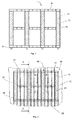
- Fig. 1 shows a frame (10) of the hanging fitting.
- the frame has got four uprights (11) with a loadlock strip (12) each, having a plurality of approximately circular through bore-holes (13). Further the frame contains three horizontal bars (15), whereof the uprights (11) are bonded with.
- One horizontal bar (15) is positioned at each end of the uprights (11), one horizontal bar (15) is positioned in the middle of the vertical dimension of the uprights (11).
- flanges (16) are designed at the horizontal bar (15), with which the frame can be connected to bearings in the container. In case, these bearings are fixed in the container, the frame (10) gains stability in the moment of inserting.
- 4 flanges (16) are shown. But it is also possible to provide more or less flanges (16).
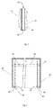
- Fig. 2 shows the frame (10) mounted in a standard freight container (20).
- the side walls of the container (20) exhibits indentations (21). These indentations (21) are approximately trapezoidal shaped.
- the horizontal bars (15) as well as the uprights (11) follow this form in order to capitalize the maximum inside width of the container.
- the frame (10) is supported by bearings (30), which are located in the indentations (21) of the sidewalls of the container (20).
- bearings (30) the same uprights (11) are used as for the frame (10).
- one bearing (30) is positioned in every indentation (21) of the container. But it is also possible to use only every second indentation (21) or even less indentations (21) of the container (20), depending on the load which is to be hung on the hanger bars (40).
- Fig. 3 is the cross-section A-A from Fig. 2 .
- a loadlock strip (12) with through bore-holes (13) is located in the indentation (21) of the container (20) in that way, that there is space (22) between the end of the though bore-hole evincible to the wall of the container (20) and the wall of the container (20) itself.
- Fig. 4 is a cross section through a container at an extend of an indentation with a mounted hanging fitting and one mounted hanger bar.
- the hanger bar (40) is one with the same dimension over its entire length. This dimension is that small that it fits in the through bore-holes (13) of the loadlock strip (12).
- the hanger bar is of the standard sprung loaded type. This is a telescopic rod, which can be pushed together against the force of a sprung. In the mounted case, the ends of the rod push against the walls of the container (20).
- the frame (10) is fixed at the walls of the container in vertically direction while being supported through bearings (30) (not visible). In horizontal direction they cannot collapse into the interior of the container due to the hanger bar (40) which is dived through the through bore-holes.
- the second embodiment is shown on the right hand side of the figure.
- the hanger bar (40) has got a bigger dimension than the inner dimension of the though bore-holes (13), and a shoulder (41) at both ends of the bar (40) with an outer part of the bar (40) with an outer dimension which fits in the through bore-holes (13).
- the longitudinal dimension of the outer part (42) with the smaller dimension of the bar is smaller than the distance of the front side, i.e. the side facing the interior of the container (20), of the loadlock strip to the container (20) wall it is mounted at. Therefore the hanger bar (40) with its shoulder (41) pushes the frames against the walls of the container (20).
- Fig. 5 is the cross section B-B of Fig. 2 .
- the upright (11) is mounted in the container (20) in such way that the loadlock strip (12) is positioned in a indentation (21) of the wall of the container (20).
- the loadlock strip (12) is shaped with a profile in that way, that there is space (22) between the loadlock strip (12) and the wall of the container (20), in which the hanger bars (40) can dive through the holes (13).
- Fig. 6 is the cross section C-C of Fig. 2 .
- a horizontal bar (15) is designed in a multi s-shape in that way that it fits in the indentations (21) of the wall of the container (20).
Landscapes
- Engineering & Computer Science (AREA)
- Mechanical Engineering (AREA)
- Holders For Apparel And Elements Relating To Apparel (AREA)
Abstract
Description
- The invention relates to a transport system for hanging transport of goods in a standard freight container with indentations in its sidewalls. Standard fright containers are well known in the state of the art and standardized in ISO 668. Such containers have got a cuboidal design and are produced out of steel plate. At least the side walls of such containers are designed with approximate trapezoidal indentations in order to increase stability. Said containers are used for transportation of general cargo, bulk load and the like. Such containers as such are not suitable for the shipping of hanging goods.
- In
US 3,561,634 a frame, which can be built in in a standard freight container is disclosed. This frame contains vertical bearings, which can be assembled in the inner corners of the containers by screwing them at the walls. Telescoping rods can be inserted lengthwise and crosswise in these rods in order to safeguard the load against shifting. Such rods could be used as hanger bars as well. The disadvantage of the systems consists in the fact that the vertical bearings have to be screwed at given screwing holes and positions. In case a plurality of crosswise hanger bars shall be provided, there have to be a plurality of vertical bearings as well due to stability reasons. In standard containers there are no such screwing holes at all, i.e. standard containers have to be upgraded. -
US 3,969,290 discloses a self-supporting assembly formed as a detachable replacement unit for hanging objects to be shipped, particularly garments, which is designed as a frame assembly with a plurality of parts such as perforated rails, suspensions rods and side members. The support frame is being braced within a container by means of spindle drives in such a manner that no fastening with the container itself is necessary thereby avoiding the necessity for structurally altering or damaging the walls of the container or leaving any visible signs of damage in any part of the container. The disadvantage of this system lies in the plurality of parts being used as well as in the time and effort to built in the frame into a container. Furthermore, the frame contains of horizontal, i.e. lengthwise built in perforated rails. These rails are connected to the vertical suspension rods and therefore reduce the utilizable inside width of the container. The system is not able to capitalize on the approximate trapezoidal indentations of the sidewalls of the container. - The objective of the invention is to provide a transport system for hanging transport of goods in a standard freight container, especially in rail freight containers, which can be easily inserted in and dismounted out of the standard freight container while making a maximum inside width of the container available for the shipped goods. A further objective of the invention is to provide a freight container for hanging transport of goods.
- According to the invention, the first objective is achieved by a device according to Claim 1. Advantageous embodiments of the device are set forth in the subordinate Claims 2 to 5. The further objective of the invention is achieved by a container having the features of claim 6.
- The advantage of the device according to the invention lies in the effective and reliable possibility of insertion and demounting of the frame as well as in the adaption of the design of the frame to the design of the side walls of standard containers in order to capitalize the maximum inner width of the container.
- The invention suggests a frame which is applicable at the walls of standard freight containers with indentations in its walls and which contains at least one upright with a loadlock strip having a plurality of holes for the seating of a hanger bar. The loadlock strips are shaped with a profile in that way, that the hanger bars can dive through the holes. The holes may have an approximately circular shape, but may also have other shapes, such as circles with excavations or notches or angled holes.
- The frame may contain further at least one horizontal bar, whereof the at least one upright with the loadlock strip is bonded with, which is designed in a multi s-shape in that way that it fits in the indentations of the standard freight container.
- In case, at least two frames, placed on opposite sides of the container in such way that pairs of the holes of the loadlock strips of the opposite frames are arranged in the same vertical distance from the container base, a hanger bar may be mounted in said holes that the hanger bar is in approximately parallel alignment to the container base. Goods hung at the hanger bar will not slip to one side but remain at the position they were hung up. If the hung goods are garments hung up on clothes hanger, these clothes hanger can be fastened at their position at the hanger bar with fastening systems which are known to persons skilled in the art, in order to avoid slipping during the transportation of the container.
- The frames may have a horizontal dimension as a fractional amount of the inner length of a standard freight container. It is an advantage that in this case the whole inside length of the standard container can be used for hanging up goods. For example, the horizontal dimension of the frames is an eighth of the inside length of a standard container, so that eight frames on each side of the container are used to line the whole length of the container with the frames. This means, that sixteen frames are needed for one standard container. Frames in such dimension are good manageable by workers. As an example, the frames may contain four uprights with loadlock strips each, so that thirty two hanger bars can be provided with one standard container.
- In an advantageous embodiment of the invention the holes have got an inner dimension, in which the outer dimension of standard sprung loaded hanger bars fit in.
- The frames may contain bearings for being supported from the base of the container. These bearings may be the same uprights like used for the frame or parts thereof. But other bearings are possible as well.
- In another embodiment, the bearings are separate from the frames, and may be located in the approximate trapezoidal indentations of the sidewalls. This implies the advantage that the frames can be built smaller, which facilitates the handling of the frames.
- There exist containers, especially rail fright containers, which contain uprights fixed in the indentations of its sidewalls for purpose of fixing goods with tension belts or the like. Such uprights have got a profile similar to the uprights of the frames and can be used as bearings for the hanging fitting. The frames may exhibit flanges at at least one horizontal bar with the aid of which the frames can be connected to said bearings. This facilitates the installation of the frames in the container until the first hanger bar is fixed.
- Possible as well is a combination of frames with one or more bearings with such ones without bearings. Such combination is advantageous in case a container is not fully equipped with fixed uprights in its indentations in the side walls.
- In a further advantageous embodiment the bearings are mounted to the frames in that way that they are telescopic. In case they are not needed or even objectionable, in case the container itself shows fixed bearings, they can drawn in the frame. For example they can be drawn behind the uprights of the frames in that way that the holes of the loadlock strip of the upright of the frame fall in line with the holes of the bearings, so that the hanger bars can dive through both the holes in the loadlock strips and the bearings. The advantage of such frames is that only one embodiment of frames is needed to equip all kinds of containers, irrespective whether or not they show bearings.
- The frames are fixed at the walls by the hanger bars, which may be sprung loaded. In one embodiment, the sprung bars have got a shoulder at each of their ends in order to fit in the holes of the loadlock strips on the one hand and to push apart the frames on the other hand. The longitudinal dimension of the shoulder is chosen in that way, that the hanger bar can dive with the crank though the hole in the loadlock strip on the one hand, but cannot touch the container side wall on the other hand. The longitudinal dimension of the shoulder is therefore smaller than the distance of the front side, i.e. the side facing the interior of the container, of the loadlock strip to the container wall it is mounted at.
- It is advantageous to secure the frames when being installed into the container and before the hanger bars are fixed. Standard containers usually show securing rings in the container roof. For securing the frames, chains with clippers at at least one end can be used by passing the chain through such ring on the one hand and clipping it on the frame on the other hand. Other possibilities for securing the frames with the aid of the securing rings are imaginable as well.
- The frames and hanger bars can be stored on trolleys in case they are not used or shall be shipped. In an advantageous embodiment of the invention, such trolley can be shipped in the same container as the hanging goods to be shipped with the aid of the transport system accordant to the invention. Such trolley may contain four swivel wheels with brake mechanisms, as known in the state of the art. Further such trolleys may show a rack capable to store at least sixteen frames and circa 80 hanger bars, which are needed to equip a standard container in total. In case the trolley is shipped with the same container as the hanging goods to be shipped with the aid of the transport system accordant to the invention, the frames and hanger bars can be sent back easily to the supplying depot without the need of sending back the same container.
- Additional advantages, special features and practical refinements of the invention can be gleaned from the subordinate claims and from the presentation below of preferred embodiments making reference to the figures.
- The figures show the following:
- Fig. 1
- frame of the hanging fitting
- Fig. 2.
- A hanging fitting mounted in a standard freight container.
- Fig. 3
- the cross section A-A from
Fig. 2 - Fig. 4
- a cross section through a container with mounted hanging fitting
- Fig. 5
- the cross section B-B from
Fig. 2 - Fig. 6
- the cross section C-C from
Fig. 2 -
Fig. 1 shows a frame (10) of the hanging fitting. The frame has got four uprights (11) with a loadlock strip (12) each, having a plurality of approximately circular through bore-holes (13). Further the frame contains three horizontal bars (15), whereof the uprights (11) are bonded with. One horizontal bar (15) is positioned at each end of the uprights (11), one horizontal bar (15) is positioned in the middle of the vertical dimension of the uprights (11). At the bottom side of the frame (10), flanges (16) are designed at the horizontal bar (15), with which the frame can be connected to bearings in the container. In case, these bearings are fixed in the container, the frame (10) gains stability in the moment of inserting. InFig. 1 ,4 flanges (16) are shown. But it is also possible to provide more or less flanges (16). -
Fig. 2 shows the frame (10) mounted in a standard freight container (20). The side walls of the container (20) exhibits indentations (21). These indentations (21) are approximately trapezoidal shaped. The horizontal bars (15) as well as the uprights (11) follow this form in order to capitalize the maximum inside width of the container. The frame (10) is supported by bearings (30), which are located in the indentations (21) of the sidewalls of the container (20). As bearings (30) the same uprights (11) are used as for the frame (10). InFig. 2 one bearing (30) is positioned in every indentation (21) of the container. But it is also possible to use only every second indentation (21) or even less indentations (21) of the container (20), depending on the load which is to be hung on the hanger bars (40). -
Fig. 3 is the cross-section A-A fromFig. 2 . A loadlock strip (12) with through bore-holes (13) is located in the indentation (21) of the container (20) in that way, that there is space (22) between the end of the though bore-hole evincible to the wall of the container (20) and the wall of the container (20) itself. -
Fig. 4 is a cross section through a container at an extend of an indentation with a mounted hanging fitting and one mounted hanger bar. There are two embodiments shown inFig. 4 : one the left hand side of the figure, the hanger bar (40) is one with the same dimension over its entire length. This dimension is that small that it fits in the through bore-holes (13) of the loadlock strip (12). The hanger bar is of the standard sprung loaded type. This is a telescopic rod, which can be pushed together against the force of a sprung. In the mounted case, the ends of the rod push against the walls of the container (20). The frame (10) is fixed at the walls of the container in vertically direction while being supported through bearings (30) (not visible). In horizontal direction they cannot collapse into the interior of the container due to the hanger bar (40) which is dived through the through bore-holes. - The second embodiment is shown on the right hand side of the figure. The hanger bar (40) has got a bigger dimension than the inner dimension of the though bore-holes (13), and a shoulder (41) at both ends of the bar (40) with an outer part of the bar (40) with an outer dimension which fits in the through bore-holes (13). The longitudinal dimension of the outer part (42) with the smaller dimension of the bar is smaller than the distance of the front side, i.e. the side facing the interior of the container (20), of the loadlock strip to the container (20) wall it is mounted at. Therefore the hanger bar (40) with its shoulder (41) pushes the frames against the walls of the container (20).
-
Fig. 5 is the cross section B-B ofFig. 2 . The upright (11) is mounted in the container (20) in such way that the loadlock strip (12) is positioned in a indentation (21) of the wall of the container (20). The loadlock strip (12) is shaped with a profile in that way, that there is space (22) between the loadlock strip (12) and the wall of the container (20), in which the hanger bars (40) can dive through the holes (13). -
Fig. 6 is the cross section C-C ofFig. 2 . A horizontal bar (15) is designed in a multi s-shape in that way that it fits in the indentations (21) of the wall of the container (20). -
- 10
- frame
- 11
- upright
- 12
- loadlock strip
- 13
- hole
- 15
- horizontal bar
- 16
- flange
- 20
- container
- 21
- indentation
- 22
- space
- 30
- bearing
- 40
- hanger bar
- 41
- shoulder
- 42
- part of the hanger bar with smaller dimension
Claims (6)
- Transport system for hanging transport of goods in a standard freight container (20) with indentations (21) in its sidewalls, containing a hanging fitting and a hanger bar (40),
characterized in, that
the hanging fitting contains a frame (10) which is applicable at the walls of the standard freight container (20) with its indentations (21) and which contains at least one upright (11) with a loadlock strip (12) having a plurality of holes (13) for the seating of the hanger bar (40). - Transport system according to claim 1,
characterized in, that
the frame (10) further contains at least one horizontal bar (15), whereof the at least one upright (11) with the loadlock strip (12) is bonded with, which is designed in a multi s-shape in that way that it fits in the indentations (21) of the walls of the standard freight container (20). - Transport system according to claim 1 or 2,
characterized in, that
the transport systems contains at least two frames (10), placed on opposite sides of the container (20) in such way that pairs of the-holes (13) of the loadlock strips (12) of the opposite frames (10) are arranged in the same vertical distance from the base of the container (20). - Transport system according to one or more of the previous claims,
characterized in, that
the frames (10) have got a horizontal dimension as a fractional amount of the inner length of a standard freight container (20), so that the whole length of a standard freight container (20) can be lined with the frames (10). - Transport system according to one or more of the previous claims,
characterized in, that
the hanger bar (40) is a standard sprung loaded hanger bar. - Freight container,
characterized in, that
the container (20) contains the hanging fittings and hanger bars (40) according to one of the previous claims.
Priority Applications (1)
| Application Number | Priority Date | Filing Date | Title |
|---|---|---|---|
| EP20100187789 EP2441703B1 (en) | 2010-10-15 | 2010-10-15 | Transport system for hanging goods in a freight container and freight container therewith |
Applications Claiming Priority (1)
| Application Number | Priority Date | Filing Date | Title |
|---|---|---|---|
| EP20100187789 EP2441703B1 (en) | 2010-10-15 | 2010-10-15 | Transport system for hanging goods in a freight container and freight container therewith |
Publications (2)
| Publication Number | Publication Date |
|---|---|
| EP2441703A1 true EP2441703A1 (en) | 2012-04-18 |
| EP2441703B1 EP2441703B1 (en) | 2014-07-02 |
Family
ID=43618938
Family Applications (1)
| Application Number | Title | Priority Date | Filing Date |
|---|---|---|---|
| EP20100187789 Not-in-force EP2441703B1 (en) | 2010-10-15 | 2010-10-15 | Transport system for hanging goods in a freight container and freight container therewith |
Country Status (1)
| Country | Link |
|---|---|
| EP (1) | EP2441703B1 (en) |
Citations (5)
| Publication number | Priority date | Publication date | Assignee | Title |
|---|---|---|---|---|
| US3506136A (en) * | 1968-01-25 | 1970-04-14 | Whittaker Corp | Removable rack for cargo containers |
| US3561634A (en) | 1968-09-11 | 1971-02-09 | Impetus Inc | Shipping container |
| DE2313712A1 (en) * | 1973-03-20 | 1974-09-26 | Birkart Int Johann | SUSPENSION EXTENSION, IN PARTICULAR FOR CONTAINERS OR BOX SUPPORTS FOR VEHICLES |
| US3969290A (en) | 1973-01-24 | 1976-07-13 | Hoechst Aktiengesellschaft | N,N'-substituted 2,4,5-triketoimidazolidines |
| WO1999055601A2 (en) * | 1998-04-25 | 1999-11-04 | Tibbett & Britten Group Plc | Container storage system |
-
2010
- 2010-10-15 EP EP20100187789 patent/EP2441703B1/en not_active Not-in-force
Patent Citations (5)
| Publication number | Priority date | Publication date | Assignee | Title |
|---|---|---|---|---|
| US3506136A (en) * | 1968-01-25 | 1970-04-14 | Whittaker Corp | Removable rack for cargo containers |
| US3561634A (en) | 1968-09-11 | 1971-02-09 | Impetus Inc | Shipping container |
| US3969290A (en) | 1973-01-24 | 1976-07-13 | Hoechst Aktiengesellschaft | N,N'-substituted 2,4,5-triketoimidazolidines |
| DE2313712A1 (en) * | 1973-03-20 | 1974-09-26 | Birkart Int Johann | SUSPENSION EXTENSION, IN PARTICULAR FOR CONTAINERS OR BOX SUPPORTS FOR VEHICLES |
| WO1999055601A2 (en) * | 1998-04-25 | 1999-11-04 | Tibbett & Britten Group Plc | Container storage system |
Also Published As
| Publication number | Publication date |
|---|---|
| EP2441703B1 (en) | 2014-07-02 |
Similar Documents
| Publication | Publication Date | Title |
|---|---|---|
| ES2790829T3 (en) | Shelf for a car | |
| US11046371B2 (en) | System for conveying and stowing elongated material | |
| US3963290A (en) | Hanging fitting for freight receptacles, known as containers | |
| US8596443B2 (en) | Goods feeding system for receiving and presenting goods | |
| US20140374190A1 (en) | Base for Supporting an Upstanding Mast | |
| ES2953472T3 (en) | A rail shelving system and a kit to convert a rack to a rail shelving system | |
| US6558102B2 (en) | High storage shelf system for hanging goods | |
| US5415299A (en) | Garment hanger support system | |
| CN103517858B (en) | The transport systems of large item | |
| EP2441703B1 (en) | Transport system for hanging goods in a freight container and freight container therewith | |
| EP3015400B1 (en) | A storage assembly for bulk bags | |
| US8985930B2 (en) | Plant for storing products | |
| US20170027320A1 (en) | Expandable wall storage system | |
| CN108216972B (en) | Container and container loading method | |
| EP2340978B1 (en) | A system for the mounting of shelves and the reduction of noise | |
| CN202244436U (en) | Tray | |
| US20130228661A1 (en) | Stabilizer shoe for a rack for supporting objects | |
| KR102627286B1 (en) | Merchandise display rack | |
| RU194452U1 (en) | DEVICE FOR CARRIAGE OF WHEELED VEHICLES | |
| SU1286103A3 (en) | Device for fastening cargoes | |
| US9775436B2 (en) | Shelf | |
| CN108657655B (en) | Suspension device for container, frame type gantry structure and container | |
| US20180305121A1 (en) | Method for constructing a carton flow bed rack and carton flow bed rack | |
| EP3372531A1 (en) | Supporting structure for a sliding rail | |
| CN111959971B (en) | Fixing device for open top container pallet and container assembly |
Legal Events
| Date | Code | Title | Description |
|---|---|---|---|
| PUAI | Public reference made under article 153(3) epc to a published international application that has entered the european phase |
Free format text: ORIGINAL CODE: 0009012 |
|
| AK | Designated contracting states |
Kind code of ref document: A1 Designated state(s): AL AT BE BG CH CY CZ DE DK EE ES FI FR GB GR HR HU IE IS IT LI LT LU LV MC MK MT NL NO PL PT RO RS SE SI SK SM TR |
|
| AX | Request for extension of the european patent |
Extension state: BA ME |
|
| 17P | Request for examination filed |
Effective date: 20121018 |
|
| GRAP | Despatch of communication of intention to grant a patent |
Free format text: ORIGINAL CODE: EPIDOSNIGR1 |
|
| INTG | Intention to grant announced |
Effective date: 20140117 |
|
| GRAS | Grant fee paid |
Free format text: ORIGINAL CODE: EPIDOSNIGR3 |
|
| GRAA | (expected) grant |
Free format text: ORIGINAL CODE: 0009210 |
|
| AK | Designated contracting states |
Kind code of ref document: B1 Designated state(s): AL AT BE BG CH CY CZ DE DK EE ES FI FR GB GR HR HU IE IS IT LI LT LU LV MC MK MT NL NO PL PT RO RS SE SI SK SM TR |
|
| REG | Reference to a national code |
Ref country code: GB Ref legal event code: FG4D |
|
| REG | Reference to a national code |
Ref country code: CH Ref legal event code: EP Ref country code: AT Ref legal event code: REF Ref document number: 675798 Country of ref document: AT Kind code of ref document: T Effective date: 20140715 |
|
| REG | Reference to a national code |
Ref country code: IE Ref legal event code: FG4D |
|
| REG | Reference to a national code |
Ref country code: DE Ref legal event code: R082 Ref document number: 602010017169 Country of ref document: DE Representative=s name: JOSTARNDT PATENTANWALTS-AG, DE |
|
| REG | Reference to a national code |
Ref country code: DE Ref legal event code: R096 Ref document number: 602010017169 Country of ref document: DE Effective date: 20140814 |
|
| REG | Reference to a national code |
Ref country code: NL Ref legal event code: T3 |
|
| REG | Reference to a national code |
Ref country code: AT Ref legal event code: MK05 Ref document number: 675798 Country of ref document: AT Kind code of ref document: T Effective date: 20140702 |
|
| REG | Reference to a national code |
Ref country code: LT Ref legal event code: MG4D |
|
| PG25 | Lapsed in a contracting state [announced via postgrant information from national office to epo] |
Ref country code: PT Free format text: LAPSE BECAUSE OF FAILURE TO SUBMIT A TRANSLATION OF THE DESCRIPTION OR TO PAY THE FEE WITHIN THE PRESCRIBED TIME-LIMIT Effective date: 20141103 Ref country code: SE Free format text: LAPSE BECAUSE OF FAILURE TO SUBMIT A TRANSLATION OF THE DESCRIPTION OR TO PAY THE FEE WITHIN THE PRESCRIBED TIME-LIMIT Effective date: 20140702 Ref country code: ES Free format text: LAPSE BECAUSE OF FAILURE TO SUBMIT A TRANSLATION OF THE DESCRIPTION OR TO PAY THE FEE WITHIN THE PRESCRIBED TIME-LIMIT Effective date: 20140702 Ref country code: NO Free format text: LAPSE BECAUSE OF FAILURE TO SUBMIT A TRANSLATION OF THE DESCRIPTION OR TO PAY THE FEE WITHIN THE PRESCRIBED TIME-LIMIT Effective date: 20141002 Ref country code: LT Free format text: LAPSE BECAUSE OF FAILURE TO SUBMIT A TRANSLATION OF THE DESCRIPTION OR TO PAY THE FEE WITHIN THE PRESCRIBED TIME-LIMIT Effective date: 20140702 Ref country code: CZ Free format text: LAPSE BECAUSE OF FAILURE TO SUBMIT A TRANSLATION OF THE DESCRIPTION OR TO PAY THE FEE WITHIN THE PRESCRIBED TIME-LIMIT Effective date: 20140702 Ref country code: FI Free format text: LAPSE BECAUSE OF FAILURE TO SUBMIT A TRANSLATION OF THE DESCRIPTION OR TO PAY THE FEE WITHIN THE PRESCRIBED TIME-LIMIT Effective date: 20140702 Ref country code: GR Free format text: LAPSE BECAUSE OF FAILURE TO SUBMIT A TRANSLATION OF THE DESCRIPTION OR TO PAY THE FEE WITHIN THE PRESCRIBED TIME-LIMIT Effective date: 20141003 Ref country code: BG Free format text: LAPSE BECAUSE OF FAILURE TO SUBMIT A TRANSLATION OF THE DESCRIPTION OR TO PAY THE FEE WITHIN THE PRESCRIBED TIME-LIMIT Effective date: 20141002 |
|
| PGFP | Annual fee paid to national office [announced via postgrant information from national office to epo] |
Ref country code: DE Payment date: 20141031 Year of fee payment: 5 |
|
| PG25 | Lapsed in a contracting state [announced via postgrant information from national office to epo] |
Ref country code: CY Free format text: LAPSE BECAUSE OF FAILURE TO SUBMIT A TRANSLATION OF THE DESCRIPTION OR TO PAY THE FEE WITHIN THE PRESCRIBED TIME-LIMIT Effective date: 20140702 Ref country code: AT Free format text: LAPSE BECAUSE OF FAILURE TO SUBMIT A TRANSLATION OF THE DESCRIPTION OR TO PAY THE FEE WITHIN THE PRESCRIBED TIME-LIMIT Effective date: 20140702 Ref country code: RS Free format text: LAPSE BECAUSE OF FAILURE TO SUBMIT A TRANSLATION OF THE DESCRIPTION OR TO PAY THE FEE WITHIN THE PRESCRIBED TIME-LIMIT Effective date: 20140702 Ref country code: LV Free format text: LAPSE BECAUSE OF FAILURE TO SUBMIT A TRANSLATION OF THE DESCRIPTION OR TO PAY THE FEE WITHIN THE PRESCRIBED TIME-LIMIT Effective date: 20140702 Ref country code: PL Free format text: LAPSE BECAUSE OF FAILURE TO SUBMIT A TRANSLATION OF THE DESCRIPTION OR TO PAY THE FEE WITHIN THE PRESCRIBED TIME-LIMIT Effective date: 20140702 Ref country code: IS Free format text: LAPSE BECAUSE OF FAILURE TO SUBMIT A TRANSLATION OF THE DESCRIPTION OR TO PAY THE FEE WITHIN THE PRESCRIBED TIME-LIMIT Effective date: 20141102 Ref country code: HR Free format text: LAPSE BECAUSE OF FAILURE TO SUBMIT A TRANSLATION OF THE DESCRIPTION OR TO PAY THE FEE WITHIN THE PRESCRIBED TIME-LIMIT Effective date: 20140702 |
|
| REG | Reference to a national code |
Ref country code: DE Ref legal event code: R097 Ref document number: 602010017169 Country of ref document: DE |
|
| PG25 | Lapsed in a contracting state [announced via postgrant information from national office to epo] |
Ref country code: RO Free format text: LAPSE BECAUSE OF FAILURE TO SUBMIT A TRANSLATION OF THE DESCRIPTION OR TO PAY THE FEE WITHIN THE PRESCRIBED TIME-LIMIT Effective date: 20140702 Ref country code: SK Free format text: LAPSE BECAUSE OF FAILURE TO SUBMIT A TRANSLATION OF THE DESCRIPTION OR TO PAY THE FEE WITHIN THE PRESCRIBED TIME-LIMIT Effective date: 20140702 Ref country code: DK Free format text: LAPSE BECAUSE OF FAILURE TO SUBMIT A TRANSLATION OF THE DESCRIPTION OR TO PAY THE FEE WITHIN THE PRESCRIBED TIME-LIMIT Effective date: 20140702 Ref country code: EE Free format text: LAPSE BECAUSE OF FAILURE TO SUBMIT A TRANSLATION OF THE DESCRIPTION OR TO PAY THE FEE WITHIN THE PRESCRIBED TIME-LIMIT Effective date: 20140702 Ref country code: IT Free format text: LAPSE BECAUSE OF FAILURE TO SUBMIT A TRANSLATION OF THE DESCRIPTION OR TO PAY THE FEE WITHIN THE PRESCRIBED TIME-LIMIT Effective date: 20140702 |
|
| PLBE | No opposition filed within time limit |
Free format text: ORIGINAL CODE: 0009261 |
|
| STAA | Information on the status of an ep patent application or granted ep patent |
Free format text: STATUS: NO OPPOSITION FILED WITHIN TIME LIMIT |
|
| PG25 | Lapsed in a contracting state [announced via postgrant information from national office to epo] |
Ref country code: LU Free format text: LAPSE BECAUSE OF FAILURE TO SUBMIT A TRANSLATION OF THE DESCRIPTION OR TO PAY THE FEE WITHIN THE PRESCRIBED TIME-LIMIT Effective date: 20141015 Ref country code: MC Free format text: LAPSE BECAUSE OF FAILURE TO SUBMIT A TRANSLATION OF THE DESCRIPTION OR TO PAY THE FEE WITHIN THE PRESCRIBED TIME-LIMIT Effective date: 20140702 |
|
| REG | Reference to a national code |
Ref country code: CH Ref legal event code: PL |
|
| 26N | No opposition filed |
Effective date: 20150407 |
|
| PG25 | Lapsed in a contracting state [announced via postgrant information from national office to epo] |
Ref country code: BE Free format text: LAPSE BECAUSE OF NON-PAYMENT OF DUE FEES Effective date: 20141031 |
|
| REG | Reference to a national code |
Ref country code: IE Ref legal event code: MM4A |
|
| PG25 | Lapsed in a contracting state [announced via postgrant information from national office to epo] |
Ref country code: LI Free format text: LAPSE BECAUSE OF NON-PAYMENT OF DUE FEES Effective date: 20141031 Ref country code: CH Free format text: LAPSE BECAUSE OF NON-PAYMENT OF DUE FEES Effective date: 20141031 |
|
| REG | Reference to a national code |
Ref country code: FR Ref legal event code: PLFP Year of fee payment: 6 |
|
| PG25 | Lapsed in a contracting state [announced via postgrant information from national office to epo] |
Ref country code: IE Free format text: LAPSE BECAUSE OF NON-PAYMENT OF DUE FEES Effective date: 20141015 |
|
| PG25 | Lapsed in a contracting state [announced via postgrant information from national office to epo] |
Ref country code: SI Free format text: LAPSE BECAUSE OF FAILURE TO SUBMIT A TRANSLATION OF THE DESCRIPTION OR TO PAY THE FEE WITHIN THE PRESCRIBED TIME-LIMIT Effective date: 20140702 |
|
| PGFP | Annual fee paid to national office [announced via postgrant information from national office to epo] |
Ref country code: GB Payment date: 20151021 Year of fee payment: 6 |
|
| PGFP | Annual fee paid to national office [announced via postgrant information from national office to epo] |
Ref country code: FR Payment date: 20151023 Year of fee payment: 6 Ref country code: NL Payment date: 20151021 Year of fee payment: 6 |
|
| PG25 | Lapsed in a contracting state [announced via postgrant information from national office to epo] |
Ref country code: SM Free format text: LAPSE BECAUSE OF FAILURE TO SUBMIT A TRANSLATION OF THE DESCRIPTION OR TO PAY THE FEE WITHIN THE PRESCRIBED TIME-LIMIT Effective date: 20140702 |
|
| REG | Reference to a national code |
Ref country code: DE Ref legal event code: R119 Ref document number: 602010017169 Country of ref document: DE |
|
| PG25 | Lapsed in a contracting state [announced via postgrant information from national office to epo] |
Ref country code: TR Free format text: LAPSE BECAUSE OF FAILURE TO SUBMIT A TRANSLATION OF THE DESCRIPTION OR TO PAY THE FEE WITHIN THE PRESCRIBED TIME-LIMIT Effective date: 20140702 Ref country code: DE Free format text: LAPSE BECAUSE OF NON-PAYMENT OF DUE FEES Effective date: 20160503 Ref country code: MT Free format text: LAPSE BECAUSE OF FAILURE TO SUBMIT A TRANSLATION OF THE DESCRIPTION OR TO PAY THE FEE WITHIN THE PRESCRIBED TIME-LIMIT Effective date: 20140702 Ref country code: HU Free format text: LAPSE BECAUSE OF FAILURE TO SUBMIT A TRANSLATION OF THE DESCRIPTION OR TO PAY THE FEE WITHIN THE PRESCRIBED TIME-LIMIT; INVALID AB INITIO Effective date: 20101015 Ref country code: BE Free format text: LAPSE BECAUSE OF FAILURE TO SUBMIT A TRANSLATION OF THE DESCRIPTION OR TO PAY THE FEE WITHIN THE PRESCRIBED TIME-LIMIT Effective date: 20140702 |
|
| REG | Reference to a national code |
Ref country code: NL Ref legal event code: MM Effective date: 20161101 |
|
| GBPC | Gb: european patent ceased through non-payment of renewal fee |
Effective date: 20161015 |
|
| REG | Reference to a national code |
Ref country code: FR Ref legal event code: ST Effective date: 20170630 |
|
| PG25 | Lapsed in a contracting state [announced via postgrant information from national office to epo] |
Ref country code: FR Free format text: LAPSE BECAUSE OF NON-PAYMENT OF DUE FEES Effective date: 20161102 Ref country code: GB Free format text: LAPSE BECAUSE OF NON-PAYMENT OF DUE FEES Effective date: 20161015 |
|
| PG25 | Lapsed in a contracting state [announced via postgrant information from national office to epo] |
Ref country code: NL Free format text: LAPSE BECAUSE OF NON-PAYMENT OF DUE FEES Effective date: 20161101 |
|
| PG25 | Lapsed in a contracting state [announced via postgrant information from national office to epo] |
Ref country code: MK Free format text: LAPSE BECAUSE OF FAILURE TO SUBMIT A TRANSLATION OF THE DESCRIPTION OR TO PAY THE FEE WITHIN THE PRESCRIBED TIME-LIMIT Effective date: 20140702 |
|
| PG25 | Lapsed in a contracting state [announced via postgrant information from national office to epo] |
Ref country code: AL Free format text: LAPSE BECAUSE OF FAILURE TO SUBMIT A TRANSLATION OF THE DESCRIPTION OR TO PAY THE FEE WITHIN THE PRESCRIBED TIME-LIMIT Effective date: 20140702 |