EP2441670B1 - Ailette entraînée vers l'avant - Google Patents
Ailette entraînée vers l'avant Download PDFInfo
- Publication number
- EP2441670B1 EP2441670B1 EP11183673.0A EP11183673A EP2441670B1 EP 2441670 B1 EP2441670 B1 EP 2441670B1 EP 11183673 A EP11183673 A EP 11183673A EP 2441670 B1 EP2441670 B1 EP 2441670B1
- Authority
- EP
- European Patent Office
- Prior art keywords
- wing
- winglet
- aircraft
- swept
- tip
- Prior art date
- Legal status (The legal status is an assumption and is not a legal conclusion. Google has not performed a legal analysis and makes no representation as to the accuracy of the status listed.)
- Active
Links
- 238000000034 method Methods 0.000 claims description 10
- 230000008901 benefit Effects 0.000 description 6
- 230000033001 locomotion Effects 0.000 description 6
- 238000005452 bending Methods 0.000 description 5
- 230000002349 favourable effect Effects 0.000 description 5
- 210000003746 feather Anatomy 0.000 description 5
- RZVHIXYEVGDQDX-UHFFFAOYSA-N 9,10-anthraquinone Chemical compound C1=CC=C2C(=O)C3=CC=CC=C3C(=O)C2=C1 RZVHIXYEVGDQDX-UHFFFAOYSA-N 0.000 description 4
- 239000000446 fuel Substances 0.000 description 4
- 239000003381 stabilizer Substances 0.000 description 4
- 230000005484 gravity Effects 0.000 description 3
- 230000009467 reduction Effects 0.000 description 2
- NRTLIYOWLVMQBO-UHFFFAOYSA-N 5-chloro-1,3-dimethyl-N-(1,1,3-trimethyl-1,3-dihydro-2-benzofuran-4-yl)pyrazole-4-carboxamide Chemical compound C=12C(C)OC(C)(C)C2=CC=CC=1NC(=O)C=1C(C)=NN(C)C=1Cl NRTLIYOWLVMQBO-UHFFFAOYSA-N 0.000 description 1
- 230000001133 acceleration Effects 0.000 description 1
- 230000006978 adaptation Effects 0.000 description 1
- 238000013459 approach Methods 0.000 description 1
- 238000007796 conventional method Methods 0.000 description 1
- 238000013461 design Methods 0.000 description 1
- 230000007246 mechanism Effects 0.000 description 1
- 230000010355 oscillation Effects 0.000 description 1
- 230000004044 response Effects 0.000 description 1
- 238000012552 review Methods 0.000 description 1
- 238000010408 sweeping Methods 0.000 description 1
- 230000007704 transition Effects 0.000 description 1
Images


Classifications
-
- B—PERFORMING OPERATIONS; TRANSPORTING
- B64—AIRCRAFT; AVIATION; COSMONAUTICS
- B64C—AEROPLANES; HELICOPTERS
- B64C23/00—Influencing air flow over aircraft surfaces, not otherwise provided for
- B64C23/06—Influencing air flow over aircraft surfaces, not otherwise provided for by generating vortices
- B64C23/065—Influencing air flow over aircraft surfaces, not otherwise provided for by generating vortices at the wing tips
- B64C23/069—Influencing air flow over aircraft surfaces, not otherwise provided for by generating vortices at the wing tips using one or more wing tip airfoil devices, e.g. winglets, splines, wing tip fences or raked wingtips
-
- Y—GENERAL TAGGING OF NEW TECHNOLOGICAL DEVELOPMENTS; GENERAL TAGGING OF CROSS-SECTIONAL TECHNOLOGIES SPANNING OVER SEVERAL SECTIONS OF THE IPC; TECHNICAL SUBJECTS COVERED BY FORMER USPC CROSS-REFERENCE ART COLLECTIONS [XRACs] AND DIGESTS
- Y02—TECHNOLOGIES OR APPLICATIONS FOR MITIGATION OR ADAPTATION AGAINST CLIMATE CHANGE
- Y02T—CLIMATE CHANGE MITIGATION TECHNOLOGIES RELATED TO TRANSPORTATION
- Y02T50/00—Aeronautics or air transport
- Y02T50/10—Drag reduction
Definitions
- the present disclosure relates to aircraft, and more particularly to a forward swept winglet for an aircraft wing.
- L/D ratio lift-to-drag ratio
- One method to improve the L/D ratio of an airplane is to use a wing of greater span or length and shorter chord or distance from a leading edge of the wing to a trailing edge of the wing. In other words a wing with greater aspect ratio will have a higher L/D ratio and will be more efficient.
- Aspect ratio is defined as the wing span squared divided by the wing area.
- One limitation may be airport compatibility. Airports may be designed for airplanes with a certain maximum wing span. To operate at an airport, each airplane must have a wing span that is less than or equal to the maximum for the particular airport.
- wing weight Another possible limitation may be wing weight.
- the use of a high aspect ratio wing can increase the airplane's L/D ratio but may not result in lower drag and may not result in less fuel consumption. Because the wing is a structural element, increasing its length increases the bending load the wing must resist. Accordingly the wing structure must be stronger or more robust to resist the bending load. The increased structure increases the wing's weight. Thus, a higher aspect ratio may result in a heavier airplane. Because drag is equal to airplane weight divided by the L/D ratio, a higher airplane weight may result in increased drag even if the L/D ratio is increased. In practice, wing aspect ratios are set to a value that results in minimum drag, or the aspect ratios are set to lower values that result in a significantly lighter airplane with drag that is slightly greater than minimum.
- Wing flutter is a dynamic phenomenon in which an approximately vertical (flapping) motion of the wing couples with a torsional mode (wing twist), resulting in unacceptable shaking in the wing that can cause structural damage. Wings can become more limber at higher aspect ratios which can lead to greater flutter susceptibility. This relationship sometimes limits the wing aspect ratio.
- FIG. 1 illustrates an aircraft 100 including wings 102 and an aft-swept winglet 104 attached to a wing tip of each wing 102.
- the winglet 104 may provide the benefit of increased wing span without actually increasing the wing span.
- Winglets 104 may also reduce the bending load on the wing 102 compared to a conventional wing having an equivalent L/D ratio, thereby reducing the weight penalty of a wing with a larger span.
- aft-swept winglets 104 may result in increased flutter susceptibility.
- winglets 104 The aerodynamic benefit of winglets 104 is increased with increased winglet span, "S,” or distance from a root 106 of the winglet 104 to a tip 108 of the winglet 104, but the structural and especially flutter susceptibility increases rapidly with winglet span. Thus flutter concerns tend to limit winglet span.
- the wing may be considered to be a torsional pendulum. Resistance to torsion is typically provided by the box or tube-like structure of the wing. Given the torsional rigidity provided by this structure, the frequency is primarily determined by the polar distribution of mass about a torsional axis 110 of the wing structure as well as a spanwise distribution of this mass.
- a torsional pendulum consisting of a thin vertical rod fixed to the clock at the top and free at the bottom. At the bottom of this rod a small dumbbell is attached.
- the rod When this dumbbell is rotated about the axis of the rod, the rod provides torsional resistance. When the dumbbell is released, the dumbbell oscillates at a certain frequency according to its polar moment of inertia about the rod's axis and the rigidity of the rod. An increase in inertia reduces the frequency. Moving the dumbbell to a point midway on the rod will result in an increased frequency because of the higher effective rigidity of the rod. Longer winglets tend to have greater polar moment of inertia by virtue of their greater weight and greater length.
- wing flutter susceptibility Another factor affecting wing flutter susceptibility is the rearward offset of the wing's mass with respect to the torsional axis 110 of the wing's structure.
- the wing flies through the air, it makes lift that is proportional to its angle of attack. Increased lift tends to drive the wing upward, especially the outer portion of the wing. For instance, flying into an upward gust of air directly increases the wing's angle of attack which increases its lift which results in an upward acceleration, resulting in an upward deflection. If the center of mass of the wing is behind the torsional axis of the wing, then this upward gust will result in the wing twisting to a higher angle of incidence.
- Aft-swept winglets such as winglets 104
- aft-swept winglets 104 add weight behind the wing's torsional axis 110 and this weight is also added at the wing tip.
- Increasing the span of aft-swept winglets 104 may also increase the polar moment of inertia and moves the wing's center of mass aft. Thus, longer winglets may further increase flutter by the two mechanisms described above.
- Winglets may sweep up from the wing tip or may sweep down, or both.
- the aerodynamic benefit is approximately driven by the distance from the top of the upper winglet to the bottom of the lower winglet. From a flutter standpoint, the increase in polar moment of inertia would benefit from the upper and lower winglets having the same span. This puts the center of mass of the upper and lower winglets closer to the wing's torsional axis 110. Also, the center of mass of the winglets as a system is farther forward than if only a single winglet of the same span is used.
- a system is disclosed as including an aircraft wing having an inboard portion, an outboard portion, and a leading edge having an aft wing sweep angle at the outboard portion.
- a first feather is fixed relative to, and projects outwardly from, the outboard portion of the wing and has a leading edge with a first, forward sweep angle relative to a pitch axis of the wing.
- a second feather is fixed relative to, and projects outwardly from, the outboard portion of the wing at least partially aft of the first feather, and has a leading edge with a second, aft sweep angle relative to the pitch axis.
- an aircraft may include a pair of wings.
- a forward swept winglet may be attached proximate to a wing tip of each wing.
- the forward swept winglet may include a leading edge and a trailing edge.
- the leading edge of each winglet may extend from the wing at a predetermined forward sweep angle relative to a line perpendicular to a chord of the wing tip in a direction corresponding to a forward portion of the aircraft.
- an aircraft may include a wing and a forward swept winglet attached proximate to a wing tip of the wing.
- the forward swept winglet may include an upper winglet portion extending above the wing and a lower winglet portion extending below the wing.
- a leading edge of at least the upper winglet portion may extend from the wing at a predetermined forward sweep angle relative to a line perpendicular to a chord of the wing tip in a direction corresponding to a forward portion of the aircraft.
- a method to reduce wing flutter in an aircraft wing designed to provide a substantially increased lift-to-drag ratio may include attaching a forward swept winglet proximate to a wing tip of each wing of the aircraft.
- the forward swept winglet may include a leading edge and a trailing edge.
- the leading edge of each winglet may extend at a predetermined forward sweep angle relative to a line perpendicular to a chord of the wing tip in a direction corresponding to a forward portion of the aircraft.
- an aircraft comprising: a wing; and a forward swept winglet attached proximate to a wing tip of the wing, the forward swept winglet comprising an upper winglet portion extending above the wing and a lower winglet portion extending below the wing, a leading edge of at least the upper winglet portion extending from the wing at a predetermined forward sweep angle relative to a line perpendicular to a chord of the wing tip in a direction corresponding to a forward portion of the aircraft.
- the lower winglet portion includes a leading edge and a trailing edge, the leading edge of the lower winglet portion extending from the wing at a selected forward sweep angle relative to the line perpendicular to the chord of the wing tip in a direction toward the forward portion of the aircraft.
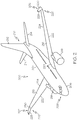
- FIG 2 is an illustration of an aircraft 200 including upper forward swept winglets 202 in accordance with an exemplary embodiment of the present disclosure.
- the aircraft 200 may also include only lower forward swept winglets which may have similar characteristics to those described herein.
- the aircraft 200 may include a forward swept winglet including both an upper winglet portion and a lower winglet portion.
- An exemplary embodiment of an aircraft including a forward swept winglet including both upper and lower winglet portions will be described in more detail with reference to Figures 6 , 7A-7C and 10 .
- the aircraft 200 includes an elongate fuselage 204.
- the elongate fuselage 204 includes a nose or forward portion 206 of the fuselage 204 or aircraft 200, where a cockpit 208 is located, and an aft or tail portion 210 of the aircraft 200 where a vertical stabilizer and rudder flight control surface 212 are mounted and a horizontal stabilizer and elevator flight control surface 214 are mounted.
- the rudder 212 controls right and left motion of the aircraft 200 and the elevator 214 controls up and down or altitude of the aircraft 200.
- a wing 216 is attached to each side of the fuselage 204 and extends from the fuselage 204.
- the exemplary aircraft 200 illustrated in Figure 2 has engines 218 mounted under each wing 216; although as known in the art, the engines 218 may be mounted at other locations on the aircraft 200, such as proximate to the tail section 210 above the wing 216 or other locations depending upon the aircraft design.
- Each wing 216 may be attached to the fuselage 204 at a wing root 220.
- Each wing 216 includes a leading edge 222 and trailing edge 224 extending from the wing root 220 to a wing tip 226 opposite to the wing root 220.
- a forward swept winglet 202 is attached proximate to the wing tip 226 of each wing 216.
- the forward swept winglet 202 may be attached at the wing tip 226 as illustrated in the exemplary embodiment in Figure 2 or, in another embodiment, the winglet 202 may be attached at a predetermined distance from the wing tip 226 toward the wing root 220.
- Figure 3A is a detailed side elevation view of the upper forward swept winglet 202 of Figure 2 in accordance with an exemplary embodiment of the present disclosure.
- the forward swept winglet 202 includes a leading edge 228 and a trailing edge 230.
- the leading edge 228 and trailing edge 230 may extend from a root 232 of the winglet 202 to a tip 234 of the winglet 202.
- the leading edge 228 and the trailing edge 230 may have a selected taper from the winglet root 232 to the winglet tip 234.
- each winglet 202 may extend from the wing 216 or wing tip 226 at a predetermined forward sweep angle ⁇ relative to a line 235 perpendicular or normal to a chord 236 of the wing tip 226 or wing 216 in a direction corresponding to the forward portion 206 of the aircraft 200.
- the chord 236 may be defined as the distance between the leading edge 222 and the trailing edge 224 of the wing 216 or wing tip 226.
- the chord 236 is illustrated by a broken or chain line in Figure 3A .
- the trailing edge 230 of the winglet 202 may also extend from the wing 216 or wing tip 226 at a selected forward sweep angle ⁇ relative to another line 238 perpendicular to the chord 236 of the wing 216 or wing tip 226.
- the selected forward sweep angle ⁇ of the trailing edge 230 of the winglet 202 may be greater than the predetermined forward sweep angle ⁇ of the leading edge 228 of the winglet 202 to provide the selected taper of the winglet 202.
- the selected forward sweep angle ⁇ of the trailing edge 230 may be less than the predetermined forward sweep angle ⁇ of the leading edge 228.
- the selected sweep angle ⁇ may even sweep toward an aft or tail portion 210 of the aircraft 200 ( Figure 2 ).
- the predetermined forward sweep angle ⁇ of the leading edge 228 and selected forward sweep angle ⁇ may vary. Considerations or parameters in determining the forward sweep angles may include but is not necessarily limited to a weight of the winglet; a wing span and area of each wing and winglet; a cruise Mach number at which the aircraft may be expected or designed to fly; any balancing mass or balancing mass weight in the winglet 202; and reducing induced drag of the winglet 202 or wing system including the wing 216 and winglet 202.
- the predetermined forward sweep angle ⁇ of the leading edge 228 of the winglet 202 may be greater than about 15 degrees and less than about 50 degrees.
- the forward swept winglet 202 may be built using conventional methods to be of typically light weight.
- the winglet 202 may also include discrete a weight 240 for mass balance.
- the mass balance weight 240 or weights may be located at favorable locations in the winglet 202 for optimum distribution of mass balance. One potentially favorable location may be proximate the leading edge 228 and proximate the tip 234 of the forward swept winglet 202 similar to that illustrated in Figure 3A .
- the weight of the forward swept winglet 202 is located ahead or forward of the weight of a similar aft-swept winglet, such as winglet 104 in Figure 1 . This more forward weight may reduce susceptibility to wing flutter when compared to a wing with an equivalent aft-swept winglet or a wing without a winglet.
- the forward swept winglet 202 may be used to mount a mass balance weight 240 at a favorable location such as near the leading edge 228 and near the tip 234. This mass balance 240 is well ahead or forward of the wing's torsional axis 242. This mass balance 240 further tends to suppress susceptibility to wing flutter.
- a chord of the forward swept winglet 202 may be substantially equal in length and correspond or align with the chord 236 of the wing 216 or wing tip 226.
- Figure 3B is a detailed side elevation view of an upper forward swept winglet 300 in accordance with another exemplary embodiment of the present disclosure.
- the upper forward winglet 300 may be substantially the same as the upper forward winglet 202 in Figure 3A except that a leading edge 228 of the winglet 300 is offset a selected distance "DA" from the leading edge 222 of the wing 216 or wing tip 226 in an aft direction. Described another way, a root or root chord 302 of the winglet 300 is attached to the wing tip 226 or wing 216 offset the selected distance "DA" relative to the chord 236 of the wing tip 226 or wing 216 in the aft direction.
- the remaining chord distribution of the winglet 300 may be determined by conventional aerodynamic considerations.
- FIG 3C is a detailed side elevation view of an upper forward swept winglet 301 in accordance with a further exemplary embodiment of the present disclosure.
- the upper forward winglet 301 may also be substantially the same as the upper forward winglet 202 in Figure 3A except that a leading edge 228 of the winglet 301 is offset a selected distance "DF" from the leading edge 222 of the wing 216 or wing tip 226 in an forward direction. Described another way, a root or root chord 303 of the winglet 301 is attached to the wing tip 226 or wing 216 offset the selected distance "DF" relative to the chord 236 of the wing tip 226 or wing 216 in the forward direction.
- the remaining chord distribution of the winglet 301 may be determined by conventional aerodynamic considerations.
- Figure 4 is a detailed front elevation view of the upper forward swept winglet 202 illustrating the winglet extending from the wing tip 226 substantially perpendicular to the wing 216 of the aircraft 200 in accordance with an exemplary embodiment of the present disclosure.
- Figure 5 is a detailed front elevation view of the upper forward swept winglet 202 extending from the wing tip 226 at a chosen angle I relative to the wing 216 of the aircraft in accordance with another exemplary embodiment of the present disclosure.
- Figures 4 and 5 illustrate that the forward swept winglet 202 may extend from wing 216 at a chosen angle I in a direction inboard toward the fuselage 204 ( Figure 1 ) or outboard away from the fuselage.
- the chosen angle I may be between about 45 degrees and about 135 degrees.
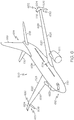
- FIG. 6 is an illustration of an aircraft 600 including a forward swept winglet 602 including an upper forward swept winglet portion 604 and a lower forward swept winglet portion 606 in accordance with another exemplary embodiment of the present disclosure.
- the aircraft 600 may be similar to the aircraft 200 in Figure 2 .
- the aircraft 600 includes an elongate fuselage 608.
- the elongate fuselage 608 includes a nose or forward portion 610, where a cockpit 612 is located, and an aft or tail portion 614 of the aircraft 600.
- a vertical stabilizer and rudder flight control surface 616 and a horizontal stabilizers and elevator flight control surface 618 are mounted to the aft or tail portion 614 of the aircraft 600.
- a wing 620 is attached to each side of the fuselage 608 and extends from the fuselage 608.
- the exemplary aircraft 600 illustrated in Figure 6 has engines 622 mounted under each wing 220; although as known in the art and as previously described, the engines 622 may be mounted at other locations on the aircraft 600.
- Each wing 620 may be attached to the fuselage 608 at a wing root 624.
- Each wing 620 includes a leading edge 626 and trailing edge 628 extending from the wing root 624 to a wing tip 630 opposite to the wing root 624.
- the forward swept winglet 602 may be attached to the wing tip 630 or to the wing 620 proximate to the wing tip 630.
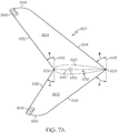
- Figure 7A is a detailed side elevation view of the forward swept winglet 602 of Figure 6 including the upper and lower winglet portions 604 and 606 in accordance with an exemplary embodiment of the present disclosure.
- the upper winglet portion 604 extends above the wing 620 or wing tip 630 and the lower winglet portion 606 extends below the wing 620 or wing tip 630.
- the upper winglet portion 604 includes a leading edge 632 and a trailing edge 634.
- the lower winglet portion 606 includes a leading edge 636 and a trailing edge 638.
- the leading edge 632 of at least the upper winglet portion 604 may extend from the wing 620 or wing tip 630 at a predetermined forward sweep angle ⁇ relative to a line 642 perpendicular to the chord 640 of the wing tip 630 in a direction corresponding to the forward portion 610 of the aircraft 600.
- the leading edge 636 of the lower winglet portion 606 may also extend from the wing 620 or wing tip 630 at a selected forward angle ⁇ relative to the perpendicular line 642 to the chord 640 of the wing 620 in a direction toward the forward portion 610 of the aircraft 600.
- the selected forward sweep angle ⁇ of the leading edge 636 of the lower winglet portion 606 may be different than the predetermined forward sweep angle ⁇ of the upper winglet portion 604. While the lower winglet portion 606 is illustrated in the exemplary embodiment in Figure 7A as sweeping forward, in another embodiment, the lower winglet portion 606 may sweep aft or may not sweep in either direction.
- the trailing edge 634 of the upper winglet portion 604 may sweep forward at a chosen sweep angle ⁇ relative to another line 643 perpendicular to the chord 630 of the wing 620 or wing tip 630.
- the chosen sweep angle ⁇ may be different from the predetermined sweep angle ⁇ of the leading edge 632 of the upper winglet portion 604 and the selected sweep angle ⁇ the leading edge 636 of the lower winglet portion.
- the chosen sweep angle ⁇ of the trailing edge 634 may be greater than the predetermined sweep angle ⁇ of the leading edge 632 of the upper winglet portion 604 so that the upper winglet portion tapers toward a tip 644 of the upper winglet portion 604.
- the chosen sweep angle ⁇ of the trailing edge 634 may be less than the predetermined sweep angle ⁇ of the leading edge 632 of the upper winglet portion 604 so that the upper winglet portion widens toward a tip 644 of the upper winglet portion 604.
- the trailing edge 638 of the lower winglet portion 606 may extend from the wing 620 or wing tip 630 at a predetermined angle ⁇ which may be less than, equal to or greater than the chosen angle ⁇ of the leading edge 636.
- the upper winglet portion 604 and the lower winglet portion 606 may each include a mass balance weight 646 and 648 respectively or only one of the winglet portions may include a mass balance weight.
- the mass balance weight 646 and 648 may be located at predetermined favorable locations in each of the upper and lower winglet portions 604 and 606. One potential favorable location in each winglet portion 604 and 606 may be proximate to the leading edge 632 and 636 and proximate to the tip 644 and 650. Thus, a mass balance of a chosen weight may be positioned at a farthest forward position of each of the upper and lower winglet portions 604 and 606. The optimum amount of mass balance 646 and 648 in each winglet portion 604 and 606 may be different.
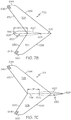
- FIG 7B is a detailed side elevation view of a forward swept winglet 700 including upper and lower winglet portions 702 and 704 in accordance with another exemplary embodiment of the present disclosure.
- the forward winglet 700 may be substantially the same as the forward winglet 702 in Figure 7A except that a leading edge 632 of the upper winglet portion 702 and the leading edge 636 of the lower winglet portion 704 are offset a selected distance "DA" from the leading edge 626 of the wing 620 or wing tip 630 in an aft direction.
- DA selected distance
- a root or root chord 706 of the winglet 700 is attached to the wing tip 630 or wing 620 offset the selected distance "DA" relative to the chord 640 of the wing tip 630 or wing 620 in the aft direction.
- the remaining chord distribution of the winglet 700 may be determined by conventional aerodynamic considerations. While the leading edges 632 and 634 are illustrated in Figure 7B as being offset by the same distance "DA" from the leading edge of the wing 620, the leading edges 632 and 634 may be offset by different distances. One or the other of the leading edges 632 and 636 may even be forward of the leading edge 626 of the wing 620 similar to that illustrated in Figure 7C .
- FIG. 7C is a detailed side elevation view of a forward swept winglet 701 including upper and lower winglet portions 703 and 705 in accordance with a further exemplary embodiment of the present disclosure.
- the forward swept winglet 701 may also be substantially the same as the forward swept winglet 602 in Figure 7A except that the leading edges 632 and 636 of the upper and lower winglet portions 703 and 705 are offset a selected distance "DF" from the leading edge 626 of the wing 620 or wing tip 630 in an forward direction.
- a root or root chord 706 of the winglet 701 is attached to the wing tip 630 or wing 620 offset the selected distance "DF" relative to the chord 640 of the wing tip 630 or wing 620 in the forward direction.
- the remaining chord distribution of the winglet 701 may be determined by conventional aerodynamic considerations.
- Figure 8 is a detailed front elevation view of the forward swept winglet 602 including upper and lower winglet portions 604 and 606 extending substantially perpendicular to the wing 620 of the aircraft 600 in accordance with an exemplary embodiment of the present disclosure.
- Figure 9 is a detailed front elevation view of the forward swept winglet 602 including upper and lower winglet portions 604 and 606 extending at predetermined angles I and ⁇ relative to the wing 620 of the aircraft 620 in accordance with another embodiment of the present disclosure.
- Figures 8 and 9 illustrate that each of the winglet portions 604 and 606 of the winglet 602 may extend from wing 620 at the same or a different predetermined angles I and ⁇ in a direction inboard toward the fuselage 608 ( Figure 6 ) or outboard away from the fuselage 608.
- the predetermined angles I and ⁇ may be between about 45 degrees and about 135 degrees.
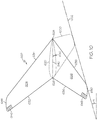
- FIG 10 is a detailed side elevation view of the forward swept winglet 602 including upper and lower winglet portions 604 and 606 illustrating a comparison of ground clearance for forward and aft swept lower winglet portions in accordance with an exemplary embodiment of the present disclosure.
- An aft-swept winglet 1000 is shown by a dotted line and ground clearance is represented in Figure 10 by the chain line 1002.
- the ground clearance 1002 is illustrated at an angle A relative to horizontal to represent the orientation of the winglet 602 and the aft-swept winglet 1000 when the aircraft 600 rotates into a nose up position for take off or landing.
- a forward swept lower winglet portion 606 may have a much longer span compared to the aft-swept winglet 1000.
- the structure of the forward swept winglet 202 and 602 as illustrated in Figures 3A and 7A function to increase the aerodynamic efficiency of the wing 216 ( Figure 2 ) and 620 ( Figure 6 ).
- the winglet 202 and 602 influences a greater mass of air flowing over the wing 216 and 620. This reduces the downwash angle and induced drag of the wing. This benefit is sensitive primarily to the ratio of the height of the winglet (upper tip to lower tip) to the wing span.
- the forward swept winglets 202 and 602 also serve to move the center of mass of the outer portion of the wing forward. Moving the center of mass of the wing forward is intended to reduce the wings susceptibility to flutter as previously described.
- the winglets 202 and 602 add mass to the wing tip that is forward of the torsional axis 242 ( Figure 3A ) and 650 ( Figure 7A ) of the wing 216 and 620. This may be accomplished by the weight of the winglet itself being forward of the torsional axis 242 and 650 and a mass balance may be located in the winglet 202 and 602 as described herein to add additional mass as far forward as possible from the wing torsional axis 242 and 650.
- a center of gravity of the winglet 202 may be adjusted or a center of gravity of each of the upper winglet portion 604 and lower winglet portion 606 may be adjusted vertically. In this way, the response of the wing may be tuned to fore and aft motion of the wing and to reduce susceptibility to wing flutter.
- the tuning may involve varying the span of the upper and lower winglet portions. A longer upper winglet portion span with a shorter lower winglet span tends to move the entire winglet center of gravity upwards.
- Tuning may also involve adjusting the mass balance in the upper and lower winglet portions. For example increasing the mass balance in the upper winglet while reducing the mass balance in the lower winglet portion may move the entire winglet's center of mass upward.
- a forward swept winglet may achieve different results.
- a lower forward swept winglet may achieve the ground clearance illustrated in Figure 10 along with the other features describe herein.
- a forward swept lower winglet could be used with an aft swept upper winglet to achieve a larger winglet span.
- a forward swept upper winglet could be combined with an aft swept lower winglet, especially when the upper winglet contains a mass balance weight to provide some benefits of a forward swept winglet with reduced yaw torque on the outer wing box or structure resulting from an airplane side slip in flight.
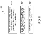
- FIG 11 is a flow chart of an example of a method 1100 to reduce wing flutter in an aircraft wing in accordance with an embodiment of the present disclosure.
- a forward swept winglet may be attached to each wing of an aircraft proximate to a wing tip of each wing.
- the winglet may include a forward swept upper winglet portion only, a forward swept lower winglet portion only or a combination of a lower and upper winglet portion.
- the combination of upper and lower winglet portions may also include both portions being swept forward or any one of the upper and lower portions being swept forward and the other portion swept aft. Any of the winglet portions may be offset either forward or aft relative to a chord of the wing tip or wing similar to that previously described herein to provide desired operating characteristics, such as reduced wing flutter and increased ground clearance.
- the winglet or each winglet portion may extend at a predetermined sweep angle relative to the chord of the wing tip or wing.
- the winglet portion may also extend at a selected angle in an inboard or outboard direction relative to a fuselage of the aircraft similar to that previously described herein.
- a mass balance may be adjusted in the winglet to substantially reduce wing flutter.
- the mass balance may be adjusted in either an upper winglet portion, lower winglet portion or both.
- the sweep angle of the winglet or sweep angles of the winglet portions may be adjusted along with the mass balance to determine the optimum configuration for substantially reducing wing flutter and improving aerodynamic operation of the wing to reduce fuel consumption.
- FIG. 12 is an example of an aircraft 1200 having a blended wing body configuration 1202 including forward swept winglets 1204 in accordance with an embodiment of the present disclosure.
- the blended wing body configuration 1202 may include a fuselage or body 1206 that basically forms an inner portion of the wing and gradually transitions to a wing portion 1208.
- the forward swept winglets 1204 may be similar to those previously disclosed. While the forward swept winglet 1204 is illustrated as extending upward from the wing 1208, in other embodiments, the winglet 1204 could extend downward or could include both upper winglet portions and lower winglet portions similar to that previously described.
- Figure 13 is an example of another aircraft 1300 having a flying wing type configuration 1302 including forward swept winglets 1304 in accordance with an embodiment of the present disclosure.
- the flying wing type configuration may include a pair of wings 1306 and 1308 that may be joined to form a single wing structure similar to that illustrated in Figure 13 .
- the winglets 1304 are illustrated in Figure 13 as including both an upper winglet portion 1310 and a lower winglet portion 1312. In other embodiments, the winglets 1304 may only have an upper winglet portion 1310 or only a lower winglet portion 1312.
Landscapes
- Engineering & Computer Science (AREA)
- Aviation & Aerospace Engineering (AREA)
- Toys (AREA)
Claims (15)
- Aéronef (200), comprenant :une paire d'ailes (216) ; etpour chaque aile, une ailette en flèche négative (202) fixée à proximité d'un bout d'aile (226) de ladite aile, ladite ailette en flèche négative comprenant un bord d'attaque (222) et un bord de fuite (224), le bord d'attaque de ladite ailette s'étendant depuis ladite aile selon un angle de flèche négative prédéterminé par rapport à une ligne (235) perpendiculaire à une corde (236) dudit bout d'aile dans une direction correspondant à une partie avant (206) de l'aéronef ; l'aéronef étant caractérisé en ce qu'il comprend en outre, pour chacune desdites ailes, au moins un équilibrage de masse (240) dans ladite ailette en avant de l'axe de torsion (242) de ladite aile.
- Aéronef selon la revendication 1, dans lequel, pour chaque aile, l'angle de flèche négative prédéterminé de ladite ailette est déterminé par un groupe de paramètres comprenant un poids de ladite ailette, une envergure d'aile et une surface de ladite aile, un nombre de Mach de croisière de l'aéronef, en équilibrant la masse dans ladite ailette et en réduisant la traînée induite.
- Aéronef selon la revendication 1, dans lequel, pour chaque aile, ladite ailette en flèche négative comprend une corde d'emplanture qui est une parmi : d'une longueur sensiblement égale à la corde dudit bout d'aile, plus courte que la corde dudit bout d'aile ou plus longue que la corde dudit bout d'aile.
- Aéronef selon la revendication 1, dans lequel, pour chaque aile, ladite ailette en flèche négative comprend une emplanture qui est fixée audit bout d'aile décalée d'une distance choisie dans une direction vers l'avant ou vers l'arrière par rapport à la corde dudit bout d'aile.
- Aéronef selon la revendication 1, dans lequel, pour chaque aile, le bord de fuite de l'ailette en flèche négative s'étend à partir de ladite aile selon un angle de flèche négative choisi par rapport à la ligne perpendiculaire à la corde dudit bout d'aile.
- Aéronef selon la revendication 5, dans lequel, pour chaque aile, l'angle de flèche négative sélectionné du bord de fuite de ladite ailette est supérieur à l'angle de flèche négative prédéterminé du bord d'attaque de ladite ailette.
- Aéronef selon la revendication 1, dans lequel, pour chaque aile, ladite ailette en flèche négative s'étend au-dessus de ladite aile.
- Aéronef selon la revendication 1, dans lequel, pour chaque aile, ladite ailette en flèche négative comprend une partie d'ailette en flèche négative inférieure s'étendant au-dessous de ladite aile.
- Aéronef selon la revendication 1, dans lequel, pour chaque aile, ladite ailette en flèche négative comprend :une partie d'ailette supérieure s'étendant au-dessus de ladite aile au niveau de l'angle de flèche négative prédéterminé de ladite ailette ; etune partie inférieure s'étendant au-dessous de ladite aile.
- Aéronef selon la revendication 9, dans lequel le au moins un équilibrage de masse comprend au moins un équilibrage de masse d'un poids choisi positionné au niveau d'un emplacement sélectionné dans au moins une de ladite partie d'ailette supérieure et de ladite partie d'ailette inférieure.
- Aéronef selon la revendication 9, dans lequel le au moins un équilibrage de masse comprend un équilibrage de masse d'un poids choisi positionné au niveau d'une position avant la plus éloignée de chacune de ladite partie d'ailette supérieure et de ladite partie d'ailette inférieure.
- Aéronef selon la revendication 1, dans lequel, pour chaque aile, ladite ailette en flèche négative s'étend à partir de ladite aile selon un angle choisi dans une direction intérieure vers le fuselage ou extérieure loin du fuselage, l'angle choisi étant entre sensiblement vertical par rapport à une étendue de l'aile et environ 45 degrés par rapport à sensiblement vertical.
- Aéronef selon la revendication 1, dans lequel l'aéronef comprend un fuselage allongé auquel les ailes sont fixées, une configuration de corps d'aile mélangée et une configuration d'aile volante, dans lequel la paire d'ailes est jointe pour former une structure d'aile unique.
- Procédé pour réduire des battements d'aile dans une aile d'aéronef conçu pour fournir un rapport portance/traînée sensiblement accru, le procédé comprenant, pour chaque aile de l'aéronef, les étapes consistant à fixer une ailette en flèche négative à proximité de l'extrémité de l'aile de ladite aile, ladite ailette en flèche négative comprenant un bord avant et un bord de fuite, le bord d'attaque de ladite ailette s'étendant selon un angle de flèche négative prédéterminé par rapport à une ligne perpendiculaire à une corde dudit bout d'aile dans une direction correspondant à une partie avant de l'aéronef ; et, pour ladite ailette, prévoir au moins un équilibrage de masse dans l'ailette en avant de l'axe de torsion de ladite aile.
- Procédé selon la revendication 14, dans lequel la fixation de l'ailette en flèche négative comprend les étapes consistant à :fixer une partie d'ailette supérieure s'étendant au-dessus de ladite aile selon l'angle de flèche négative prédéterminé de ladite ailette ; etfixer une partie d'ailette inférieure s'étendant au-dessous de ladite aile.
Applications Claiming Priority (1)
| Application Number | Priority Date | Filing Date | Title |
|---|---|---|---|
| US12/905,382 US8439313B2 (en) | 2010-10-15 | 2010-10-15 | Forward swept winglet |
Publications (3)
| Publication Number | Publication Date |
|---|---|
| EP2441670A2 EP2441670A2 (fr) | 2012-04-18 |
| EP2441670A3 EP2441670A3 (fr) | 2014-06-25 |
| EP2441670B1 true EP2441670B1 (fr) | 2019-07-24 |
Family
ID=44903079
Family Applications (1)
| Application Number | Title | Priority Date | Filing Date |
|---|---|---|---|
| EP11183673.0A Active EP2441670B1 (fr) | 2010-10-15 | 2011-10-03 | Ailette entraînée vers l'avant |
Country Status (4)
| Country | Link |
|---|---|
| US (1) | US8439313B2 (fr) |
| EP (1) | EP2441670B1 (fr) |
| CA (1) | CA2748875C (fr) |
| ES (1) | ES2752016T3 (fr) |
Families Citing this family (27)
| Publication number | Priority date | Publication date | Assignee | Title |
|---|---|---|---|---|
| US9381999B2 (en) | 2008-06-20 | 2016-07-05 | C. R. Bard, Inc. | Wing tip with optimum loading |
| US9302766B2 (en) | 2008-06-20 | 2016-04-05 | Aviation Partners, Inc. | Split blended winglet |
| EP2383465A1 (fr) * | 2010-04-27 | 2011-11-02 | Lm Glasfiber A/S | Pale d'éolienne dotée d'un ensemble de lattes |
| GB201011843D0 (en) * | 2010-07-14 | 2010-09-01 | Airbus Operations Ltd | Wing tip device |
| US9038963B2 (en) | 2011-06-09 | 2015-05-26 | Aviation Partners, Inc. | Split spiroid |
| DE102011107251A1 (de) * | 2011-07-14 | 2013-01-17 | Airbus Operations Gmbh | Flügelendstück eines Tragflügels sowie ein Tragflügel mit einem solchen Flügelendstück |
| BR102012032959A2 (pt) * | 2012-12-21 | 2015-03-17 | Embraer Sa | Dispositivo aerodinâmico de largura variável |
| AU2014281189B2 (en) | 2013-02-05 | 2018-02-01 | Tamarack Aerospace Group, Inc. | Controllable airflow modification device periodic load control |
| US10562613B2 (en) * | 2013-12-04 | 2020-02-18 | Tamarack Aerospace Group, Inc. | Adjustable lift modification wingtip |
| US10011350B2 (en) * | 2014-05-20 | 2018-07-03 | Sikorsky Aircraft Corporation | Vertical take-off and landing drag rudder |
| EP2998218A1 (fr) * | 2014-09-16 | 2016-03-23 | Airbus Operations GmbH | Aile d'un aéronef et aéronef comportant une telle aile |
| EP3261924A4 (fr) * | 2015-02-24 | 2018-07-25 | Karem Aircraft, Inc. | Aéronef propulsé à l'énergie solaire à aile à géométrie variable et réseaux de télécommunication utilisant un tel aéronef |
| WO2016138173A1 (fr) | 2015-02-24 | 2016-09-01 | Karem Aircraft, Inc. | Procédés de fourniture d'un aéronef propulsé à l'énergie solaire durable à aile à géométrie variable |
| CN105438441B (zh) * | 2015-12-04 | 2017-12-19 | 中国航天空气动力技术研究院 | 一种翼梢小翼装置 |
| CN105366031A (zh) * | 2015-12-04 | 2016-03-02 | 中国航天空气动力技术研究院 | 一种倾角可调的翼梢小翼装置 |
| GB2551554B (en) * | 2016-06-22 | 2018-08-15 | Airbus Operations Ltd | Methods of configuring a wing tip device on an aircraft |
| EP3269635A1 (fr) * | 2016-07-12 | 2018-01-17 | The Aircraft Performance Company UG | Aile d'avion |
| GB2559968A (en) * | 2017-02-22 | 2018-08-29 | Airbus Operations Ltd | A winglet and method of designing a winglet |
| USD858421S1 (en) * | 2017-09-28 | 2019-09-03 | Tesla, Inc. | Winglet |
| CN108116658B (zh) * | 2017-12-13 | 2020-04-10 | 哈尔滨工业大学深圳研究生院 | 飞行器的控制方法、系统和飞行器 |
| ES2905192T3 (es) * | 2018-01-15 | 2022-04-07 | The Aircraft Performance Company Gmbh | Ala de avión |
| CN108454822A (zh) * | 2018-04-28 | 2018-08-28 | 成都航空职业技术学院 | 一种可拆换小翼装置及其拆换方法 |
| GB2576929A (en) * | 2018-09-07 | 2020-03-11 | Airbus Operations Ltd | A wing tip device |
| GB2584668A (en) * | 2019-06-10 | 2020-12-16 | Airbus Operations Ltd | An aircraft wing with a moveable wing tip |
| US11520355B2 (en) | 2021-02-26 | 2022-12-06 | Toyota Motor Engineering & Manufacturing North America, Inc. | Wing tip control effector |
| US11939055B2 (en) | 2022-04-15 | 2024-03-26 | Toyota Motor Engineering & Manufacturing North America, Inc. | Winglets with passive aeroelastic tailoring |
| US11932390B2 (en) | 2022-04-15 | 2024-03-19 | Toyota Motor Engineering & Manufacturing North America, Inc. | Wing shape control |
Family Cites Families (13)
| Publication number | Priority date | Publication date | Assignee | Title |
|---|---|---|---|---|
| DE3242584A1 (de) * | 1982-11-18 | 1984-05-24 | Messerschmitt-Bölkow-Blohm GmbH, 8000 München | Anordnung von zusatzflaechen an den spitzen eines tragfluegels |
| US4674709A (en) | 1983-06-20 | 1987-06-23 | Welles Stanley W | Airframe design |
| US4776542A (en) * | 1987-05-27 | 1988-10-11 | Vigyan Research Associates, Inc. | Aircraft stall-spin entry deterrent system |
| US6848650B2 (en) | 2001-10-29 | 2005-02-01 | The Boeing Company | Ground effect airplane |
| US6578798B1 (en) | 2002-04-08 | 2003-06-17 | Faruk Dizdarevic | Airlifting surface division |
| US6547181B1 (en) | 2002-05-29 | 2003-04-15 | The Boeing Company | Ground effect wing having a variable sweep winglet |
| US6722610B1 (en) | 2002-11-25 | 2004-04-20 | The Boeing Company | Method, system, and computer program product for controlling maneuverable wheels on a vehicle |
| US6886778B2 (en) * | 2003-06-30 | 2005-05-03 | The Boeing Company | Efficient wing tip devices and methods for incorporating such devices into existing wing designs |
| US7534082B2 (en) | 2005-07-27 | 2009-05-19 | The Boeing Company | Cargo container handling system and associated method |
| US7641177B2 (en) | 2006-01-17 | 2010-01-05 | The Boeing Company | Force transfer assemblies |
| US7467783B2 (en) | 2007-03-21 | 2008-12-23 | The Boeing Company | Tensioning apparatus and method |
| US7900876B2 (en) | 2007-08-09 | 2011-03-08 | The Boeing Company | Wingtip feathers, including forward swept feathers, and associated aircraft systems and methods |
| ES2377637B1 (es) * | 2009-04-07 | 2013-02-28 | Airbus Operations, S.L. | Avión con configuración alar en caja lambda. |
-
2010
- 2010-10-15 US US12/905,382 patent/US8439313B2/en active Active
-
2011
- 2011-08-12 CA CA2748875A patent/CA2748875C/fr active Active
- 2011-10-03 ES ES11183673T patent/ES2752016T3/es active Active
- 2011-10-03 EP EP11183673.0A patent/EP2441670B1/fr active Active
Non-Patent Citations (1)
| Title |
|---|
| None * |
Also Published As
| Publication number | Publication date |
|---|---|
| EP2441670A2 (fr) | 2012-04-18 |
| CA2748875A1 (fr) | 2012-04-15 |
| US20120091262A1 (en) | 2012-04-19 |
| CA2748875C (fr) | 2014-10-28 |
| EP2441670A3 (fr) | 2014-06-25 |
| ES2752016T3 (es) | 2020-04-02 |
| US8439313B2 (en) | 2013-05-14 |
Similar Documents
| Publication | Publication Date | Title |
|---|---|---|
| EP2441670B1 (fr) | Ailette entraînée vers l'avant | |
| US9637226B2 (en) | Split winglet system | |
| AU2014281189B2 (en) | Controllable airflow modification device periodic load control | |
| US8651431B1 (en) | Aircraft with movable winglets and method of control | |
| US8360359B2 (en) | Aircraft horizontal stabilizer surface | |
| US11702199B2 (en) | Rotorcraft with a stabilizer wing | |
| US20180334253A1 (en) | Aircraft comprising a wing formed by a plurality of distributed airfoils | |
| CN109018330A (zh) | 立式垂直起降无人机 | |
| RU2743306C1 (ru) | Винтокрылый летательный аппарат с крылом-стабилизатором | |
| AU2021100220A4 (en) | An airplane design stucture without vertical stabilizer |
Legal Events
| Date | Code | Title | Description |
|---|---|---|---|
| PUAI | Public reference made under article 153(3) epc to a published international application that has entered the european phase |
Free format text: ORIGINAL CODE: 0009012 |
|
| 17P | Request for examination filed |
Effective date: 20111003 |
|
| AK | Designated contracting states |
Kind code of ref document: A2 Designated state(s): AL AT BE BG CH CY CZ DE DK EE ES FI FR GB GR HR HU IE IS IT LI LT LU LV MC MK MT NL NO PL PT RO RS SE SI SK SM TR |
|
| AX | Request for extension of the european patent |
Extension state: BA ME |
|
| PUAL | Search report despatched |
Free format text: ORIGINAL CODE: 0009013 |
|
| AK | Designated contracting states |
Kind code of ref document: A3 Designated state(s): AL AT BE BG CH CY CZ DE DK EE ES FI FR GB GR HR HU IE IS IT LI LT LU LV MC MK MT NL NO PL PT RO RS SE SI SK SM TR |
|
| AX | Request for extension of the european patent |
Extension state: BA ME |
|
| RIC1 | Information provided on ipc code assigned before grant |
Ipc: B64C 23/06 20060101AFI20140516BHEP |
|
| GRAP | Despatch of communication of intention to grant a patent |
Free format text: ORIGINAL CODE: EPIDOSNIGR1 |
|
| STAA | Information on the status of an ep patent application or granted ep patent |
Free format text: STATUS: GRANT OF PATENT IS INTENDED |
|
| INTG | Intention to grant announced |
Effective date: 20180712 |
|
| GRAJ | Information related to disapproval of communication of intention to grant by the applicant or resumption of examination proceedings by the epo deleted |
Free format text: ORIGINAL CODE: EPIDOSDIGR1 |
|
| STAA | Information on the status of an ep patent application or granted ep patent |
Free format text: STATUS: REQUEST FOR EXAMINATION WAS MADE |
|
| INTC | Intention to grant announced (deleted) | ||
| GRAP | Despatch of communication of intention to grant a patent |
Free format text: ORIGINAL CODE: EPIDOSNIGR1 |
|
| STAA | Information on the status of an ep patent application or granted ep patent |
Free format text: STATUS: GRANT OF PATENT IS INTENDED |
|
| INTG | Intention to grant announced |
Effective date: 20190204 |
|
| GRAS | Grant fee paid |
Free format text: ORIGINAL CODE: EPIDOSNIGR3 |
|
| GRAA | (expected) grant |
Free format text: ORIGINAL CODE: 0009210 |
|
| STAA | Information on the status of an ep patent application or granted ep patent |
Free format text: STATUS: THE PATENT HAS BEEN GRANTED |
|
| AK | Designated contracting states |
Kind code of ref document: B1 Designated state(s): AL AT BE BG CH CY CZ DE DK EE ES FI FR GB GR HR HU IE IS IT LI LT LU LV MC MK MT NL NO PL PT RO RS SE SI SK SM TR |
|
| REG | Reference to a national code |
Ref country code: GB Ref legal event code: FG4D |
|
| REG | Reference to a national code |
Ref country code: CH Ref legal event code: EP |
|
| REG | Reference to a national code |
Ref country code: DE Ref legal event code: R096 Ref document number: 602011060622 Country of ref document: DE |
|
| REG | Reference to a national code |
Ref country code: AT Ref legal event code: REF Ref document number: 1157864 Country of ref document: AT Kind code of ref document: T Effective date: 20190815 |
|
| REG | Reference to a national code |
Ref country code: IE Ref legal event code: FG4D |
|
| REG | Reference to a national code |
Ref country code: NL Ref legal event code: MP Effective date: 20190724 |
|
| REG | Reference to a national code |
Ref country code: LT Ref legal event code: MG4D |
|
| REG | Reference to a national code |
Ref country code: DE Ref legal event code: R082 Ref document number: 602011060622 Country of ref document: DE Representative=s name: MAIER, LL.M., MICHAEL C., DE Ref country code: DE Ref legal event code: R082 Ref document number: 602011060622 Country of ref document: DE Representative=s name: BOULT WADE TENNANT LLP, DE |
|
| REG | Reference to a national code |
Ref country code: AT Ref legal event code: MK05 Ref document number: 1157864 Country of ref document: AT Kind code of ref document: T Effective date: 20190724 |
|
| PG25 | Lapsed in a contracting state [announced via postgrant information from national office to epo] |
Ref country code: SE Free format text: LAPSE BECAUSE OF FAILURE TO SUBMIT A TRANSLATION OF THE DESCRIPTION OR TO PAY THE FEE WITHIN THE PRESCRIBED TIME-LIMIT Effective date: 20190724 Ref country code: NO Free format text: LAPSE BECAUSE OF FAILURE TO SUBMIT A TRANSLATION OF THE DESCRIPTION OR TO PAY THE FEE WITHIN THE PRESCRIBED TIME-LIMIT Effective date: 20191024 Ref country code: AT Free format text: LAPSE BECAUSE OF FAILURE TO SUBMIT A TRANSLATION OF THE DESCRIPTION OR TO PAY THE FEE WITHIN THE PRESCRIBED TIME-LIMIT Effective date: 20190724 Ref country code: FI Free format text: LAPSE BECAUSE OF FAILURE TO SUBMIT A TRANSLATION OF THE DESCRIPTION OR TO PAY THE FEE WITHIN THE PRESCRIBED TIME-LIMIT Effective date: 20190724 Ref country code: LT Free format text: LAPSE BECAUSE OF FAILURE TO SUBMIT A TRANSLATION OF THE DESCRIPTION OR TO PAY THE FEE WITHIN THE PRESCRIBED TIME-LIMIT Effective date: 20190724 Ref country code: HR Free format text: LAPSE BECAUSE OF FAILURE TO SUBMIT A TRANSLATION OF THE DESCRIPTION OR TO PAY THE FEE WITHIN THE PRESCRIBED TIME-LIMIT Effective date: 20190724 Ref country code: PT Free format text: LAPSE BECAUSE OF FAILURE TO SUBMIT A TRANSLATION OF THE DESCRIPTION OR TO PAY THE FEE WITHIN THE PRESCRIBED TIME-LIMIT Effective date: 20191125 Ref country code: BG Free format text: LAPSE BECAUSE OF FAILURE TO SUBMIT A TRANSLATION OF THE DESCRIPTION OR TO PAY THE FEE WITHIN THE PRESCRIBED TIME-LIMIT Effective date: 20191024 Ref country code: NL Free format text: LAPSE BECAUSE OF FAILURE TO SUBMIT A TRANSLATION OF THE DESCRIPTION OR TO PAY THE FEE WITHIN THE PRESCRIBED TIME-LIMIT Effective date: 20190724 |
|
| REG | Reference to a national code |
Ref country code: DE Ref legal event code: R082 Ref document number: 602011060622 Country of ref document: DE Representative=s name: BOULT WADE TENNANT LLP, DE |
|
| PG25 | Lapsed in a contracting state [announced via postgrant information from national office to epo] |
Ref country code: GR Free format text: LAPSE BECAUSE OF FAILURE TO SUBMIT A TRANSLATION OF THE DESCRIPTION OR TO PAY THE FEE WITHIN THE PRESCRIBED TIME-LIMIT Effective date: 20191025 Ref country code: LV Free format text: LAPSE BECAUSE OF FAILURE TO SUBMIT A TRANSLATION OF THE DESCRIPTION OR TO PAY THE FEE WITHIN THE PRESCRIBED TIME-LIMIT Effective date: 20190724 Ref country code: AL Free format text: LAPSE BECAUSE OF FAILURE TO SUBMIT A TRANSLATION OF THE DESCRIPTION OR TO PAY THE FEE WITHIN THE PRESCRIBED TIME-LIMIT Effective date: 20190724 Ref country code: RS Free format text: LAPSE BECAUSE OF FAILURE TO SUBMIT A TRANSLATION OF THE DESCRIPTION OR TO PAY THE FEE WITHIN THE PRESCRIBED TIME-LIMIT Effective date: 20190724 Ref country code: IS Free format text: LAPSE BECAUSE OF FAILURE TO SUBMIT A TRANSLATION OF THE DESCRIPTION OR TO PAY THE FEE WITHIN THE PRESCRIBED TIME-LIMIT Effective date: 20191124 |
|
| PG25 | Lapsed in a contracting state [announced via postgrant information from national office to epo] |
Ref country code: TR Free format text: LAPSE BECAUSE OF FAILURE TO SUBMIT A TRANSLATION OF THE DESCRIPTION OR TO PAY THE FEE WITHIN THE PRESCRIBED TIME-LIMIT Effective date: 20190724 |
|
| REG | Reference to a national code |
Ref country code: ES Ref legal event code: FG2A Ref document number: 2752016 Country of ref document: ES Kind code of ref document: T3 Effective date: 20200402 |
|
| PG25 | Lapsed in a contracting state [announced via postgrant information from national office to epo] |
Ref country code: RO Free format text: LAPSE BECAUSE OF FAILURE TO SUBMIT A TRANSLATION OF THE DESCRIPTION OR TO PAY THE FEE WITHIN THE PRESCRIBED TIME-LIMIT Effective date: 20190724 Ref country code: DK Free format text: LAPSE BECAUSE OF FAILURE TO SUBMIT A TRANSLATION OF THE DESCRIPTION OR TO PAY THE FEE WITHIN THE PRESCRIBED TIME-LIMIT Effective date: 20190724 Ref country code: PL Free format text: LAPSE BECAUSE OF FAILURE TO SUBMIT A TRANSLATION OF THE DESCRIPTION OR TO PAY THE FEE WITHIN THE PRESCRIBED TIME-LIMIT Effective date: 20190724 Ref country code: EE Free format text: LAPSE BECAUSE OF FAILURE TO SUBMIT A TRANSLATION OF THE DESCRIPTION OR TO PAY THE FEE WITHIN THE PRESCRIBED TIME-LIMIT Effective date: 20190724 |
|
| PG25 | Lapsed in a contracting state [announced via postgrant information from national office to epo] |
Ref country code: CZ Free format text: LAPSE BECAUSE OF FAILURE TO SUBMIT A TRANSLATION OF THE DESCRIPTION OR TO PAY THE FEE WITHIN THE PRESCRIBED TIME-LIMIT Effective date: 20190724 Ref country code: SM Free format text: LAPSE BECAUSE OF FAILURE TO SUBMIT A TRANSLATION OF THE DESCRIPTION OR TO PAY THE FEE WITHIN THE PRESCRIBED TIME-LIMIT Effective date: 20190724 Ref country code: SK Free format text: LAPSE BECAUSE OF FAILURE TO SUBMIT A TRANSLATION OF THE DESCRIPTION OR TO PAY THE FEE WITHIN THE PRESCRIBED TIME-LIMIT Effective date: 20190724 Ref country code: MC Free format text: LAPSE BECAUSE OF FAILURE TO SUBMIT A TRANSLATION OF THE DESCRIPTION OR TO PAY THE FEE WITHIN THE PRESCRIBED TIME-LIMIT Effective date: 20190724 Ref country code: IS Free format text: LAPSE BECAUSE OF FAILURE TO SUBMIT A TRANSLATION OF THE DESCRIPTION OR TO PAY THE FEE WITHIN THE PRESCRIBED TIME-LIMIT Effective date: 20200224 |
|
| REG | Reference to a national code |
Ref country code: CH Ref legal event code: PL |
|
| REG | Reference to a national code |
Ref country code: DE Ref legal event code: R097 Ref document number: 602011060622 Country of ref document: DE |
|
| PLBE | No opposition filed within time limit |
Free format text: ORIGINAL CODE: 0009261 |
|
| STAA | Information on the status of an ep patent application or granted ep patent |
Free format text: STATUS: NO OPPOSITION FILED WITHIN TIME LIMIT |
|
| PG2D | Information on lapse in contracting state deleted |
Ref country code: IS |
|
| PG25 | Lapsed in a contracting state [announced via postgrant information from national office to epo] |
Ref country code: LI Free format text: LAPSE BECAUSE OF NON-PAYMENT OF DUE FEES Effective date: 20191031 Ref country code: CH Free format text: LAPSE BECAUSE OF NON-PAYMENT OF DUE FEES Effective date: 20191031 Ref country code: LU Free format text: LAPSE BECAUSE OF NON-PAYMENT OF DUE FEES Effective date: 20191003 |
|
| 26N | No opposition filed |
Effective date: 20200603 |
|
| REG | Reference to a national code |
Ref country code: BE Ref legal event code: MM Effective date: 20191031 |
|
| PG25 | Lapsed in a contracting state [announced via postgrant information from national office to epo] |
Ref country code: SI Free format text: LAPSE BECAUSE OF FAILURE TO SUBMIT A TRANSLATION OF THE DESCRIPTION OR TO PAY THE FEE WITHIN THE PRESCRIBED TIME-LIMIT Effective date: 20190724 Ref country code: BE Free format text: LAPSE BECAUSE OF NON-PAYMENT OF DUE FEES Effective date: 20191031 |
|
| PG25 | Lapsed in a contracting state [announced via postgrant information from national office to epo] |
Ref country code: IE Free format text: LAPSE BECAUSE OF NON-PAYMENT OF DUE FEES Effective date: 20191003 |
|
| PG25 | Lapsed in a contracting state [announced via postgrant information from national office to epo] |
Ref country code: CY Free format text: LAPSE BECAUSE OF FAILURE TO SUBMIT A TRANSLATION OF THE DESCRIPTION OR TO PAY THE FEE WITHIN THE PRESCRIBED TIME-LIMIT Effective date: 20190724 |
|
| PG25 | Lapsed in a contracting state [announced via postgrant information from national office to epo] |
Ref country code: MT Free format text: LAPSE BECAUSE OF FAILURE TO SUBMIT A TRANSLATION OF THE DESCRIPTION OR TO PAY THE FEE WITHIN THE PRESCRIBED TIME-LIMIT Effective date: 20190724 Ref country code: HU Free format text: LAPSE BECAUSE OF FAILURE TO SUBMIT A TRANSLATION OF THE DESCRIPTION OR TO PAY THE FEE WITHIN THE PRESCRIBED TIME-LIMIT; INVALID AB INITIO Effective date: 20111003 |
|
| PG25 | Lapsed in a contracting state [announced via postgrant information from national office to epo] |
Ref country code: MK Free format text: LAPSE BECAUSE OF FAILURE TO SUBMIT A TRANSLATION OF THE DESCRIPTION OR TO PAY THE FEE WITHIN THE PRESCRIBED TIME-LIMIT Effective date: 20190724 |
|
| P01 | Opt-out of the competence of the unified patent court (upc) registered |
Effective date: 20230516 |
|
| PGFP | Annual fee paid to national office [announced via postgrant information from national office to epo] |
Ref country code: GB Payment date: 20231027 Year of fee payment: 13 |
|
| PGFP | Annual fee paid to national office [announced via postgrant information from national office to epo] |
Ref country code: ES Payment date: 20231102 Year of fee payment: 13 |
|
| PGFP | Annual fee paid to national office [announced via postgrant information from national office to epo] |
Ref country code: IT Payment date: 20231023 Year of fee payment: 13 Ref country code: FR Payment date: 20231025 Year of fee payment: 13 Ref country code: DE Payment date: 20231027 Year of fee payment: 13 |