EP2441642A2 - Communication system for a rail vehicle and method for communicating with a rail vehicle - Google Patents
Communication system for a rail vehicle and method for communicating with a rail vehicle Download PDFInfo
- Publication number
- EP2441642A2 EP2441642A2 EP11184544A EP11184544A EP2441642A2 EP 2441642 A2 EP2441642 A2 EP 2441642A2 EP 11184544 A EP11184544 A EP 11184544A EP 11184544 A EP11184544 A EP 11184544A EP 2441642 A2 EP2441642 A2 EP 2441642A2
- Authority
- EP
- European Patent Office
- Prior art keywords
- rail vehicle
- channel
- transceiver assembly
- remote
- channels
- Prior art date
- Legal status (The legal status is an assumption and is not a legal conclusion. Google has not performed a legal analysis and makes no representation as to the accuracy of the status listed.)
- Granted
Links
Images




Classifications
-
- B—PERFORMING OPERATIONS; TRANSPORTING
- B61—RAILWAYS
- B61L—GUIDING RAILWAY TRAFFIC; ENSURING THE SAFETY OF RAILWAY TRAFFIC
- B61L15/00—Indicators provided on the vehicle or train for signalling purposes
- B61L15/0018—Communication with or on the vehicle or train
- B61L15/0027—Radio-based, e.g. using GSM-R
Definitions
- the transceiver assemblies 200, 202 can each include multiple radios or multiple antennas 122.
- the antennas 122 for each transceiver assembly 200, 202 are labeled 122A, 122B.
- the antennas 122A transmit and/or receive data signals used to control operations of the propulsion subsystems 120, 130.
- the other antennas 122B scan or listen to one or more other channels to determine which rail vehicles 100, 102, 104 are using the channels.
- load parameters are determined for the different channels.
- the monitoring or selection modules 212, 214, 204, 206 may determine the load parameters.
- the load parameter for each channel may be based on the population value of the channel. For example, the load parameter for Channel 1 may be larger than the load parameters for Channels 3 and 4 because the population value for Channel 1 is larger than the population values for Channels 3 and 4. In another embodiment, the load parameter may be based on another channel index in addition to or in place of the population value.
- the selection module 204, 206 may direct the transceiver assemblies 200, 202 to switch to a selected channel of the approaching zone 308 based on the load parameters of the channels in the approaching zone 308.
- the selection module 204, 206 directs the transceiver assemblies 200, 202 to switch to the selected channel of the approaching zone 308 when the rail vehicle 100 enters the approaching zone 308 in one embodiment.
- Train F may switch from using Channel 4 in zone 306 to Channel 3 in zone 308 when Train F enters the zone 308, just prior to Train F entering the zone 308, or after Train F has entered the zone 308.
- the lead communication system 106 does not receive a responsive data signal from the remote communication systems 126 (shown in Figure 1 ) on the selected channel, then this absence of the responsive data signal may indicate that the lead and remote communication systems 106, 126 are not communicating on the same selected channel. As a result, flow of the method 400 proceeds to 416. Alternatively, if the lead communication system 106 does receive a responsive data signal from the remote communication systems 126 on the selected channel, then the receipt of the responsive data signal may indicate that the lead and remote communication systems 106, 126 are communicating on the same selected channel. As a result, flow of the method 400 proceeds to 418.
- the lead communication system 106 uses the selected communication channel to communicate with the remote communication systems 126 (shown in Figure 1 ). For example, as the lead and remote communication systems 106, 126 were able to successfully exchange data signals on the selected communication channel, the lead and remote communication systems 106, 126 may continue communicating on the selected channel.
- the remote communication system 126 switches back to the selected channel to attempt communication with the lead communication system 106 (shown in Figure 1 ) again. For example, as communication on the default channel was unsuccessful, the remote communication system 126 may return to the selected channel and attempt to establish communications with the lead communication system 106 on the selected channel. Flow of the method 400 then returns to 420, where another determination is made as to whether a data signal is received from the lead communication system 106 on the selected channel. The method 400 may continue in a loop-wise manner until communication is established with the lead communication system 106 on the default or selected channel.
- one or more channels monitored to determine load parameters of the channels may be calculated.
- the monitoring modules 212, 214 may calculate population values for the channels and/or other channel indices, as described above.
- the communication systems 106, 126 (shown in Figure 1 ) of the rail vehicle 100, 102, 104 (shown in Figure 1 ) switch to and use the selected communication channel to communicate with each other.
- the lead and remote powered units 108, 109, 110 may use the communication systems 106, 126 to communicate over the selected channel to coordinate the tractive and/or braking efforts provided by the propulsion subsystems 120, 130 (shown in Figure 1 ).
- the rail vehicle 100 switches to a selected channel of the approaching zone 306, 308, 310, 312 (shown in Figure 3 ) when the rail vehicle 100 enters the approaching zone 306, 308, 310, 312.
- the communication systems 106, 126 may switch to the selected channel of the approaching zone 306, 308, 310, 312 when the rail vehicle 100 enters the approaching zone 306, 308, 310, 312.
- the communication systems 106, 126 may switch to the selected channel before or shortly after entering the approaching zone 306, 308, 310, 312.
- the selection module switches the transceiver assembly to the selected channel based on a priority index associated with the rail vehicle.
- the monitoring step includes identifying a number of transmitting vehicles that are communicating data signals over the one or more communication channels.
Landscapes
- Engineering & Computer Science (AREA)
- Mechanical Engineering (AREA)
- Electric Propulsion And Braking For Vehicles (AREA)
- Cable Transmission Systems, Equalization Of Radio And Reduction Of Echo (AREA)
- Remote Monitoring And Control Of Power-Distribution Networks (AREA)
- Train Traffic Observation, Control, And Security (AREA)
Abstract
Description
- One or more embodiments of the subject matter described herein relate to data communications and, more particularly, to data communications with a rail vehicle.
- Rail vehicles such as distributed power trains include a lead powered unit, such as a locomotive, (lead unit) and one or more remote powered units, such as other locomotives, (remote units), dispersed through out the train. These powered units supply the tractive effort to propel the train along a track. For distributed power operations, the lead and remote locomotives may communicate with each other to coordinate the tractive efforts and/or braking efforts provided by each locomotive. For example, a lead or first locomotive may communicate with a remote or second locomotive of the same train in order to control or otherwise direct how much tractive effort the second locomotive is to provide based on the terrain, the grade of the track, emission restrictions, amounts of cargo being transported by the train, and the like.
- Some known powered units in distributed power trains wirelessly communicate with each other. For example, lead and trailing locomotives in distributed power trains can wirelessly communicate data signals with each other. The powered units may be assigned a communication channel over which data signals are communicated. The communication channel may be defined as a frequency or band of frequencies used to wirelessly communicate the data signals.
- The channels may be assigned to the distributed power trains based on a unit identification or serial number (S/N) of one or more of the powered units of the distributed power train. For example, the distributed power train having a locomotive with a unit identification or serial number (S/N) ending with "1" are assigned a first channel, the distributed power train having a locomotive with a unit identification or serial number (S/N) ending with "2" are assigned a different second channel, and so on. The amount of available channels for assignment among the powered units may be limited by statutory and/or regulatory restrictions.
- In geographic areas that are densely populated with many distributed power trains, several distributed power trains each having multiple powered units may be assigned to the same channel. As more distributed power trains are assigned to a common channel, the communication of data signals between the powered units of each distributed power trains may be significantly delayed. As a result, an instruction to change a tractive effort that is sent by the lead powered unit to the remote power units in the same distributed power trains may not be delivered in time in order to coordinate the tractive efforts provided by the powered units.
- A need exists for an improved system and method for communicating within and/or among rail vehicles.
- In one embodiment, a communication system for a rail vehicle is provided. The communication system includes a transceiver assembly, a selection module, and a monitoring module. The transceiver assembly selectively communicates a data signal over a plurality of communication channels. The data signal is related to distributed power operations of the rail vehicle. The selection module is communicatively coupled with the transceiver assembly and switches the transceiver assembly to any of the communication channels (the selection module can switch the transceiver to any of the channels). The monitoring module is communicatively coupled with the selection module and determines a load parameter of one or more of the communication channels. The load parameter is based on a population value of the one or more communication channels. The selection module switches the transceiver assembly to a selected channel of the communication channels based on the load parameter for communicating the data signal over the selected channel.
- In another embodiment, a method for communicating with a rail vehicle is provided. The method includes monitoring a population value of one or more communication channels used by a transceiver assembly of the rail vehicle to communicate a data signal and determining a load parameter of the one or more communication channels based on the population value. The data signal is related to distributed power operations of the rail vehicle. The method also includes switching the transceiver assembly to a selected channel of the communication channels based on the load parameter.
- In another embodiment, a non-transitory computer readable storage medium for a rail vehicle having a transceiver assembly, a selection module, and a monitoring module is provided. The computer readable storage medium includes instructions to direct the monitoring module to determine a load parameter of one or more communication channels over which the transceiver assembly communicates a data signal. The data signal is related to distributed power operations of the rail vehicle. The load parameter is based on a population value of the one or more communication channels. The instructions also direct the selection module to switch the transceiver assembly to a selected channel of the communication channels based on the load parameter.
- The present invention will be better understood from reading the following description of non-limiting embodiments, with reference to the attached drawings, wherein below:
-
Figure 1 is a schematic illustration of rail vehicles that include communication systems in accordance with one embodiment; -
Figure 2 is a schematic diagram of the communication systems shown inFigure 1 in accordance with one embodiment; -
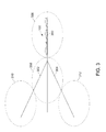
Figure 3 illustrates one of the rail vehicles shown inFigure 1 traveling along tracks that pass through several geographic zones in accordance with one embodiment; -
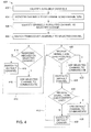
Figure 4 is a flowchart of a method for communicating with a rail vehicle in accordance with one embodiment; -
Figure 5 is a flowchart of a method for communicating with a rail vehicle in accordance with another embodiment; and -
Figure 6 is a flowchart of a method for communicating with a rail vehicle in accordance with another embodiment. -
Figure 1 is a schematic illustration ofdistributed power trains communication systems distributed power trains Figure 1 , therail vehicles units 108 coupled with several remote and/or trailing poweredunits cars 112. The trailing and remote powered units may be referred to as "remote powered units." The lead and remote poweredunits rail vehicles tracks units propulsion subsystems rail vehicles - In one embodiment, the lead powered
units 108 are leading locomotives disposed at the front end of therail vehicles units units 108 between the lead poweredunits 108 and the back ends of therail vehicles individual cars 112 may be storage units for carrying goods and/or passengers along thetracks - The remote powered
units units 108 in that the remote poweredunits unit 108. A remote poweredunit unit 108 by a significant distance in order for the remote poweredunit unit 108. For example, the remote poweredunit unit 108 and still be remote from the lead poweredunit 108. The number of lead and remote poweredunits rail vehicles Figure 1 . - The lead powered
unit 108 or the remote poweredunits units units unit unit 108 is organized intoconsist group 123, which may include the lead poweredunit 108 and one or more remote poweredunits 109 that are the same or similar models and/or are the same or similar type of power unit. The remote poweredunit 110 is organized intoconsist group 124, which may include the remote poweredunit 110 and one or more trail poweredunits 109 that are the same or similar models and/or are the same or similar type of power unit. For example, theconsist group units units 109 that are manufactured by the same entity, supply the same or similar tractive force, have the same or similar braking capacity, have the same or similar types of brakes, and the like. The lead and/or remote poweredunits units 109 in a consistgroup - The lead and remote powered
units rail vehicle units same rail vehicle rail vehicle units rail vehicles communication systems units same rail vehicle communication systems antennas 122 capable of wirelessly communicating data signals between the lead and remote poweredunits same rail vehicle communication systems units different rail vehicles - The data signals communicated among the
powered units rail vehicles rail vehicles units rail vehicle propulsion subsystems units same rail vehicle powered units unit 108 may transmit a data signal that instructs the remote poweredunits propulsion subsystem units powered units unit 108 to report on a status or state of thepropulsion subsystems units unit 108 to change a tractive and/or braking effort supplied by thepropulsion subsystem unit 108. - The
communication systems 106 and/or 126 may communicate data signals among each other over communication channels. A communication channel is associated with a signal parameter, such as a frequency or range of frequencies at which a signal is communicated on the channel. For example, thecommunication systems communication systems different units communication system - One or more of the
communication systems communication system communication system 106 of therail vehicle 100 to transmit and/or receive data signals (an "operational channel") is being used by manyother communication systems nearby rail vehicles communication system 106 of therail vehicle 100 may switch to another channel to transmit and/or receive the data signals (a "selected channel"). Thecommunication systems communication systems many communication systems other communication systems communication systems -
Figure 2 is a schematic diagram of thecommunication systems communication system 106 may be referred to as thelead communication system 106 as thecommunication system 106 is disposed in the lead poweredunit 108 in the embodiment shown inFigure 1 . Thecommunication system 126 may be referred to as theremote communication system 126 as thecommunication system 126 is disposed in one or more of the remote poweredunits Figure 1 . - The lead and
remote communication systems remote transceiver assemblies transceiver assemblies transceiver assemblies antennas 122. The number ofantennas 122 shown inFigure 2 is provided merely as an example. The number ofantennas 122 coupled with eachtransceiver assembly Figure 2 . Thetransceiver assemblies transceiver assemblies - As described above, the
communication systems propulsion subsystems units Figure 1 ) (LeadUnit Propulsion Subsystem 120 and RemoteUnit Propulsion Subsystem 130, respectively). Thelead transceiver assembly 200 receives data signals containing instructions from thepropulsion subsystems 120 and communicates the instructions to theremote transceiver assembly 202, which then transmits data signals containing instructions forpropulsion subsystems 130 to control the tractive and/or braking efforts provided by thepropulsion subsystems 130. - The lead and
remote communication systems remote selection modules remote monitoring modules monitoring modules monitoring modules remote unit memory memories - The
selection modules transceiver assemblies selection modules transceiver assemblies lead selection module 204 controls which channel thelead transceiver assembly 200 uses to transmit control signals to theremote transceiver assembly 202 and theremote selection module 206 controls which channel theremote transceiver assembly 202 uses to receive the data signals. - The
monitoring modules selection modules transceiver assemblies monitoring modules transceiver assemblies monitoring modules many rail vehicles Figure 1 ) and/orcommunication systems monitoring module rail vehicles communication systems rail vehicle communication system monitoring module other transceiver assemblies - Table 1 below illustrates how the population values for several channels may be calculated by the
monitoring modules transceiver assemblies rail vehicles Figure 1 ) arranged in different columns, with each column associated with a different channel. For example, thecommunication systems rail vehicles communication systems rail vehicles rail vehicles Figure 1 ) of therail vehicle rail vehicle units 108 may be unique so that few or no other lead poweredunits 108 have the same serial numbers (S/N).Table 1: Channel 1 Channel 2 Channel 3 Channel 4 Train A; S/N 1234 Train D; S/N 4567 Train F; S/N 6789 Train B; S/N 2345 Train E; S/N 5678 Train C; S/N 3456 - As shown in Table 1, three
rail vehicles rail vehicles rail vehicles rail vehicle monitoring modules rail vehicles communication systems rail vehicles Figure 1 ) using each channel, themonitoring modules communication systems rail vehicles - The
monitoring modules monitoring modules memory monitoring module rail vehicles communication systems units Figure 1 ) with data signals that are communicated over a channel. Themonitoring modules monitoring modules units 108 of therail vehicles Figure 1 ) that havecommunication systems - The
monitoring modules monitoring modules more rail vehicles Figure 1 ) switch channels, stop communicating over a channel, and/or begin communicating over a channel. Themonitoring modules monitoring modules transceiver assembly propulsion subsystems - For example, the
transceiver assemblies multiple antennas 122. InFigure 2 , theantennas 122 for eachtransceiver assembly antennas 122A transmit and/or receive data signals used to control operations of thepropulsion subsystems other antennas 122B scan or listen to one or more other channels to determine whichrail vehicles antennas 122A may cycle through the different Channels 1, 2, 3, and 4 to identify the serial numbers (S/N) of therail vehicles antennas 122B continue to transmit and receive data signals to control thepropulsion subsystem - As described above, load parameters are determined for the different channels. The monitoring or
selection modules - By way of example only, the load parameter for a channel may be based on a Quality of Service (QoS) index of the channel. The QoS index may be a measurement of the ability of the channel to transmit data signals at a predetermined transmission rate, data flow, throughput, or bandwidth. For example, the QoS index may be a comparison of the actual transmission rate of a channel with a predetermined threshold transmission rate of the channel. Alternatively, the QoS index may be a measurement of dropped packets of data signals that are transmitted through the channel, a delay or latency of the data signals, jitter or delays among the data packets in a data signal, an order of delivery of the various data packets in the data signal, and/or an error in transmitting one or more of the data packets.
- The load parameters for several channels are calculated by the
monitoring modules selection modules monitoring modules selection modules monitoring modules selection modules selection modules - The channel that is chosen by the
selection modules selection modules transceiver assemblies transceiver assemblies selection modules transceiver assemblies transceiver assemblies transceiver assembly selection modules transceiver assemblies - With respect to the example embodiment described in connection with Table 1 above, a rail vehicle that currently not communicating over any of the Channels 1, 2, 3, or 4 (such as a rail vehicle having a communication system that was recently activated or turned on) may have a
communication system transceiver assemblies units communication systems other rail vehicles Table 2: Channel 1 Channel 2 Channel 3 Channel 4 Train A; S/N 1234 Train D; S/N 4567 New Train; S/N 7891 Train F; S/N 6789 Train B; S/N 2345 Train E; S/N 5678 Train C; S/N 3456 - The rail vehicles may repeatedly update the table or listings that reflect the distribution of the rail vehicles among the different available channels. For example, the
communication systems communication systems - In the event that the
communication systems more rail vehicles rail vehicles communication systems communication systems respective transceiver assemblies many communication systems communication systems - The priority index may be a number or measurement of a priority of a
rail vehicle communication systems rail vehicle Figure 1 ) of therail vehicle rail vehicle communication systems rail vehicles - As described above, the
communication systems rail vehicles communication systems rail vehicles tracks Figure 1 ). Repeatedly or periodically updating the channel distributions and changing whichrail vehicles rail vehicles - In one embodiment, one or more the
transceiver assemblies rail vehicle Figure 1 ) that includes thetransceiver assembly antennas 122 of thetransceiver assembly rail vehicle transceiver assembly monitoring module monitoring module rail vehicle communication systems rail vehicle - With continued reference to
Figure 2 ,Figure 3 illustrates therail vehicle 100 traveling alongtracks geographic zones track 300 extends through thezones track 302 intersects thetrack 300 and extends through thezones track 304 intersects thetrack 300 and extends through thezones zones zones zones - The
zones rail vehicle 100 to use for communication. For example, each of thezones other zones zones zones adjacent zones - As described above, the
monitoring module rail vehicle 100 as therail vehicle 100 travels along one or more of thetracks different zones memories monitoring module zone rail vehicle 100 is approaching (the "approaching zone"). Themonitoring module monitoring modules rail vehicles communication systems - In the illustrated embodiment, Table 3 may represent the channel distribution for the
rail vehicles zone 306 in which therail vehicle 100 currently is travelling (the "current zone").Table 3: Current Zone: Channel 1 Current Zone: Channel 2 Current Zone: Channel 3 Current Zone: Channel 4 Train A; S/N 1234 Train D; S/N 4567 Train F; S/N 6789 Train B; S/N 2345 Train E; S/N 5678 Train C; S/N 3456 - Table 4 illustrates an example of population values for channels of an approaching zone that may be calculated by the
monitoring modules Table 4: Approaching Zone: Channel 1 Approaching Zone: Channel 2 Approaching Zone: Channel 3 Approaching Zone: Channel 4 Train G; S/N 0123 Train I; S/N 0345 Train L; S/N 0678 Train M; S/N 0789 Train H; S/N 0234 Train J; S/N 0456 Train N; S/N 0891 Train K; S/N 0567 - For example, Table 3 may represent the channel distribution for
zone 306 and Table 4 may represent the channel distribution forzone 308 as therail vehicle 100 moves through thecurrent zone 306 and toward the approachingzone 308. Therail vehicle 100 may be represented by Train F in Table 3. While thezones zones zone 306 may be different from the frequency or frequencies associated with Channel 1 inzone 308, the frequency or frequencies associated with Channel 2 inzone 306 may be different from the frequency or frequencies associated with Channel 2 inzone 308, the frequency or frequencies associated with Channel 3 inzone 306 may be different from the frequency or frequencies associated with Channel 3 inzone 308, and the frequency or frequencies associated with Channel 4 inzone 306 may be different from the frequency or frequencies associated with Channel 4 inzone 308. In one embodiment, thezones zone - Based on the channel distribution of the approaching
zone 308, theselection module transceiver assemblies zone 308 based on the load parameters of the channels in the approachingzone 308. Theselection module transceiver assemblies zone 308 when therail vehicle 100 enters the approachingzone 308 in one embodiment. For example, Train F may switch from using Channel 4 inzone 306 to Channel 3 inzone 308 when Train F enters thezone 308, just prior to Train F entering thezone 308, or after Train F has entered thezone 308. Therail vehicle 100 may switch to sparsely populated channels ofother zones rail vehicle 100 travels along one or more of thetracks rail vehicle 100 may switch between channels of thezone 308 as therail vehicle 100 travels through thezone 308 similar to as described above. -
Figure 4 is a flowchart of amethod 400 for communicating with a rail vehicle in accordance with one embodiment. Themethod 400 may be used in conjunction with one or more of thecommunication systems 106, 126 (shown inFigure 1 ) in order to communicate between different units of a rail vehicle, such as between lead poweredunits 108 and/or remote poweredunits 109, 110 (shown inFigure 1 ). In one embodiment, themethod 400 is used to select a channel forcommunication systems rail vehicle Figure 1 ) to use when thecommunication system method 400 may be used to initializecommunication systems communication systems method 400 may be used after thecommunication systems - At 402, the channels that are available for communicating data signals are identified. For example, a list, table, or database in the
memory 208 and/or 210 (shown inFigure 2 ) may indicate which channels are available for thecommunication system 106 and/or 126 (shown inFigure 1 ). The list of available channels may be based on the location of therail vehicle Figure 1 ). For example, the list of channels may be based on whichzone Figure 3 ) that therail vehicle Figure 1 ) having thecommunication systems - At 404, the available channels monitored to determine load parameters of the channels. For example, the
monitoring modules 212, 214 (shown inFigure 2 ) may calculate population values for the channels and/or other channel indices, as described above. - At 406, one or more sparsely populated channels are identified based on the load parameters. For example, the
selection modules 204, 206 (shown inFigure 2 ) may determine which channels have relatively low population values. A channel may be a sparsely populated channel if the channel has a lower population value than one or more other channels. As described above, the load parameters may be based on other channel indices, such as QoS indices. Theselection module - At 408, a transceiver assembly is switched to the selected channel. For example, the
transceiver assembly 200 and/or 202 (shown inFigure 2 ) may be activated and switched to the selected channel. Thetransceiver assemblies selection modules 204, 206 (shown inFigure 2 ). - Flow of the
method 400 proceeds along one of a plurality ofpaths method 400 to communicate. For example, if the lead communication system 106 (shown inFigure 1 ) of the lead powered unit 108 (shown inFigure 1 ) is employing themethod 400 to select a channel, then flow of themethod 400 may proceed along thepath 410 to 414. If the remote communication system 126 (shown inFigure 1 ) of the remotepowered unit 109, 110 (shown inFigure 1 ) or the non-powered unit 112 (shown inFigure 1 ) is using themethod 400 to select a channel, then flow of themethod 400 may proceed alongpath 412 to 420. - Along the
path 410 and at 414, the lead communication system 106 (shown inFigure 1 ) transmits a data signal on the selected channel and determines if thelead communication system 106 receives a responsive data signal on the selected channel. Thelead communication system 106 transmits the data signal to determine if the remote communication systems 126 (shown inFigure 1 ) of thesame rail vehicle Figure 1 ) are communicating on the selected channel. The data signal transmitted by thelead communication system 106 may include the serial number (S/N) or other unique identification of thelead communication system 106. The serial number (S/N) or other identification can be used by theremote communication systems 126 to verify that theremote communication systems 126 are communicating with thelead communication system 106 of thesame rail vehicle lead communication system 106 may transmit a plurality of the data signals on the selected channel and wait a predetermined period of time after sending each data signal in order to determine if the lead andremote communication systems - If the lead communication system 106 (shown in
Figure 1 ) does not receive a responsive data signal from the remote communication systems 126 (shown inFigure 1 ) on the selected channel, then this absence of the responsive data signal may indicate that the lead andremote communication systems method 400 proceeds to 416. Alternatively, if thelead communication system 106 does receive a responsive data signal from theremote communication systems 126 on the selected channel, then the receipt of the responsive data signal may indicate that the lead andremote communication systems method 400 proceeds to 418. - At 416, the lead communication system 106 (shown in
Figure 1 ) switches to a default channel. Thelead communication system 106 may be associated with a channel that thelead communication system 106 and the remote communication systems 126 (shown inFigure 1 ) switch to when the lead andremote communication systems lead communication system 106 is unable to communicate with theremote communication systems 126 on the selected channel, thelead communication system 106 switches to the default channel to communicate with theremote communication systems 126. - At 418, the lead communication system 106 (shown in
Figure 1 ) uses the selected communication channel to communicate with the remote communication systems 126 (shown inFigure 1 ). For example, as the lead andremote communication systems remote communication systems - Along the
path 412 and at 420, the remote communication system 126 (shown inFigure 1 ) determines if a data signal is received from the lead communication system 106 (shown inFigure 1 ) on the selected channel. For example, theremote communication systems 126 may determine if the data signal transmitted on the selected channel at 414 of thepath 410 is received by theremote communication systems 126. - If the remote communication system 126 (shown in
Figure 1 ) does receive a data signal from the lead communication system 106 (shown inFigure 1 ) on the selected channel, then the receipt of the data signal may indicate that the lead andremote communication systems method 400 proceeds to 422. Alternatively, if theremote communication system 126 does not receive a data signal from thelead communication system 106 on the selected channel, then this absence of the data signal may indicate that the lead andremote communication systems method 400 proceeds to 424. - At 422, the remote communication system 126 (shown in
Figure 1 ) communicates data signals with the lead powered unit 106 (shown inFigure 1 ) on the selected channel. For example, theremote communication system 126 may receive instructions that direct operation of the remote unit propulsion subsystems 130 (shown inFigure 1 ) and/or transmit data instructions providing feedback on the health or operations of the remote poweredunits 109, 110 (shown inFigure 1 ). - At 424, the remote communication system 126 (shown in
Figure 1 ) switches to a default channel. As described above, the lead andremote communication systems 106, 126 (shown inFigure 1 ) may be associated with a channel that thecommunication systems communication systems remote communication systems 126 switch to the default channel to attempt communication with thelead communication system 106 on the default channel. - At 426, a determination is made as to whether a data signal is received on the default channel. For example, the remote communication system 126 (shown in
Figure 1 ) may determine if a data signal is received from the lead communication system 106 (shown inFigure 1 ) on the default channel. If the data signal is received on the default channel, then receipt of the data signal indicates that the lead andremote communication systems method 400 proceeds to 428. Alternatively, if the data signal is not received on the default channel, then the failure to receive the data signal indicates that the lead andremote communication systems method 400 proceeds to 430. - At 428, the remote communication system 126 (shown in
Figure 1 ) communicates with the lead communication system 106 (shown inFigure 1 ) on the default channel. For example, theremote communication system 126 may receive instructions on the default channel that are implemented by theremote communication system 126 to control operation of the remote unit propulsion subsystem 130 (shown inFigure 1 ). - At 430, the remote communication system 126 (shown in
Figure 1 ) switches back to the selected channel to attempt communication with the lead communication system 106 (shown inFigure 1 ) again. For example, as communication on the default channel was unsuccessful, theremote communication system 126 may return to the selected channel and attempt to establish communications with thelead communication system 106 on the selected channel. Flow of themethod 400 then returns to 420, where another determination is made as to whether a data signal is received from thelead communication system 106 on the selected channel. Themethod 400 may continue in a loop-wise manner until communication is established with thelead communication system 106 on the default or selected channel. -
Figure 5 is a flowchart of amethod 500 for communicating with a rail vehicle in accordance with another embodiment. Themethod 500 may be used in conjunction with the lead and/orremote communication units 106, 126 (shown inFigure 1 ) to switch which channels are used to communicate between thecommunication units method 500 may be used by the lead and/orremote communication units communication units - At 502, data signals are communicated on an operating channel. For example, the lead and
remote communication units 106, 126 (shown inFigure 1 ) currently may be communicating data signals on the operating channel, such as to remotely control operations of the remote unit propulsion subsystems 130 (shown inFigure 1 ). - At 504, one or more channels monitored to determine load parameters of the channels. For example, the
monitoring modules 212, 214 (shown inFigure 2 ) may calculate population values for the channels and/or other channel indices, as described above. - At 506, one or more sparsely populated channels are identified based on the load parameters. For example, the
selection modules 204, 206 (shown inFigure 2 ) may determine which channels have relatively low population values. A channel may be a sparsely populated channel if the channel has a lower population value than one or more other channels. The load parameters may be based on other channel indices, such as QoS indices. Theselection module - At 508, priority indices are identified for the
rail vehicles Figure 1 ) that may switch to the selected channel. For example, afirst rail vehicle 100 may determine a priority index for itself and forother rail vehicles rail vehicles rail vehicles more rail vehicles rail vehicles Figure 1 ) of therail vehicles - At 510, a determination is made as to whether the priority index of a first rail vehicle 100 (shown in
Figure 1 ) permits therail vehicle 100 to switch to the selected channel. For example, the priority index of therail vehicle 100 may be compared to the priority indices ofother rail vehicles 102, 104 (shown inFigure 1 ) to determine if therail vehicle 100 can switch to the selected channel. As described above, if therail vehicle 100 has a sufficiently high priority, then thecommunication systems 106, 126 (shown inFigure 1 ) of therail vehicle 100 may switch to the selected channel. As a result, flow of themethod 500 proceeds to 512. On the other hand, if therail vehicle 100 has too low of a priority such thatother rail vehicles communication systems rail vehicle 100 may not switch to the selected channel. As a result, flow of themethod 500 proceeds to 514. The priority index of therail vehicle 100 may be compared to the priority indices of therail vehicles rail vehicle 100, then thecommunication systems rail vehicle 100 may not switch to the selected channel. As a result, flow of themethod 500 proceeds to 514. For example, the determination of whichrail vehicles rail vehicles - At 512, the
communication systems 106, 126 (shown inFigure 1 ) of therail vehicle Figure 1 ) switch to and use the selected communication channel to communicate with each other. As described above, the lead and remote poweredunits Figure 1 ) may use thecommunication systems propulsion subsystems 120, 130 (shown inFigure 1 ). - At 514, the
communication systems 106, 126 (shown inFigure 1 ) of therail vehicle Figure 1 ) remain on the operating channel that was being used. For example, thecommunication systems rail vehicle rail vehicle communication systems - Flow of the
method 500 may return to 504 from 512 and/or 514 where the load parameters of the channels are again examined to determine if thecommunication systems 106, 126 (shown inFigure 1 ) of arail vehicle Figure 1 ) may switch to a less populated channel. Themethod 500 can continue in a loop-wise manner to repeatedly monitor how heavily populated various channels are and potentially switch thecommunication systems -
Figure 6 is a flowchart of amethod 600 for communicating with a rail vehicle in accordance with another embodiment. Themethod 600 may be used by a rail vehicle 100 (shown inFigure 1 ) traveling between or acrossmultiple zones Figure 3 ) to switch between different channels among thezones zones - At 602, the rail vehicle 100 (shown in
Figure 1 ) communicates using a current operating channel. For example, thecommunication systems 106, 126 (shown inFigure 1 ) of therail vehicle 100 may communicate over an operating channel while therail vehicle 100 is in a first zone 306 (shown inFigure 3 ). - At 604, a determination is made as to whether the rail vehicle 100 (shown in
Figure 1 ) is approaching adifferent zone Figure 3 ) than thezone rail vehicle 100 currently is travelling. For example, therail vehicle 100 may use GPS or another manner for identifying whichzone rail vehicle 100 is approaching and/or a boundary between thecurrent zone rail vehicle 100 and azone rail vehicle 100 is approaching. If therail vehicle 100 is approaching adifferent zone method 600 proceeds to 606. Alternatively, if therail vehicle 100 is not approaching adifferent zone method 600 returns to 602. Themethod 600 may proceed in a loop-wise manner until therail vehicle 100 approaches adifferent zone - At 606, the channels of the approaching zone are identified. As described above, the
memory 208, 210 (shown inFigure 2 ) of thecommunication systems 106, 126 (shown inFigure 1 ) may maintain a database or list of the channels that are associated with the approaching zone. Alternatively, a tower having a transceiver assembly and located in or near the approaching zone may broadcast a wireless data signal that includes a listing of the channels of the approaching zone. - At 608, the channels in the approaching zone are monitored to determine load parameters of the channels. For example, the
monitoring modules 212, 214 (shown inFigure 2 ) may calculate population values for the channels and/or other channel indices of the channels associated with the approaching zone, as described above. - At 610, one or more sparsely populated channels of the approaching zone are identified based on the load parameters. For example, the
selection modules 204, 206 (shown inFigure 2 ) may determine which channels associated with the approaching channel have relatively low population values. A channel may be a sparsely populated channel if the channel has a lower population value than one or more other channels associated with the approaching zone. As described above, the load parameters may be based on other channel indices, such as QoS indices. Theselection module - At 612, the rail vehicle 100 (shown in
Figure 1 ) switches to a selected channel of the approachingzone Figure 3 ) when therail vehicle 100 enters the approachingzone communication systems 106, 126 (shown inFigure 1 ) of therail vehicle 100 may switch to the selected channel of the approachingzone rail vehicle 100 enters the approachingzone communication systems zone - In one embodiment, the
communication systems 106, 126 (shown inFigure 1 ) may switch to a selected channel of the approachingzone Figure 3 ) based on a priority index of the rail vehicle 100 (shown inFigure 1 ), as described above. - Flow of the
method 600 may return to 602, where the rail vehicle 100 (shown inFigure 1 ) communicates on the selected channel as the operating channel. Themethod 600 may continue in a loop-wise manner to determine when therail vehicle 100 approaches anotherzone Figure 3 ) and to identify and/or switch to a channel of thezones rail vehicle 100 passes through thezones - One or more embodiments described herein provide for the ability to switch communication channels used by a DP rail vehicle in order to permit powered units of the rail vehicle to communicate over channels that are not heavily populated, or channels that are less populated with other rail vehicles. The switching between an operational channel to a selected channel by the communication systems of the rail vehicle may be performed automatically or manually, such as by an operator moving or pressing a switch, button, or other actuator. For example, in accordance with one embodiment, an operator of a rail vehicle may be provided with a display device that visually presents a table or list of available channels and the associated load parameters of the channels. The operator may then manually select which channel the communication systems of the rail vehicle will use.
- It should be noted that although one or more embodiments may be described in connection with powered rail vehicle systems, the embodiments described herein are not limited to trains. In particular, one or more embodiments may be implemented in connection with different types of rail vehicles (e.g., a vehicle that travels on one or more rails, such as single locomotives and railcars, powered ore carts and other mining vehicles, light rail transit vehicles, and the like) and other vehicles. Moreover, in at least one embodiment, the terms lead powered unit and remote or trailing powered units are intended to encompass vehicles capable of self-propulsion other than locomotives. For example, while at least one embodiment describes the lead and remote or trailing powered units as being locomotives in a distributed power train, the lead and remote or trailing powered units are non-locomotive vehicles that are capable of self-propulsion in one or more other embodiments.
- Example embodiments of systems and methods for switching between communication channels used by powered units in a rail vehicle to communicate with each other are provided. At least one technical effect described herein includes a method and system that allows the powered units of the rail vehicle to switch from heavily populated communication channels to less populated communication channels.
- In one embodiment, a communication system for a rail vehicle includes: a transceiver assembly for selectively communicating a data signal (e.g., a "first" data signal) over a plurality of communication channels, the data signal related to distributed power operations of the rail vehicle; a selection module communicatively coupled with the transceiver assembly, the selection module capable of switching the transceiver assembly to any of the communication channels; and a monitoring module communicatively coupled with the selection module, the monitoring module configured to determine a load parameter of one or more of the communication channels, the load parameter based on a population value of the one or more communication channels, wherein the selection module switches the transceiver assembly to a selected channel of the communication channels based on the load parameter for communicating the data signal over the selected channel.
- In another aspect, the monitoring module determines the load parameter based on a number of transmitting vehicles communicating data signals (e.g., the first data signal and/or second data signals) on one or more of the communication channels (e.g., all the communication channels).
- In another aspect, the monitoring module determines the load parameter for each of a plurality of the communication channels based on a number of transmitting vehicles communicating data signals over each of the plurality of the communication channels.
- In another aspect, the transceiver assembly is configured to be communicatively coupled with a propulsion subsystem of the rail vehicle, the transceiver assembly receiving an instruction over the selected channel with the propulsion subsystem implementing the instruction to change a tractive effort or braking effort of the rail vehicle.
- In another aspect, the transceiver assembly is a lead transceiver assembly, the selection module is a lead selection module, and the monitoring module is a lead monitoring module each disposed on a lead powered unit of the rail vehicle, and further comprising a remote transceiver assembly, a remote selection module, and a remote monitoring module each disposed on a remote powered unit of the rail vehicle.
- In another aspect, the lead and remote transceiver assemblies communicate the data signal on the selected channel to coordinate a tractive effort or braking effort of the lead and remote propulsion units.
- In another aspect, the remote selection module switches the remote transceiver assembly between the selected channel and a default channel until the data signal is communicated between the lead and remote transceiver assemblies.
- In another aspect, the monitoring module determines the load parameter of the one or more communication channels when the transceiver assembly is communicating the data signal on an operating channel and the selection module switches the transceiver assembly from the operating channel to the selected channel based on a comparison of the load parameters of the operating channel and the selected channel.
- In another aspect, the selection module switches the transceiver assembly to the selected channel based on a priority index associated with the rail vehicle.
- In another aspect, the monitoring module determines the load parameter for a first set of the communication channels that are available in a current geographical zone in which the rail vehicle is traveling and for a different second set of the communication channels that are available in a different geographical zone.
- In another aspect, the selection module switches the transceiver assembly to the selected channel in the second set of the communication channels when the rail vehicle enters the different geographical zone.
- In another embodiment, a method for communicating with a rail vehicle includes: monitoring a population value of one or more communication channels used by a transceiver assembly of the rail vehicle to communicate a data signal related to distributed power operations of the rail vehicle; determining a load parameter of the one or more communication channels based on the population value; and switching the transceiver assembly to a selected channel of the communication channels based on the load parameter.
- In another aspect, the monitoring step includes identifying a number of transmitting vehicles that are communicating data signals over the one or more communication channels.
- In another aspect, the method further includes communicating the data signal on the selected channel to change a tractive effort or braking effort of the rail vehicle.
- In another aspect, the transceiver assembly is a lead transceiver assembly of a lead powered unit of the rail vehicle and the switching step includes switching the lead transceiver assembly and a remote transceiver assembly of a remote powered unit of the rail vehicle to the selected channel.
- In another aspect, the method further includes communicating the data signal on the selected channel to coordinate a tractive effort or braking effort of the lead and remote powered units.
- In another aspect, the switching step includes switching the remote transceiver assembly of the remote powered unit between the selected channel and a default channel until the data signal is communicated between the lead and remote transceiver assemblies.
- In another aspect, the switching step includes switching the transceiver assembly to the selected channel based on a priority index associated with the rail vehicle.
- In another aspect, the monitoring step includes monitoring the population value for a first set of the communication channels that are available in a current geographical zone in which the rail vehicle is traveling and for a different second set of the communication channels that are available in a different geographical zone.
- In another aspect, the switching step includes switching the transceiver assembly to the selected channel in the second set of the communication channels when the rail vehicle enters the different geographical zone.
- In another embodiment, a non-transitory computer readable storage medium for a rail vehicle having a transceiver assembly, a selection module, and a monitoring module is provided. The computer readable storage medium includes instructions to: direct the monitoring module to determine a load parameter of one or more communication channels over which the transceiver assembly communicates a data signal related to distributed power operations of the rail vehicle, the load parameter based on a population value of the one or more communication channels; and direct the selection module to switch the transceiver assembly to a selected channel of the communication channels based on the load parameter.
- In another aspect, the instructions direct the monitoring module to determine the load parameter based on a number of transmitting vehicles communicating data signals on the one or more communication channels.
- In another aspect, the instructions direct the monitoring module to determine the load parameter for each of a plurality of the communication channels based on a number of transmitting vehicles communicating data signals over each of the plurality of the communication channels.
- In another aspect, the instructions direct the transceiver assembly to receive an instruction over the selected channel and communicate the instruction to a propulsion subsystem of the rail vehicle to change a tractive effort or braking effort of the rail vehicle.
- In another aspect, the transceiver assembly is a lead transceiver assembly of a lead propulsion unit of the rail vehicle, and the instructions direct the transceiver assembly to communicate the data signal on the selected channel with a remote transceiver assembly of a remote propulsion unit of the rail vehicle to coordinate a tractive effort or braking effort of the lead and remote propulsion units.
- In another aspect, the instructions direct the selection module to switch the transceiver assembly between the selected channel and a default channel until the data signal is communicated with a different transceiver assembly.
- In another aspect, the instructions direct the monitoring module to determine the load parameter of the one or more communication channels when the transceiver assembly is communicating the data signal on an operating channel, and the instructions direct the selection module to switch the transceiver assembly from the operating channel to the selected channel based on a comparison of the load parameters of the operating channel and the selected channel.
- In another aspect, the instructions direct the selection module to switch the transceiver assembly to the selected channel based on a priority index associated with the rail vehicle.
- In another aspect, the instructions direct the monitoring module to determine the load parameter for a first set of the communication channels that are available in a current geographical zone in which the rail vehicle is traveling and for a different second set of the communication channels that are available in a different geographical zone.
- In another aspect, the instructions direct the selection module to switch the transceiver assembly to the selected channel in the second set of the communication channels when the rail vehicle enters the different geographical zone.
- In an embodiment, a communication system for a rail vehicle comprises a transceiver assembly for selectively communicating a data signal over a plurality of communication channels. "Selectively" communicating means selecting one of the communication channels for communication of the data signal over that channel, or selecting two or more of the channels for communication of the data signal over the two or more channels, with any of the channels being potential candidates for data signal communication.
- Another embodiment relates to a non-transitory computer readable storage medium for a rail vehicle having a transceiver assembly, a selection module, and a monitoring module. The computer readable storage medium comprising instructions to: direct the monitoring module to determine a load parameter of one or more communication channels over which the transceiver assembly communicates a data signal related to distributed power operations of the rail vehicle, the load parameter based on a population value of the one or more communication channels; and direct the selection module to switch the transceiver assembly to a selected channel of the communication channels based on the load parameter.
- In another embodiment of the non-transitory computer readable storage medium, the instructions direct the monitoring module to determine the load parameter based on a number of transmitting vehicles communicating data signals on the one or more communication channels. In another embodiment, the instructions direct the selection module to switch the transceiver assembly between the selected channel and a default channel until the data signal is communicated with a different transceiver assembly. In another embodiment, the instructions direct the selection module to switch the transceiver assembly to the selected channel based on a priority index associated with the rail vehicle. In another embodiment, the instructions direct the monitoring module to determine the load parameter for a first set of the communication channels that are available in a current geographical zone in which the rail vehicle is traveling and for a different second set of the communication channels that are available in a different geographical zone.
- It is to be understood that the above description is intended to be illustrative, and not restrictive. For example, the above-described embodiments (and/or aspects thereof) may be used in combination with each other. In addition, many modifications may be made to adapt a particular situation or material to the teachings of the disclosed subject matter without departing from its scope. While the dimensions and types of materials described herein are intended to define the parameters of the disclosed subject matter, they are by no means limiting and are exemplary embodiments. Many other embodiments will be apparent to those of skill in the art upon reviewing the above description. The scope of the subject matter described herein should, therefore, be determined with reference to the appended claims, along with the full scope of equivalents to which such claims are entitled. In the appended claims, the terms "including" and "in which" are used as the plain-English equivalents of the respective terms "comprising" and "wherein." Moreover, in the following claims, the terms "first," "second," and "third," etc. are used merely as labels, and are not intended to impose numerical requirements on their objects. Further, the limitations of the following claims are not written in means-plus-function format and are not intended to be interpreted based on 35 U.S.C. § 112, sixth paragraph, unless and until such claim limitations expressly use the phrase "means for" followed by a statement of function void of further structure.
- This written description uses examples to disclose several embodiments of the described subject matter, including the best mode, and also to enable any person of ordinary skill in the art to practice the embodiments disclosed herein, including making and using any devices or systems and performing any incorporated methods. The patentable scope of the subject matter is defmed by the claims, and may include other examples that occur to those of ordinary skill in the art. Such other examples are intended to be within the scope of the claims if they have structural elements that do not differ from the literal language of the claims, or if they include equivalent structural elements with insubstantial differences from the literal languages of the claims.
- The foregoing description of certain embodiments of the disclosed subject matter will be better understood when read in conjunction with the appended drawings. To the extent that the figures illustrate diagrams of the functional blocks of various embodiments, the functional blocks are not necessarily indicative of the division between hardware circuitry. Thus, for example, one or more of the functional blocks (for example, processors or memories) may be implemented in a single piece of hardware (for example, a general purpose signal processor, microcontroller, random access memory, hard disk, and the like). Similarly, the programs may be stand alone programs, may be incorporated as subroutines in an operating system, may be functions in an installed software package, and the like. The various embodiments are not limited to the arrangements and instrumentality shown in the drawings.
- As used herein, an element or step recited in the singular and proceeded with the word "a" or "an" should be understood as not excluding plural of said elements or steps, unless such exclusion is explicitly stated. Furthermore, references to "one embodiment" of the present invention are not intended to be interpreted as excluding the existence of additional embodiments that also incorporate the recited features. Moreover, embodiments "comprising," "including," or "having" an element or a plurality of elements having a particular property may include additional such elements not having that property unless explicitly stated to the contrary.
Various aspects and embodiments of the present invention are defined by the following numbered clauses: - 1. A communication system for a rail vehicle, the system comprising:
- a transceiver assembly for selectively communicating a data signal over a plurality of communication channels, the data signal related to distributed power operations of the rail vehicle;
- a selection module communicatively coupled with the transceiver assembly, the selection module capable of switching the transceiver assembly to any of the communication channels; and
- a monitoring module communicatively coupled with the selection module, the monitoring module configured to determine a load parameter of one or more of the communication channels, the load parameter based on a population value of the one or more communication channels, wherein the selection module switches the transceiver assembly to a selected channel of the communication channels based on the load parameter for communicating the data signal over the selected channel.
- 2. The communication system of clause 1, wherein the monitoring module determines the load parameter based on a number of transmitting vehicles communicating data signals on one or more of the communication channels.
- 3. The communication system of clause 1 or clause 2, wherein the transceiver assembly is configured to be communicatively coupled with a propulsion subsystem of the rail vehicle, the transceiver assembly receiving an instruction over the selected channel with the propulsion subsystem implementing the instruction to change a tractive effort or braking effort of the rail vehicle.
- 4. The communication system of any preceding clause, wherein the transceiver assembly is a lead transceiver assembly, the selection module is a lead selection module, and the monitoring module is a lead monitoring module each disposed on a lead powered unit of the rail vehicle, and further comprising a remote transceiver assembly, a remote selection module, and a remote monitoring module each disposed on a remote powered unit of the rail vehicle.
- 5. The communication system of any preceding clause, wherein the remote selection module switches the remote transceiver assembly between the selected channel and a default channel until the data signal is communicated between the lead and remote transceiver assemblies.
- 6. The communication system of any preceding clause, wherein the selection module switches the transceiver assembly to the selected channel based on a priority index associated with the rail vehicle.
- 7. The communication system of any preceding clause, wherein the monitoring module determines the load parameter for a first set of the communication channels that are available in a current geographical zone in which the rail vehicle is traveling and for a different second set of the communication channels that are available in a different geographical zone.
- 8. The communication system of any preceding clause, wherein the selection module switches the transceiver assembly to the selected channel in the second set of the communication channels when the rail vehicle enters the different geographical zone.
- 9. A method for communicating with a rail vehicle, the method comprising:
- monitoring a population value of one or more communication channels used by a transceiver assembly of the rail vehicle to communicate a data signal related to distributed power operations of the rail vehicle;
- determining a load parameter of the one or more communication channels based on the population value; and
- switching the transceiver assembly to a selected channel of the communication channels based on the load parameter.
- 10. The method of clause 9, wherein the monitoring step includes identifying a number of transmitting vehicles that are communicating data signals over the one or more communication channels.
- 11. The method of clause 9 or clause 10, wherein the transceiver assembly is a lead transceiver assembly of a lead powered unit of the rail vehicle and the switching step includes switching the lead transceiver assembly and a remote transceiver assembly of a remote powered unit of the rail vehicle to the selected channel.
- 12. The method of any of clauses 9 to 11, wherein the switching step includes switching the remote transceiver assembly of the remote powered unit between the selected channel and a default channel until the data signal is communicated between the lead and remote transceiver assemblies.
- 13. The method of any of clauses 9 to 12, wherein the switching step includes switching the transceiver assembly to the selected channel based on a priority index associated with the rail vehicle.
- 14. The method of any of clauses 9 to 13, wherein the monitoring step includes monitoring the population value for a first set of the communication channels that are available in a current geographical zone in which the rail vehicle is traveling and for a different second set of the communication channels that are available in a different geographical zone.
- 15. The method of any of clauses 9 to 14, wherein the switching step includes switching the transceiver assembly to the selected channel in the second set of the communication channels when the rail vehicle enters the different geographical zone.
- 16. A non-transitory computer readable storage medium for a rail vehicle having a transceiver assembly, a selection module, and a monitoring module, the computer readable storage medium comprising instructions to:
- direct the monitoring module to determine a load parameter of one or more communication channels over which the transceiver assembly communicates a data signal related to distributed power operations of the rail vehicle, the load parameter based on a population value of the one or more communication channels; and
- direct the selection module to switch the transceiver assembly to a selected channel of the communication channels based on the load parameter.
- 17. The computer readable storage medium of clause 16, wherein the instructions direct the monitoring module to determine the load parameter based on a number of transmitting vehicles communicating data signals on the one or more communication channels.
- 18. The computer readable storage medium of clause 16 or clause 17, wherein the instructions direct the selection module to switch the transceiver assembly between the selected channel and a default channel until the data signal is communicated with a different transceiver assembly.
- 19. The computer readable storage medium of any of clauses 16 to 18, wherein the instructions direct the selection module to switch the transceiver assembly to the selected channel based on a priority index associated with the rail vehicle.
- 20. The computer readable storage medium of any of clauses 16 to 19, wherein the instructions direct the monitoring module to determine the load parameter for a first set of the communication channels that are available in a current geographical zone in which the rail vehicle is traveling and for a different second set of the communication channels that are available in a different geographical zone.
Claims (15)
- A communication system for a rail vehicle, the system comprising:a transceiver assembly for selectively communicating a data signal over a plurality of communication channels, the data signal related to distributed power operations of the rail vehicle;a selection module communicatively coupled with the transceiver assembly, the selection module capable of switching the transceiver assembly to any of the communication channels; anda monitoring module communicatively coupled with the selection module, the monitoring module configured to determine a load parameter of one or more of the communication channels, the load parameter based on a population value of the one or more communication channels, wherein the selection module switches the transceiver assembly to a selected channel of the communication channels based on the load parameter for communicating the data signal over the selected channel.
- The communication system of claim 1, wherein the monitoring module determines the load parameter based on a number of transmitting vehicles communicating data signals on one or more of the communication channels.
- The communication system of claim 1 or claim 2, wherein the transceiver assembly is configured to be communicatively coupled with a propulsion subsystem of the rail vehicle, the transceiver assembly receiving an instruction over the selected channel with the propulsion subsystem implementing the instruction to change a tractive effort or braking effort of the rail vehicle.
- The communication system of any preceding claim, wherein the transceiver assembly is a lead transceiver assembly, the selection module is a lead selection module, and the monitoring module is a lead monitoring module each disposed on a lead powered unit of the rail vehicle, and further comprising a remote transceiver assembly, a remote selection module, and a remote monitoring module each disposed on a remote powered unit of the rail vehicle.
- The communication system of any preceding claim, wherein the remote selection module switches the remote transceiver assembly between the selected channel and a default channel until the data signal is communicated between the lead and remote transceiver assemblies.
- The communication system of any preceding claim, wherein the selection module switches the transceiver assembly to the selected channel based on a priority index associated with the rail vehicle.
- The communication system of any preceding claim, wherein the monitoring module determines the load parameter for a first set of the communication channels that are available in a current geographical zone in which the rail vehicle is traveling and for a different second set of the communication channels that are available in a different geographical zone.
- The communication system of any preceding claim, wherein the selection module switches the transceiver assembly to the selected channel in the second set of the communication channels when the rail vehicle enters the different geographical zone.
- A method for communicating with a rail vehicle, the method comprising:monitoring a population value of one or more communication channels used by a transceiver assembly of the rail vehicle to communicate a data signal related to distributed power operations of the rail vehicle;determining a load parameter of the one or more communication channels based on the population value; andswitching the transceiver assembly to a selected channel of the communication channels based on the load parameter.
- The method of claim 9, wherein the monitoring step includes identifying a number of transmitting vehicles that are communicating data signals over the one or more communication channels.
- The method of claim 9 or claim 10, wherein the transceiver assembly is a lead transceiver assembly of a lead powered unit of the rail vehicle and the switching step includes switching the lead transceiver assembly and a remote transceiver assembly of a remote powered unit of the rail vehicle to the selected channel.
- The method of any of claims 9 to 11, wherein the switching step includes switching the remote transceiver assembly of the remote powered unit between the selected channel and a default channel until the data signal is communicated between the lead and remote transceiver assemblies.
- The method of any of claims 9 to 12, wherein the switching step includes switching the transceiver assembly to the selected channel based on a priority index associated with the rail vehicle.
- The method of any of claims 9 to 13, wherein the monitoring step includes monitoring the population value for a first set of the communication channels that are available in a current geographical zone in which the rail vehicle is traveling and for a different second set of the communication channels that are available in a different geographical zone.
- The method of any of claims 9 to 14, wherein the switching step includes switching the transceiver assembly to the selected channel in the second set of the communication channels when the rail vehicle enters the different geographical zone.
Applications Claiming Priority (1)
| Application Number | Priority Date | Filing Date | Title |
|---|---|---|---|
| US12/903,328 US8914167B2 (en) | 2010-10-13 | 2010-10-13 | Communication system for a rail vehicle and method for communicating with a rail vehicle |
Publications (3)
| Publication Number | Publication Date |
|---|---|
| EP2441642A2 true EP2441642A2 (en) | 2012-04-18 |
| EP2441642A3 EP2441642A3 (en) | 2015-10-28 |
| EP2441642B1 EP2441642B1 (en) | 2018-12-12 |
Family
ID=45033695
Family Applications (1)
| Application Number | Title | Priority Date | Filing Date |
|---|---|---|---|
| EP11184544.2A Active EP2441642B1 (en) | 2010-10-13 | 2011-10-10 | Communication system for a rail vehicle and method for communicating with a rail vehicle |
Country Status (2)
| Country | Link |
|---|---|
| US (1) | US8914167B2 (en) |
| EP (1) | EP2441642B1 (en) |
Cited By (3)
| Publication number | Priority date | Publication date | Assignee | Title |
|---|---|---|---|---|
| CN104718774A (en) * | 2012-09-19 | 2015-06-17 | 富士通株式会社 | Wireless communication system, wireless communication device, and wireless communication method for wireless communication system |
| EP2792573A3 (en) * | 2013-04-15 | 2017-04-12 | Hitachi, Ltd. | Train control system |
| CN109153396A (en) * | 2016-05-12 | 2019-01-04 | 株式会社京三制作所 | On-board units and ground systems |
Families Citing this family (16)
| Publication number | Priority date | Publication date | Assignee | Title |
|---|---|---|---|---|
| US9199653B2 (en) * | 2010-10-13 | 2015-12-01 | General Electric Company | Communication system and method for communicating between vehicles of a vehicle consist |
| ES2671344T3 (en) * | 2010-12-09 | 2018-06-06 | Siemens S.A.S | Method for communicating information between an on-board control unit and a public transport network |
| US9026282B2 (en) | 2012-11-30 | 2015-05-05 | Electro-Motive Diesel, Inc. | Two-tiered hierarchically distributed locomotive control system |
| US8868267B2 (en) | 2012-11-30 | 2014-10-21 | Electro-Motive Diesel, Inc. | Remote update in locomotive distributed control systems |
| US8935020B2 (en) | 2012-11-30 | 2015-01-13 | Electro-Motive Diesel, Inc. | Back-up and redundancy of modules in locomotive distributed control systems |
| US8954210B2 (en) | 2012-11-30 | 2015-02-10 | Electro-Motive Diesel, Inc. | Distributed control system for a locomotive |
| JP6153882B2 (en) * | 2014-03-27 | 2017-06-28 | 日立建機株式会社 | Vehicle traveling system and operation management server |
| US9469317B2 (en) | 2014-06-03 | 2016-10-18 | Westinghouse Air Brake Technologies Corporation | Locomotive-to-wayside device communication system and method and wayside device therefor |
| US9227639B1 (en) | 2014-07-09 | 2016-01-05 | General Electric Company | System and method for decoupling a vehicle system |
| US9585056B2 (en) * | 2014-11-07 | 2017-02-28 | Motorola Solutions, Inc. | Method and apparatus for routing traffic within a communication system |
| CN105992256B (en) | 2015-03-03 | 2019-08-27 | 华为技术有限公司 | Channel management method, device and system for wireless local area network in rail transit |
| US10623216B1 (en) * | 2018-11-08 | 2020-04-14 | Ge Global Sourcing Llc | Vehicle communication system using incompatible modulation techniques |
| EP3726189B1 (en) * | 2019-04-16 | 2025-08-06 | ALSTOM Holdings | A method for determining loading data in connection with a load supported by a transportation vehicle |
| US12428043B2 (en) * | 2020-07-31 | 2025-09-30 | Westinghouse Air Brake Technologies Corporation | System and method for establishing vehicle distributed power arrangement |
| CN115009327B (en) * | 2022-05-25 | 2024-06-04 | 交控科技股份有限公司 | Train resource release method and device |
| CN118018988B (en) * | 2024-01-03 | 2025-02-18 | 中原大易科技有限公司 | Loading and unloading flow control method and system based on radio frequency identification and singlechip |
Family Cites Families (68)
| Publication number | Priority date | Publication date | Assignee | Title |
|---|---|---|---|---|
| US3706914A (en) * | 1972-01-03 | 1972-12-19 | George F Van Buren | Lighting control system |
| FR2409658A1 (en) * | 1977-11-22 | 1979-06-15 | Lampes Sa | ELECTRONICALLY CONTROLLED FEED RAIL |
| GB2074313B (en) * | 1980-03-25 | 1984-08-30 | Nissan Motor | Optical signal transmission systems |
| FR2513048A1 (en) * | 1981-09-16 | 1983-03-18 | Seinep Ste Electro Nord Est Pa | METHOD OF TELECOMMUNICATION BY AIRWAY AND DEVICE FOR IMPLEMENTING SAID METHOD |
| US4760797A (en) * | 1985-02-20 | 1988-08-02 | Southern Railway Company | Method and apparatus for automated tie detection and tamping |
| US4849651A (en) * | 1988-02-24 | 1989-07-18 | Hughes Aircraft Company | Two-state, bilateral, single-pole, double-throw, half-bridge power-switching apparatus and power supply means for such electronic power switching apparatus |
| JPH0759109B2 (en) * | 1988-04-20 | 1995-06-21 | 日本電気株式会社 | Car phone terminal with end call processing function |
| JPH0480140U (en) * | 1990-11-26 | 1992-07-13 | ||
| GB9104482D0 (en) * | 1991-03-04 | 1991-04-17 | Cooperheat Int Ltd | Solid state dc power supply |
| US5281859A (en) * | 1991-06-13 | 1994-01-25 | Molex Incorporated | Automatically switched power receptacle |
| US5833325A (en) | 1996-02-06 | 1998-11-10 | Westinghouse Air Brake Company | Freight brake control using train net braking ratio |
| US5785392A (en) | 1996-02-06 | 1998-07-28 | Westinghouse Air Brake Company | Selectable grade and uniform net shoe force braking for railway freight vehicle |
| US5820226A (en) | 1996-02-06 | 1998-10-13 | Westinghouse Air Brake Company | Freight brake control for uniform car deceleration |
| US5740547A (en) | 1996-02-20 | 1998-04-14 | Westinghouse Air Brake Company | Rail navigation system |
| US5986577A (en) | 1996-05-24 | 1999-11-16 | Westinghouse Air Brake Company | Method of determining car position |
| US5720455A (en) | 1996-11-13 | 1998-02-24 | Westinghouse Air Brake Company | Intra-train radio communication system |
| US5681015A (en) * | 1996-12-20 | 1997-10-28 | Westinghouse Air Brake Company | Radio-based electro-pneumatic control communications system |
| US5738311A (en) | 1997-02-13 | 1998-04-14 | Westinghouse Air Brake Company | Distributed power train separation detection |
| US5813635A (en) | 1997-02-13 | 1998-09-29 | Westinghouse Air Brake Company | Train separation detection |
| US5978718A (en) | 1997-07-22 | 1999-11-02 | Westinghouse Air Brake Company | Rail vision system |
| US5995881A (en) | 1997-07-22 | 1999-11-30 | Westinghouse Air Brake Company | Integrated cab signal rail navigation system |
| US5934764A (en) | 1997-08-05 | 1999-08-10 | Westinghouse Air Brake Company | Method for limiting brake cylinder pressure on locomotives equipped with distributive power and electronic brake systems |
| US5950967A (en) | 1997-08-15 | 1999-09-14 | Westinghouse Air Brake Company | Enhanced distributed power |
| US5969643A (en) | 1998-02-23 | 1999-10-19 | Westinghouse Air Brake Company | Method and apparatus for determining relative locomotive position in a train consist |
| US6275165B1 (en) | 1998-03-19 | 2001-08-14 | Westinghouse Air Brake Company | A.A.R. compliant electronic braking system |
| AU4189899A (en) | 1998-05-18 | 1999-12-06 | Westinghouse Air Brake Company | Serial data expansion unit |
| US6128558A (en) | 1998-06-09 | 2000-10-03 | Wabtec Railway Electronics, Inc. | Method and apparatus for using machine vision to detect relative locomotive position on parallel tracks |
| US6360998B1 (en) | 1998-06-09 | 2002-03-26 | Westinghouse Air Brake Company | Method and apparatus for controlling trains by determining a direction taken by a train through a railroad switch |
| US6377215B1 (en) | 1998-06-09 | 2002-04-23 | Wabtec Railway Electronics | Apparatus and method for detecting railroad locomotive turns by monitoring truck orientation |
| AU4690899A (en) * | 1998-06-18 | 2000-01-05 | Kline & Walker Llc | Automated devices to control equipment and machines with remote control and accountability worldwide |
| US5986579A (en) | 1998-07-31 | 1999-11-16 | Westinghouse Air Brake Company | Method and apparatus for determining railcar order in a train |
| US6216095B1 (en) | 1998-10-23 | 2001-04-10 | Westinghouse Air Brake Technologies Corporation | Automated in situ testing of railroad telemetry radios |
| US8135413B2 (en) * | 1998-11-24 | 2012-03-13 | Tracbeam Llc | Platform and applications for wireless location and other complex services |
| US6163089A (en) | 1998-12-31 | 2000-12-19 | Westinghouse Air Brake Technologies Corporation | Railway locomotive ECP train line control |
| US6898431B1 (en) * | 1999-05-24 | 2005-05-24 | Ericsson Inc. | Dynamic channel allocation in a sectored cell of a cellular communication system |
| US6322025B1 (en) | 1999-11-30 | 2001-11-27 | Wabtec Railway Electronics, Inc. | Dual-protocol locomotive control system and method |
| US6137274A (en) * | 2000-02-02 | 2000-10-24 | National Semiconductor Corporation | Switching DC-to-DC converter and conversion method with current sharing between paralleled channels |
| US6782044B1 (en) | 2000-02-07 | 2004-08-24 | Wabtec Corporation | Radio interference detection and screening system for locomotive control unit radios |
| CA2335419A1 (en) | 2000-03-03 | 2001-09-03 | Robert C. Kull | Railway locomotive brake controller |
| US6396252B1 (en) * | 2000-12-14 | 2002-05-28 | National Semiconductor Corporation | Switching DC-to-DC converter with discontinuous pulse skipping and continuous operating modes without external sense resistor |
| EP1393082B1 (en) * | 2001-05-10 | 2007-05-30 | Continental Teves AG & Co. oHG | Wheel speed sensor arrangement with transmission of additional information |
| US6862502B2 (en) | 2002-05-15 | 2005-03-01 | General Electric Company | Intelligent communications, command, and control system for a land-based vehicle |
| US6819011B2 (en) * | 2002-11-14 | 2004-11-16 | Fyre Storm, Inc. | Switching power converter controller with watchdog timer |
| US6850045B2 (en) * | 2003-04-29 | 2005-02-01 | Texas Instruments Incorporated | Multi-phase and multi-module power system with a current share bus |
| JP2005019801A (en) | 2003-06-27 | 2005-01-20 | Sony Corp | Steam oxidation method |
| US20050121971A1 (en) | 2003-12-05 | 2005-06-09 | Ring Michael E. | Serial train communication system |
| GB0328202D0 (en) | 2003-12-05 | 2004-01-07 | Westinghouse Brake & Signal | Railway vehicle detection |
| US7466116B2 (en) * | 2004-04-12 | 2008-12-16 | Renesas Technology America, Inc. | Current sensing circuit for a multi-phase DC-DC converter |
| US7385372B2 (en) * | 2004-05-27 | 2008-06-10 | Siemens Energy & Automation, Inc. | Auxiliary bus system |
| US7416262B2 (en) | 2004-06-09 | 2008-08-26 | Wabtec Holding Corp. | Brake system with integrated car load compensating arrangement |
| US7053593B2 (en) * | 2004-06-14 | 2006-05-30 | Hewlett-Packard Development Company, L.P. | Protection circuits for a DC-to-DC converter |
| KR100604546B1 (en) * | 2005-01-04 | 2006-07-24 | 주식회사 팬택앤큐리텔 | Hybrid terminal and channel acquisition method used therein |
| IL166804A (en) * | 2005-02-10 | 2012-08-30 | Cellvine Ltd | Apparatus and method for traffic load balancing in wireless networks |
| US7304567B2 (en) * | 2005-02-18 | 2007-12-04 | Nth Solutions, Llc | Method and apparatus for communicating control and other information over a power bus |
| JPWO2006101135A1 (en) * | 2005-03-22 | 2008-09-04 | 沖パワーテック株式会社 | Switching power supply circuit |
| JP4786742B2 (en) * | 2006-03-30 | 2011-10-05 | フィンメカニカ・ソシエタ・ペル・アツィオーニ | System for extending two-way satellite radio communication in tunnels |
| US7395141B1 (en) * | 2007-09-12 | 2008-07-01 | General Electric Company | Distributed train control |
| US7944978B2 (en) * | 2007-10-29 | 2011-05-17 | Lightwaves Systems, Inc. | High bandwidth data transport system |
| US7816985B2 (en) * | 2007-11-15 | 2010-10-19 | Intersil Americas Inc. | Switching amplifiers |
| CA2725065A1 (en) * | 2008-05-20 | 2009-11-26 | Live Meters, Inc. | Remote monitoring and control system comprising mesh and time synchronization technology |
| US20100142445A1 (en) * | 2008-09-04 | 2010-06-10 | Ludger Schlicht | Environments for a mobile, broadband, routable internet |
| US8310979B2 (en) * | 2008-09-21 | 2012-11-13 | General Electric Company | Message repeater and method of operation |
| US8159204B2 (en) * | 2008-09-29 | 2012-04-17 | Active-Semi, Inc. | Regulating current output from a buck converter without external current sensing |
| WO2010039680A1 (en) | 2008-10-01 | 2010-04-08 | Wabtec Holding Corp. | Method for transitioning from wide band to narrow band radios |
| US8148958B2 (en) * | 2008-12-19 | 2012-04-03 | Infineon Technologies Austria Ag | System and method for transmitting current sharing information among paralleled power trains |
| US8428798B2 (en) | 2010-01-08 | 2013-04-23 | Wabtec Holding Corp. | Short headway communications based train control system |
| EP2674957B1 (en) * | 2010-04-30 | 2017-02-15 | Rockwell Automation Germany GmbH & Co. KG | Single-channel safety output |
| JP5704953B2 (en) * | 2011-02-17 | 2015-04-22 | 三菱電機株式会社 | Satellite communication vehicle station |
-
2010
- 2010-10-13 US US12/903,328 patent/US8914167B2/en active Active
-
2011
- 2011-10-10 EP EP11184544.2A patent/EP2441642B1/en active Active
Non-Patent Citations (1)
| Title |
|---|
| None |
Cited By (3)
| Publication number | Priority date | Publication date | Assignee | Title |
|---|---|---|---|---|
| CN104718774A (en) * | 2012-09-19 | 2015-06-17 | 富士通株式会社 | Wireless communication system, wireless communication device, and wireless communication method for wireless communication system |
| EP2792573A3 (en) * | 2013-04-15 | 2017-04-12 | Hitachi, Ltd. | Train control system |
| CN109153396A (en) * | 2016-05-12 | 2019-01-04 | 株式会社京三制作所 | On-board units and ground systems |
Also Published As
| Publication number | Publication date |
|---|---|
| EP2441642B1 (en) | 2018-12-12 |
| US8914167B2 (en) | 2014-12-16 |
| US20120095626A1 (en) | 2012-04-19 |
| EP2441642A3 (en) | 2015-10-28 |
Similar Documents
| Publication | Publication Date | Title |
|---|---|---|
| EP2441642B1 (en) | Communication system for a rail vehicle and method for communicating with a rail vehicle | |
| US8428798B2 (en) | Short headway communications based train control system | |
| CN110239596B (en) | A mobile block train control method and system based on CTCS-3 | |
| CN110126882B (en) | Train control method and system and calculation method of movement authorization | |
| US8494695B2 (en) | Communications system and method for a rail vehicle | |
| KR102915800B1 (en) | Wireless Train Management System | |
| US7731129B2 (en) | Methods and systems for variable rate communication timeout | |
| AU2015296862B2 (en) | Method and system for communicating data with vehicles | |
| CN110126883B (en) | Planning method and on-board controller for train travel path | |
| US20140361126A1 (en) | Systems and method for controlling warnings at vehicle crossings | |
| CN102233887A (en) | CTCS (China train control system)-3 train operation control system | |
| KR101784393B1 (en) | System and method for controlling train | |
| CN105101094A (en) | Train operation control system | |
| KR101351507B1 (en) | Method for controlling operation of cbtc mode multi-formation train | |
| US9199653B2 (en) | Communication system and method for communicating between vehicles of a vehicle consist | |
| US20090212168A1 (en) | System and Method for Transporting Wayside Data on a Rail Vehicle | |
| CN106114561A (en) | The wireless communication network system framework of CBTC | |
| JP7324291B2 (en) | Radio controller and radio control system | |
| Schutte | Recent trends in automatic train controls | |
| KR101145645B1 (en) | A method to transmit the state information of vehicles and infrastructures for personal rapid transit system | |
| US20260021835A1 (en) | Systems and methods to extend dead reckoning using wayside equipment | |
| Igarashi et al. | Automatic train control system for the Shinkansen utilizing digital train radio | |
| CN115973234A (en) | Method, device and system for realizing multiple functions of novel transponder system | |
| CN117533377A (en) | Train control system, method, equipment and system for communication of occupancy identification and trackside equipment | |
| CN117104303A (en) | New transponders and induction loops realize multi-functional and scene application methods and systems |
Legal Events
| Date | Code | Title | Description |
|---|---|---|---|
| PUAI | Public reference made under article 153(3) epc to a published international application that has entered the european phase |
Free format text: ORIGINAL CODE: 0009012 |
|
| AK | Designated contracting states |
Kind code of ref document: A2 Designated state(s): AL AT BE BG CH CY CZ DE DK EE ES FI FR GB GR HR HU IE IS IT LI LT LU LV MC MK MT NL NO PL PT RO RS SE SI SK SM TR |
|
| AX | Request for extension of the european patent |
Extension state: BA ME |
|
| PUAL | Search report despatched |
Free format text: ORIGINAL CODE: 0009013 |
|
| AK | Designated contracting states |
Kind code of ref document: A3 Designated state(s): AL AT BE BG CH CY CZ DE DK EE ES FI FR GB GR HR HU IE IS IT LI LT LU LV MC MK MT NL NO PL PT RO RS SE SI SK SM TR |
|
| AX | Request for extension of the european patent |
Extension state: BA ME |
|
| RIC1 | Information provided on ipc code assigned before grant |
Ipc: B61L 15/00 20060101AFI20150918BHEP |
|
| 17P | Request for examination filed |
Effective date: 20160428 |
|
| RBV | Designated contracting states (corrected) |
Designated state(s): AL AT BE BG CH CY CZ DE DK EE ES FI FR GB GR HR HU IE IS IT LI LT LU LV MC MK MT NL NO PL PT RO RS SE SI SK SM TR |
|
| STAA | Information on the status of an ep patent application or granted ep patent |
Free format text: STATUS: EXAMINATION IS IN PROGRESS |
|
| 17Q | First examination report despatched |
Effective date: 20170403 |
|
| GRAP | Despatch of communication of intention to grant a patent |
Free format text: ORIGINAL CODE: EPIDOSNIGR1 |
|
| STAA | Information on the status of an ep patent application or granted ep patent |
Free format text: STATUS: GRANT OF PATENT IS INTENDED |
|
| INTG | Intention to grant announced |
Effective date: 20180620 |
|
| GRAS | Grant fee paid |
Free format text: ORIGINAL CODE: EPIDOSNIGR3 |
|
| GRAA | (expected) grant |
Free format text: ORIGINAL CODE: 0009210 |
|
| STAA | Information on the status of an ep patent application or granted ep patent |
Free format text: STATUS: THE PATENT HAS BEEN GRANTED |
|
| AK | Designated contracting states |
Kind code of ref document: B1 Designated state(s): AL AT BE BG CH CY CZ DE DK EE ES FI FR GB GR HR HU IE IS IT LI LT LU LV MC MK MT NL NO PL PT RO RS SE SI SK SM TR |
|
| REG | Reference to a national code |
Ref country code: GB Ref legal event code: FG4D |
|
| REG | Reference to a national code |
Ref country code: CH Ref legal event code: EP |
|
| REG | Reference to a national code |
Ref country code: AT Ref legal event code: REF Ref document number: 1075561 Country of ref document: AT Kind code of ref document: T Effective date: 20181215 |
|
| REG | Reference to a national code |
Ref country code: DE Ref legal event code: R096 Ref document number: 602011054709 Country of ref document: DE |
|
| REG | Reference to a national code |
Ref country code: IE Ref legal event code: FG4D |
|
| REG | Reference to a national code |
Ref country code: NL Ref legal event code: MP Effective date: 20181212 |
|
| REG | Reference to a national code |
Ref country code: LT Ref legal event code: MG4D |
|
| PG25 | Lapsed in a contracting state [announced via postgrant information from national office to epo] |
Ref country code: BG Free format text: LAPSE BECAUSE OF FAILURE TO SUBMIT A TRANSLATION OF THE DESCRIPTION OR TO PAY THE FEE WITHIN THE PRESCRIBED TIME-LIMIT Effective date: 20190312 Ref country code: NO Free format text: LAPSE BECAUSE OF FAILURE TO SUBMIT A TRANSLATION OF THE DESCRIPTION OR TO PAY THE FEE WITHIN THE PRESCRIBED TIME-LIMIT Effective date: 20190312 Ref country code: HR Free format text: LAPSE BECAUSE OF FAILURE TO SUBMIT A TRANSLATION OF THE DESCRIPTION OR TO PAY THE FEE WITHIN THE PRESCRIBED TIME-LIMIT Effective date: 20181212 Ref country code: LV Free format text: LAPSE BECAUSE OF FAILURE TO SUBMIT A TRANSLATION OF THE DESCRIPTION OR TO PAY THE FEE WITHIN THE PRESCRIBED TIME-LIMIT Effective date: 20181212 Ref country code: FI Free format text: LAPSE BECAUSE OF FAILURE TO SUBMIT A TRANSLATION OF THE DESCRIPTION OR TO PAY THE FEE WITHIN THE PRESCRIBED TIME-LIMIT Effective date: 20181212 Ref country code: ES Free format text: LAPSE BECAUSE OF FAILURE TO SUBMIT A TRANSLATION OF THE DESCRIPTION OR TO PAY THE FEE WITHIN THE PRESCRIBED TIME-LIMIT Effective date: 20181212 Ref country code: LT Free format text: LAPSE BECAUSE OF FAILURE TO SUBMIT A TRANSLATION OF THE DESCRIPTION OR TO PAY THE FEE WITHIN THE PRESCRIBED TIME-LIMIT Effective date: 20181212 |
|
| REG | Reference to a national code |
Ref country code: AT Ref legal event code: MK05 Ref document number: 1075561 Country of ref document: AT Kind code of ref document: T Effective date: 20181212 |
|
| PG25 | Lapsed in a contracting state [announced via postgrant information from national office to epo] |
Ref country code: GR Free format text: LAPSE BECAUSE OF FAILURE TO SUBMIT A TRANSLATION OF THE DESCRIPTION OR TO PAY THE FEE WITHIN THE PRESCRIBED TIME-LIMIT Effective date: 20190313 Ref country code: SE Free format text: LAPSE BECAUSE OF FAILURE TO SUBMIT A TRANSLATION OF THE DESCRIPTION OR TO PAY THE FEE WITHIN THE PRESCRIBED TIME-LIMIT Effective date: 20181212 Ref country code: RS Free format text: LAPSE BECAUSE OF FAILURE TO SUBMIT A TRANSLATION OF THE DESCRIPTION OR TO PAY THE FEE WITHIN THE PRESCRIBED TIME-LIMIT Effective date: 20181212 Ref country code: AL Free format text: LAPSE BECAUSE OF FAILURE TO SUBMIT A TRANSLATION OF THE DESCRIPTION OR TO PAY THE FEE WITHIN THE PRESCRIBED TIME-LIMIT Effective date: 20181212 |
|
| PG25 | Lapsed in a contracting state [announced via postgrant information from national office to epo] |
Ref country code: NL Free format text: LAPSE BECAUSE OF FAILURE TO SUBMIT A TRANSLATION OF THE DESCRIPTION OR TO PAY THE FEE WITHIN THE PRESCRIBED TIME-LIMIT Effective date: 20181212 |
|
| PG25 | Lapsed in a contracting state [announced via postgrant information from national office to epo] |
Ref country code: PL Free format text: LAPSE BECAUSE OF FAILURE TO SUBMIT A TRANSLATION OF THE DESCRIPTION OR TO PAY THE FEE WITHIN THE PRESCRIBED TIME-LIMIT Effective date: 20181212 Ref country code: CZ Free format text: LAPSE BECAUSE OF FAILURE TO SUBMIT A TRANSLATION OF THE DESCRIPTION OR TO PAY THE FEE WITHIN THE PRESCRIBED TIME-LIMIT Effective date: 20181212 Ref country code: PT Free format text: LAPSE BECAUSE OF FAILURE TO SUBMIT A TRANSLATION OF THE DESCRIPTION OR TO PAY THE FEE WITHIN THE PRESCRIBED TIME-LIMIT Effective date: 20190412 Ref country code: IT Free format text: LAPSE BECAUSE OF FAILURE TO SUBMIT A TRANSLATION OF THE DESCRIPTION OR TO PAY THE FEE WITHIN THE PRESCRIBED TIME-LIMIT Effective date: 20181212 |
|
| REG | Reference to a national code |
Ref country code: DE Ref legal event code: R081 Ref document number: 602011054709 Country of ref document: DE Owner name: TRANSPORTATION IP HOLDINGS, LLC (N.D.GES.D. ST, US Free format text: FORMER OWNER: GENERAL ELECTRIC COMPANY, SCHENECTADY, NY, US Ref country code: DE Ref legal event code: R081 Ref document number: 602011054709 Country of ref document: DE Owner name: GE GLOBAL SOURCING LLC, NORWALK, US Free format text: FORMER OWNER: GENERAL ELECTRIC COMPANY, SCHENECTADY, N.Y., US Ref country code: DE Ref legal event code: R081 Ref document number: 602011054709 Country of ref document: DE Owner name: GE GLOBAL SOURCING LLC, NORWALK, US Free format text: FORMER OWNER: GENERAL ELECTRIC COMPANY, SCHENECTADY, NY, US |
|
| RAP2 | Party data changed (patent owner data changed or rights of a patent transferred) |
Owner name: GE GLOBAL SOURCING LLC |
|
| PG25 | Lapsed in a contracting state [announced via postgrant information from national office to epo] |
Ref country code: IS Free format text: LAPSE BECAUSE OF FAILURE TO SUBMIT A TRANSLATION OF THE DESCRIPTION OR TO PAY THE FEE WITHIN THE PRESCRIBED TIME-LIMIT Effective date: 20190412 Ref country code: SK Free format text: LAPSE BECAUSE OF FAILURE TO SUBMIT A TRANSLATION OF THE DESCRIPTION OR TO PAY THE FEE WITHIN THE PRESCRIBED TIME-LIMIT Effective date: 20181212 Ref country code: SM Free format text: LAPSE BECAUSE OF FAILURE TO SUBMIT A TRANSLATION OF THE DESCRIPTION OR TO PAY THE FEE WITHIN THE PRESCRIBED TIME-LIMIT Effective date: 20181212 Ref country code: EE Free format text: LAPSE BECAUSE OF FAILURE TO SUBMIT A TRANSLATION OF THE DESCRIPTION OR TO PAY THE FEE WITHIN THE PRESCRIBED TIME-LIMIT Effective date: 20181212 Ref country code: RO Free format text: LAPSE BECAUSE OF FAILURE TO SUBMIT A TRANSLATION OF THE DESCRIPTION OR TO PAY THE FEE WITHIN THE PRESCRIBED TIME-LIMIT Effective date: 20181212 |
|
| REG | Reference to a national code |
Ref country code: DE Ref legal event code: R097 Ref document number: 602011054709 Country of ref document: DE |
|
| PLBE | No opposition filed within time limit |
Free format text: ORIGINAL CODE: 0009261 |
|
| STAA | Information on the status of an ep patent application or granted ep patent |
Free format text: STATUS: NO OPPOSITION FILED WITHIN TIME LIMIT |
|
| PG25 | Lapsed in a contracting state [announced via postgrant information from national office to epo] |
Ref country code: DK Free format text: LAPSE BECAUSE OF FAILURE TO SUBMIT A TRANSLATION OF THE DESCRIPTION OR TO PAY THE FEE WITHIN THE PRESCRIBED TIME-LIMIT Effective date: 20181212 Ref country code: SI Free format text: LAPSE BECAUSE OF FAILURE TO SUBMIT A TRANSLATION OF THE DESCRIPTION OR TO PAY THE FEE WITHIN THE PRESCRIBED TIME-LIMIT Effective date: 20181212 Ref country code: AT Free format text: LAPSE BECAUSE OF FAILURE TO SUBMIT A TRANSLATION OF THE DESCRIPTION OR TO PAY THE FEE WITHIN THE PRESCRIBED TIME-LIMIT Effective date: 20181212 |
|
| 26N | No opposition filed |
Effective date: 20190913 |
|
| PG25 | Lapsed in a contracting state [announced via postgrant information from national office to epo] |
Ref country code: TR Free format text: LAPSE BECAUSE OF FAILURE TO SUBMIT A TRANSLATION OF THE DESCRIPTION OR TO PAY THE FEE WITHIN THE PRESCRIBED TIME-LIMIT Effective date: 20181212 |
|
| PG25 | Lapsed in a contracting state [announced via postgrant information from national office to epo] |
Ref country code: MC Free format text: LAPSE BECAUSE OF FAILURE TO SUBMIT A TRANSLATION OF THE DESCRIPTION OR TO PAY THE FEE WITHIN THE PRESCRIBED TIME-LIMIT Effective date: 20181212 |
|
| REG | Reference to a national code |
Ref country code: CH Ref legal event code: PL |
|
| PG25 | Lapsed in a contracting state [announced via postgrant information from national office to epo] |
Ref country code: LI Free format text: LAPSE BECAUSE OF NON-PAYMENT OF DUE FEES Effective date: 20191031 Ref country code: CH Free format text: LAPSE BECAUSE OF NON-PAYMENT OF DUE FEES Effective date: 20191031 Ref country code: LU Free format text: LAPSE BECAUSE OF NON-PAYMENT OF DUE FEES Effective date: 20191010 |
|
| REG | Reference to a national code |
Ref country code: BE Ref legal event code: MM Effective date: 20191031 |
|
| PG25 | Lapsed in a contracting state [announced via postgrant information from national office to epo] |
Ref country code: BE Free format text: LAPSE BECAUSE OF NON-PAYMENT OF DUE FEES Effective date: 20191031 |
|
| GBPC | Gb: european patent ceased through non-payment of renewal fee |
Effective date: 20191010 |
|
| PG25 | Lapsed in a contracting state [announced via postgrant information from national office to epo] |
Ref country code: GB Free format text: LAPSE BECAUSE OF NON-PAYMENT OF DUE FEES Effective date: 20191010 Ref country code: FR Free format text: LAPSE BECAUSE OF NON-PAYMENT OF DUE FEES Effective date: 20191031 Ref country code: IE Free format text: LAPSE BECAUSE OF NON-PAYMENT OF DUE FEES Effective date: 20191010 |
|
| PG25 | Lapsed in a contracting state [announced via postgrant information from national office to epo] |
Ref country code: CY Free format text: LAPSE BECAUSE OF FAILURE TO SUBMIT A TRANSLATION OF THE DESCRIPTION OR TO PAY THE FEE WITHIN THE PRESCRIBED TIME-LIMIT Effective date: 20181212 |
|
| PG25 | Lapsed in a contracting state [announced via postgrant information from national office to epo] |
Ref country code: HU Free format text: LAPSE BECAUSE OF FAILURE TO SUBMIT A TRANSLATION OF THE DESCRIPTION OR TO PAY THE FEE WITHIN THE PRESCRIBED TIME-LIMIT; INVALID AB INITIO Effective date: 20111010 Ref country code: MT Free format text: LAPSE BECAUSE OF FAILURE TO SUBMIT A TRANSLATION OF THE DESCRIPTION OR TO PAY THE FEE WITHIN THE PRESCRIBED TIME-LIMIT Effective date: 20181212 |
|
| PG25 | Lapsed in a contracting state [announced via postgrant information from national office to epo] |
Ref country code: MK Free format text: LAPSE BECAUSE OF FAILURE TO SUBMIT A TRANSLATION OF THE DESCRIPTION OR TO PAY THE FEE WITHIN THE PRESCRIBED TIME-LIMIT Effective date: 20181212 |
|
| REG | Reference to a national code |
Ref country code: DE Ref legal event code: R081 Ref document number: 602011054709 Country of ref document: DE Owner name: TRANSPORTATION IP HOLDINGS, LLC (N.D.GES.D. ST, US Free format text: FORMER OWNER: GE GLOBAL SOURCING LLC, NORWALK, CT, US |
|
| P01 | Opt-out of the competence of the unified patent court (upc) registered |
Effective date: 20230530 |
|
| PGFP | Annual fee paid to national office [announced via postgrant information from national office to epo] |
Ref country code: DE Payment date: 20250919 Year of fee payment: 15 |