EP2441578A2 - Vehicle interior part - Google Patents
Vehicle interior part Download PDFInfo
- Publication number
- EP2441578A2 EP2441578A2 EP11173045A EP11173045A EP2441578A2 EP 2441578 A2 EP2441578 A2 EP 2441578A2 EP 11173045 A EP11173045 A EP 11173045A EP 11173045 A EP11173045 A EP 11173045A EP 2441578 A2 EP2441578 A2 EP 2441578A2
- Authority
- EP
- European Patent Office
- Prior art keywords
- base member
- resin material
- foamed resin
- cover member
- surface cover
- Prior art date
- Legal status (The legal status is an assumption and is not a legal conclusion. Google has not performed a legal analysis and makes no representation as to the accuracy of the status listed.)
- Withdrawn
Links
- 239000000463 material Substances 0.000 claims abstract description 71
- 239000011347 resin Substances 0.000 claims abstract description 67
- 229920005989 resin Polymers 0.000 claims abstract description 67
- 238000004519 manufacturing process Methods 0.000 claims description 30
- 238000000034 method Methods 0.000 claims description 12
- 238000005187 foaming Methods 0.000 claims description 6
- 229920002635 polyurethane Polymers 0.000 description 4
- 239000004814 polyurethane Substances 0.000 description 4
- 230000000694 effects Effects 0.000 description 3
- 239000012948 isocyanate Substances 0.000 description 2
- 150000002513 isocyanates Chemical class 0.000 description 2
- 229920005862 polyol Polymers 0.000 description 2
- 150000003077 polyols Chemical class 0.000 description 2
- 239000002994 raw material Substances 0.000 description 2
- 239000000853 adhesive Substances 0.000 description 1
- 230000001070 adhesive effect Effects 0.000 description 1
- 238000010438 heat treatment Methods 0.000 description 1
- 238000012986 modification Methods 0.000 description 1
- 230000004048 modification Effects 0.000 description 1
- 230000002093 peripheral effect Effects 0.000 description 1
- 238000007493 shaping process Methods 0.000 description 1
Images


Classifications
-
- B—PERFORMING OPERATIONS; TRANSPORTING
- B60—VEHICLES IN GENERAL
- B60R—VEHICLES, VEHICLE FITTINGS, OR VEHICLE PARTS, NOT OTHERWISE PROVIDED FOR
- B60R13/00—Elements for body-finishing, identifying, or decorating; Arrangements or adaptations for advertising purposes
- B60R13/02—Internal Trim mouldings ; Internal Ledges; Wall liners for passenger compartments; Roof liners
- B60R13/0262—Mid-console liners
-
- B—PERFORMING OPERATIONS; TRANSPORTING
- B29—WORKING OF PLASTICS; WORKING OF SUBSTANCES IN A PLASTIC STATE IN GENERAL
- B29C—SHAPING OR JOINING OF PLASTICS; SHAPING OF MATERIAL IN A PLASTIC STATE, NOT OTHERWISE PROVIDED FOR; AFTER-TREATMENT OF THE SHAPED PRODUCTS, e.g. REPAIRING
- B29C44/00—Shaping by internal pressure generated in the material, e.g. swelling or foaming ; Producing porous or cellular expanded plastics articles
- B29C44/02—Shaping by internal pressure generated in the material, e.g. swelling or foaming ; Producing porous or cellular expanded plastics articles for articles of definite length, i.e. discrete articles
- B29C44/12—Incorporating or moulding on preformed parts, e.g. inserts or reinforcements
- B29C44/1214—Anchoring by foaming into a preformed part, e.g. by penetrating through holes
-
- B—PERFORMING OPERATIONS; TRANSPORTING
- B29—WORKING OF PLASTICS; WORKING OF SUBSTANCES IN A PLASTIC STATE IN GENERAL
- B29C—SHAPING OR JOINING OF PLASTICS; SHAPING OF MATERIAL IN A PLASTIC STATE, NOT OTHERWISE PROVIDED FOR; AFTER-TREATMENT OF THE SHAPED PRODUCTS, e.g. REPAIRING
- B29C44/00—Shaping by internal pressure generated in the material, e.g. swelling or foaming ; Producing porous or cellular expanded plastics articles
- B29C44/02—Shaping by internal pressure generated in the material, e.g. swelling or foaming ; Producing porous or cellular expanded plastics articles for articles of definite length, i.e. discrete articles
- B29C44/12—Incorporating or moulding on preformed parts, e.g. inserts or reinforcements
- B29C44/1257—Joining a preformed part and a lining, e.g. around the edges
-
- B—PERFORMING OPERATIONS; TRANSPORTING
- B32—LAYERED PRODUCTS
- B32B—LAYERED PRODUCTS, i.e. PRODUCTS BUILT-UP OF STRATA OF FLAT OR NON-FLAT, e.g. CELLULAR OR HONEYCOMB, FORM
- B32B3/00—Layered products comprising a layer with external or internal discontinuities or unevennesses, or a layer of non-planar shape; Layered products comprising a layer having particular features of form
- B32B3/02—Layered products comprising a layer with external or internal discontinuities or unevennesses, or a layer of non-planar shape; Layered products comprising a layer having particular features of form characterised by features of form at particular places, e.g. in edge regions
- B32B3/04—Layered products comprising a layer with external or internal discontinuities or unevennesses, or a layer of non-planar shape; Layered products comprising a layer having particular features of form characterised by features of form at particular places, e.g. in edge regions characterised by at least one layer folded at the edge, e.g. over another layer ; characterised by at least one layer enveloping or enclosing a material
-
- B—PERFORMING OPERATIONS; TRANSPORTING
- B32—LAYERED PRODUCTS
- B32B—LAYERED PRODUCTS, i.e. PRODUCTS BUILT-UP OF STRATA OF FLAT OR NON-FLAT, e.g. CELLULAR OR HONEYCOMB, FORM
- B32B3/00—Layered products comprising a layer with external or internal discontinuities or unevennesses, or a layer of non-planar shape; Layered products comprising a layer having particular features of form
- B32B3/26—Layered products comprising a layer with external or internal discontinuities or unevennesses, or a layer of non-planar shape; Layered products comprising a layer having particular features of form characterised by a particular shape of the outline of the cross-section of a continuous layer; characterised by a layer with cavities or internal voids ; characterised by an apertured layer
- B32B3/266—Layered products comprising a layer with external or internal discontinuities or unevennesses, or a layer of non-planar shape; Layered products comprising a layer having particular features of form characterised by a particular shape of the outline of the cross-section of a continuous layer; characterised by a layer with cavities or internal voids ; characterised by an apertured layer characterised by an apertured layer, the apertures going through the whole thickness of the layer, e.g. expanded metal, perforated layer, slit layer regular cells B32B3/12
-
- B—PERFORMING OPERATIONS; TRANSPORTING
- B32—LAYERED PRODUCTS
- B32B—LAYERED PRODUCTS, i.e. PRODUCTS BUILT-UP OF STRATA OF FLAT OR NON-FLAT, e.g. CELLULAR OR HONEYCOMB, FORM
- B32B5/00—Layered products characterised by the non- homogeneity or physical structure, i.e. comprising a fibrous, filamentary, particulate or foam layer; Layered products characterised by having a layer differing constitutionally or physically in different parts
- B32B5/18—Layered products characterised by the non- homogeneity or physical structure, i.e. comprising a fibrous, filamentary, particulate or foam layer; Layered products characterised by having a layer differing constitutionally or physically in different parts characterised by features of a layer of foamed material
-
- B—PERFORMING OPERATIONS; TRANSPORTING
- B29—WORKING OF PLASTICS; WORKING OF SUBSTANCES IN A PLASTIC STATE IN GENERAL
- B29C—SHAPING OR JOINING OF PLASTICS; SHAPING OF MATERIAL IN A PLASTIC STATE, NOT OTHERWISE PROVIDED FOR; AFTER-TREATMENT OF THE SHAPED PRODUCTS, e.g. REPAIRING
- B29C44/00—Shaping by internal pressure generated in the material, e.g. swelling or foaming ; Producing porous or cellular expanded plastics articles
- B29C44/02—Shaping by internal pressure generated in the material, e.g. swelling or foaming ; Producing porous or cellular expanded plastics articles for articles of definite length, i.e. discrete articles
- B29C44/12—Incorporating or moulding on preformed parts, e.g. inserts or reinforcements
- B29C44/14—Incorporating or moulding on preformed parts, e.g. inserts or reinforcements the preformed part being a lining
-
- B—PERFORMING OPERATIONS; TRANSPORTING
- B32—LAYERED PRODUCTS
- B32B—LAYERED PRODUCTS, i.e. PRODUCTS BUILT-UP OF STRATA OF FLAT OR NON-FLAT, e.g. CELLULAR OR HONEYCOMB, FORM
- B32B2605/00—Vehicles
- B32B2605/003—Interior finishings
-
- Y—GENERAL TAGGING OF NEW TECHNOLOGICAL DEVELOPMENTS; GENERAL TAGGING OF CROSS-SECTIONAL TECHNOLOGIES SPANNING OVER SEVERAL SECTIONS OF THE IPC; TECHNICAL SUBJECTS COVERED BY FORMER USPC CROSS-REFERENCE ART COLLECTIONS [XRACs] AND DIGESTS
- Y10—TECHNICAL SUBJECTS COVERED BY FORMER USPC
- Y10T—TECHNICAL SUBJECTS COVERED BY FORMER US CLASSIFICATION
- Y10T428/00—Stock material or miscellaneous articles
- Y10T428/23—Sheet including cover or casing
- Y10T428/233—Foamed or expanded material encased
-
- Y—GENERAL TAGGING OF NEW TECHNOLOGICAL DEVELOPMENTS; GENERAL TAGGING OF CROSS-SECTIONAL TECHNOLOGIES SPANNING OVER SEVERAL SECTIONS OF THE IPC; TECHNICAL SUBJECTS COVERED BY FORMER USPC CROSS-REFERENCE ART COLLECTIONS [XRACs] AND DIGESTS
- Y10—TECHNICAL SUBJECTS COVERED BY FORMER USPC
- Y10T—TECHNICAL SUBJECTS COVERED BY FORMER US CLASSIFICATION
- Y10T428/00—Stock material or miscellaneous articles
- Y10T428/24—Structurally defined web or sheet [e.g., overall dimension, etc.]
- Y10T428/2419—Fold at edge
- Y10T428/24215—Acute or reverse fold of exterior component
- Y10T428/24231—At opposed marginal edges
-
- Y—GENERAL TAGGING OF NEW TECHNOLOGICAL DEVELOPMENTS; GENERAL TAGGING OF CROSS-SECTIONAL TECHNOLOGIES SPANNING OVER SEVERAL SECTIONS OF THE IPC; TECHNICAL SUBJECTS COVERED BY FORMER USPC CROSS-REFERENCE ART COLLECTIONS [XRACs] AND DIGESTS
- Y10—TECHNICAL SUBJECTS COVERED BY FORMER USPC
- Y10T—TECHNICAL SUBJECTS COVERED BY FORMER US CLASSIFICATION
- Y10T428/00—Stock material or miscellaneous articles
- Y10T428/24—Structurally defined web or sheet [e.g., overall dimension, etc.]
- Y10T428/24273—Structurally defined web or sheet [e.g., overall dimension, etc.] including aperture
- Y10T428/24322—Composite web or sheet
- Y10T428/24331—Composite web or sheet including nonapertured component
- Y10T428/24339—Keyed
Definitions
- the present invention relates to a vehicle interior part and a method of manufacturing the same. More particularly, the present invention relates to a vehicle interior part having a base member, a foamed resin material covering a surface of the base member, and a surface cover member covering a surface of the foamed resin material and a periphery of the base member, and a method of manufacturing the same.
- the console lid includes a base member (lid cover), a cushioning material covering a surface of the base member, and a surface cover member covering a surface of the cushioning material and a periphery of the base member. Further, a periphery of the surface cover member is folded back along the periphery of the base member, so as to form a folded back portion on a back surface of the base member.
- the consol box is disposed between a driver seat and a passenger seat, so as to be used as an armrest as well as a storage box. Because the consol lid of the consol box is constructed as described above, the consol box can be comfortably used as the armrest.
- a folded back portion of the surface cover member of the consol lid is fixed or connected to a back surface of the base member by staples, nails or other such fixture members. Therefore, in a manufacturing process of the consol lid, a tacking (stapling) step is required in order to fix the folded back portion of the surface cover member to the back surface of the base member.
- a vehicle interior part may include a base member, a foamed resin material covering a surface of the base member, and a surface cover member covering a surface of the foamed resin material and a periphery of the base member.
- the base member has a plurality of through holes that penetrates the same in a thickness direction thereof.
- the foamed resin material has a squeezed out portion that is squeezed out via the through holes formed in the base member. The squeezed out portion is adhered to the surface cover member.
- the surface cover member may have a folded back portion that is formed on a back surface of the base member. The squeezed out portion of the foamed resin material can be adhered to the folded back portion of the surface cover member.
- the surface cover member can be fixed to the base member by a portion of the foamed resin material. Therefore, it is not necessary to use a stapler (tacker) or other such fixture devices in order to fix the surface cover member to the base member. Thus, it is possible to easily and quickly manufacture the vehicle interior part. As a result, manufacturing costs of the vehicle interior part can be reduced.
- a method for manufacturing a vehicle interior part including a base member having a plurality of through holes that penetrates the same in a thickness direction thereof, a foamed resin material covering a surface of the base member, and a surface cover member covering a surface of the foamed resin material and a periphery of the base member, which method may include setting the surface cover member in a forming die, disposing a foamable resin material on the set surface cover member, disposing the base member in the forming die such that the foamable resin material is positioned between the surface cover member and the base member, foaming the foamable resin material to form the foamed resin material, partially squeezing out the foamed resin material via the through holes formed in the base member to form a squeezed out portion of the foamed resin material, and adhering the squeezed out portion of the foamed resin material to the surface cover member.
- the method further may include folding back a periphery of the surface cover member to form a folded back portion of the surface cover member on a back surface of the base member.
- the squeezed out portion of the foamed resin material can be adhered to the folded back portion of the surface cover member in the adhering step.
- FIGS. 11 and 12 A representative embodiment of the present invention will now be described in detail with reference to FIGS. 1 to 12 .
- an opening and closing lid or consol lid 2 ( FIGS. 11 and 12 ) of a consol box (not shown) is exemplified as a vehicle interior part.
- the consol lid 2 is shown upside down. That is, the consol lid 2 is shown while an interior side thereof is faced upwardly.
- the consol lid 2 is composed of a base member 10, a cushion member 20 covering a surface 10a of the base member 10, and a surface cover member 30 covering a surface 20a of the cushion member 20 and a periphery 10c of the base member 10.
- a periphery of the surface cover member 30 is folded back along the periphery 10c of the base member 10, so that a folded back portion 30c of the surface cover member 30 can be formed in a back surface 10b of the base member 10.
- the cushion member 20 may preferably be made of a foamed resin material, e.g., a foamed polyurethane. Therefore, the cushion member 20 may be referred to as the foamed resin material 20.
- the base member 10 may function as a framework of the consol lid 2 and may preferably be made of a (hard) resin. As shown in FIG. 1 , the base member 10 may preferably have a substantially rectangular shape. The base member 10 has a plurality of (ten in this embodiment) through holes 12 that penetrates the same in a thickness direction thereof. The through holes 12 are formed in two rows that are respectively positioned along longitudinal peripheral edges of the base member 10. Further, in this embodiment, each of the rows may preferably include five through holes 12. In addition, as shown in FIG. 1 , the base member 10 has a plurality of (six in this embodiment) cylindrical ribs 14 that are formed in the back surface 10b thereof.
- the ribs 14 are longitudinally formed in two rows in a substantially transversely central portion of the base member 10. Further, in this embodiment, each of the rows may preferably include three ribs 14. The ribs 14 thus formed may have a specific function, which will be hereinafter described.
- the consol lid 2 may preferably be manufactured using a consol lid manufacturing machine 3 (which will be hereinafter simply referred to as a manufacturing machine 3).
- the manufacturing machine 3 may includes a frame portion 40 that constitutes a framework of the manufacturing machine 3, and a forming portion 42 that is capable of forming the consol lid 2.
- the frame portion 40 is constructed of a rectangular (plate-shaped) lower frame 50 that is disposed on a floor F, a rectangular (plate-shaped) upper frame 52 that is oppositely positioned above the lower frame 50, and four guide columns 54 (two of which are shown) that are vertically positioned between the lower frame 50 and the upper frame 52. Further, the upper frame 52 is positioned in parallel with the lower frame 50 at a desired distance. The guide columns 54 are respectively positioned to be aligned with four corners of each of the lower frame 50 and the upper frame 52 and are respectively connected thereto.
- the forming portion 42 is constructed of a lower die 60 that is attached to an upper surface of the lower frame 50, a main cylinder 70 that is attached to the upper frame 52, a base plate 74 that is vertically slidably attached to the guide columns 54, and an upper die 76 that is attached to a lower surface of the base plate 74. Further, the main cylinder 70 can function as a drive source of the manufacturing machine 3.
- the lower die 60 is configured to receive the foamed resin material (the foamed polyurethane) so as to form the cushion member 20 of the consol lid 2. That is, the lower die 60 has a forming cavity or recess 60a.
- the forming recess 60a is capable of shaping the foamed resin material into a desired shape, thereby forming the cushion member 20. Further, the forming recess 60a may preferably have a shape substantially corresponding to a profile of the base member 10.
- the lower die 60 has a plurality of folding back devices 64 (two of which is shown) each of which is attached thereto via a bracket 62. Each of the folding back devices 64 has a folding back rod 64a that is capable of being elongated and contracted.
- the folding back devices 64 are capable of folding back the periphery of the surface cover member 30 along the periphery 10c of the base member 10 when it is actuated (i.e., when the folding back rod 64a is elongated), so as to form the folded back portion 30c of the surface cover member 30 on the back surface 10b of the base member 10.
- the lower die 60 may be referred to as a forming die.
- the main cylinder 70 has a hydraulically-operated rod 72 that is capable of being elongated and contracted.
- the main cylinder 70 is attached to an upper surface of the upper frame 52 while the rod 72 passes through the upper frame 52 in a thickness direction.
- the rod 72 passing through the upper frame 52 is projected downwardly from a lower surface of the upper frame 52.
- the rod 72 has a double-structure. That is, the rod 72 is composed of an outer (main) rod 72a and an inner (supplementary) rod 72b.
- the inner rod 72b is telescopically received in the outer rod 72a, so as to be capable of being elongated and contracted relative to the outer rod 72a.
- the base plate 74 has four guide holes 74a that are respectively formed in four corners thereof.
- the guide holes 74a respectively penetrate the base plate 74 in a thickness direction.
- the base plate 74 is attached to the guide columns 54 while the guide columns 54 are respectively inserted into the guide holes 74a, so as to be capable of moving up and down along the guide columns 54.
- the base plate 74 thus constructed is connected to the rod 72 of the main cylinder 70.
- the base plate 74 is connected to the outer rod 72a of the rod 72. Therefore, when the main cylinder 70 is actuated to elongate or contract the outer rod 72a of the rod 72, the base plate 74 (the upper die 76) can move up and down along the guide columns 54.
- the upper die 76 can function to set or position the base member 10 within the forming recess 60a of the lower die 60. Therefore, a die surface 76a of the upper die 76 may preferably have a shape substantially corresponding to the profile of the base member 10. In other words, the die surface 76a of the upper die 76 may preferably have a shape substantially corresponding to the shape of the forming recess 60a of the lower die 60. Further, as shown in, for example, FIG. 6 , the upper die 76 is arranged and constructed to be substantially closely received within the forming recess 60a when the lower die 60 and the upper die 76 are closed.
- the upper die 76 has a piston 78 that is vertically movably received in a piston bore 76b formed therein.
- the piston 78 is connected to the rod 72 of the main cylinder 70.
- the piston 78 is connected to the inner rod 72b that is projected into the piston bore 76b of the upper die 76 passing through the base plate 74 and the upper die 76. Therefore, when the main cylinder 70 is actuated to elongate or contract the inner rod 72b of the rod 72, the piston 78 can move up and down within the piston bore 76b of the upper die 76, so as to be projected and retracted relative to the die surface 76a of the upper die 76.
- the piston 78 has a plurality of (six in this embodiment) cylindrical engagement holes 78a that are formed in a distal end surface thereof.
- the engagement holes 78a are arranged and constructed to engage the cylindrical ribs 14 formed in the back surface 10b of the base member 10. That is, the engagement holes 78a are formed in the same pattern as the ribs 14 and each has a shape corresponding to each of the ribs 14.
- the main cylinder 70 is actuated such that the base plate 74 (the upper die 76) can be moved to an uppermost position while the piston 78 is retracted relative to the die surface 76a of the upper die 76 (i.e., while the distal end surface of the piston 78 is substantially flush with the die surface 76a of the upper die 76).
- the base member 10 is disposed on or attached to the die surface 76a of the upper die 76 by inserting the ribs 14 formed in the back surface 10b of the base member 10 into the engagement holes 78a formed in the piston 78.
- the surface cover member 30 is disposed on the lower die 60 (the forming recess 60a). Thereafter, as shown in FIG. 4 , a suction device (not shown) attached to the lower die 60 is actuated. As a result, the surface covering member 30 can be drawn toward a forming surface of the forming recess 60a, so as to be conformed to the forming surface. Further, the surface covering member 30 can be strongly drawn toward the forming surface of the forming recess 60a by vacuuming, so as to be shaped by the forming surface. Generally, a vacuuming operation can be performed via a plurality of holes (not shown) formed in the lower die 60.
- a (chemically) foamable resin material M i.e., a raw material of the foamed resin material 20
- the foamable resin material M may be a foamable polyurethane that can be produced by reaction of a polyol and an isocyanate.
- the main cylinder 70 is actuated to elongate the rod 72 (the outer rod 72a and the inner rod 72b), so that the base plate 74 is lowered until the lower die 60 and the upper die 76 attached to the base plate 74 are closed (i.e., until the base member 10 is set or positioned within the forming recess 60a of the lower die 60).
- the main cylinder 70 is further actuated to contract only the outer rod 72a without moving or contracting the inner rod 72b, so as to slightly return or lift the base plate 74 (the upper die 76) without lifting the piston 78.
- a foaming or expanding operation of the foamable resin material M is started.
- the foamable resin material M is (chemically) foamed or expanded while the base member 10 is pressed by the piston 78 from above, so that the foamed resin material 20 can be formed between the surface cover member 30 and the base member 10.
- each of the folding back devices 64 is actuated to elongate the folding back rod 64a, thereby folding back the periphery of the surface cover member 30 along the periphery 10c of the base member 10.
- the folded back portion 30c of the surface cover member 30 can be formed on the back surface 10b of the base member 10.
- the foamed resin material 20 can be partially squeezed out via the through holes 12 formed in the base member 10 to form a squeezed out portion 20b of the foamed resin material 20 on the back surface 10b of the base member 10.
- the main cylinder 70 is further actuated to elongate only the outer rod 72a without moving or elongating the inner rod 72b (i.e., without lifting the piston 78), so as to lower the base plate 74 (the upper die 76) until the die surface 76a of the upper die 76 substantially contacts the back surface 10b of the base member 10.
- the folded back portion 30c of the surface cover member 30 can be pressed against the back surface 10b of the base member 10 with interleaving the squeezed out portion 20b of the foamed resin material 20 therebetween.
- the folded back portion 30c of the surface cover member 30 can be adhered to the back surface 10b of the base member 10 via the squeezed out portion 20b of the foamed resin material 20.
- this adhering process may preferably be performed before the foamed resin material 20 is completely set or cured.
- the foamed resin material 20 that is not completely set can be easily enter small irregularities in a surface of the folded back portion 30c of the surface cover member 30, so that an anchor effect can be produced. Therefore, the folded back portion 30c of the surface cover member 30 can be securely adhered to the back surface 10b of the base member 10 due to the anchor effect of the foamed resin material 20.
- the consol lid 2 can be formed between the upper die 76 and the lower die 60.
- the main cylinder 70 is further actuated to contract the rod 72 (the outer rod 72a and the inner rod 72b), so that the base plate 74 can be lifted.
- the lower die 60 and the upper die 76 attached to the base plate 74 are opened.
- the formed consol lid 2 is held on the die surface 76a of the upper die 76 by engagement of the inserting the ribs 14 formed in the back surface 10b of the base member 10 and the engagement holes 78a formed in the piston 78.
- the consol lid 2 can be easily disengaged from the upper die 76 by simply removing the inserting the ribs 14 from the engagement holes 78a.
- the consol lid 2 can be obtained ( FIGS. 11 and 12 ).
- the folded back portion 30c of the surface cover member 30 can be adhered to the back surface 10b of the base member 10 by the squeezed out portion 20b of the foamed resin material 20 when the foamed resin material 20 is formed. Therefore, it is not necessary to fix or connect the folded back portion 30c of the surface cover member 30 to the back surface 10b of the base member 10 by staples, nails or other such fixture members. That is, the method for manufacturing the consol lid 2 can be simplified. As a result, manufacturing costs of the consol lid 2 can be reduced.
- the folded back portion 30c of the surface cover member 30 can be reliably adhered to the back surface 10b of the base member 10 due to the anchor effect the foamed resin material 20.
- the folded back portion 30c of the surface cover member 30 can be uniformly adhered to the back surface 10b of the base member 10 without producing wrinkling. Therefore, the manufactured consol lid 2 can have a good appearance.
- the folded back portion 30c of the surface cover member 30 can be adhered to the back surface 10b of the base member 10 before the foamed resin material 20 is completely set or cured.
- the folded back portion 30c of the surface cover member 30 can be adhered to the back surface 10b of the base member 10 after the foamed resin material 20 is completely set or cured.
- the consol lid 2 of the consol box is exemplified as the vehicle interior part.
- vehicle interior part is not limited to the consol lid 2 and may be an armrest.
- the foamable polyurethane that can be produced by reaction of a polyol and an isocyanate is used as the foamable resin material M (the raw material of the foamed resin material 20).
- the foamable resin material M may be various adhesive foamable resin materials provided that they can be squeezed out via the through holes 12 formed in the base member 10 to form the squeezed out portion 20b of the foamed resin material 20 on the back surface 10b of the base member 10.
- the foamable resin material M can be replaced with a material that cannot be chemically foamed. Naturally, in this case, such a material must be foamed or expanded by various foaming methods (e.g., a mechanical foaming method). Also, the foamable resin material M can be replaced with a material that is previously foamed.
Landscapes
- Engineering & Computer Science (AREA)
- Mechanical Engineering (AREA)
- Casting Or Compression Moulding Of Plastics Or The Like (AREA)
- Vehicle Step Arrangements And Article Storage (AREA)
- Vehicle Interior And Exterior Ornaments, Soundproofing, And Insulation (AREA)
Abstract

Description
- The present invention relates to a vehicle interior part and a method of manufacturing the same. More particularly, the present invention relates to a vehicle interior part having a base member, a foamed resin material covering a surface of the base member, and a surface cover member covering a surface of the foamed resin material and a periphery of the base member, and a method of manufacturing the same.
- An opening and closing lid (consol lid) of a consol box as a known vehicle interior part is taught by, for example, Japanese Laid-Open Patent Publication Number
2009-67105 - Generally, the consol box is disposed between a driver seat and a passenger seat, so as to be used as an armrest as well as a storage box. Because the consol lid of the consol box is constructed as described above, the consol box can be comfortably used as the armrest.
- However, in this known art, a folded back portion of the surface cover member of the consol lid is fixed or connected to a back surface of the base member by staples, nails or other such fixture members. Therefore, in a manufacturing process of the consol lid, a tacking (stapling) step is required in order to fix the folded back portion of the surface cover member to the back surface of the base member.
- The tacking step in the manufacturing process of the consol lid is time-consuming. This time-consuming work may lead to increased manufacturing costs of the consol lid. Thus, there is a need in the art for an improved consol lid (i.e., an improved vehicle interior part).
- In one embodiment of the present invention, a vehicle interior part may include a base member, a foamed resin material covering a surface of the base member, and a surface cover member covering a surface of the foamed resin material and a periphery of the base member. The base member has a plurality of through holes that penetrates the same in a thickness direction thereof. The foamed resin material has a squeezed out portion that is squeezed out via the through holes formed in the base member. The squeezed out portion is adhered to the surface cover member.
Optionally, the surface cover member may have a folded back portion that is formed on a back surface of the base member. The squeezed out portion of the foamed resin material can be adhered to the folded back portion of the surface cover member. - According to the present embodiment, the surface cover member can be fixed to the base member by a portion of the foamed resin material. Therefore, it is not necessary to use a stapler (tacker) or other such fixture devices in order to fix the surface cover member to the base member. Thus, it is possible to easily and quickly manufacture the vehicle interior part. As a result, manufacturing costs of the vehicle interior part can be reduced.
- Further, a method is provided for manufacturing a vehicle interior part including a base member having a plurality of through holes that penetrates the same in a thickness direction thereof, a foamed resin material covering a surface of the base member, and a surface cover member covering a surface of the foamed resin material and a periphery of the base member, which method may include setting the surface cover member in a forming die, disposing a foamable resin material on the set surface cover member, disposing the base member in the forming die such that the foamable resin material is positioned between the surface cover member and the base member, foaming the foamable resin material to form the foamed resin material, partially squeezing out the foamed resin material via the through holes formed in the base member to form a squeezed out portion of the foamed resin material, and adhering the squeezed out portion of the foamed resin material to the surface cover member.
Optionally, the method further may include folding back a periphery of the surface cover member to form a folded back portion of the surface cover member on a back surface of the base member. The squeezed out portion of the foamed resin material can be adhered to the folded back portion of the surface cover member in the adhering step. - Other objects, features and advantage of the present inventions will be readily understood after reading the following detailed description together with the accompanying drawings and the claims.
-
-
FIG. 1 is a perspective view of a base member of a consol lid according to a representative embodiment of the present invention, which view is viewed from a back surface thereof; -
FIG. 2 is an elevational view of a manufacturing machine of the consol lid, which view illustrates a first step of a manufacturing process; -
FIG. 3 is a view similar toFIG. 2 , which view illustrates a second step of the manufacturing process of the consol lid; -
FIG. 4 is a view similar toFIG. 2 , which view illustrates a third step of the manufacturing process of the consol lid; -
FIG. 5 is a view similar toFIG. 2 , which view illustrates a fourth step of the manufacturing process of the consol lid; -
FIG. 6 is a view similar toFIG. 2 , which view illustrates a fifth step of the manufacturing process of the consol lid; -
FIG. 7 is a view similar toFIG. 2 , which view illustrates a sixth step of the manufacturing process of the consol lid; -
FIG. 8 is a view similar toFIG. 2 , which view illustrates a seventh step of the manufacturing process of the consol lid; -
FIG. 9 is a view similar toFIG. 2 , which view illustrates an eighth step of the manufacturing process of the consol lid; -
FIG. 10 is a view similar toFIG. 2 , which view illustrates a ninth step of the manufacturing process of the consol lid; -
FIG. 11 is a perspective view of the consol lid manufactured by the manufacturing machine, which view is viewed from a back surface thereof; and -
FIG. 12 is a cross-sectional view taken along line XII-XII inFIG. 11 . - A representative embodiment of the present invention will now be described in detail with reference to
FIGS. 1 to 12 .
In this embodiment, an opening and closing lid or consol lid 2 (FIGS. 11 and 12 ) of a consol box (not shown) is exemplified as a vehicle interior part. Further, in the drawings, theconsol lid 2 is shown upside down. That is, theconsol lid 2 is shown while an interior side thereof is faced upwardly. - As best shown in
FIG. 12 , theconsol lid 2 is composed of abase member 10, acushion member 20 covering asurface 10a of thebase member 10, and asurface cover member 30 covering asurface 20a of thecushion member 20 and aperiphery 10c of thebase member 10. A periphery of thesurface cover member 30 is folded back along theperiphery 10c of thebase member 10, so that a foldedback portion 30c of thesurface cover member 30 can be formed in aback surface 10b of thebase member 10. Further, thecushion member 20 may preferably be made of a foamed resin material, e.g., a foamed polyurethane. Therefore, thecushion member 20 may be referred to as thefoamed resin material 20. - The
base member 10 may function as a framework of theconsol lid 2 and may preferably be made of a (hard) resin. As shown inFIG. 1 , thebase member 10 may preferably have a substantially rectangular shape. Thebase member 10 has a plurality of (ten in this embodiment) throughholes 12 that penetrates the same in a thickness direction thereof. The throughholes 12 are formed in two rows that are respectively positioned along longitudinal peripheral edges of thebase member 10. Further, in this embodiment, each of the rows may preferably include five throughholes 12. In addition, as shown inFIG. 1 , thebase member 10 has a plurality of (six in this embodiment)cylindrical ribs 14 that are formed in theback surface 10b thereof. Theribs 14 are longitudinally formed in two rows in a substantially transversely central portion of thebase member 10. Further, in this embodiment, each of the rows may preferably include threeribs 14. Theribs 14 thus formed may have a specific function, which will be hereinafter described. - The
consol lid 2 may preferably be manufactured using a consol lid manufacturing machine 3 (which will be hereinafter simply referred to as a manufacturing machine 3). As shown inFIGS. 2 to 10 , themanufacturing machine 3 may includes aframe portion 40 that constitutes a framework of themanufacturing machine 3, and a formingportion 42 that is capable of forming theconsol lid 2. - The
frame portion 40 is constructed of a rectangular (plate-shaped)lower frame 50 that is disposed on a floor F, a rectangular (plate-shaped)upper frame 52 that is oppositely positioned above thelower frame 50, and four guide columns 54 (two of which are shown) that are vertically positioned between thelower frame 50 and theupper frame 52. Further, theupper frame 52 is positioned in parallel with thelower frame 50 at a desired distance. Theguide columns 54 are respectively positioned to be aligned with four corners of each of thelower frame 50 and theupper frame 52 and are respectively connected thereto. - The forming
portion 42 is constructed of alower die 60 that is attached to an upper surface of thelower frame 50, amain cylinder 70 that is attached to theupper frame 52, abase plate 74 that is vertically slidably attached to theguide columns 54, and anupper die 76 that is attached to a lower surface of thebase plate 74. Further, themain cylinder 70 can function as a drive source of themanufacturing machine 3. - The
lower die 60 is configured to receive the foamed resin material (the foamed polyurethane) so as to form thecushion member 20 of theconsol lid 2. That is, thelower die 60 has a forming cavity or recess 60a. The formingrecess 60a is capable of shaping the foamed resin material into a desired shape, thereby forming thecushion member 20. Further, the formingrecess 60a may preferably have a shape substantially corresponding to a profile of thebase member 10. Also, thelower die 60 has a plurality of folding back devices 64 (two of which is shown) each of which is attached thereto via abracket 62. Each of the folding backdevices 64 has a folding backrod 64a that is capable of being elongated and contracted. Therefore, the folding backdevices 64 are capable of folding back the periphery of thesurface cover member 30 along theperiphery 10c of thebase member 10 when it is actuated (i.e., when the folding backrod 64a is elongated), so as to form the folded backportion 30c of thesurface cover member 30 on theback surface 10b of thebase member 10. Further, thelower die 60 may be referred to as a forming die. - The
main cylinder 70 has a hydraulically-operatedrod 72 that is capable of being elongated and contracted. Themain cylinder 70 is attached to an upper surface of theupper frame 52 while therod 72 passes through theupper frame 52 in a thickness direction. Therod 72 passing through theupper frame 52 is projected downwardly from a lower surface of theupper frame 52. Further, therod 72 has a double-structure. That is, therod 72 is composed of an outer (main)rod 72a and an inner (supplementary)rod 72b. Theinner rod 72b is telescopically received in theouter rod 72a, so as to be capable of being elongated and contracted relative to theouter rod 72a. - The
base plate 74 has fourguide holes 74a that are respectively formed in four corners thereof. The guide holes 74a respectively penetrate thebase plate 74 in a thickness direction. Thebase plate 74 is attached to theguide columns 54 while theguide columns 54 are respectively inserted into theguide holes 74a, so as to be capable of moving up and down along theguide columns 54. Further, thebase plate 74 thus constructed is connected to therod 72 of themain cylinder 70. In particular, thebase plate 74 is connected to theouter rod 72a of therod 72. Therefore, when themain cylinder 70 is actuated to elongate or contract theouter rod 72a of therod 72, the base plate 74 (the upper die 76) can move up and down along theguide columns 54. - The upper die 76 can function to set or position the
base member 10 within the formingrecess 60a of thelower die 60. Therefore, adie surface 76a of theupper die 76 may preferably have a shape substantially corresponding to the profile of thebase member 10. In other words, thedie surface 76a of theupper die 76 may preferably have a shape substantially corresponding to the shape of the formingrecess 60a of thelower die 60. Further, as shown in, for example,FIG. 6 , theupper die 76 is arranged and constructed to be substantially closely received within the formingrecess 60a when thelower die 60 and theupper die 76 are closed. - Further, the
upper die 76 has apiston 78 that is vertically movably received in apiston bore 76b formed therein. Thepiston 78 is connected to therod 72 of themain cylinder 70. In particular, thepiston 78 is connected to theinner rod 72b that is projected into the piston bore 76b of theupper die 76 passing through thebase plate 74 and theupper die 76. Therefore, when themain cylinder 70 is actuated to elongate or contract theinner rod 72b of therod 72, thepiston 78 can move up and down within the piston bore 76b of theupper die 76, so as to be projected and retracted relative to thedie surface 76a of theupper die 76. Further, thepiston 78 has a plurality of (six in this embodiment)cylindrical engagement holes 78a that are formed in a distal end surface thereof. The engagement holes 78a are arranged and constructed to engage thecylindrical ribs 14 formed in theback surface 10b of thebase member 10. That is, theengagement holes 78a are formed in the same pattern as theribs 14 and each has a shape corresponding to each of theribs 14. - A representative process or method for manufacturing the
consol lid 2 using themanufacturing machine 3 thus constructed will now be described with reference toFIGS. 2 to 10 .
First, as shown inFIG. 2 , themain cylinder 70 is actuated such that the base plate 74 (the upper die 76) can be moved to an uppermost position while thepiston 78 is retracted relative to thedie surface 76a of the upper die 76 (i.e., while the distal end surface of thepiston 78 is substantially flush with thedie surface 76a of the upper die 76). In this condition, thebase member 10 is disposed on or attached to thedie surface 76a of theupper die 76 by inserting theribs 14 formed in theback surface 10b of thebase member 10 into theengagement holes 78a formed in thepiston 78. - Next, as shown in
FIG. 3 , thesurface cover member 30 is disposed on the lower die 60 (the formingrecess 60a). Thereafter, as shown inFIG. 4 , a suction device (not shown) attached to thelower die 60 is actuated. As a result, thesurface covering member 30 can be drawn toward a forming surface of the formingrecess 60a, so as to be conformed to the forming surface. Further, thesurface covering member 30 can be strongly drawn toward the forming surface of the formingrecess 60a by vacuuming, so as to be shaped by the forming surface. Generally, a vacuuming operation can be performed via a plurality of holes (not shown) formed in thelower die 60. - Subsequently, as shown in
FIG. 5 , a (chemically) foamable resin material M (i.e., a raw material of the foamed resin material 20) is introduced into the formingrecess 60a of thelower die 60 via anozzle 66, so as to be disposed on thesurface covering member 30. Further, the foamable resin material M may be a foamable polyurethane that can be produced by reaction of a polyol and an isocyanate. - Next, as shown in
FIG. 6 , themain cylinder 70 is actuated to elongate the rod 72 (theouter rod 72a and theinner rod 72b), so that thebase plate 74 is lowered until thelower die 60 and theupper die 76 attached to thebase plate 74 are closed (i.e., until thebase member 10 is set or positioned within the formingrecess 60a of the lower die 60). Thereafter, as shown inFIG. 7 , themain cylinder 70 is further actuated to contract only theouter rod 72a without moving or contracting theinner rod 72b, so as to slightly return or lift the base plate 74 (the upper die 76) without lifting thepiston 78. Simultaneously, a foaming or expanding operation of the foamable resin material M is started. As a result, the foamable resin material M is (chemically) foamed or expanded while thebase member 10 is pressed by thepiston 78 from above, so that the foamedresin material 20 can be formed between thesurface cover member 30 and thebase member 10. - After the foamed
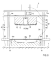
resin material 20 is formed, as shown inFIG. 8 , each of the folding backdevices 64 is actuated to elongate the folding backrod 64a, thereby folding back the periphery of thesurface cover member 30 along theperiphery 10c of thebase member 10. Thus, the folded backportion 30c of thesurface cover member 30 can be formed on theback surface 10b of thebase member 10. Further, at this time, the foamedresin material 20 can be partially squeezed out via the throughholes 12 formed in thebase member 10 to form a squeezed outportion 20b of the foamedresin material 20 on theback surface 10b of thebase member 10. - Next, as shown in
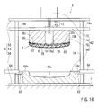
FIG. 9 , themain cylinder 70 is further actuated to elongate only theouter rod 72a without moving or elongating theinner rod 72b (i.e., without lifting the piston 78), so as to lower the base plate 74 (the upper die 76) until thedie surface 76a of theupper die 76 substantially contacts theback surface 10b of thebase member 10. As a result, the folded backportion 30c of thesurface cover member 30 can be pressed against theback surface 10b of thebase member 10 with interleaving the squeezed outportion 20b of the foamedresin material 20 therebetween. Thus, the folded backportion 30c of thesurface cover member 30 can be adhered to theback surface 10b of thebase member 10 via the squeezed outportion 20b of the foamedresin material 20. Naturally, this adhering process may preferably be performed before the foamedresin material 20 is completely set or cured. The foamedresin material 20 that is not completely set can be easily enter small irregularities in a surface of the folded backportion 30c of thesurface cover member 30, so that an anchor effect can be produced. Therefore, the folded backportion 30c of thesurface cover member 30 can be securely adhered to theback surface 10b of thebase member 10 due to the anchor effect of the foamedresin material 20. - Upon completion of foaming and curing of the foamed
resin material 20, theconsol lid 2 can be formed between theupper die 76 and thelower die 60. After theconsol lid 2 is formed, as shown inFIG. 10 , themain cylinder 70 is further actuated to contract the rod 72 (theouter rod 72a and theinner rod 72b), so that thebase plate 74 can be lifted. As a result, thelower die 60 and theupper die 76 attached to thebase plate 74 are opened. At this time, the formedconsol lid 2 is held on thedie surface 76a of theupper die 76 by engagement of the inserting theribs 14 formed in theback surface 10b of thebase member 10 and theengagement holes 78a formed in thepiston 78. Theconsol lid 2 can be easily disengaged from theupper die 76 by simply removing the inserting theribs 14 from theengagement holes 78a. Thus, theconsol lid 2 can be obtained (FIGS. 11 and 12 ). - According to the present method for manufacturing the
consol lid 2, the folded backportion 30c of thesurface cover member 30 can be adhered to theback surface 10b of thebase member 10 by the squeezed outportion 20b of the foamedresin material 20 when the foamedresin material 20 is formed. Therefore, it is not necessary to fix or connect the folded backportion 30c of thesurface cover member 30 to theback surface 10b of thebase member 10 by staples, nails or other such fixture members. That is, the method for manufacturing theconsol lid 2 can be simplified. As a result, manufacturing costs of theconsol lid 2 can be reduced. - Further, as previously described, the folded back
portion 30c of thesurface cover member 30 can be reliably adhered to theback surface 10b of thebase member 10 due to the anchor effect the foamedresin material 20. In addition, the folded backportion 30c of thesurface cover member 30 can be uniformly adhered to theback surface 10b of thebase member 10 without producing wrinkling. Therefore, the manufacturedconsol lid 2 can have a good appearance. - Various changes and modifications may be made to the present invention without departing from the scope of the invention. For example, in the embodiment, the folded back
portion 30c of thesurface cover member 30 can be adhered to theback surface 10b of thebase member 10 before the foamedresin material 20 is completely set or cured. However, the folded backportion 30c of thesurface cover member 30 can be adhered to theback surface 10b of thebase member 10 after the foamedresin material 20 is completely set or cured. Naturally, in this case, it is necessary to melt the cured squeezed outportion 20b of the foamedresin material 20 by heating the same in order to adhere the folded backportion 30c of thesurface cover member 30 to theback surface 10b of thebase member 10. - In the representative embodiment, the
consol lid 2 of the consol box is exemplified as the vehicle interior part. However, the vehicle interior part is not limited to theconsol lid 2 and may be an armrest. - Further, in this embodiment, the foamable polyurethane that can be produced by reaction of a polyol and an isocyanate is used as the foamable resin material M (the raw material of the foamed resin material 20). However, the foamable resin material M may be various adhesive foamable resin materials provided that they can be squeezed out via the through
holes 12 formed in thebase member 10 to form the squeezed outportion 20b of the foamedresin material 20 on theback surface 10b of thebase member 10. - Further, the foamable resin material M can be replaced with a material that cannot be chemically foamed. Naturally, in this case, such a material must be foamed or expanded by various foaming methods (e.g., a mechanical foaming method). Also, the foamable resin material M can be replaced with a material that is previously foamed.
- A representative example of the present invention has been described in detail with reference to the attached drawings. This detailed description is merely intended to teach a person of skill in the art further details for practicing preferred aspects of the present invention and is not intended to limit the scope of the invention. Only the claims define the scope of the claimed invention. Therefore, combinations of features and steps disclosed in the foregoing detailed description may not be necessary to practice the invention in the broadest sense, and are instead taught merely to particularly describe detailed representative examples of the invention. Moreover, the various features taught in this specification may be combined in ways that are not specifically enumerated in order to obtain additional useful embodiments of the present invention.
Claims (4)
- A vehicle interior part, comprising:a base member,a foamed resin material covering a surface of the base member, anda surface cover member covering a surface of the foamed resin material and a periphery of the base member,wherein the base member has a plurality of through holes that penetrates the same in a thickness direction thereof,wherein the foamed resin material has a squeezed out portion that is squeezed out via the through holes formed in the base member, andwherein the squeezed out portion is adhered to the surface cover member.
- The vehicle interior part as defined in claim 1, wherein the surface cover member has a folded back portion that is formed on a back surface of the base member, and wherein the squeezed out portion of the foamed resin material is adhered to the folded back portion of the surface cover member.
- A method for manufacturing a vehicle interior part including a base member having a plurality of through holes that penetrates the same in a thickness direction thereof, a foamed resin material covering a surface of the base member, and a surface cover member covering a surface of the foamed resin material and a periphery of the base member, comprising:setting the surface cover member in a forming die,disposing a foamable resin material on the set surface cover member,disposing the base member in the forming die such that the foamable resin material is positioned between the surface cover member and the base member,foaming the foamable resin material to form a foamed resin material,partially squeezing out the foamed resin material via the through holes formed in the base member to form a squeezed out portion of the foamed resin material, andadhering the squeezed out portion of the foamed resin material to the surface cover member.
- The method as defined in claim 3 further comprising:folding back a periphery of the surface cover member to form a folded back portion of the surface cover member on a back surface of the base member,wherein the squeezed out portion of the foamed resin material can be adhered to the folded back portion of the surface cover member in the adhering step.
Applications Claiming Priority (1)
| Application Number | Priority Date | Filing Date | Title |
|---|---|---|---|
| JP2010233372A JP5595866B2 (en) | 2010-10-18 | 2010-10-18 | Interior product for vehicle and method for manufacturing interior product for vehicle |
Publications (2)
| Publication Number | Publication Date |
|---|---|
| EP2441578A2 true EP2441578A2 (en) | 2012-04-18 |
| EP2441578A3 EP2441578A3 (en) | 2013-07-17 |
Family
ID=44532604
Family Applications (1)
| Application Number | Title | Priority Date | Filing Date |
|---|---|---|---|
| EP11173045.3A Withdrawn EP2441578A3 (en) | 2010-10-18 | 2011-07-07 | Vehicle interior part |
Country Status (3)
| Country | Link |
|---|---|
| US (1) | US8728604B2 (en) |
| EP (1) | EP2441578A3 (en) |
| JP (1) | JP5595866B2 (en) |
Cited By (3)
| Publication number | Priority date | Publication date | Assignee | Title |
|---|---|---|---|---|
| US20160176364A1 (en) * | 2014-12-18 | 2016-06-23 | Faurecia Interior Systems, Inc. | Vehicle interior panel with sculpted surface |
| FR3064564A1 (en) * | 2017-04-03 | 2018-10-05 | Cera Aps | INTERIOR TRIM PANEL OF MOTOR VEHICLE |
| EP4101700A1 (en) * | 2021-06-10 | 2022-12-14 | Eurostyle Systems Tech Center France | Method for coating a passenger compartment part of a motor vehicle |
Families Citing this family (4)
| Publication number | Priority date | Publication date | Assignee | Title |
|---|---|---|---|---|
| JP5955758B2 (en) * | 2012-12-17 | 2016-07-20 | 小島プレス工業株式会社 | Method for manufacturing a console door |
| JP6237149B2 (en) * | 2013-11-20 | 2017-11-29 | 大日本印刷株式会社 | Laminated sheet and manufacturing method thereof |
| US9623624B2 (en) * | 2014-11-10 | 2017-04-18 | Ford Global Technologies, Llc | Wrapped part assembly with edge/corner defining inserts |
| JP2023167459A (en) * | 2022-05-12 | 2023-11-24 | しげる工業株式会社 | Vehicular storage tray |
Citations (1)
| Publication number | Priority date | Publication date | Assignee | Title |
|---|---|---|---|---|
| JP2009067105A (en) | 2007-09-10 | 2009-04-02 | Honda Motor Co Ltd | Console Box |
Family Cites Families (3)
| Publication number | Priority date | Publication date | Assignee | Title |
|---|---|---|---|---|
| FR1164827A (en) * | 1956-11-09 | 1958-10-14 | Process for obtaining elastic fillings or padding, and all articles obtained by application of this process | |
| FR2578190B1 (en) * | 1985-03-01 | 1987-04-17 | Roth Sa Freres | METHOD FOR FILLING A COVER ON AN IN SITU MOLDED PIECE OF POLYURETHANE FOAM AND MOLDED PARTS THUS OBTAINED |
| JP5047420B2 (en) * | 2001-01-23 | 2012-10-10 | 株式会社イノアックコーポレーション | Foam molded body having skin material on both sides and molding method thereof |
-
2010
- 2010-10-18 JP JP2010233372A patent/JP5595866B2/en not_active Expired - Fee Related
-
2011
- 2011-07-07 EP EP11173045.3A patent/EP2441578A3/en not_active Withdrawn
- 2011-10-11 US US13/270,285 patent/US8728604B2/en not_active Expired - Fee Related
Patent Citations (1)
| Publication number | Priority date | Publication date | Assignee | Title |
|---|---|---|---|---|
| JP2009067105A (en) | 2007-09-10 | 2009-04-02 | Honda Motor Co Ltd | Console Box |
Cited By (5)
| Publication number | Priority date | Publication date | Assignee | Title |
|---|---|---|---|---|
| US20160176364A1 (en) * | 2014-12-18 | 2016-06-23 | Faurecia Interior Systems, Inc. | Vehicle interior panel with sculpted surface |
| US10471910B2 (en) * | 2014-12-18 | 2019-11-12 | Faurecia Interior Systems, Inc. | Vehicle interior panel with sculpted surface |
| FR3064564A1 (en) * | 2017-04-03 | 2018-10-05 | Cera Aps | INTERIOR TRIM PANEL OF MOTOR VEHICLE |
| EP4101700A1 (en) * | 2021-06-10 | 2022-12-14 | Eurostyle Systems Tech Center France | Method for coating a passenger compartment part of a motor vehicle |
| FR3123824A1 (en) * | 2021-06-10 | 2022-12-16 | Eurostyle Systems | Process for coating a passenger compartment part of a motor vehicle |
Also Published As
| Publication number | Publication date |
|---|---|
| JP5595866B2 (en) | 2014-09-24 |
| JP2012086608A (en) | 2012-05-10 |
| US20120094055A1 (en) | 2012-04-19 |
| US8728604B2 (en) | 2014-05-20 |
| EP2441578A3 (en) | 2013-07-17 |
Similar Documents
| Publication | Publication Date | Title |
|---|---|---|
| US8728604B2 (en) | Vehicle interior part | |
| US5324384A (en) | Apparatus for laminating a trim panel and folding a brim around the panel rim | |
| KR20140057206A (en) | Manufacturing a vehicle trim component via compression and injection molding | |
| JPH08318570A (en) | Vacuum forming simultaneous winding trimming device | |
| KR102270579B1 (en) | Punching apparatus for the formation of a design hole in leather or fabric | |
| US20080012384A1 (en) | Shock Absorber Made of Fiber Material | |
| US20150231871A1 (en) | Machine and method for forming a headliner | |
| CN108973150A (en) | The former and method of basic material and surface layer | |
| US20150084227A1 (en) | Method of manufacturing resin molded member | |
| US11673300B2 (en) | Foam and method of forming foam | |
| CN118847858A (en) | A molding device for automobile buckle reinforcement plate | |
| JP2001225339A (en) | Molding method and molding apparatus for laminated molded articles | |
| KR101353675B1 (en) | Hole pressing device of a floor carpet in automobile inner element | |
| JP5834797B2 (en) | Manufacturing method of hollow thin panel structure made of bendable or bendable resin | |
| KR200299852Y1 (en) | Device of joining interior material for a car door trim | |
| WO2009012313A1 (en) | Method of tensioning coverstock and forming vehicle interior components using retractable pins | |
| KR101809421B1 (en) | Apparatus for finishing edge of trunk mat | |
| EP2386398A1 (en) | A method for producing a foamed article | |
| CN106476077A (en) | The production technology of foaming carpet, production equipment and foaming die cutting die | |
| JP2001293737A (en) | Molding method and molding apparatus for laminated molded articles | |
| EP2764973A1 (en) | Expanded polypropylene foam-forming mold | |
| KR100957747B1 (en) | Automobile interior molding machine | |
| JP2007160736A (en) | Molding method and molding device for skin material laminated foamed resin molded product | |
| KR20160082315A (en) | Assembly devices of the car trunk injection molding | |
| CN211662539U (en) | Secondary compression injection molding device |
Legal Events
| Date | Code | Title | Description |
|---|---|---|---|
| PUAI | Public reference made under article 153(3) epc to a published international application that has entered the european phase |
Free format text: ORIGINAL CODE: 0009012 |
|
| AK | Designated contracting states |
Kind code of ref document: A2 Designated state(s): AL AT BE BG CH CY CZ DE DK EE ES FI FR GB GR HR HU IE IS IT LI LT LU LV MC MK MT NL NO PL PT RO RS SE SI SK SM TR |
|
| AX | Request for extension of the european patent |
Extension state: BA ME |
|
| PUAL | Search report despatched |
Free format text: ORIGINAL CODE: 0009013 |
|
| AK | Designated contracting states |
Kind code of ref document: A3 Designated state(s): AL AT BE BG CH CY CZ DE DK EE ES FI FR GB GR HR HU IE IS IT LI LT LU LV MC MK MT NL NO PL PT RO RS SE SI SK SM TR |
|
| AX | Request for extension of the european patent |
Extension state: BA ME |
|
| RIC1 | Information provided on ipc code assigned before grant |
Ipc: B29C 44/12 20060101ALI20130612BHEP Ipc: B60R 13/02 20060101ALI20130612BHEP Ipc: B32B 5/18 20060101ALI20130612BHEP Ipc: B32B 3/02 20060101ALI20130612BHEP Ipc: B32B 3/24 20060101AFI20130612BHEP Ipc: B32B 3/04 20060101ALI20130612BHEP Ipc: B32B 7/08 20060101ALI20130612BHEP |
|
| 17P | Request for examination filed |
Effective date: 20140116 |
|
| RBV | Designated contracting states (corrected) |
Designated state(s): AL AT BE BG CH CY CZ DE DK EE ES FI FR GB GR HR HU IE IS IT LI LT LU LV MC MK MT NL NO PL PT RO RS SE SI SK SM TR |
|
| 17Q | First examination report despatched |
Effective date: 20171127 |
|
| STAA | Information on the status of an ep patent application or granted ep patent |
Free format text: STATUS: THE APPLICATION IS DEEMED TO BE WITHDRAWN |
|
| 18D | Application deemed to be withdrawn |
Effective date: 20180410 |