EP2441398B1 - Bone plate aiming block - Google Patents
Bone plate aiming block Download PDFInfo
- Publication number
- EP2441398B1 EP2441398B1 EP11184357.9A EP11184357A EP2441398B1 EP 2441398 B1 EP2441398 B1 EP 2441398B1 EP 11184357 A EP11184357 A EP 11184357A EP 2441398 B1 EP2441398 B1 EP 2441398B1
- Authority
- EP
- European Patent Office
- Prior art keywords
- locking element
- bore
- bone
- rod
- drill guide
- Prior art date
- Legal status (The legal status is an assumption and is not a legal conclusion. Google has not performed a legal analysis and makes no representation as to the accuracy of the status listed.)
- Active
Links
Images



Classifications
-
- A—HUMAN NECESSITIES
- A61—MEDICAL OR VETERINARY SCIENCE; HYGIENE
- A61B—DIAGNOSIS; SURGERY; IDENTIFICATION
- A61B17/00—Surgical instruments, devices or methods
- A61B17/16—Instruments for performing osteoclasis; Drills or chisels for bones; Trepans
- A61B17/17—Guides or aligning means for drills, mills, pins or wires
- A61B17/1728—Guides or aligning means for drills, mills, pins or wires for holes for bone plates or plate screws
-
- A—HUMAN NECESSITIES
- A61—MEDICAL OR VETERINARY SCIENCE; HYGIENE
- A61B—DIAGNOSIS; SURGERY; IDENTIFICATION
- A61B17/00—Surgical instruments, devices or methods
- A61B17/16—Instruments for performing osteoclasis; Drills or chisels for bones; Trepans
- A61B17/17—Guides or aligning means for drills, mills, pins or wires
- A61B17/1739—Guides or aligning means for drills, mills, pins or wires specially adapted for particular parts of the body
- A61B17/1782—Guides or aligning means for drills, mills, pins or wires specially adapted for particular parts of the body for the hand or wrist
-
- A—HUMAN NECESSITIES
- A61—MEDICAL OR VETERINARY SCIENCE; HYGIENE
- A61B—DIAGNOSIS; SURGERY; IDENTIFICATION
- A61B17/00—Surgical instruments, devices or methods
- A61B17/56—Surgical instruments or methods for treatment of bones or joints; Devices specially adapted therefor
- A61B17/58—Surgical instruments or methods for treatment of bones or joints; Devices specially adapted therefor for osteosynthesis, e.g. bone plates, screws or setting implements
- A61B17/68—Internal fixation devices, including fasteners and spinal fixators, even if a part thereof projects from the skin
- A61B17/80—Cortical plates, i.e. bone plates; Instruments for holding or positioning cortical plates, or for compressing bones attached to cortical plates
-
- A—HUMAN NECESSITIES
- A61—MEDICAL OR VETERINARY SCIENCE; HYGIENE
- A61B—DIAGNOSIS; SURGERY; IDENTIFICATION
- A61B17/00—Surgical instruments, devices or methods
- A61B17/56—Surgical instruments or methods for treatment of bones or joints; Devices specially adapted therefor
- A61B17/58—Surgical instruments or methods for treatment of bones or joints; Devices specially adapted therefor for osteosynthesis, e.g. bone plates, screws or setting implements
- A61B17/68—Internal fixation devices, including fasteners and spinal fixators, even if a part thereof projects from the skin
- A61B17/80—Cortical plates, i.e. bone plates; Instruments for holding or positioning cortical plates, or for compressing bones attached to cortical plates
- A61B17/8061—Cortical plates, i.e. bone plates; Instruments for holding or positioning cortical plates, or for compressing bones attached to cortical plates specially adapted for particular bones
-
- Y—GENERAL TAGGING OF NEW TECHNOLOGICAL DEVELOPMENTS; GENERAL TAGGING OF CROSS-SECTIONAL TECHNOLOGIES SPANNING OVER SEVERAL SECTIONS OF THE IPC; TECHNICAL SUBJECTS COVERED BY FORMER USPC CROSS-REFERENCE ART COLLECTIONS [XRACs] AND DIGESTS
- Y10—TECHNICAL SUBJECTS COVERED BY FORMER USPC
- Y10T—TECHNICAL SUBJECTS COVERED BY FORMER US CLASSIFICATION
- Y10T408/00—Cutting by use of rotating axially moving tool
- Y10T408/55—Cutting by use of rotating axially moving tool with work-engaging structure other than Tool or tool-support
- Y10T408/567—Adjustable, tool-guiding jig
Definitions
- the present invention relates to a drill guide system for use with a bone plating system used in the fixation of fractures of long bones such as the femur, tibia, humerus and radius, including periarticular fractures. More specifically, the present invention encompasses a bone drill guide system that aids in the location of bone screws and drilling of pilot holes for the placement and intraoperative adjustment and fixation of the plate to the fractured bone.
- Typical fixation of a fracture of a long bone with a bone plate requires making an incision in the tissue, reducing the fracture, placing a bone plate on the fractured bone, and securing the bone plate to the bone with fixation elements such as screws.
- the bone plate immobilizes the fracture and keeps the bone in a correct position so as to allow the fracture to heal.
- bone plates have a bone contacting side and a side facing away from the bone with a plurality of holes or apertures extending between the two surfaces.
- These holes or apertures may be either threaded (for use with locking screws) or non-threaded (for use with regular screws) and may be circular or oblong in shape.
- bone stabilizing implants are frequently used.
- Such implants are for instance metal plates, which are made e.g. from surgical stainless steel or titanium. Plates used for such purposes are usually fixed to the bone parts by means of threaded screws, which are driven into the bone tissue after so-called pre-drilled or pilot-drilled holes have been generated in the bone tissue. These pre-drilled holes allow for a reliable screwing procedure whereby the risk of further destroying the bone with the screw is significantly reduced.
- aiming or targeting devices which work like a drilling jig.
- an aiming or targeting device is detachably fixed to the metal plate in a precise position.
- the plate has a head portion for placement adjacent the metaphysis of the bone and a shaft portion for placement against the diaphysis of the bone.
- the plate includes both locking (threaded) holes and non-locking holes.
- the locking holes are adapted to receive bone screws with threaded heads or proximal areas which engage the threads in the locking holes to thereby lock the screw to the plate. Bone screws without threaded heads can be then inserted into the non-locking holes or into the oblong holes which oblong holes permit the screws to be oriented at various angles.
- a drill guide system including a bone plate and aiming block is shown in U.S. Patent Application Publication No. 2009/0157086 .
- EP 2 072 016 A1 discloses a drill guide system including the features according to the preamble of claim 1.
- proximal means closer to the heart and the term “distal” means more distant from the heart.
- distal means more distant from the heart.
- inferior means toward the feet and the term “superior” means towards the head.
- anterior means towards the front part of the body or the face and the term “posterior” means towards the back of the body.
- medial means toward the midline of the body and the term “lateral” means away from the midline of the body.
- the invention relates to a drill guide system according to claim 1. Further embodiments of the invention are recited in the dependent claims.
- Instrumentation 10 includes a first locking element in the form of a locking element 12 with a sleeve 12a, a spreading pin or rod 36 and a drill guide block 14. Also shown is a bone plate 16 including a plurality of holes 18 for receiving bone screws (not shown) at one end thereof.
- the bone plate 16 may be angled or bent to match the bone anatomy.
- the bone plate 16 may also include a hole 18a spaced intermediate the bone plate along a longitudinal axis of plate 16. All of the bone plate holes may have an internal circumferential area of reduced diameter formed from a circumferential radially inwardly extending rib or protrusion 52 having a wedge shape.
- Guide block 14 includes a plurality of holes 22 which are alignable with the holes 18 of the bone plate and are adapted to receive either locking element 12 or a drill guide so that pilot holes may be drilled in the bone (for example a radius) on which bone plate 16 is to be mounted. Also shown mounted in guide block 14 is a second locking element 24 which is insertable into hole 18a of bone plate 16. As shown locking element 24 may be permanently mounted in block 14 or may be a removeable locking element similar to locking element 12 located in bone 22a.
- Locking element sleeve 12a includes a bore 60 and an expandable tip 38 received in one of the bone plate holes 18 or 18a holds the block 14 on the bone plate 16.
- FIGS. 2 and 3 there is shown an elevation view of the assembled locking element 12 having sleeve 12a and axially moveable rod 36.
- Axially moveable rod 36 includes head 34 with a drive socket 62 and is threadably received within locking element sleeve 12a.
- a slit 42 is provided in sleeve 12a so that tip 38 of locking element sleeve 12a can expand as the axially moveable rod 36 moves inwardly towards tip 38 upon rotation of head 34.
- Sleeve 12a has an anti-rotation element 102 adapted to be received within anti-rotation recesses 26 on the guide block 14 as shown in FIGS. 1A and 8 .
- Anti-rotation element 102 includes a threaded shaft 100 insertable in a threaded bore 103 in sleeve 12a. Shown in FIG. 3 are the two bifurcated sections 46 and 48 of sleeve 12a formed by slit 42.
- FIG. 3 there is an enlarged view of the tip area 38 of locking element sleeve 12a shown in FIG. 2 .
- This includes lip 54 and recessed area 53 that includes two of the bifurcated elements 46, 48.
- axially moveable rod 36 includes a threaded section 39 which is engagable with a threaded section 41 in the upper end of bore 60 of locking element sleeve 12a.
- axially moveable rod 36 may be moved into and out of engagement with a circumferential internal angled surface 90 of locking element sleeve 12a shown in FIG. 5 .
- FIG. 4 there is shown an elevation view of the locking element sleeve 12a with FIG. 7 showing an elevation view of the axially moveable rod 36 including a head 34 and threaded section 39 and angled or beveled end portion 92.
- FIG. 5 there is shown an assembly of the locking element sleeve 12a of FIG. 4 and the axially moveable rod 36 of FIG. 7 to form locking element 12 shown in cross-section.
- FIG. 7 there is a cross-sectional view of locking element 12 along lines 6-6 of FIG. 4 showing a pair of slots 42 and 44 forming four bifurcated segments 45, 46, 47 and 48. While four such segments are shown, two, three or more than four segments can be formed by the appropriate number of slots.
- Locking element 12 also includes rotational stability pin 102 which has a head 105 and shaft 100 threadably mounted in bore 103 in the wall defining bore 60 of locking element sleeve 12a.
- rotational stability pin 102 is received within slot 26 formed in the aiming block 14 to prevent rotation of locking element within the aiming block bore 18 when applying torque to head 34 of axially moveable rod 36.
- first locking element 12 This includes head or rotatable portion 34 which rotates threaded actuating rod 36 in threaded bore 60 best shown in FIGS. 2 and 8 which moves rod 36 axially within an expandable tip 38 of first locking element sleeve 12a.
- Sleeve 12a and rod 36 may be made of a metal or polymer such as PEEK.
- the expandable tip 38 has an internal stepped or angled surface 92 which engages a conical tip or angled surface 90 of rod 36.
- the expandable tip 38 can be bifurcated as shown in FIG. 6 and may contain three, four or even more branches.
- the branches are separated by slits or slots 42, 44 extending from an open end 43 of expandable tip 38 towards threaded portion 41.
- slits or slots 42, 44 which form four tip branches 45, 46, 47 and 48.
- the slits or slots allow the branches to deform outwardly in a resilient fashion such that when the actuating rod 36 is moved out of engagement with stepped surface 92, the branches spring inwardly.
- bone plate 16 includes bores or holes 18 each having an inner wall 50 including a radially inwardly extending circumferential rib 52 having tip 51.
- Bone plate 16 has a bone contacting surface 55 and an opposite surface 57.
- the bone contacting surface 55 of the bone plate 16 surrounding hole 18 is recessed such that the rib 52 is located intermediate the outer bone plate surface 57 and the bone contacting bone plate surface 55.
- the end or tip 38 of first locking element 12 includes a lip 54 defining a recess 53 for receiving tip 51 of circumferential rib 52 of bone plate hole 18 inner wall 50.
- Inner bore 60 of the first locking element sleeve 12a is threaded at 41 to receive the threaded outer surface 39 on actuating rod or pin 36.
- Pin or rod 36 head 34 has a drive socket or other feature 62 which can be rotated using a standard tool (not shown) such as a hex drive. Rotation of rod 36 via head 34 rotates rod 36 moving it into and out of engagement with inner shoulder 90 of tip 38 and causes branches 45 through 48 to expand outwardly such that lip 54 engages tip 51 and locks the first locking element 12 and block 14 to bone plate 16 via rib 52 and head 34. Branches 45-48 are resilient and spring inwardly when rod 36 is moved out of engagement with surface 90.
- FIG. 9 there is shown a bottom view of the locking element 12 and axially movable rod 36 mounted in plate 16 with recess 53 engaging tip 51 of protrusion 52 of bone plate 16. As shown there are only two bifurcated elements 46 and 48 in FIG. 9 .
- FIGS. 10-13 there is shown an embodiment of the locking element generally denoted as 112 and a sleeve element 112a and axially movable rod 136 of the present invention.
- FIG. 10 there is shown a side elevation view of the embodiment 112 with the axially movable rod 136 in a first position in which the bifurcated arms 146 and 148 of locking element sleeve 112a, which are identical to the bifurcated portions 46 and 48 of locking element sleeve 12a would be in an expanded position.
- FIG. 11 there is shown a cross-sectional view of FIG.
- axially moveable rod 136 includes a threaded portion 139 and the locking element sleeve 112a includes a threaded portion 141 which engage so that rotation of head 134 can move the rod 136 with respect to bore 160 of locking element sleeve 112a in an axial direction.
- first stop element 145 which protrudes outwardly of rod 136 and extends circumferentially therearound.
- Stop element 145 includes a downwardly facing circumferential surface 190 which can engage angled or slanted surface 192 of locking element sleeve 112a to expand the bifurcated tip 138 via slit or slot 142 of locking element sleeve 112a.
- the axially moveable rod 136 can have a second stop element or surface 194 engagable with upper surface 193 at tip 104 of anti-rotation pin 102. The engagement of surface 194 and upper surface 193 tip 104 limits the downward axial movement of rod 136 as shown in FIG. 11 thus placing a limit on the expansion of the bifurcated tip 138.
- FIG. 12 there is shown the assembly of axially moveable rod 136 and locking element sleeve 112a with the axially moveable rod in a second retracted position within bore 160 of locking element sleeve 112a.
- FIG. 13 there is shown that, in this retracted position, the complete disassembly of rod 136 from locking element sleeve 112a is prevented by the engagement of an upwardly facing surface 196 of stop element 145 with the lower surface 195 tip 104 of anti-rotation element 102.
- anti-rotation element 102 includes a threaded section 100 which engages threaded bore 103 in locking element sleeve 112a so that by rotation of head 105 tip 104 may be moved axially out of bore 160 of locking element sleeve 112a. In this position rod 136 may either be inserted or removed from locking element sleeve 112a.
- the threaded portions 139 and 141 are sized to permit the engagement of surface 196 and tip 104 prior to the threads disengaging.
- the length of rod 36 can be designed such that the engagement of bottom surface 107 of head 34 engages upwardly facing surface 109 of aiming block 14 to limit the expansion of bifurcated arms 45-48.
- the length of rod 36 will have to be sufficient so that recess 53 of the bifurcated tip 38 locks with tip 51 of bone plate protrusion 52 prior to surface 107 engaging surface 109. This has the added advantage of tightly clamping aiming block 14 to bone plate 16 by rotation of head 34 of axially moveable rod 36.
- FIGS. 14-16 there is shown a method of forming pilot holes.
- the bone plate 16 is located on an end of a long bone such as a radius 200 and the block 14 is placed on bone plate 16 with its guide bores 22 aligned with the holes 18 in plate 16.
- the guide block 14 is held onto the plate by the first and second locking elements 12 and 24 respectively with the first locking elements extending through one of the guide bores 22. Any convenient guide bore 22 may be chosen.
- a drill guide 110 includes a handle 152 a tubular guide 114 which receives a drill bit (not shown).
- the drill bit may be powered by a pneumatic or electric drill and is adapted to form holes in the bone for bone screws as shown in FIG. 14 .
- the drill guide is moved from one bore 22 to the next bore 22 and pilot holes are drilled in all the bone plate holes 18.
- the last pilot hole is drilled in the guide bore 22 which initially had the first locking element 12.
- Locking element 12 is placed in a guide bore which has been already used to drill a pilot hole and the drill guide is placed in the hole just vacated by first locking element 12 and that pilot hole is drilled.
- FIG. 15 there is shown the use of two locking inserts 12 to hold the aiming block 14 to plate 16.
- locking element 24 may be eliminated.
- both locking elements 12 will have to be removed and relocated to drill all the pilot holes through bores 22 and 18.
- a depth gauge 116 of any conventional type and is used to measure the depth of the pilot hole drilled. If that hole is not drilled deeply enough the hole may be re-drilled using the drill guide 110.
- FIG. 16 shows the plate 16 mounted on bone 200 with the bone screws 120 set in the plate 16 thereby locking the upper end of the plate to the bone.
Landscapes
- Health & Medical Sciences (AREA)
- Surgery (AREA)
- Life Sciences & Earth Sciences (AREA)
- Orthopedic Medicine & Surgery (AREA)
- Biomedical Technology (AREA)
- Nuclear Medicine, Radiotherapy & Molecular Imaging (AREA)
- Oral & Maxillofacial Surgery (AREA)
- Engineering & Computer Science (AREA)
- Dentistry (AREA)
- Heart & Thoracic Surgery (AREA)
- Medical Informatics (AREA)
- Molecular Biology (AREA)
- Animal Behavior & Ethology (AREA)
- General Health & Medical Sciences (AREA)
- Public Health (AREA)
- Veterinary Medicine (AREA)
- Surgical Instruments (AREA)
Description
- The present invention relates to a drill guide system for use with a bone plating system used in the fixation of fractures of long bones such as the femur, tibia, humerus and radius, including periarticular fractures. More specifically, the present invention encompasses a bone drill guide system that aids in the location of bone screws and drilling of pilot holes for the placement and intraoperative adjustment and fixation of the plate to the fractured bone.
- Typical fixation of a fracture of a long bone with a bone plate requires making an incision in the tissue, reducing the fracture, placing a bone plate on the fractured bone, and securing the bone plate to the bone with fixation elements such as screws. The bone plate immobilizes the fracture and keeps the bone in a correct position so as to allow the fracture to heal.
- Typically, bone plates have a bone contacting side and a side facing away from the bone with a plurality of holes or apertures extending between the two surfaces. These holes or apertures may be either threaded (for use with locking screws) or non-threaded (for use with regular screws) and may be circular or oblong in shape.
- In order to allow for a reliable stabilization of a broken bone in its normal position, special bone stabilizing implants are frequently used. Such implants are for instance metal plates, which are made e.g. from surgical stainless steel or titanium. Plates used for such purposes are usually fixed to the bone parts by means of threaded screws, which are driven into the bone tissue after so-called pre-drilled or pilot-drilled holes have been generated in the bone tissue. These pre-drilled holes allow for a reliable screwing procedure whereby the risk of further destroying the bone with the screw is significantly reduced.
- In order to facilitate the drilling of these pre-drilled holes there are known so-called aiming or targeting devices, which work like a drilling jig. Thereby, an aiming or targeting device is detachably fixed to the metal plate in a precise position.
- One such bone plate is shown in
U.S. Patent No. 6,623,486 in which the plate has a head portion for placement adjacent the metaphysis of the bone and a shaft portion for placement against the diaphysis of the bone. The plate includes both locking (threaded) holes and non-locking holes. The locking holes are adapted to receive bone screws with threaded heads or proximal areas which engage the threads in the locking holes to thereby lock the screw to the plate. Bone screws without threaded heads can be then inserted into the non-locking holes or into the oblong holes which oblong holes permit the screws to be oriented at various angles. - A drill guide system including a bone plate and aiming block is shown in
U.S. Patent Application Publication No. 2009/0157086 . -
EP 2 072 016 A1 discloses a drill guide system including the features according to the preamble ofclaim 1. - As used herein, when referring to bones or other parts of the body, the term "proximal" means closer to the heart and the term "distal" means more distant from the heart. The term "inferior" means toward the feet and the term "superior" means towards the head. The term "anterior" means towards the front part of the body or the face and the term "posterior" means towards the back of the body. The term "medial" means toward the midline of the body and the term "lateral" means away from the midline of the body.
- The invention relates to a drill guide system according to
claim 1. Further embodiments of the invention are recited in the dependent claims. -
-
FIG. 1 is an exploded view of a bone plate instrumentation including a bone plate, drill guide aiming block and a first locking element adapted to lock the drill guide block to the bone plate; -
FIG. 1A is a top view of the aiming block placed on top of the bone plate prior to insertion of any locking elements; -
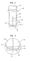
FIG. 2 is a side elevation view of the locking element and axially moveable rod; -
FIG. 3 is a partial cross-sectional view of the tip of the locking element ofFIG. 2 ; -
FIG. 4 is an elevation view of the bifurcated locking element; -
FIG. 5 is a cross-sectional view of the locking element ofFIG. 4 with the axially movable rod threadably mounted therein; -
FIG. 6 is a cross-sectional view of the bifurcated locking element along lines 6-6 ofFIG. 4 ; -
FIG. 7 is a side elevation view of an axially movable rod; -
FIG. 8 is a cross-sectional view of the locking element and axially moveable rod ofFIGS. 4-7 mounted in an aiming block and connected to a bone plate; -
FIG. 9 is an isometric bottom view of the bone plate shown inFIG. 8 including the locking element and axially moveable rod of the present invention; -
FIG. 10 is a side elevation view of the locking element and axially moveable rod of an embodiment of the present invention in a first position. -
FIG. 11 is a cross-sectional view of the locking element and rod ofFIG. 10 in the first position; -
FIG. 12 is a side elevation view of the locking element and axially moveable rod ofFIG. 10 in a second position; -
FIG. 13 is a cross-sectional view of the locking element and axially moveable rod ofFIG. 12 ; -
FIG. 14 shows the step of placing a drill guide in the guide block being held in place by a locking element; -
FIG. 15 shows the step of placing a drill guide in the guide block having two locking elements and drilling a pilot hole; and -
FIG. 16 shows a bone plate assembled to a distal radius with bone screws. - Referring to
FIG. 1 and 1A there is shown an exploded view of the instrumentation generally denoted as 10.Instrumentation 10 includes a first locking element in the form of alocking element 12 with asleeve 12a, a spreading pin orrod 36 and adrill guide block 14. Also shown is abone plate 16 including a plurality ofholes 18 for receiving bone screws (not shown) at one end thereof. Thebone plate 16 may be angled or bent to match the bone anatomy. Thebone plate 16 may also include ahole 18a spaced intermediate the bone plate along a longitudinal axis ofplate 16. All of the bone plate holes may have an internal circumferential area of reduced diameter formed from a circumferential radially inwardly extending rib orprotrusion 52 having a wedge shape.Guide block 14 includes a plurality ofholes 22 which are alignable with theholes 18 of the bone plate and are adapted to receive eitherlocking element 12 or a drill guide so that pilot holes may be drilled in the bone (for example a radius) on whichbone plate 16 is to be mounted. Also shown mounted inguide block 14 is asecond locking element 24 which is insertable intohole 18a ofbone plate 16. As shownlocking element 24 may be permanently mounted inblock 14 or may be a removeable locking element similar tolocking element 12 located inbone 22a. - Referring to
FIGS. 2-9 there is shown a first locking element generally denoted as 12 including an axiallymovable rod 36.Locking element sleeve 12a includes abore 60 and anexpandable tip 38 received in one of thebone plate holes block 14 on thebone plate 16. - Referring to
FIGS. 2 and 3 there is shown an elevation view of the assembledlocking element 12 havingsleeve 12a and axiallymoveable rod 36.
Axiallymoveable rod 36 includeshead 34 with adrive socket 62 and is threadably received withinlocking element sleeve 12a. As can be seen aslit 42 is provided insleeve 12a so thattip 38 oflocking element sleeve 12a can expand as the axiallymoveable rod 36 moves inwardly towardstip 38 upon rotation ofhead 34. Sleeve 12a has ananti-rotation element 102 adapted to be received withinanti-rotation recesses 26 on theguide block 14 as shown inFIGS. 1A and8 .Anti-rotation element 102 includes a threadedshaft 100 insertable in a threadedbore 103 insleeve 12a. Shown inFIG. 3 are the two bifurcatedsections sleeve 12a formed byslit 42. - Referring again to
FIG. 3 there is an enlarged view of thetip area 38 oflocking element sleeve 12a shown inFIG. 2 . This includeslip 54 and recessedarea 53 that includes two of thebifurcated elements - Referring to
FIGS. 4-7 axiallymoveable rod 36 includes a threadedsection 39 which is engagable with a threadedsection 41 in the upper end ofbore 60 of lockingelement sleeve 12a. Thus by the rotation ofhead 34 axiallymoveable rod 36 may be moved into and out of engagement with a circumferential internalangled surface 90 of lockingelement sleeve 12a shown inFIG. 5 . - Referring to
FIG. 4 there is shown an elevation view of the lockingelement sleeve 12a withFIG. 7 showing an elevation view of the axiallymoveable rod 36 including ahead 34 and threadedsection 39 and angled orbeveled end portion 92. Referring toFIG. 5 there is shown an assembly of the lockingelement sleeve 12a ofFIG. 4 and the axiallymoveable rod 36 ofFIG. 7 to form lockingelement 12 shown in cross-section. Referring toFIG. 7 there is a cross-sectional view of lockingelement 12 along lines 6-6 ofFIG. 4 showing a pair ofslots 42 and 44 forming fourbifurcated segments - Referring to
FIG. 8 there is shown a lockingelement 12 with thetip 38 ofsleeve 12a expanded to engage a tip 51 ofprotrusion 52 inbone plate hole 18. This expansion is caused by movement ofrod 36 axially downwardly such thatsurface 92 on axiallymovable rod 36 engages a stepped or slantedsurface portion 90 on theinner bore 60 of lockingelement sleeve 12a. Lockingelement 12 also includesrotational stability pin 102 which has ahead 105 andshaft 100 threadably mounted inbore 103 in the wall defining bore 60 of lockingelement sleeve 12a. Thus, by rotation of anti-rotation element 102 atip 104 ofanti-rotation element 102 can be moved transversely to an axis ofbore 60.Head 105 ofrotational stability pin 100 is received withinslot 26 formed in the aimingblock 14 to prevent rotation of locking element within the aiming block bore 18 when applying torque to head 34 of axiallymoveable rod 36. - Again referring to
FIGS. 2-9 there is shown further details of thefirst locking element 12. This includes head orrotatable portion 34 which rotates threadedactuating rod 36 in threaded bore 60 best shown inFIGS. 2 and8 which movesrod 36 axially within anexpandable tip 38 of firstlocking element sleeve 12a.Sleeve 12a androd 36 may be made of a metal or polymer such as PEEK. Theexpandable tip 38 has an internal stepped or angledsurface 92 which engages a conical tip or angledsurface 90 ofrod 36. Theexpandable tip 38 can be bifurcated as shown inFIG. 6 and may contain three, four or even more branches. The branches are separated by slits orslots 42, 44 extending from an open end 43 ofexpandable tip 38 towards threadedportion 41. InFIGS. 4 and 6 there are two slits orslots 42 and 44 which form fourtip branches rod 36 is moved out of engagement with steppedsurface 92, the branches spring inwardly. - As best shown in
FIGS. 2 and8 ,bone plate 16 includes bores or holes 18 each having aninner wall 50 including a radially inwardly extendingcircumferential rib 52 having tip 51.Bone plate 16 has abone contacting surface 55 and anopposite surface 57. InFIGS. 2 and8 thebone contacting surface 55 of thebone plate 16 surroundinghole 18 is recessed such that therib 52 is located intermediate the outerbone plate surface 57 and the bone contactingbone plate surface 55. As best seen inFIG. 3 the end ortip 38 offirst locking element 12 includes alip 54 defining arecess 53 for receiving tip 51 ofcircumferential rib 52 ofbone plate hole 18inner wall 50. Inner bore 60 of the firstlocking element sleeve 12a is threaded at 41 to receive the threadedouter surface 39 on actuating rod orpin 36. Pin orrod 36head 34 has a drive socket orother feature 62 which can be rotated using a standard tool (not shown) such as a hex drive. Rotation ofrod 36 viahead 34 rotatesrod 36 moving it into and out of engagement withinner shoulder 90 oftip 38 and causesbranches 45 through 48 to expand outwardly such thatlip 54 engages tip 51 and locks thefirst locking element 12 and block 14 tobone plate 16 viarib 52 andhead 34. Branches 45-48 are resilient and spring inwardly whenrod 36 is moved out of engagement withsurface 90. - Referring to
FIG. 9 there is shown a bottom view of the lockingelement 12 and axiallymovable rod 36 mounted inplate 16 withrecess 53 engaging tip 51 ofprotrusion 52 ofbone plate 16. As shown there are only twobifurcated elements FIG. 9 . - Referring to
FIGS. 10-13 there is shown an embodiment of the locking element generally denoted as 112 and asleeve element 112a and axiallymovable rod 136 of the present invention. Referring toFIG. 10 there is shown a side elevation view of theembodiment 112 with the axiallymovable rod 136 in a first position in which the bifurcatedarms element sleeve 112a, which are identical to thebifurcated portions element sleeve 12a would be in an expanded position. Referring toFIG. 11 there is shown a cross-sectional view ofFIG. 10 along lines 11-11showing head 134 includinghead socket 162 ofrod 136 in its position for expanding the bifurcated sections of lockingelement sleeve 112a. Again, axiallymoveable rod 136 includes a threadedportion 139 and the lockingelement sleeve 112a includes a threadedportion 141 which engage so that rotation ofhead 134 can move therod 136 with respect to bore 160 of lockingelement sleeve 112a in an axial direction. As shown inFIG. 11 there is afirst stop element 145 which protrudes outwardly ofrod 136 and extends circumferentially therearound.Stop element 145 includes a downwardly facingcircumferential surface 190 which can engage angled or slantedsurface 192 of lockingelement sleeve 112a to expand thebifurcated tip 138 via slit or slot 142 of lockingelement sleeve 112a. The axiallymoveable rod 136 can have a second stop element orsurface 194 engagable withupper surface 193 attip 104 ofanti-rotation pin 102. The engagement ofsurface 194 andupper surface 193tip 104 limits the downward axial movement ofrod 136 as shown inFIG. 11 thus placing a limit on the expansion of thebifurcated tip 138. - Referring to
FIG. 12 there is shown the assembly of axiallymoveable rod 136 and lockingelement sleeve 112a with the axially moveable rod in a second retracted position withinbore 160 of lockingelement sleeve 112a. Referring toFIG. 13 there is shown that, in this retracted position, the complete disassembly ofrod 136 from lockingelement sleeve 112a is prevented by the engagement of an upwardly facingsurface 196 ofstop element 145 with thelower surface 195tip 104 ofanti-rotation element 102. Preferablyanti-rotation element 102 includes a threadedsection 100 which engages threadedbore 103 in lockingelement sleeve 112a so that by rotation ofhead 105tip 104 may be moved axially out ofbore 160 of lockingelement sleeve 112a. In thisposition rod 136 may either be inserted or removed from lockingelement sleeve 112a. Obviously the threadedportions surface 196 andtip 104 prior to the threads disengaging. - As shown in
FIGS. 4-8 with therod 36 having nostop element 145 the length ofrod 36 can be designed such that the engagement ofbottom surface 107 ofhead 34 engages upwardly facingsurface 109 of aimingblock 14 to limit the expansion of bifurcated arms 45-48. The length ofrod 36 will have to be sufficient so thatrecess 53 of thebifurcated tip 38 locks with tip 51 ofbone plate protrusion 52 prior tosurface 107engaging surface 109. This has the added advantage of tightly clamping aimingblock 14 tobone plate 16 by rotation ofhead 34 of axiallymoveable rod 36. - Referring to
FIGS. 14-16 there is shown a method of forming pilot holes.
Initially, thebone plate 16 is located on an end of a long bone such as a radius 200 and theblock 14 is placed onbone plate 16 with its guide bores 22 aligned with theholes 18 inplate 16. Theguide block 14 is held onto the plate by the first andsecond locking elements FIG. 14 adrill guide 110 includes a handle 152 atubular guide 114 which receives a drill bit (not shown). The drill bit may be powered by a pneumatic or electric drill and is adapted to form holes in the bone for bone screws as shown inFIG. 14 . The drill guide is moved from one bore 22 to thenext bore 22 and pilot holes are drilled in all the bone plate holes 18. The last pilot hole is drilled in the guide bore 22 which initially had thefirst locking element 12. Lockingelement 12 is placed in a guide bore which has been already used to drill a pilot hole and the drill guide is placed in the hole just vacated by first lockingelement 12 and that pilot hole is drilled. - Referring to
FIG. 15 there is shown the use of two lockinginserts 12 to hold the aimingblock 14 toplate 16. In thiscase locking element 24 may be eliminated. Obviously in this case both lockingelements 12 will have to be removed and relocated to drill all the pilot holes throughbores FIG. 15 there is shown adepth gauge 116 of any conventional type and is used to measure the depth of the pilot hole drilled. If that hole is not drilled deeply enough the hole may be re-drilled using thedrill guide 110. -
FIG. 16 shows theplate 16 mounted on bone 200 with the bone screws 120 set in theplate 16 thereby locking the upper end of the plate to the bone. - Although the invention herein has been described with reference to particular embodiments, it is to be understood that these embodiments are merely illustrative of the principles and applications of the present invention. It is therefore to be understood that numerous modifications may be made to the illustrative embodiments and that other arrangements may be devised without departing from the scope of the present invention as defined by the appended claims.
Claims (12)
- A drill guide system for a bone plate (16) having holes therethrough for receiving bone screws, comprising:a guide block (14) having at least two drill guide bores (22), each bore alignable with a bone screw receiving hole (18) in a bone plate (16), the guide block having a first surface for contacting a surface of a bone plate (16) and a second surface opposite the first surface;a locking element (112) extending through a drill guide bore (22) into the bone plate bone screw receiving hole (18), the locking element (112) having a bore (160) with a threaded portion (141) and a bifurcated tip (138) for engaging an inwardly extending protrusion (52) on the wall of a bone screw receiving hole (18) in the bone plate (16), the tip (138) having an outwardly extending flange engaging a surface of the bone plate protrusion facing a bone contacting surface of the bone plate (16);an axially movable rod (136) having a threaded portion (139) mounted in the threaded bore portion of the locking element (112), the rod (136) having a head (134) engaging the second surface of the guide block (14) and a tip engaging a bore in the tip (138) of the locking element (112) and capable of spreading sections of the bifurcated tip on axial movement of the rod (136) prior to the rod head contacting the second surface of the guide block (14), characterized in that the axially moveable rod (136) has an outwardly extending first stop element surface (196) and that the locking element (112) has a stop pin (102) extending through a wall of the locking element in a direction transverse to the bore therein into the bore of the locking element (112) the locking element stop pin (102) engagable with the axially moveable rod first stop surface on movement of the rod element head (134) away from the second surface of the guide block (14).
- The drill guide system as set forth in claim 1 wherein the stop pin (102) on the locking element (112) is moveable in the direction transverse to the bore in the locking element (112) and is engageable with the first stop surface on the axially moveable rod (136) in a first position and is not engagable with the first stop element in a second position.
- The drill guide system as set forth in claims 1 and 2 comprising
a bone plate (16) having an outer surface, a bone-contacting surface for application to a bone, first and second bone screw receiving holes (18) extending from the outer surface to the bone-contacting surface, and the first and second bone screw receiving holes (18) having a circumferential wall including an inwardly extending protrusion (52), the first bone screw receiving hole extending along a first axis, the second bone screw receiving hole extending along a second axis;
the guide block (14) having a recess (26) extending from the upper surface towards the lower surface and intersecting the drill guide bore (22), the stop pin (102) having a head received in the recess when inserted into the bore (160) of the locking element (112). - The drill guide system as set forth in claim 3, wherein the first and second bone screw receiving holes (18) are non-threaded.
- The drill guide system as set forth in claims 1-4 wherein the axially moveable rod (136) has a second outwardly extending stop surface.
- The drill guide system as set forth in claims 1-5 wherein the moveable stop pin (102) is threaded and is mounted in a threaded bore (103) in the wall of the locking element (112) and moveable in a direction transverse to the locking element bore (103) by rotation of the moveable stop pin (102) into and out of the locking element bore.
- The drill guide system as set forth in claim 5 wherein the axially moveable rod second stop surface (194) engages the moveable stop pin (102) on the locking element on movement of the rod element head towards the second surface of the guide block (14).
- The drill guide system as set forth in claim 1 wherein the bifurcated tip portion (138) of the locking element (112) has four sections (45, 46, 47, 48) separated by axially extending slits (42, 44) extending from the locking element tip (138) towards the locking element head.
- The drill guide system as set forth in claim 8 wherein the moveable stop pin (102) is located between the locking element head and an end of the slits (42, 44).
- The drill guide system as set forth in claim 1 wherein the moveable stop pin (102) has a head portion (105) for engaging an anti-rotation feature (26) in the guide block bore (22).
- The drill guide system as set forth in claim 1 wherein the moveable stop pin (102) extends in a direction perpendicular to an axis of the axially extending bore (160) in the locking element (112).
- The drill guide system of claim 2 wherein the axially moveable rod (138) is insertable and removable from the locking element bore (160) only when the stop pin (102) is in the second position.
Applications Claiming Priority (2)
| Application Number | Priority Date | Filing Date | Title |
|---|---|---|---|
| PCT/US2010/052425 WO2012050572A1 (en) | 2010-10-13 | 2010-10-13 | Bone plate aiming block |
| US13/079,302 US8523862B2 (en) | 2011-04-04 | 2011-04-04 | Bone plate aiming block |
Publications (2)
| Publication Number | Publication Date |
|---|---|
| EP2441398A1 EP2441398A1 (en) | 2012-04-18 |
| EP2441398B1 true EP2441398B1 (en) | 2015-09-30 |
Family
ID=46928203
Family Applications (1)
| Application Number | Title | Priority Date | Filing Date |
|---|---|---|---|
| EP11184357.9A Active EP2441398B1 (en) | 2010-10-13 | 2011-10-07 | Bone plate aiming block |
Country Status (2)
| Country | Link |
|---|---|
| US (1) | US8523862B2 (en) |
| EP (1) | EP2441398B1 (en) |
Families Citing this family (59)
| Publication number | Priority date | Publication date | Assignee | Title |
|---|---|---|---|---|
| US8523862B2 (en) * | 2011-04-04 | 2013-09-03 | Stryker Leibinger Gmbh & Co. Kg | Bone plate aiming block |
| WO2012050572A1 (en) | 2010-10-13 | 2012-04-19 | Stryker Leibinger Gmbh & Co., Kg. | Bone plate aiming block |
| US9050151B2 (en) * | 2012-03-06 | 2015-06-09 | Stryker Trauma Sa | Bone plate and aiming block |
| EP2961338B1 (en) * | 2012-10-15 | 2022-01-05 | Dynamic Spine, LLC | Orthopaedic device |
| ES2710339T3 (en) | 2012-12-28 | 2019-04-24 | Paragon 28 Inc | Alignment guide system |
| WO2015094409A1 (en) * | 2013-12-20 | 2015-06-25 | Paragon 28, Inc. | Alignment guide apparatus, methods and systems |
| AU2014229500B2 (en) | 2013-03-11 | 2018-05-31 | Embark Enterprises, Inc. | Quadruped stifle stabilization system |
| US9468479B2 (en) | 2013-09-06 | 2016-10-18 | Cardinal Health 247, Inc. | Bone plate |
| CN106061412B (en) * | 2014-01-08 | 2019-09-20 | 史密夫和内修有限公司 | Drill steering system |
| USD735861S1 (en) * | 2014-03-10 | 2015-08-04 | Embark Enterprises Inc. | Quadruped stifle stabilization assembly |
| US9615839B2 (en) | 2014-03-18 | 2017-04-11 | Howmedica Osteonics Corp. | Shape-fit glenoid reaming systems and methods |
| USD779065S1 (en) | 2014-10-08 | 2017-02-14 | Nuvasive, Inc. | Anterior cervical bone plate |
| US11065042B2 (en) | 2015-02-04 | 2021-07-20 | Flower Orthopedics Corporation | Bone plate and guide block and attachment mechanism thereof |
| US11076898B2 (en) | 2015-08-27 | 2021-08-03 | Globus Medical, Inc. | Proximal humeral stabilization system |
| US10687874B2 (en) | 2015-08-27 | 2020-06-23 | Globus Medical, Inc | Proximal humeral stabilization system |
| US11197682B2 (en) | 2015-08-27 | 2021-12-14 | Globus Medical, Inc. | Proximal humeral stabilization system |
| US10130402B2 (en) | 2015-09-25 | 2018-11-20 | Globus Medical, Inc. | Bone fixation devices having a locking feature |
| US9974581B2 (en) | 2015-11-20 | 2018-05-22 | Globus Medical, Inc. | Expandable intramedullary systems and methods of using the same |
| US9795411B2 (en) | 2016-03-02 | 2017-10-24 | Globus Medical, Inc. | Fixators for bone stabilization and associated systems and methods |
| US10531905B2 (en) | 2016-04-19 | 2020-01-14 | Globus Medical, Inc. | Implantable compression screws |
| US11141204B2 (en) | 2016-08-17 | 2021-10-12 | Globus Medical Inc. | Wrist stabilization systems |
| US10751098B2 (en) | 2016-08-17 | 2020-08-25 | Globus Medical Inc. | Stabilization systems |
| US12588937B2 (en) | 2016-08-17 | 2026-03-31 | Globus Medical, Inc. | Volar distal radius stabilization system |
| US11331128B2 (en) | 2016-08-17 | 2022-05-17 | Globus Medical Inc. | Distal radius stabilization system |
| US10687873B2 (en) | 2016-08-17 | 2020-06-23 | Globus Medical Inc. | Stabilization systems |
| US11197701B2 (en) | 2016-08-17 | 2021-12-14 | Globus Medical, Inc. | Stabilization systems |
| US10575884B2 (en) | 2016-08-17 | 2020-03-03 | Globus Medical, Inc. | Fracture plates, systems, and methods |
| US10383668B2 (en) | 2016-08-17 | 2019-08-20 | Globus Medical, Inc. | Volar distal radius stabilization system |
| US10420596B2 (en) | 2016-08-17 | 2019-09-24 | Globus Medical, Inc. | Volar distal radius stabilization system |
| US11213327B2 (en) | 2016-08-17 | 2022-01-04 | Globus Medical, Inc. | Fracture plates, systems, and methods |
| US11432857B2 (en) | 2016-08-17 | 2022-09-06 | Globus Medical, Inc. | Stabilization systems |
| US10299847B2 (en) | 2016-09-22 | 2019-05-28 | Globus Medical, Inc. | Systems and methods for intramedullary nail implantation |
| US10881438B2 (en) | 2017-03-10 | 2021-01-05 | Globus Medical, Inc. | Clavicle fixation system |
| US10905477B2 (en) * | 2017-03-13 | 2021-02-02 | Globus Medical, Inc. | Bone stabilization systems |
| US10368928B2 (en) | 2017-03-13 | 2019-08-06 | Globus Medical, Inc. | Bone stabilization systems |
| US10856920B2 (en) | 2017-09-13 | 2020-12-08 | Globus Medical Inc. | Bone stabilization systems |
| US12279795B2 (en) * | 2017-09-13 | 2025-04-22 | Globus Medical, Inc. | Bone stabilization systems |
| US11096730B2 (en) | 2017-09-13 | 2021-08-24 | Globus Medical Inc. | Bone stabilization systems |
| WO2019075119A1 (en) | 2017-10-11 | 2019-04-18 | Tornier, Inc. | Humeral fixation plate guides |
| WO2019143690A1 (en) | 2018-01-19 | 2019-07-25 | Jace Medical, Llc | Implant positioner and sternal plating system |
| US11224468B2 (en) | 2018-03-02 | 2022-01-18 | Globus Medical, Inc. | Distal tibial plating system |
| US11071570B2 (en) * | 2018-03-02 | 2021-07-27 | Globus Medical, Inc. | Distal tibial plating system |
| US11141172B2 (en) | 2018-04-11 | 2021-10-12 | Globus Medical, Inc. | Method and apparatus for locking a drill guide in a polyaxial hole |
| CN110870786B (en) * | 2018-09-04 | 2024-12-31 | 苏州微创关节医疗科技有限公司 | Tibial osteotomy block locking device |
| EP3923842A4 (en) | 2019-02-13 | 2022-11-23 | Paragon 28, Inc. | IMPLANT, ALIGNMENT GUIDES, SYSTEM AND METHODS OF USE |
| US11202663B2 (en) | 2019-02-13 | 2021-12-21 | Globus Medical, Inc. | Proximal humeral stabilization systems and methods thereof |
| JP7493529B2 (en) | 2019-02-28 | 2024-05-31 | パラゴン28・インコーポレイテッド | Fusion systems, instruments, bone plates and methods of use |
| US12185995B2 (en) | 2019-10-09 | 2025-01-07 | Globus Medical, Inc. | Bone stabilization systems |
| US11806057B2 (en) * | 2019-10-17 | 2023-11-07 | Scott D. Shoemaker | System and method for surgical implant positioning and fixation |
| US11129627B2 (en) | 2019-10-30 | 2021-09-28 | Globus Medical, Inc. | Method and apparatus for inserting a bone plate |
| US11723647B2 (en) | 2019-12-17 | 2023-08-15 | Globus Medical, Inc. | Syndesmosis fixation assembly |
| US11464526B2 (en) * | 2021-01-15 | 2022-10-11 | DePuy Synthes Products, Inc. | Self-orienting drill sleeve |
| US20220330955A1 (en) * | 2021-04-16 | 2022-10-20 | The Second Affiliated Hospital And Yuying Children's Hospital Of Wenzhou Medical University | A guide plate structure for spine surgery and the production method and usage thereof |
| US12064150B2 (en) | 2022-01-19 | 2024-08-20 | Globus Medical Inc. | System and method for treating bone fractures |
| CN114848120B (en) * | 2022-05-12 | 2022-12-13 | 中国人民解放军总医院第四医学中心 | A plate fixation model of hip fracture based on the stable shape of hip triangular mechanics |
| US20240000465A1 (en) * | 2022-06-29 | 2024-01-04 | Tyber Medical Llc | Hands Free Drill Guide |
| US12478365B2 (en) | 2022-08-24 | 2025-11-25 | Globus Medical, Inc. | Systems, devices and methods for implanting suture buttons |
| US12678207B2 (en) | 2023-11-02 | 2026-07-14 | Globus Medical Inc. | Fracture plating systems |
| US20250275776A1 (en) * | 2024-03-01 | 2025-09-04 | Stryker European Operations Limited | Drill Guides For Bone Plates |
Family Cites Families (22)
| Publication number | Priority date | Publication date | Assignee | Title |
|---|---|---|---|---|
| US4828221A (en) * | 1987-11-06 | 1989-05-09 | Keystone International, Inc. | Valve assembly |
| US5364399A (en) | 1993-02-05 | 1994-11-15 | Danek Medical, Inc. | Anterior cervical plating system |
| US6066142A (en) * | 1998-10-22 | 2000-05-23 | Depuy Orthopaedics, Inc. | Variable position bone drilling alignment guide |
| WO2001019267A1 (en) | 1999-09-13 | 2001-03-22 | Synthes Ag Chur | Bone plate system |
| US7578825B2 (en) * | 2004-04-19 | 2009-08-25 | Acumed Llc | Placement of fasteners into bone |
| US7316687B2 (en) * | 2001-08-24 | 2008-01-08 | Zimmer Technology, Inc. | Blade plate and instruments |
| US7357804B2 (en) * | 2003-08-13 | 2008-04-15 | Synthes (U.S.A.) | Quick-release drill-guide assembly for bone-plate |
| US20050085818A1 (en) * | 2003-10-17 | 2005-04-21 | Huebner Randall J. | Systems for distal radius fixation |
| WO2005092224A1 (en) | 2004-03-11 | 2005-10-06 | Stefan Schwer | Reduction tool |
| US8491593B2 (en) * | 2006-01-17 | 2013-07-23 | Stryker Trauma Gmbh | Targeting device for orthopedic implants |
| US7413367B2 (en) * | 2006-10-17 | 2008-08-19 | Kenmark Industrial Co., Ltd. | Combinational commodity engaging unit |
| US20080183172A1 (en) | 2007-01-26 | 2008-07-31 | Zimmer Technology, Inc. | Retention feature for plate guides |
| US8162950B2 (en) * | 2007-12-17 | 2012-04-24 | Stryker Leibinger Gmbh & Co. Kg | Bone plate instrument and method |
| FR2928259B1 (en) | 2008-03-07 | 2011-04-22 | D L P Sarl | MATERIAL FOR THE REDUCTION OF A FRACTURE, ESPECIALLY A DISTAL RADIUS FRACTURE |
| WO2009121144A1 (en) | 2008-04-03 | 2009-10-08 | Austofix Group Limited | Tool jig for bone implant assembly |
| US8401706B2 (en) | 2008-08-28 | 2013-03-19 | ETM Electromatic | Networked multi-inverter maximum power-point tracking |
| US8425573B2 (en) * | 2008-10-24 | 2013-04-23 | The Cleveland Clinic Foundation | Method and system for attaching a plate to a bone |
| US20100179599A1 (en) * | 2009-01-12 | 2010-07-15 | Guillaume Derouet | Device for reducing a bone fracture, in particular a fracture at the bone epiphyses |
| GB2486043B (en) * | 2010-09-27 | 2012-10-24 | Acumed Llc | Instruments having a radiopaque region to facilitate positioning a bone plate on bone |
| US8523862B2 (en) * | 2011-04-04 | 2013-09-03 | Stryker Leibinger Gmbh & Co. Kg | Bone plate aiming block |
| US20120191104A1 (en) * | 2011-01-21 | 2012-07-26 | Jost Reto | Depth Probe for the Humeral Head |
| US20120271310A1 (en) * | 2011-04-22 | 2012-10-25 | Mcgee Tracy Scott | Volar plate device and operative technique |
-
2011
- 2011-04-04 US US13/079,302 patent/US8523862B2/en active Active
- 2011-10-07 EP EP11184357.9A patent/EP2441398B1/en active Active
Also Published As
| Publication number | Publication date |
|---|---|
| US20120253347A1 (en) | 2012-10-04 |
| US8523862B2 (en) | 2013-09-03 |
| EP2441398A1 (en) | 2012-04-18 |
Similar Documents
| Publication | Publication Date | Title |
|---|---|---|
| US8523862B2 (en) | Bone plate aiming block | |
| CA2644100C (en) | Bone plate instrument and method | |
| CN105142552B (en) | General length screw designs and cutting device | |
| KR100904142B1 (en) | Intramedullary fixation assembly and devices and methods for installing the same | |
| US8641741B2 (en) | Bone plate aiming block | |
| US9451971B2 (en) | Intramedullary fixation assembly and devices and methods for installing the same | |
| JP6396484B2 (en) | Target setting device and target setting method | |
| JP5174670B2 (en) | Orthopedic implant insertion handle and aiming guide | |
| US20110295324A1 (en) | Tabbed compression plate and method of use | |
| EP3747375A1 (en) | Systems for intramedullary nail implantation | |
| CA2646386A1 (en) | Orthopaedic plate and screw assembly | |
| JP7581344B2 (en) | Intramedullary nail and method of using same | |
| US9517075B2 (en) | Drill bit and method for preparing a bone for a fixation screw | |
| WO2015066038A1 (en) | Drill guide for securing a bone plate | |
| US20260013879A1 (en) | Plate to Nail Alignment Pin/K-Wire | |
| EP4509077A2 (en) | Recon hip screw | |
| US20210077127A1 (en) | Drill guide for orthopedic device |
Legal Events
| Date | Code | Title | Description |
|---|---|---|---|
| PUAI | Public reference made under article 153(3) epc to a published international application that has entered the european phase |
Free format text: ORIGINAL CODE: 0009012 |
|
| AK | Designated contracting states |
Kind code of ref document: A1 Designated state(s): AL AT BE BG CH CY CZ DE DK EE ES FI FR GB GR HR HU IE IS IT LI LT LU LV MC MK MT NL NO PL PT RO RS SE SI SK SM TR |
|
| AX | Request for extension of the european patent |
Extension state: BA ME |
|
| 17P | Request for examination filed |
Effective date: 20120802 |
|
| RIC1 | Information provided on ipc code assigned before grant |
Ipc: A61B 17/80 20060101ALI20150331BHEP Ipc: A61B 17/17 20060101AFI20150331BHEP |
|
| GRAP | Despatch of communication of intention to grant a patent |
Free format text: ORIGINAL CODE: EPIDOSNIGR1 |
|
| INTG | Intention to grant announced |
Effective date: 20150515 |
|
| GRAS | Grant fee paid |
Free format text: ORIGINAL CODE: EPIDOSNIGR3 |
|
| GRAA | (expected) grant |
Free format text: ORIGINAL CODE: 0009210 |
|
| AK | Designated contracting states |
Kind code of ref document: B1 Designated state(s): AL AT BE BG CH CY CZ DE DK EE ES FI FR GB GR HR HU IE IS IT LI LT LU LV MC MK MT NL NO PL PT RO RS SE SI SK SM TR |
|
| REG | Reference to a national code |
Ref country code: CH Ref legal event code: EP Ref country code: GB Ref legal event code: FG4D |
|
| REG | Reference to a national code |
Ref country code: AT Ref legal event code: REF Ref document number: 751902 Country of ref document: AT Kind code of ref document: T Effective date: 20151015 |
|
| REG | Reference to a national code |
Ref country code: IE Ref legal event code: FG4D |
|
| REG | Reference to a national code |
Ref country code: DE Ref legal event code: R096 Ref document number: 602011020138 Country of ref document: DE |
|
| REG | Reference to a national code |
Ref country code: CH Ref legal event code: NV Representative=s name: ISLER AND PEDRAZZINI AG, CH |
|
| REG | Reference to a national code |
Ref country code: FR Ref legal event code: PLFP Year of fee payment: 5 |
|
| PG25 | Lapsed in a contracting state [announced via postgrant information from national office to epo] |
Ref country code: NO Free format text: LAPSE BECAUSE OF FAILURE TO SUBMIT A TRANSLATION OF THE DESCRIPTION OR TO PAY THE FEE WITHIN THE PRESCRIBED TIME-LIMIT Effective date: 20151230 Ref country code: FI Free format text: LAPSE BECAUSE OF FAILURE TO SUBMIT A TRANSLATION OF THE DESCRIPTION OR TO PAY THE FEE WITHIN THE PRESCRIBED TIME-LIMIT Effective date: 20150930 Ref country code: LT Free format text: LAPSE BECAUSE OF FAILURE TO SUBMIT A TRANSLATION OF THE DESCRIPTION OR TO PAY THE FEE WITHIN THE PRESCRIBED TIME-LIMIT Effective date: 20150930 Ref country code: GR Free format text: LAPSE BECAUSE OF FAILURE TO SUBMIT A TRANSLATION OF THE DESCRIPTION OR TO PAY THE FEE WITHIN THE PRESCRIBED TIME-LIMIT Effective date: 20151231 Ref country code: LV Free format text: LAPSE BECAUSE OF FAILURE TO SUBMIT A TRANSLATION OF THE DESCRIPTION OR TO PAY THE FEE WITHIN THE PRESCRIBED TIME-LIMIT Effective date: 20150930 |
|
| REG | Reference to a national code |
Ref country code: NL Ref legal event code: MP Effective date: 20150930 |
|
| REG | Reference to a national code |
Ref country code: LT Ref legal event code: MG4D |
|
| REG | Reference to a national code |
Ref country code: AT Ref legal event code: MK05 Ref document number: 751902 Country of ref document: AT Kind code of ref document: T Effective date: 20150930 |
|
| PG25 | Lapsed in a contracting state [announced via postgrant information from national office to epo] |
Ref country code: HR Free format text: LAPSE BECAUSE OF FAILURE TO SUBMIT A TRANSLATION OF THE DESCRIPTION OR TO PAY THE FEE WITHIN THE PRESCRIBED TIME-LIMIT Effective date: 20150930 Ref country code: SE Free format text: LAPSE BECAUSE OF FAILURE TO SUBMIT A TRANSLATION OF THE DESCRIPTION OR TO PAY THE FEE WITHIN THE PRESCRIBED TIME-LIMIT Effective date: 20150930 Ref country code: RS Free format text: LAPSE BECAUSE OF FAILURE TO SUBMIT A TRANSLATION OF THE DESCRIPTION OR TO PAY THE FEE WITHIN THE PRESCRIBED TIME-LIMIT Effective date: 20150930 |
|
| PG25 | Lapsed in a contracting state [announced via postgrant information from national office to epo] |
Ref country code: EE Free format text: LAPSE BECAUSE OF FAILURE TO SUBMIT A TRANSLATION OF THE DESCRIPTION OR TO PAY THE FEE WITHIN THE PRESCRIBED TIME-LIMIT Effective date: 20150930 Ref country code: IT Free format text: LAPSE BECAUSE OF FAILURE TO SUBMIT A TRANSLATION OF THE DESCRIPTION OR TO PAY THE FEE WITHIN THE PRESCRIBED TIME-LIMIT Effective date: 20150930 Ref country code: IS Free format text: LAPSE BECAUSE OF FAILURE TO SUBMIT A TRANSLATION OF THE DESCRIPTION OR TO PAY THE FEE WITHIN THE PRESCRIBED TIME-LIMIT Effective date: 20160130 Ref country code: NL Free format text: LAPSE BECAUSE OF FAILURE TO SUBMIT A TRANSLATION OF THE DESCRIPTION OR TO PAY THE FEE WITHIN THE PRESCRIBED TIME-LIMIT Effective date: 20150930 Ref country code: ES Free format text: LAPSE BECAUSE OF FAILURE TO SUBMIT A TRANSLATION OF THE DESCRIPTION OR TO PAY THE FEE WITHIN THE PRESCRIBED TIME-LIMIT Effective date: 20150930 Ref country code: SK Free format text: LAPSE BECAUSE OF FAILURE TO SUBMIT A TRANSLATION OF THE DESCRIPTION OR TO PAY THE FEE WITHIN THE PRESCRIBED TIME-LIMIT Effective date: 20150930 Ref country code: CZ Free format text: LAPSE BECAUSE OF FAILURE TO SUBMIT A TRANSLATION OF THE DESCRIPTION OR TO PAY THE FEE WITHIN THE PRESCRIBED TIME-LIMIT Effective date: 20150930 |
|
| PG25 | Lapsed in a contracting state [announced via postgrant information from national office to epo] |
Ref country code: AT Free format text: LAPSE BECAUSE OF FAILURE TO SUBMIT A TRANSLATION OF THE DESCRIPTION OR TO PAY THE FEE WITHIN THE PRESCRIBED TIME-LIMIT Effective date: 20150930 Ref country code: RO Free format text: LAPSE BECAUSE OF FAILURE TO SUBMIT A TRANSLATION OF THE DESCRIPTION OR TO PAY THE FEE WITHIN THE PRESCRIBED TIME-LIMIT Effective date: 20150930 Ref country code: PL Free format text: LAPSE BECAUSE OF FAILURE TO SUBMIT A TRANSLATION OF THE DESCRIPTION OR TO PAY THE FEE WITHIN THE PRESCRIBED TIME-LIMIT Effective date: 20150930 Ref country code: PT Free format text: LAPSE BECAUSE OF FAILURE TO SUBMIT A TRANSLATION OF THE DESCRIPTION OR TO PAY THE FEE WITHIN THE PRESCRIBED TIME-LIMIT Effective date: 20160201 |
|
| PGFP | Annual fee paid to national office [announced via postgrant information from national office to epo] |
Ref country code: GB Payment date: 20160113 Year of fee payment: 5 |
|
| REG | Reference to a national code |
Ref country code: CH Ref legal event code: PUE Owner name: STRYKER EUROPEAN HOLDINGS I, LLC, US Free format text: FORMER OWNER: STRYKER EUROPEAN HOLDINGS VI, LLC, US Ref country code: CH Ref legal event code: PUE Owner name: STRYKER EUROPEAN HOLDINGS VI, LLC, US Free format text: FORMER OWNER: STRYKER LEIBINGER GMBH AND CO. KG, DE |
|
| PG25 | Lapsed in a contracting state [announced via postgrant information from national office to epo] |
Ref country code: MC Free format text: LAPSE BECAUSE OF FAILURE TO SUBMIT A TRANSLATION OF THE DESCRIPTION OR TO PAY THE FEE WITHIN THE PRESCRIBED TIME-LIMIT Effective date: 20150930 |
|
| REG | Reference to a national code |
Ref country code: DE Ref legal event code: R097 Ref document number: 602011020138 Country of ref document: DE |
|
| REG | Reference to a national code |
Ref country code: DE Ref legal event code: R081 Ref document number: 602011020138 Country of ref document: DE Owner name: STRYKER EUROPEAN OPERATIONS HOLDINGS LLC, KALA, US Free format text: FORMER OWNER: STRYKER EUROPEAN HOLDINGS VI, LLC (N.D. GES. D. STAATES DELAWARE), KALAMAZOO, MICH., US Ref country code: DE Ref legal event code: R081 Ref document number: 602011020138 Country of ref document: DE Owner name: STRYKER EUROPEAN OPERATIONS HOLDINGS LLC, KALA, US Free format text: FORMER OWNER: STRYKER LEIBINGER GMBH & CO. KG, 79111 FREIBURG, DE Ref country code: DE Ref legal event code: R082 Ref document number: 602011020138 Country of ref document: DE Representative=s name: MAIWALD PATENTANWALTSGESELLSCHAFT MBH, DE Ref country code: DE Ref legal event code: R081 Ref document number: 602011020138 Country of ref document: DE Owner name: STRYKER EUROPEAN HOLDINGS I, LLC (N.D. GES. D., US Free format text: FORMER OWNER: STRYKER LEIBINGER GMBH & CO. KG, 79111 FREIBURG, DE Ref country code: DE Ref legal event code: R081 Ref document number: 602011020138 Country of ref document: DE Owner name: STRYKER EUROPEAN HOLDINGS I, LLC (N.D. GES. D., US Free format text: FORMER OWNER: STRYKER EUROPEAN HOLDINGS VI, LLC (N.D. GES. D. STAATES DELAWARE), KALAMAZOO, MICH., US Ref country code: DE Ref legal event code: R082 Ref document number: 602011020138 Country of ref document: DE Representative=s name: MAIWALD PATENTANWALTS- UND RECHTSANWALTSGESELL, DE |
|
| REG | Reference to a national code |
Ref country code: IE Ref legal event code: MM4A |
|
| PLBE | No opposition filed within time limit |
Free format text: ORIGINAL CODE: 0009261 |
|
| STAA | Information on the status of an ep patent application or granted ep patent |
Free format text: STATUS: NO OPPOSITION FILED WITHIN TIME LIMIT |
|
| PG25 | Lapsed in a contracting state [announced via postgrant information from national office to epo] |
Ref country code: DK Free format text: LAPSE BECAUSE OF FAILURE TO SUBMIT A TRANSLATION OF THE DESCRIPTION OR TO PAY THE FEE WITHIN THE PRESCRIBED TIME-LIMIT Effective date: 20150930 |
|
| 26N | No opposition filed |
Effective date: 20160701 |
|
| REG | Reference to a national code |
Ref country code: FR Ref legal event code: PLFP Year of fee payment: 6 |
|
| PG25 | Lapsed in a contracting state [announced via postgrant information from national office to epo] |
Ref country code: IE Free format text: LAPSE BECAUSE OF NON-PAYMENT OF DUE FEES Effective date: 20151007 |
|
| REG | Reference to a national code |
Ref country code: GB Ref legal event code: 732E Free format text: REGISTERED BETWEEN 20161006 AND 20161012 |
|
| REG | Reference to a national code |
Ref country code: GB Ref legal event code: 732E Free format text: REGISTERED BETWEEN 20161013 AND 20161019 |
|
| PG25 | Lapsed in a contracting state [announced via postgrant information from national office to epo] |
Ref country code: SI Free format text: LAPSE BECAUSE OF FAILURE TO SUBMIT A TRANSLATION OF THE DESCRIPTION OR TO PAY THE FEE WITHIN THE PRESCRIBED TIME-LIMIT Effective date: 20150930 |
|
| PGFP | Annual fee paid to national office [announced via postgrant information from national office to epo] |
Ref country code: FR Payment date: 20160919 Year of fee payment: 6 |
|
| REG | Reference to a national code |
Ref country code: FR Ref legal event code: TP Owner name: STRYKER EUROPEAN HOLDINGS I, LLC, US Effective date: 20161108 |
|
| PG25 | Lapsed in a contracting state [announced via postgrant information from national office to epo] |
Ref country code: BE Free format text: LAPSE BECAUSE OF FAILURE TO SUBMIT A TRANSLATION OF THE DESCRIPTION OR TO PAY THE FEE WITHIN THE PRESCRIBED TIME-LIMIT Effective date: 20150930 |
|
| PG25 | Lapsed in a contracting state [announced via postgrant information from national office to epo] |
Ref country code: SM Free format text: LAPSE BECAUSE OF FAILURE TO SUBMIT A TRANSLATION OF THE DESCRIPTION OR TO PAY THE FEE WITHIN THE PRESCRIBED TIME-LIMIT Effective date: 20150930 Ref country code: HU Free format text: LAPSE BECAUSE OF FAILURE TO SUBMIT A TRANSLATION OF THE DESCRIPTION OR TO PAY THE FEE WITHIN THE PRESCRIBED TIME-LIMIT; INVALID AB INITIO Effective date: 20111007 Ref country code: BG Free format text: LAPSE BECAUSE OF FAILURE TO SUBMIT A TRANSLATION OF THE DESCRIPTION OR TO PAY THE FEE WITHIN THE PRESCRIBED TIME-LIMIT Effective date: 20150930 |
|
| GBPC | Gb: european patent ceased through non-payment of renewal fee |
Effective date: 20161007 |
|
| PG25 | Lapsed in a contracting state [announced via postgrant information from national office to epo] |
Ref country code: CY Free format text: LAPSE BECAUSE OF FAILURE TO SUBMIT A TRANSLATION OF THE DESCRIPTION OR TO PAY THE FEE WITHIN THE PRESCRIBED TIME-LIMIT Effective date: 20150930 |
|
| PG25 | Lapsed in a contracting state [announced via postgrant information from national office to epo] |
Ref country code: GB Free format text: LAPSE BECAUSE OF NON-PAYMENT OF DUE FEES Effective date: 20161007 |
|
| PG25 | Lapsed in a contracting state [announced via postgrant information from national office to epo] |
Ref country code: TR Free format text: LAPSE BECAUSE OF FAILURE TO SUBMIT A TRANSLATION OF THE DESCRIPTION OR TO PAY THE FEE WITHIN THE PRESCRIBED TIME-LIMIT Effective date: 20150930 Ref country code: MT Free format text: LAPSE BECAUSE OF FAILURE TO SUBMIT A TRANSLATION OF THE DESCRIPTION OR TO PAY THE FEE WITHIN THE PRESCRIBED TIME-LIMIT Effective date: 20150930 |
|
| PG25 | Lapsed in a contracting state [announced via postgrant information from national office to epo] |
Ref country code: LU Free format text: LAPSE BECAUSE OF NON-PAYMENT OF DUE FEES Effective date: 20151007 |
|
| PG25 | Lapsed in a contracting state [announced via postgrant information from national office to epo] |
Ref country code: MK Free format text: LAPSE BECAUSE OF FAILURE TO SUBMIT A TRANSLATION OF THE DESCRIPTION OR TO PAY THE FEE WITHIN THE PRESCRIBED TIME-LIMIT Effective date: 20150930 |
|
| REG | Reference to a national code |
Ref country code: FR Ref legal event code: ST Effective date: 20180629 |
|
| PG25 | Lapsed in a contracting state [announced via postgrant information from national office to epo] |
Ref country code: FR Free format text: LAPSE BECAUSE OF NON-PAYMENT OF DUE FEES Effective date: 20171031 |
|
| PG25 | Lapsed in a contracting state [announced via postgrant information from national office to epo] |
Ref country code: AL Free format text: LAPSE BECAUSE OF FAILURE TO SUBMIT A TRANSLATION OF THE DESCRIPTION OR TO PAY THE FEE WITHIN THE PRESCRIBED TIME-LIMIT Effective date: 20150930 |
|
| REG | Reference to a national code |
Ref country code: CH Ref legal event code: PUE Owner name: STRYKER EUROPEANS OPERATIONS HOLDINGS LLC, US Free format text: FORMER OWNER: STRYKER EUROPEAN HOLDINGS I, LLC, US |
|
| REG | Reference to a national code |
Ref country code: CH Ref legal event code: PK Free format text: BERICHTIGUNG INHABER |
|
| REG | Reference to a national code |
Ref country code: DE Ref legal event code: R082 Ref document number: 602011020138 Country of ref document: DE Representative=s name: MAIWALD PATENTANWALTS- UND RECHTSANWALTSGESELL, DE Ref country code: DE Ref legal event code: R081 Ref document number: 602011020138 Country of ref document: DE Owner name: STRYKER EUROPEAN OPERATIONS HOLDINGS LLC, KALA, US Free format text: FORMER OWNER: STRYKER EUROPEAN HOLDINGS I, LLC (N.D. GES. D. STAATES DELAWARE), KALAMAZOO, MICH., US |
|
| P01 | Opt-out of the competence of the unified patent court (upc) registered |
Effective date: 20230522 |
|
| REG | Reference to a national code |
Ref country code: CH Ref legal event code: U11 Free format text: ST27 STATUS EVENT CODE: U-0-0-U10-U11 (AS PROVIDED BY THE NATIONAL OFFICE) Effective date: 20251101 |
|
| PGFP | Annual fee paid to national office [announced via postgrant information from national office to epo] |
Ref country code: DE Payment date: 20250902 Year of fee payment: 15 |
|
| PGFP | Annual fee paid to national office [announced via postgrant information from national office to epo] |
Ref country code: CH Payment date: 20251101 Year of fee payment: 15 |