EP2440069B1 - Extrusion die head - Google Patents
Extrusion die head Download PDFInfo
- Publication number
- EP2440069B1 EP2440069B1 EP10725246.2A EP10725246A EP2440069B1 EP 2440069 B1 EP2440069 B1 EP 2440069B1 EP 10725246 A EP10725246 A EP 10725246A EP 2440069 B1 EP2440069 B1 EP 2440069B1
- Authority
- EP
- European Patent Office
- Prior art keywords
- plate
- aperture
- shaping
- tube
- apertures
- Prior art date
- Legal status (The legal status is an assumption and is not a legal conclusion. Google has not performed a legal analysis and makes no representation as to the accuracy of the status listed.)
- Active
Links
Images


Classifications
-
- B—PERFORMING OPERATIONS; TRANSPORTING
- B29—WORKING OF PLASTICS; WORKING OF SUBSTANCES IN A PLASTIC STATE IN GENERAL
- B29C—SHAPING OR JOINING OF PLASTICS; SHAPING OF MATERIAL IN A PLASTIC STATE, NOT OTHERWISE PROVIDED FOR; AFTER-TREATMENT OF THE SHAPED PRODUCTS, e.g. REPAIRING
- B29C48/00—Extrusion moulding, i.e. expressing the moulding material through a die or nozzle which imparts the desired form; Apparatus therefor
- B29C48/25—Component parts, details or accessories; Auxiliary operations
- B29C48/30—Extrusion nozzles or dies
-
- A—HUMAN NECESSITIES
- A21—BAKING; EDIBLE DOUGHS
- A21C—MACHINES OR EQUIPMENT FOR MAKING OR PROCESSING DOUGHS; HANDLING BAKED ARTICLES MADE FROM DOUGH
- A21C11/00—Other machines for forming the dough into its final shape before cooking or baking
- A21C11/16—Extruding machines
- A21C11/163—Applying co-extrusion, i.e. extruding two or more plastic substances simultaneously, e.g. for making filled dough products; Making products from two or more different substances supplied to the extruder
-
- A—HUMAN NECESSITIES
- A23—FOODS OR FOODSTUFFS; TREATMENT THEREOF, NOT COVERED BY OTHER CLASSES
- A23G—COCOA; COCOA PRODUCTS, e.g. CHOCOLATE; SUBSTITUTES FOR COCOA OR COCOA PRODUCTS; CONFECTIONERY; CHEWING GUM; ICE-CREAM; PREPARATION THEREOF
- A23G3/00—Sweetmeats; Confectionery; Marzipan; Coated or filled products
- A23G3/0002—Processes of manufacture not relating to composition and compounding ingredients
- A23G3/0063—Coating or filling sweetmeats or confectionery
- A23G3/0065—Processes for making filled articles, composite articles, multi-layered articles
- A23G3/0068—Processes for making filled articles, composite articles, multi-layered articles the material being shaped at least partially by a die; Extrusion of filled or multi-layered cross-sections or plates, optionally with the associated cutting
-
- A—HUMAN NECESSITIES
- A23—FOODS OR FOODSTUFFS; TREATMENT THEREOF, NOT COVERED BY OTHER CLASSES
- A23G—COCOA; COCOA PRODUCTS, e.g. CHOCOLATE; SUBSTITUTES FOR COCOA OR COCOA PRODUCTS; CONFECTIONERY; CHEWING GUM; ICE-CREAM; PREPARATION THEREOF
- A23G3/00—Sweetmeats; Confectionery; Marzipan; Coated or filled products
- A23G3/02—Apparatus specially adapted for manufacture or treatment of sweetmeats or confectionery; Accessories therefor
- A23G3/20—Apparatus for coating or filling sweetmeats or confectionery
- A23G3/2007—Manufacture of filled articles, composite articles, multi-layered articles
- A23G3/2015—Manufacture of filled articles, composite articles, multi-layered articles the material being shaped at least partially by a die; Extrusion of filled or multi-layered cross-sections or plates, optionally with the associated cutting device
-
- A—HUMAN NECESSITIES
- A23—FOODS OR FOODSTUFFS; TREATMENT THEREOF, NOT COVERED BY OTHER CLASSES
- A23P—SHAPING OR WORKING OF FOODSTUFFS, NOT FULLY COVERED BY A SINGLE OTHER SUBCLASS
- A23P30/00—Shaping or working of foodstuffs characterised by the process or apparatus
- A23P30/20—Extruding
-
- A—HUMAN NECESSITIES
- A23—FOODS OR FOODSTUFFS; TREATMENT THEREOF, NOT COVERED BY OTHER CLASSES
- A23P—SHAPING OR WORKING OF FOODSTUFFS, NOT FULLY COVERED BY A SINGLE OTHER SUBCLASS
- A23P30/00—Shaping or working of foodstuffs characterised by the process or apparatus
- A23P30/20—Extruding
- A23P30/25—Co-extrusion of different foodstuffs
-
- B—PERFORMING OPERATIONS; TRANSPORTING
- B29—WORKING OF PLASTICS; WORKING OF SUBSTANCES IN A PLASTIC STATE IN GENERAL
- B29C—SHAPING OR JOINING OF PLASTICS; SHAPING OF MATERIAL IN A PLASTIC STATE, NOT OTHERWISE PROVIDED FOR; AFTER-TREATMENT OF THE SHAPED PRODUCTS, e.g. REPAIRING
- B29C48/00—Extrusion moulding, i.e. expressing the moulding material through a die or nozzle which imparts the desired form; Apparatus therefor
- B29C48/03—Extrusion moulding, i.e. expressing the moulding material through a die or nozzle which imparts the desired form; Apparatus therefor characterised by the shape of the extruded material at extrusion
- B29C48/06—Rod-shaped
-
- B—PERFORMING OPERATIONS; TRANSPORTING
- B29—WORKING OF PLASTICS; WORKING OF SUBSTANCES IN A PLASTIC STATE IN GENERAL
- B29C—SHAPING OR JOINING OF PLASTICS; SHAPING OF MATERIAL IN A PLASTIC STATE, NOT OTHERWISE PROVIDED FOR; AFTER-TREATMENT OF THE SHAPED PRODUCTS, e.g. REPAIRING
- B29C48/00—Extrusion moulding, i.e. expressing the moulding material through a die or nozzle which imparts the desired form; Apparatus therefor
- B29C48/03—Extrusion moulding, i.e. expressing the moulding material through a die or nozzle which imparts the desired form; Apparatus therefor characterised by the shape of the extruded material at extrusion
- B29C48/09—Articles with cross-sections having partially or fully enclosed cavities, e.g. pipes or channels
-
- B—PERFORMING OPERATIONS; TRANSPORTING
- B29—WORKING OF PLASTICS; WORKING OF SUBSTANCES IN A PLASTIC STATE IN GENERAL
- B29C—SHAPING OR JOINING OF PLASTICS; SHAPING OF MATERIAL IN A PLASTIC STATE, NOT OTHERWISE PROVIDED FOR; AFTER-TREATMENT OF THE SHAPED PRODUCTS, e.g. REPAIRING
- B29C48/00—Extrusion moulding, i.e. expressing the moulding material through a die or nozzle which imparts the desired form; Apparatus therefor
- B29C48/15—Extrusion moulding, i.e. expressing the moulding material through a die or nozzle which imparts the desired form; Apparatus therefor incorporating preformed parts or layers, e.g. extrusion moulding around inserts
-
- B—PERFORMING OPERATIONS; TRANSPORTING
- B29—WORKING OF PLASTICS; WORKING OF SUBSTANCES IN A PLASTIC STATE IN GENERAL
- B29C—SHAPING OR JOINING OF PLASTICS; SHAPING OF MATERIAL IN A PLASTIC STATE, NOT OTHERWISE PROVIDED FOR; AFTER-TREATMENT OF THE SHAPED PRODUCTS, e.g. REPAIRING
- B29C48/00—Extrusion moulding, i.e. expressing the moulding material through a die or nozzle which imparts the desired form; Apparatus therefor
- B29C48/16—Articles comprising two or more components, e.g. co-extruded layers
- B29C48/18—Articles comprising two or more components, e.g. co-extruded layers the components being layers
-
- B—PERFORMING OPERATIONS; TRANSPORTING
- B29—WORKING OF PLASTICS; WORKING OF SUBSTANCES IN A PLASTIC STATE IN GENERAL
- B29C—SHAPING OR JOINING OF PLASTICS; SHAPING OF MATERIAL IN A PLASTIC STATE, NOT OTHERWISE PROVIDED FOR; AFTER-TREATMENT OF THE SHAPED PRODUCTS, e.g. REPAIRING
- B29C48/00—Extrusion moulding, i.e. expressing the moulding material through a die or nozzle which imparts the desired form; Apparatus therefor
- B29C48/25—Component parts, details or accessories; Auxiliary operations
- B29C48/30—Extrusion nozzles or dies
- B29C48/302—Extrusion nozzles or dies being adjustable, i.e. having adjustable exit sections
-
- B—PERFORMING OPERATIONS; TRANSPORTING
- B29—WORKING OF PLASTICS; WORKING OF SUBSTANCES IN A PLASTIC STATE IN GENERAL
- B29C—SHAPING OR JOINING OF PLASTICS; SHAPING OF MATERIAL IN A PLASTIC STATE, NOT OTHERWISE PROVIDED FOR; AFTER-TREATMENT OF THE SHAPED PRODUCTS, e.g. REPAIRING
- B29C48/00—Extrusion moulding, i.e. expressing the moulding material through a die or nozzle which imparts the desired form; Apparatus therefor
- B29C48/25—Component parts, details or accessories; Auxiliary operations
- B29C48/30—Extrusion nozzles or dies
- B29C48/304—Extrusion nozzles or dies specially adapted for bringing together components, e.g. melts within the die
-
- B—PERFORMING OPERATIONS; TRANSPORTING
- B29—WORKING OF PLASTICS; WORKING OF SUBSTANCES IN A PLASTIC STATE IN GENERAL
- B29C—SHAPING OR JOINING OF PLASTICS; SHAPING OF MATERIAL IN A PLASTIC STATE, NOT OTHERWISE PROVIDED FOR; AFTER-TREATMENT OF THE SHAPED PRODUCTS, e.g. REPAIRING
- B29C48/00—Extrusion moulding, i.e. expressing the moulding material through a die or nozzle which imparts the desired form; Apparatus therefor
- B29C48/001—Combinations of extrusion moulding with other shaping operations
- B29C48/0018—Combinations of extrusion moulding with other shaping operations combined with shaping by orienting, stretching or shrinking, e.g. film blowing
-
- B—PERFORMING OPERATIONS; TRANSPORTING
- B29—WORKING OF PLASTICS; WORKING OF SUBSTANCES IN A PLASTIC STATE IN GENERAL
- B29C—SHAPING OR JOINING OF PLASTICS; SHAPING OF MATERIAL IN A PLASTIC STATE, NOT OTHERWISE PROVIDED FOR; AFTER-TREATMENT OF THE SHAPED PRODUCTS, e.g. REPAIRING
- B29C48/00—Extrusion moulding, i.e. expressing the moulding material through a die or nozzle which imparts the desired form; Apparatus therefor
- B29C48/03—Extrusion moulding, i.e. expressing the moulding material through a die or nozzle which imparts the desired form; Apparatus therefor characterised by the shape of the extruded material at extrusion
- B29C48/12—Articles with an irregular circumference when viewed in cross-section, e.g. window profiles
Definitions
- the present invention relates to an extrusion die head and apparatus comprising the extrusion die head, for the extrusion of hollow or centre-filled shapes.
- GB 2186836 describes an extrusion die for producing an internally supported hollow article.
- the die comprises an outer die part having a single aperture therein and an inner die part comprising a plurality of fluid injectors permanently fixed to a manifold.
- a material is extruded around the injectors and through the single aperture such that the extrudate has a number of passages therein.
- GB 2186836 discloses two types of extrusion die which have different arrangements of injectors in the inner die part and different shapes of aperture in the outer die part. The two extrusion dies have been specially designed to produce particular extruded products and cannot be adapted to vary the external shape or the arrangement of passages in the extrudate.
- US 3,779,676 describes a die head for extruding a striped product having veins running therethrough by bringing together two products from separate die channels together under pressure in the die head.
- the die has two sets of plates connected by tubes. A first product flows through the first plate, through the tubes and through the second plate. The second material flows around the tubes between the two plates and passes through additional holes in the second plate not connected to the tubes.
- US 6,086,352 describe an extruder for extruding food products that are centre filled.
- the extruder has a die including a plurality of tubes extending from a first pressurised product chamber inside an extrusion nozzle.
- the second product is introduced into the extrusion nozzle externally of and upstream of the downstream ends of the tubes so that as the first and second product flow along the extrusion nozzle they become combined as the first product exits the ends of the tubes.
- the die can be changed to give different centre filled effects.
- an extrusion die head for the preparation of a plurality of centre-filled products of varying composition as defined in claim 1.
- Each product comprises a first (filling) material and a second (outer) material.
- the die head comprises at least one tube such that a first material may be extruded through the tube or tubes and a second material may be extruded around the tube or tubes, wherein the location and the number of the tubes may be customised to vary the location and amount of the first material relative to the second material and thereby vary the composition of the centre-filled product.
- the customisation is achieved by means of the or each tube being detachably engaged with a first plate having a plurality of first apertures therein.
- a flow path is defined for the first material from the first aperture through the associated tube.
- an extrusion die apparatus comprising a sleeve enclosing the die head of the first aspect.
- Each product comprises a first material and a second material.
- the method comprises co-extruding the first material through at least one tube and the second material around the tube or tubes; wherein the location and the number of the tubes may be customised to vary the location and amount of the first material relative to the second material and thereby vary the composition of the centre-filled product.
- kit for preparing the die head comprising a first plate having a plurality of first apertures therein; and at least one tube suitable for linking with a first aperture.
- the kit may comprise a plurality of tubes suitable for linking with a plurality of first apertures.
- the kit may additionally comprise at least one blocking element for blocking a first aperture.
- Suitable blocking members include a cover (e.g. a silicone membrane) or a plug or bung.
- an extrusion die head as defined in claim 2, comprising a first plate having a plurality of first apertures therein; a second plate spaced from the first plate and having a plurality of second apertures therein; and at least one tube, wherein the or each tube is detachably engaged at opposite ends to the first and second plates respectively whereby to define a flowpath between a pair of first and second apertures.
- an extrusion die apparatus comprising a sleeve enclosing the die head of the fourth aspect.
- the second plate may be located at one end of the sleeve and the opposite end of the sleeve is engaged with a supply pipe for a second material; and the first plate is provided at one end of a support which extends axially into the sleeve and is engaged with a supply pipe for a first material.
- an extrusion method comprising extruding a first material and a second material using the extrusion die of the fourth aspect as defined in claim 9.
- the method comprises conveying a first material from a first aperture via the at least one tube to a second aperture; and simultaneously conveying a second material directly to a second aperture; whereby to co-extrude the first material and the second material through the second apertures.
- kits for preparing the die head of the fourth aspect comprising a first plate having a plurality of first apertures therein; a second plate having a plurality of second apertures therein; and at least one tube for linking a first aperture to a second aperture.
- the kit may additionally comprise at least one shaping plate for fastening to the second plate and thereby blocking at least one but not all of the second apertures therein.
- the kit may additionally comprise a plurality of shaping plates. In this way, a variety of shapes of extruded product may be obtained using the kit.
- the kit may additionally comprise at least one blocking element for blocking a first aperture.
- Suitable blocking members include a cover (e.g. a silicone membrane) or a plug or bung.
- the die head of the fourth aspect is employed to co-extrude a first material and a second material through the second apertures.
- the first material is conveyed from one or more first apertures via one or more tubes to one or more second apertures where it is extruded.
- a second material is supplied directly to the remaining second apertures (those second apertures which are not engaged with a tube) where it is extruded.
- Those first apertures which are not engaged with a tube may be blocked to prevent the first and second materials passing through.
- the blocking of the excess first apertures may be achieved individually, for example by placing a plug or bung in each of the excess first apertures.
- a cover e.g. a silicone membrane
- the tube can be removed from its position between a pair of first and second apertures and then replaced in another position between a different pair of first and second apertures.
- the die head may be disassembled by separating the first and second plates and removing the tube from its position between one pair of first and second apertures and then reassembled by placing the tube in an alternative position between another pair of first and second apertures.
- the tube may be removed from the first and second plates by sliding the entire length of the tube through a first or second aperture.
- detachable tube is advantageous because the composition of the extrudate can be easily altered without the need to redesign the entire die head.
- the location of the first material (usually a filling material) within the second material may be modified.
- the number and arrangement of the tubes may be varied to provide a range of different patterns in the resulting extrudate.
- the tubes may provide a flowpath to a series of first apertures which together form a shape. Suitable shapes include a triangle, a square, a rectangle, a pentagon, a hexagon, a circle and a star.
- the cross-section of the extrudate (formed by the first and second materials) will correspond to the shape formed by all of the second apertures. For example, if the second apertures are arranged to form a circle, the resulting extrudate will have a circular cross-section.
- the location of the first material within the second material will vary depending on the location of the tubes but the cross-section of the extrudate will remain constant.
- a shaping plate is fastened to the second plate so that the cross-section of the resulting extrudate may be modified.
- the shaping plate comprises at least one aperture and modifies the cross-section of the resulting extrudate by blocking at least one but not all of the second apertures.
- the shaping plate is typically thinner than the second plate and provides a simple, inexpensive way to modify the die head.
- the shaping plate may be made from a plastics material, metal or glass.
- the shaping plate may be fixed against relative rotation with second plate. Alternatively, the shaping plate may be rotatable relative to the second plate.
- the second plate may comprise at least 25, at least 40, at least 60, at least 75, at least 90, at least 120 or at least 150 second apertures. In one embodiment, the number of second apertures is greater than the number of tubes.
- the number of first apertures may be equal to the number of second apertures. Alternatively, the number of first apertures may be less than the number of second apertures.
- each second aperture is selected depending on the desired appearance of the resulting product, for example, the cross-section of each second aperture may be circular, square or diamond. In a particular embodiment, the cross-section of each of the second apertures is circular. The cross-section of each second aperture may be the same as or different from the cross-section of any of the first apertures. In a particular embodiment, the cross-section of each second aperture is circular.
- the at least one tube must have a good seal with the first and second apertures to ensure successful extrusion.
- the opposite ends of the tube are sealed within the first and second apertures respectively.
- the exterior cross-section of the at least one tube may be the same as the cross-section of the first and/or second apertures.
- Each second aperture has a diameter.
- 'diameter' is used to refer to the maximum width of the second aperture regardless of cross-sectional shape (i.e. not limited to circular cross-sections).
- the second apertures may have a diameter of less than 10mm, less than 6mm, less than 3mm, less than 2 mm, less than 1 mm, less than 0.5 mm, or less than 0.25 mm. Smaller apertures are useful since they allow for intricate patterns to be obtained. In some embodiments the apertures have a diameter of less than 100 ⁇ m, 50 ⁇ m, or 10 ⁇ m. An extrusion die having such small apertures is disclosed in International ( PCT) Application Publication No. WO 2005/056272 . The use of very small apertures allows for the incorporation of capillaries of the first material in the resulting extruded material. Such capillaries of first material are thought to be less prone to leakage through the second material than thicker channels of first material may be.
- all of the second apertures have substantially the same size and shape such that the at least one tube may be employed to deliver the first material to any one of the second apertures i.e. the second plate comprises just one series of second apertures where each of the first apertures within the series has substantially the same size and shape as the other second apertures within that series.
- the second apertures may have a range of different sizes and shapes. It will be understood that it is more convenient if a given tube can be employed to deliver material to any one of a large number of second apertures.
- the second plate comprises no more than three series of second apertures where each of the second apertures within a given series has substantially the same size and shape as the other second apertures within that series.
- the second apertures are spaced apart from one another by a given distance.
- the ratio of the diameter of a second aperture to the shortest distance between that second aperture and its nearest neighbour is from 3:1 to 1:1 and may be approximately 2:1. This range of ratios has been found to be particularly useful for producing a cohesive extruded product.
- the second plate may be made from plastics or metal, for example stainless steel. In a particular embodiment, the second plate is made from metal.
- the second plate may be disc-shaped. In a particular embodiment, the first and second plates have the same shape.
- the first and second plates must remain spaced from one another in use. This may be achieved by placing connecting members between the first and second plates.
- the connecting members may be detachably engaged (for example, using screw fixings) with the first and/or second plates so the die head can be easily disassembled and reassembled.
- the first plate can be secured to the interior surface of the sleeve so that it remains spaced from the second plate.
- an extrusion die head as defined in claim 4.
- the extrusion die head comprises a shaping plate having a shaping aperture therein; a first plate spaced from the shaping plate and having a plurality of first apertures therein; and at least one tube located between the shaping plate and the first plate; wherein the or each tube is detachably engaged at one end to the first plate whereby to define a flowpath between the first aperture and the shaping aperture.
- an extrusion die apparatus comprising a sleeve enclosing the die head of the seventh aspect as defined in claim 6.
- the shaping plate may be located at one end of the sleeve and the opposite end of the sleeve is engaged with a supply pipe for a second material; and the first plate is provided at one end of a support which extends axially into the sleeve and is engaged with a supply pipe for a first material.
- an extrusion method comprising extruding a first material and a second material using the extrusion die of the seventhaspect as defined in claim 10.
- the method comprises conveying a first material from a first aperture via the at least one tube to the shaping aperture; and simultaneously conveying a second material directly to the shaping aperture; whereby to co-extrude the first material and the second material through the shaping aperture.
- kits for preparing the die head of the seventh aspect comprising a shaping plate having a shaping aperture therein; a first plate having a plurality of first apertures therein; and at least one tube for linking a first aperture to the shaping aperture.
- the kit may additionally comprise at least one blocking element for blocking a first aperture.
- Suitable blocking members include a cover (e.g. a silicone membrane) or a plug or bung.
- the die head is employed to co-extrude a first material and a second material through the shaping aperture in the shaping plate.
- the first material is conveyed from one or more first apertures via one or more tubes to the shaping aperture where it is extruded.
- the second material is supplied directly to the shaping aperture where is extruded around the tube or tubes.
- those first apertures which are not engaged with a tube are blocked to prevent the first and second materials passing through.
- the tube can be removed from its position between the first aperture and the shaping aperture and then replaced in another position between a different first aperture and the spacing aperture.
- the die head may be disassembled by separating the shaping plate and the first plate, removing the tube and then reassembled by placing the tube in an alternative position between a different first aperture and the shaping aperture.
- the tube may be removed by sliding the entire length of the tube through the shaping aperture or a first aperture.
- detachable tube is advantageous because the composition of the extrudate can be easily altered without the need to redesign the entire die head.
- the location of the first material (usually a filling material) within the second material may be modified.
- the shaping plate may be fixed against relative rotation with the first plate or the shaping plate may be rotatable relative to the first plate.
- a further plate having a plurality of apertures therein may be located between the shaping plate and the first plate.
- the die head comprises at least 10, at least 15, at least 30 or at least 60 tubes.
- the tube may be rigid or flexible and may be made from a plastics material, metal or glass.
- the tube is a hollow steel or copper rod.
- the tubes may have an inner diameter of less than 10mm, less than 6mm, less than 3mm, less than 2 mm or less than 1 mm. Smaller tube diameters are useful since they allow for intricate patterns to be obtained. In some embodiments the tube or tubes may have an inner diameter of less than 500 ⁇ m, less than 250 ⁇ m, less than 100 ⁇ m, less than 50 ⁇ m, or less than 10 ⁇ m.
- the tubes may be considered to be microcapillaries. Extrusion dies comprising needles having very small bores are disclosed in International ( PCT) Application Publication No. WO 2005/056272 and WO2008044122 . The use of very small bores allows for the incorporation of capillaries of the first material in the resulting extruded material. Such capillaries of first material are thought to be less prone to leakage through the second material than thicker channel of first material may be.
- the inner diameter of the tube or tubes will affect the diameter of the channels of filling material in the extrudate. It will be understood that the extrudate can be stretched (pulled) as it exits the die head making it thinner and thereby decreasing the diameter of the filling material. For example, an extrudate made from a die head comprising a tube having an inner diameter of 3mm can be stretched such the filling material has a diameter of just 1 mm.
- the number of first apertures is greater than the number of tubes.
- the first plate may comprise at least 25, at least 40, at least 60, at least 75, at least 90, at least 120 or at least 150 first apertures.
- Each first aperture has a diameter.
- 'diameter' is used to refer to the maximum width of the first aperture regardless of cross-sectional shape (i.e. not limited to circular cross-sections).
- the first apertures may have a diameter of less than 10mm, less than 6mm, less than 3mm, less than 2 mm, less than 1 mm, less than 0.5 mm, or less than 0.25 mm. Smaller apertures are useful since they allow for intricate patterns to be obtained. In some embodiments the apertures have a diameter of less than 100 ⁇ m, 50 ⁇ m, or 10 ⁇ m. An extrusion die having such small apertures is disclosed in International ( PCT) Application Publication No. WO 2005/056272 . The use of very small apertures allows for the incorporation of capillaries of the first material in the resulting extruded material. Such capillaries of first material are thought to be less prone to leakage through the second material than thicker channel of first material may be.
- the first apertures are spaced apart from one another by a given distance.
- the ratio of the diameter of a first aperture to the shortest distance between that first aperture and its nearest neighbour is from 3:1 to 1:1 and may be approximately 2:1.
- an extrusion die head as defined by claim 5.
- the extrusion die head comprises a shaping plate having a shaping aperture therein; and a first plate spaced from the shaping plate and having a plurality of telescopic tubes attached thereto, each tube having an extended position whereby to define a flowpath through the tube to the shaping aperture and a retracted position whereby to prevent flow therethough.
- an extrusion die apparatus comprising a sleeve enclosing the die head of the tenth aspect as defined in claim 6.
- the shaping plate may be located at one end of the sleeve and the opposite end of the sleeve is engaged with a supply pipe for a second material; and the first plate is provided at one end of a support which extends axially into the sleeve and is engaged with a supply pipe for a first material.
- an extrusion method comprising extruding a first material and a second material using the extrusion die of the tenth aspect, comprising conveying a first material through an extended telescopic tube to the shaping aperture; and simultaneously conveying a second material directly to the shaping aperture; whereby to co-extrude the first material and the second material through the shaping aperture.
- the die head is employed to co-extrude a first material and a second material through the shaping aperture in the shaping plate.
- the first material is conveyed from the first plate through the extended tubes to the shaping aperture where it is extruded.
- the second material is supplied directly to the shaping aperture where it is extruded around the extended tube or tubes.
- the first plate may be made from plastics or metal, for example stainless steel. In a particular embodiment, the first plate is made from metal.
- the first plate may be disc-shaped.
- a plurality of supply pipes may be employed to deliver a plurality of first materials to the first plate and/or apertures.
- the first material is a filling material selected from a gas, liquid, gel, paste, powder or an extrudable solid. It will be understood that where a gas is used as the first material, the resulting product will have hollow portions.
- Suitable gases include non-toxic gases suitable for food use such as air, nitrogen, nitrous oxide, and carbon dioxide.
- Suitable liquids include oils, including fruit flavouring oils, herbal flavouring oils; alcoholic beverages, including liqueurs; syrups, including glucose syrups, high fructose corn syrups, high maltose corn syrups; and sugar-free syrups; viscous liquids such as caramels; and emulsions, including creams (oil-in-water emulsions), and water-in-oil emulsions.
- Suitable gels include those derived from gelatin, gum Arabic, locust bean gum, guar gum, carrageenan or alginates.
- Suitable pastes include almond paste, peanut paste, other nut pastes, starch-based pastes, and fruit pastes (such as purees).
- Suitable powders include sherbet, popping candy, and other confectionery powders.
- Suitable extrudable solids include chewing gum, bubble gum, candy, and chocolate (such as aerated and non-aerated forms of milk, dark or white chocolate, optionally including additional flavourings).
- the filling material is chocolate and the second material is chocolate, it will be understood that the chocolate of the filling material will typically be distinguishable from that of the second material.
- the filling material may be selected from white chocolate, dark chocolate, aerated milk chocolate, praline, or flavoured milk chocolate (such as with mint or orange flavour).
- the method further comprises modifying a filling material within the product.
- modification may involve a change in physical state, such as for example solidification of a liquid; or a change in composition, such as a loss in moisture, or a chemical reaction.
- the modification may be caused by active treatment of the extruded product (such as maintaining the temperature of the extruded product above or below a certain level, or storing it in an atmosphere having a specific humidity level) or may happen passively as a result of the environment within the extrudate following extrusion or simply after a period of time.
- the filling material may be an aqueous solution of gelatine, which, following cooling of the extrudate, sets into a gel.
- the second material is an edible extrudable solid.
- Suitable edible extrudable solids include chewing gum, bubble gum, candy, and chocolate (such as aerated and non-aerated forms of milk, dark or white chocolate, optionally including additional flavourings).
- an extrusion die apparatus comprising a sleeve enclosing a die head, wherein the die head comprises a shaping plate having a shaping aperture therein and the shaping plate is detachably engaged with the sleeve.
- the shaping plate is integrally formed with the rest of the apparatus such that it cannot be removed and replaced. It is therefore necessary to shut down the production line when changing from one shape of product to another.
- the use of a detachable shaping plate allows the shaping plate to be replaced quickly and easily such that a plurality of products having different cross-sections may be made.
- a shaping plate for an extrusion die comprising a shaping aperture therein, wherein the outline of the shaping aperture may be changed.
- the shaping plate may comprise at least one cover portion which may be moved to restrict the shaping aperture and thereby change its outline.
- the cover portion may be located within the shaping plate and moves linearly to restrict the shaping aperture.
- the outline of the shaping aperture may be changed such that the die can be used to make products with different cross-sections without having to replace the shaping plate. This is useful to quickly swap production to different products or might even be employed during the production of a single product such that the product has a variable cross-section. Conveniently, the outline of the shaping aperture will be changed remotely to assist in the automation of the extrusion method.
- Figure 1 shows a stainless steel die head 10 comprising a disc-shaped first plate 12 and a disc-shaped second plate 14 spaced apart and connected by two rigid connecting members 16 which have been screwed to the first and second plates 12,14.
- the first plate 12 and the second plate 14 comprise approximately 90 first circular apertures 18 and approximately 90 second circular apertures 20 respectively.
- the first apertures 18 and the second apertures 20 are arranged in a pattern of concentric circles.
- a hollow rod 22 links a first aperture 18 in the centre of the first plate 12 and a second aperture 20 in the centre of the second plate 14.
- the rod 20 has an inner diameter of approximately 1.8mm. Whilst just one rod 22 is shown for the sake of clarity, it will be understood that a number of rods may be employed.
- a stainless steel shaping plate 30 may be fastened to the second plate 14 to change the shape of resulting extrudate.
- the shaping plate 30 is also disc-shaped and comprises a triangular aperture 32 although the skilled reader will appreciate that any number of shapes could employed.
- the shaping plate 30 is thinner than the first and second plates 12,14 and a number of such plates can be easily machined with different shapes of apertures.
- the extruded product 34 has a triangular cross-section and a filling through its centre.
- the die head 10 is sealed within a cylindrical sleeve 40 and the first plate 12 is attached to a support 42.
- FIG 2 there is shown a perspective view of the apparatus.
- the die head 10 is sealed within the sleeve 40 and is not visible.
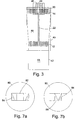
- FIG. 3 there is shown a cross-section of the apparatus in use.
- the die head 10 is sealed within a cylindrical sleeve 40 with the second plate 14 located at one end of the sleeve 40 and the first plate 12 spaced from the second plate 14 within the sleeve 40.
- a supply pipe is engaged with the first plate 12 via the support 42 such that a first material 44 can be fed to the tube 22.
- the remaining first apertures 18 are blocked by bungs so that they are not fed by the supply pipe.
- a second material 46 is fed into the sleeve 40 around the support 42 and fills the space between the first and second plates 12,14.
- the first and second materials 44, 46 are then extruded through the second apertures 20 and the shaping aperture 32 to provide an extrudate consisting of a triangular prism of the second material 46 (e.g. milk chocolate) having a thin filling of the first material 44 (e.g. white chocolate) therethough.
- a disc-shaped stainless steel plate 50 for use either as a first plate or as a second plate in an extrusion die head.
- the plate 50 comprises approximately 130 circular apertures 52 which are arranged in a series of concentric circles. Each aperture has the same size and shape.
- Each aperture has a diameter of approximately 2.1 mm and is spaced from its nearest neighbour by approximately 1 mm i.e. the ratio of the diameter of the aperture to the distance between that aperture and its nearest neighbour is approximately 2:1.
- FIG 5 there is shown a disc-shaped stainless steel second plate 60 and fastened thereto a disc-shaped stainless steel shaping plate 62.
- the second plate 62 comprises a plurality of second apertures 64, some of which are visible through a square shaping aperture 66 in the shaping plate 62.
- the extrudate produced from this apparatus will have a square cross-section and a number of spaced channels extending throughout.
- FIG 6 there is shown a disc-shaped stainless steel second plate 70 and fastened thereto a disc-shaped stainless steel shaping plate 72.
- the second plate 72 comprises a plurality of second apertures 74, some of which are visible through a shaping aperture 76 in the shaping plate 72.
- the shaping aperture 76 is a horizontal slot which extends upwardly at each end and results in an extrudate having the same cross-section with channels of a filling material extending throughout.
- a shaping plate 80 having a square shaping aperture 82 therein.
- the shaping plate 80 has two triangular cover portions 84 located within shaping plate 80 adjacent the aperture 82. In figure 7a the cover portions 84 are located away from the shaping aperture 82 such that the outline of the shaping aperture 82 is square whereas in figure 7b the cover portions 84 have been moved linearly to restrict the aperture 82 such that its outline has been changed to a triangle.
Description
- The present invention relates to an extrusion die head and apparatus comprising the extrusion die head, for the extrusion of hollow or centre-filled shapes.
-
GB 2186836 GB 2186836 -
US 3,779,676 describes a die head for extruding a striped product having veins running therethrough by bringing together two products from separate die channels together under pressure in the die head. The die has two sets of plates connected by tubes. A first product flows through the first plate, through the tubes and through the second plate. The second material flows around the tubes between the two plates and passes through additional holes in the second plate not connected to the tubes. -
US 6,086,352 describe an extruder for extruding food products that are centre filled. The extruder has a die including a plurality of tubes extending from a first pressurised product chamber inside an extrusion nozzle. The second product is introduced into the extrusion nozzle externally of and upstream of the downstream ends of the tubes so that as the first and second product flow along the extrusion nozzle they become combined as the first product exits the ends of the tubes. The die can be changed to give different centre filled effects. - It is an object of the present invention to provide an extrusion die which can be easily modified to produce a range of extruded products.
- According to a first aspect of the present invention, there is provided an extrusion die head for the preparation of a plurality of centre-filled products of varying composition as defined in claim 1. Each product comprises a first (filling) material and a second (outer) material.
- The die head comprises at least one tube such that a first material may be extruded through the tube or tubes and a second material may be extruded around the tube or tubes,
wherein the location and the number of the tubes may be customised to vary the location and amount of the first material relative to the second material and thereby vary the composition of the centre-filled product. - The customisation is achieved by means of the or each tube being detachably engaged with a first plate having a plurality of first apertures therein. A flow path is defined for the first material from the first aperture through the associated tube. By detachably engaged, it will be understood that the or each tube is not permanently fixed to the first plate. Instead, the or each tube can be removed from its position at a given first aperture and then replaced in another position at a different first aperture. In this way, a range of products may be produced using a particular first plate.
- According to a second aspect of the present invention there is provided an extrusion die apparatus comprising a sleeve enclosing the die head of the first aspect.
- According to a third aspect of the present invention there is provided an extrusion method for the preparation of a plurality of centre-filled products of varying composition as defined in claim 8. Each product comprises a first material and a second material. The method comprises co-extruding the first material through at least one tube and the second material around the tube or tubes;
wherein the location and the number of the tubes may be customised to vary the location and amount of the first material relative to the second material and thereby vary the composition of the centre-filled product. - Related to the invention, but not claimed herein is a kit for preparing the die head comprising
a first plate having a plurality of first apertures therein; and
at least one tube suitable for linking with a first aperture. - The kit may comprise a plurality of tubes suitable for linking with a plurality of first apertures. The kit may additionally comprise at least one blocking element for blocking a first aperture. Suitable blocking members include a cover (e.g. a silicone membrane) or a plug or bung.
- According to a fourth aspect of the present invention, there is provided an extrusion die head as defined in claim 2, comprising
a first plate having a plurality of first apertures therein;
a second plate spaced from the first plate and having a plurality of second apertures therein; and
at least one tube,
wherein the or each tube is detachably engaged at opposite ends to the first and second plates respectively whereby to define a flowpath between a pair of first and second apertures. - According to a fifth aspect of the present invention, there is provided an extrusion die apparatus comprising a sleeve enclosing the die head of the fourth aspect.
The second plate may be located at one end of the sleeve and the opposite end of the sleeve is engaged with a supply pipe for a second material;
and the first plate is provided at one end of a support which extends axially into the sleeve and is engaged with a supply pipe for a first material. - According to a sixth aspect of the present invention there is provided an extrusion method comprising extruding a first material and a second material using the extrusion die of the fourth aspect as defined in claim 9. The method comprises conveying a first material from a first aperture via the at least one tube to a second aperture; and
simultaneously conveying a second material directly to a second aperture;
whereby to co-extrude the first material and the second material through the second apertures. - Related to the invention, but not claimed herein is a kit for preparing the die head of the fourth aspect comprising
a first plate having a plurality of first apertures therein;
a second plate having a plurality of second apertures therein; and
at least one tube for linking a first aperture to a second aperture. - The kit may additionally comprise at least one shaping plate for fastening to the second plate and thereby blocking at least one but not all of the second apertures therein. The kit may additionally comprise a plurality of shaping plates. In this way, a variety of shapes of extruded product may be obtained using the kit.
- The kit may additionally comprise at least one blocking element for blocking a first aperture. Suitable blocking members include a cover (e.g. a silicone membrane) or a plug or bung.
- It will be understood that the die head of the fourth aspect is employed to co-extrude a first material and a second material through the second apertures. The first material is conveyed from one or more first apertures via one or more tubes to one or more second apertures where it is extruded. Simultaneously, a second material is supplied directly to the remaining second apertures (those second apertures which are not engaged with a tube) where it is extruded. Those first apertures which are not engaged with a tube may be blocked to prevent the first and second materials passing through. The blocking of the excess first apertures may be achieved individually, for example by placing a plug or bung in each of the excess first apertures. Alternatively, a cover (e.g. a silicone membrane) may be placed around the first plate to cover all of the first apertures and then the at least one tube is punched through selected first apertures.
- By detachably engaged, it will be understood that the tube can be removed from its position between a pair of first and second apertures and then replaced in another position between a different pair of first and second apertures. For example, the die head may be disassembled by separating the first and second plates and removing the tube from its position between one pair of first and second apertures and then reassembled by placing the tube in an alternative position between another pair of first and second apertures. Alternatively, the tube may be removed from the first and second plates by sliding the entire length of the tube through a first or second aperture.
- The use of a detachable tube is advantageous because the composition of the extrudate can be easily altered without the need to redesign the entire die head. By transferring the tube or tubes to different first and second apertures, the location of the first material (usually a filling material) within the second material may be modified.
- The number and arrangement of the tubes may be varied to provide a range of different patterns in the resulting extrudate. The tubes may provide a flowpath to a series of first apertures which together form a shape. Suitable shapes include a triangle, a square, a rectangle, a pentagon, a hexagon, a circle and a star.
- The cross-section of the extrudate (formed by the first and second materials) will correspond to the shape formed by all of the second apertures. For example, if the second apertures are arranged to form a circle, the resulting extrudate will have a circular cross-section. The location of the first material within the second material will vary depending on the location of the tubes but the cross-section of the extrudate will remain constant. In a particular embodiment, a shaping plate is fastened to the second plate so that the cross-section of the resulting extrudate may be modified. The shaping plate comprises at least one aperture and modifies the cross-section of the resulting extrudate by blocking at least one but not all of the second apertures. The shaping plate is typically thinner than the second plate and provides a simple, inexpensive way to modify the die head. The shaping plate may be made from a plastics material, metal or glass. The shaping plate may be fixed against relative rotation with second plate. Alternatively, the shaping plate may be rotatable relative to the second plate.
- M&C PB140672EP The second plate may comprise at least 25, at least 40, at least 60, at least 75, at least 90, at least 120 or at least 150 second apertures. In one embodiment, the number of second apertures is greater than the number of tubes.
- The number of first apertures may be equal to the number of second apertures. Alternatively, the number of first apertures may be less than the number of second apertures.
- The cross-section of each second aperture is selected depending on the desired appearance of the resulting product, for example, the cross-section of each second aperture may be circular, square or diamond. In a particular embodiment, the cross-section of each of the second apertures is circular. The cross-section of each second aperture may be the same as or different from the cross-section of any of the first apertures. In a particular embodiment, the cross-section of each second aperture is circular.
- It will be understood that the at least one tube must have a good seal with the first and second apertures to ensure successful extrusion. In one embodiment, the opposite ends of the tube are sealed within the first and second apertures respectively. In that embodiment, the exterior cross-section of the at least one tube may be the same as the cross-section of the first and/or second apertures.
- Each second aperture has a diameter. As used herein, 'diameter' is used to refer to the maximum width of the second aperture regardless of cross-sectional shape (i.e. not limited to circular cross-sections).
- The second apertures may have a diameter of less than 10mm, less than 6mm, less than 3mm, less than 2 mm, less than 1 mm, less than 0.5 mm, or less than 0.25 mm. Smaller apertures are useful since they allow for intricate patterns to be obtained. In some embodiments the apertures have a diameter of less than 100 µm, 50 µm, or 10 µm. An extrusion die having such small apertures is disclosed in International (
PCT) Application Publication No. WO 2005/056272 . The use of very small apertures allows for the incorporation of capillaries of the first material in the resulting extruded material. Such capillaries of first material are thought to be less prone to leakage through the second material than thicker channels of first material may be. In one embodiment, all of the second apertures have substantially the same size and shape such that the at least one tube may be employed to deliver the first material to any one of the second apertures i.e. the second plate comprises just one series of second apertures where each of the first apertures within the series has substantially the same size and shape as the other second apertures within that series. Alternatively, the second apertures may have a range of different sizes and shapes. It will be understood that it is more convenient if a given tube can be employed to deliver material to any one of a large number of second apertures. In a particular embodiment, the second plate comprises no more than three series of second apertures where each of the second apertures within a given series has substantially the same size and shape as the other second apertures within that series. - The second apertures are spaced apart from one another by a given distance. In a particular embodiment the ratio of the diameter of a second aperture to the shortest distance between that second aperture and its nearest neighbour is from 3:1 to 1:1 and may be approximately 2:1. This range of ratios has been found to be particularly useful for producing a cohesive extruded product.
- The second plate may be made from plastics or metal, for example stainless steel. In a particular embodiment, the second plate is made from metal. The second plate may be disc-shaped. In a particular embodiment, the first and second plates have the same shape.
- The first and second plates must remain spaced from one another in use. This may be achieved by placing connecting members between the first and second plates. The connecting members may be detachably engaged (for example, using screw fixings) with the first and/or second plates so the die head can be easily disassembled and reassembled. Alternatively the first plate can be secured to the interior surface of the sleeve so that it remains spaced from the second plate.
- According to a seventh aspect of the present invention, there is provided an extrusion die head as defined in claim 4. The extrusion die head comprises a shaping plate having a shaping aperture therein;
a first plate spaced from the shaping plate and having a plurality of first apertures therein; and
at least one tube located between the shaping plate and the first plate;
wherein the or each tube is detachably engaged at one end to the first plate whereby to define a flowpath between the first aperture and the shaping aperture. - According to an eighth aspect of the present invention, there is provided an extrusion die apparatus comprising a sleeve enclosing the die head of the seventh aspect as defined in claim 6.
The shaping plate may be located at one end of the sleeve and the opposite end of the sleeve is engaged with a supply pipe for a second material;
and the first plate is provided at one end of a support which extends axially into the sleeve and is engaged with a supply pipe for a first material. - According to a ninth aspect of the present invention there is provided an extrusion method comprising extruding a first material and a second material using the extrusion die of the seventhaspect as defined in
claim 10. The method comprises conveying a first material from a first aperture via the at least one tube to the shaping aperture; and
simultaneously conveying a second material directly to the shaping aperture; whereby to co-extrude the first material and the second material through the shaping aperture. - Related to the invention, but not claimed herein is a kit for preparing the die head of the seventh aspect comprising
a shaping plate having a shaping aperture therein;
a first plate having a plurality of first apertures therein; and
at least one tube for linking a first aperture to the shaping aperture. - The kit may additionally comprise at least one blocking element for blocking a first aperture. Suitable blocking members include a cover (e.g. a silicone membrane) or a plug or bung.
- It will be understood that the die head is employed to co-extrude a first material and a second material through the shaping aperture in the shaping plate. The first material is conveyed from one or more first apertures via one or more tubes to the shaping aperture where it is extruded. Simultaneously, the second material is supplied directly to the shaping aperture where is extruded around the tube or tubes. In some embodiments, those first apertures which are not engaged with a tube are blocked to prevent the first and second materials passing through.
- By detachably engaged, it will be understood that the tube can be removed from its position between the first aperture and the shaping aperture and then replaced in another position between a different first aperture and the spacing aperture. For example, the die head may be disassembled by separating the shaping plate and the first plate, removing the tube and then reassembled by placing the tube in an alternative position between a different first aperture and the shaping aperture. Alternatively, the tube may be removed by sliding the entire length of the tube through the shaping aperture or a first aperture.
- The use of a detachable tube is advantageous because the composition of the extrudate can be easily altered without the need to redesign the entire die head. By transferring the tube or tubes to different first apertures, the location of the first material (usually a filling material) within the second material may be modified.
- The shaping plate may be fixed against relative rotation with the first plate or the shaping plate may be rotatable relative to the first plate.
- If desired, a further plate having a plurality of apertures therein (a second plate) may be located between the shaping plate and the first plate.
- In one embodiment the die head comprises at least 10, at least 15, at least 30 or at least 60 tubes. By increasing the number of tubes, the complexity of the pattern produced by the first material may be increased. The tube may be rigid or flexible and may be made from a plastics material, metal or glass. In a particular embodiment, the tube is a hollow steel or copper rod.
- The tubes may have an inner diameter of less than 10mm, less than 6mm, less than 3mm, less than 2 mm or less than 1 mm. Smaller tube diameters are useful since they allow for intricate patterns to be obtained. In some embodiments the tube or tubes may have an inner diameter of less than 500µm, less than 250µm, less than 100 µm, less than 50 µm, or less than 10 µm. The tubes may be considered to be microcapillaries. Extrusion dies comprising needles having very small bores are disclosed in International (
PCT) Application Publication No. WO 2005/056272 andWO2008044122 . The use of very small bores allows for the incorporation of capillaries of the first material in the resulting extruded material. Such capillaries of first material are thought to be less prone to leakage through the second material than thicker channel of first material may be. - The inner diameter of the tube or tubes will affect the diameter of the channels of filling material in the extrudate. It will be understood that the extrudate can be stretched (pulled) as it exits the die head making it thinner and thereby decreasing the diameter of the filling material. For example, an extrudate made from a die head comprising a tube having an inner diameter of 3mm can be stretched such the filling material has a diameter of just 1 mm.
- In one embodiment, the number of first apertures is greater than the number of tubes.
- The first plate may comprise at least 25, at least 40, at least 60, at least 75, at least 90, at least 120 or at least 150 first apertures.
- Each first aperture has a diameter. As used herein, 'diameter' is used to refer to the maximum width of the first aperture regardless of cross-sectional shape (i.e. not limited to circular cross-sections).
- The first apertures may have a diameter of less than 10mm, less than 6mm, less than 3mm, less than 2 mm, less than 1 mm, less than 0.5 mm, or less than 0.25 mm. Smaller apertures are useful since they allow for intricate patterns to be obtained. In some embodiments the apertures have a diameter of less than 100 µm, 50 µm, or 10 µm. An extrusion die having such small apertures is disclosed in International (
PCT) Application Publication No. WO 2005/056272 . The use of very small apertures allows for the incorporation of capillaries of the first material in the resulting extruded material. Such capillaries of first material are thought to be less prone to leakage through the second material than thicker channel of first material may be. - The first apertures are spaced apart from one another by a given distance. In a particular embodiment the ratio of the diameter of a first aperture to the shortest distance between that first aperture and its nearest neighbour is from 3:1 to 1:1 and may be approximately 2:1.
- According to a tenth aspect of the present invention, there is provided an extrusion die head as defined by claim 5. The extrusion die head comprises a shaping plate having a shaping aperture therein; and a first plate spaced from the shaping plate and having a plurality of telescopic tubes attached thereto, each tube having an extended position whereby to define a flowpath through the tube to the shaping aperture and a retracted position whereby to prevent flow therethough.
- According to an eleventh aspect of the present invention, there is provided an extrusion die apparatus comprising a sleeve enclosing the die head of the tenth aspect as defined in claim 6.
The shaping plate may be located at one end of the sleeve and the opposite end of the sleeve is engaged with a supply pipe for a second material;
and the first plate is provided at one end of a support which extends axially into the sleeve and is engaged with a supply pipe for a first material. - Related to the invention but not claimed herein is an extrusion method comprising extruding a first material and a second material using the extrusion die of the tenth aspect, comprising
conveying a first material through an extended telescopic tube to the shaping aperture; and
simultaneously conveying a second material directly to the shaping aperture;
whereby to co-extrude the first material and the second material through the shaping aperture. - It will be understood that the die head is employed to co-extrude a first material and a second material through the shaping aperture in the shaping plate. The first material is conveyed from the first plate through the extended tubes to the shaping aperture where it is extruded. Simultaneously, the second material is supplied directly to the shaping aperture where it is extruded around the extended tube or tubes. By varying the number and location of the tubes that are in the extended position and those in the retracted position, the amount and location of the first material relative to the second material may be modified.
- The first plate may be made from plastics or metal, for example stainless steel. In a particular embodiment, the first plate is made from metal. The first plate may be disc-shaped.
- If desired, a plurality of supply pipes may be employed to deliver a plurality of first materials to the first plate and/or apertures.
- In one embodiment the first material is a filling material selected from a gas, liquid, gel, paste, powder or an extrudable solid. It will be understood that where a gas is used as the first material, the resulting product will have hollow portions.
- Suitable gases include non-toxic gases suitable for food use such as air, nitrogen, nitrous oxide, and carbon dioxide. Suitable liquids include oils, including fruit flavouring oils, herbal flavouring oils; alcoholic beverages, including liqueurs; syrups, including glucose syrups, high fructose corn syrups, high maltose corn syrups; and sugar-free syrups; viscous liquids such as caramels; and emulsions, including creams (oil-in-water emulsions), and water-in-oil emulsions. Suitable gels include those derived from gelatin, gum Arabic, locust bean gum, guar gum, carrageenan or alginates. Suitable pastes include almond paste, peanut paste, other nut pastes, starch-based pastes, and fruit pastes (such as purees). Suitable powders include sherbet, popping candy, and other confectionery powders. Suitable extrudable solids include chewing gum, bubble gum, candy, and chocolate (such as aerated and non-aerated forms of milk, dark or white chocolate, optionally including additional flavourings). Where the filling material is chocolate and the second material is chocolate, it will be understood that the chocolate of the filling material will typically be distinguishable from that of the second material. For example, where the second material is (non-aerated) milk chocolate, the filling material may be selected from white chocolate, dark chocolate, aerated milk chocolate, praline, or flavoured milk chocolate (such as with mint or orange flavour).
- In some embodiments, the method further comprises modifying a filling material within the product. Such modification may involve a change in physical state, such as for example solidification of a liquid; or a change in composition, such as a loss in moisture, or a chemical reaction. The modification may be caused by active treatment of the extruded product (such as maintaining the temperature of the extruded product above or below a certain level, or storing it in an atmosphere having a specific humidity level) or may happen passively as a result of the environment within the extrudate following extrusion or simply after a period of time. For example, the filling material may be an aqueous solution of gelatine, which, following cooling of the extrudate, sets into a gel.
- In one embodiment, the second material is an edible extrudable solid. Suitable edible extrudable solids include chewing gum, bubble gum, candy, and chocolate (such as aerated and non-aerated forms of milk, dark or white chocolate, optionally including additional flavourings).
- According to a twelfth aspect of the present invention there is a provided an extrusion die apparatus comprising a sleeve enclosing a die head, wherein the die head comprises a shaping plate having a shaping aperture therein and the shaping plate is detachably engaged with the sleeve.
- In prior art extrusion dies, the shaping plate is integrally formed with the rest of the apparatus such that it cannot be removed and replaced. It is therefore necessary to shut down the production line when changing from one shape of product to another. The use of a detachable shaping plate allows the shaping plate to be replaced quickly and easily such that a plurality of products having different cross-sections may be made.
- Related to the present invention is a shaping plate for an extrusion die, the shaping plate comprising a shaping aperture therein, wherein the outline of the shaping aperture may be changed.
- The shaping plate may comprise at least one cover portion which may be moved to restrict the shaping aperture and thereby change its outline. The cover portion may be located within the shaping plate and moves linearly to restrict the shaping aperture.
- The outline of the shaping aperture may be changed such that the die can be used to make products with different cross-sections without having to replace the shaping plate. This is useful to quickly swap production to different products or might even be employed during the production of a single product such that the product has a variable cross-section. Conveniently, the outline of the shaping aperture will be changed remotely to assist in the automation of the extrusion method.
- Embodiments of the invention will now be described by way of example, with reference to the following figures.
-
Figure 1 is an expanded perspective view of an apparatus comprising a die head in accordance with an embodiment of the invention. -
Figure 2 is a perspective view of the apparatus offigure 1 -
Figure 3 a cross-section of the apparatus offigure 1 . -
Figure 4 is a front view of a plate for a die head in accordance with an embodiment of the invention. -
Figure 5 is a front view of a shaping plate and second plate of accordance with another embodiment of the invention. -
Figure 6 is a front view of a shaping plate and second plate of accordance with another embodiment of the invention. -
Figures 7a and 7b are front views of a shaping plate in accordance with an embodiment of the invention. -
Figure 1 shows a stainless steel diehead 10 comprising a disc-shapedfirst plate 12 and a disc-shapedsecond plate 14 spaced apart and connected by two rigid connectingmembers 16 which have been screwed to the first andsecond plates first plate 12 and thesecond plate 14 comprise approximately 90 firstcircular apertures 18 and approximately 90 secondcircular apertures 20 respectively. Thefirst apertures 18 and thesecond apertures 20 are arranged in a pattern of concentric circles. Ahollow rod 22 links afirst aperture 18 in the centre of thefirst plate 12 and asecond aperture 20 in the centre of thesecond plate 14. Therod 20 has an inner diameter of approximately 1.8mm. Whilst just onerod 22 is shown for the sake of clarity, it will be understood that a number of rods may be employed. - A stainless
steel shaping plate 30 may be fastened to thesecond plate 14 to change the shape of resulting extrudate. The shapingplate 30 is also disc-shaped and comprises atriangular aperture 32 although the skilled reader will appreciate that any number of shapes could employed. The shapingplate 30 is thinner than the first andsecond plates product 34 has a triangular cross-section and a filling through its centre. Thedie head 10 is sealed within acylindrical sleeve 40 and thefirst plate 12 is attached to asupport 42. - Referring to
figure 2 , there is shown a perspective view of the apparatus. Thedie head 10 is sealed within thesleeve 40 and is not visible. - Referring to
figure 3 , there is shown a cross-section of the apparatus in use. Thedie head 10 is sealed within acylindrical sleeve 40 with thesecond plate 14 located at one end of thesleeve 40 and thefirst plate 12 spaced from thesecond plate 14 within thesleeve 40. A supply pipe is engaged with thefirst plate 12 via thesupport 42 such that afirst material 44 can be fed to thetube 22. The remainingfirst apertures 18 are blocked by bungs so that they are not fed by the supply pipe. Asecond material 46 is fed into thesleeve 40 around thesupport 42 and fills the space between the first andsecond plates second materials second apertures 20 and the shapingaperture 32 to provide an extrudate consisting of a triangular prism of the second material 46 (e.g. milk chocolate) having a thin filling of the first material 44 (e.g. white chocolate) therethough.
Referring tofigure 4 , there is shown a disc-shapedstainless steel plate 50 for use either as a first plate or as a second plate in an extrusion die head. Theplate 50 comprises approximately 130circular apertures 52 which are arranged in a series of concentric circles. Each aperture has the same size and shape. Each aperture has a diameter of approximately 2.1 mm and is spaced from its nearest neighbour by approximately 1 mm i.e. the ratio of the diameter of the aperture to the distance between that aperture and its nearest neighbour is approximately 2:1. - Referring to
figure 5 , there is shown a disc-shaped stainless steelsecond plate 60 and fastened thereto a disc-shaped stainlesssteel shaping plate 62. Thesecond plate 62 comprises a plurality ofsecond apertures 64, some of which are visible through asquare shaping aperture 66 in the shapingplate 62. The extrudate produced from this apparatus will have a square cross-section and a number of spaced channels extending throughout.
Referring tofigure 6 , there is shown a disc-shaped stainless steelsecond plate 70 and fastened thereto a disc-shaped stainlesssteel shaping plate 72. Thesecond plate 72 comprises a plurality ofsecond apertures 74, some of which are visible through a shapingaperture 76 in the shapingplate 72. The shapingaperture 76 is a horizontal slot which extends upwardly at each end and results in an extrudate having the same cross-section with channels of a filling material extending throughout.
Referring tofigures 7a and 7b , there is shown a shapingplate 80 having asquare shaping aperture 82 therein. The shapingplate 80 has twotriangular cover portions 84 located within shapingplate 80 adjacent theaperture 82. Infigure 7a thecover portions 84 are located away from the shapingaperture 82 such that the outline of the shapingaperture 82 is square whereas infigure 7b thecover portions 84 have been moved linearly to restrict theaperture 82 such that its outline has been changed to a triangle.
Claims (14)
- An extrusion die head (10) for the preparation of a plurality of centre-filled products of varying composition wherein each product comprises a first material and a second material,
said die head (10) comprising: at least one tube (22) such that a first material may be extruded through the tube (22) or tubes and a second material may be extruded around the tube (22) or tubes; and a first plate (12) having a plurality of first apertures (18) therein; wherein
the location and the number of the tubes (22) may be customised to vary the location and amount of the first material relative to the second material and thereby vary the composition of the centre-filled product; and
the customisation is achieved by means of the or each tube (22) being detachably engaged with the first plate (12) such that a flow path is defined for the first material from the first apertures (18) through associated at least one tube (22); and characterised in that
the number of first apertures (18) is greater than the number of tubes (22). - The die head (10) of claim 1 comprising
a second plate (14) spaced from the first plate (12) and having a plurality of second apertures (20) therein; and
wherein the or each tube (22) is detachably engaged at opposite ends to the first (12) and second (14) plates respectively whereby to define a flowpath between a pair of first (18) and second (20) apertures. - The die head (10) of claim 2, wherein a shaping plate (30) comprising at least one shaping aperture (32) is fastened to the second plate (14) thereby modifying the cross-section of the resulting extrudate (34).
- The die head (10) of claim 1 comprising
a shaping plate (30) having a shaping aperture (32) therein;
the first plate (12) being spaced from the shaping plate (30); and
wherein said at least one tube (22) is located between the shaping plate (32) and the first plate (12) so as to define a flowpath between the first aperture (18) and the shaping aperture (32). - The die head (10) of claim 1 comprising
a shaping plate (30) having a shaping aperture (32) therein; and
the first plate (12) is spaced from the shaping plate (30) and has a plurality of telescopic tubes attached thereto, each tube (22) having an extended position whereby to define a flowpath through the tube (22) to the shaping aperture (32) and a retracted position whereby to prevent flow therethough. - An extrusion die apparatus comprising a sleeve (40) enclosing the die head (10) of any one of the preceding claims.
- The apparatus of claim 6, wherein the die head (10) comprises a shaping plate (30) having a shaping aperture (32) therein and the shaping plate (30) is detachably engaged with the sleeve (40).
- An extrusion method for the preparation of a plurality of centre-filled products of varying composition wherein each product comprises a first material and a second material, the method comprising extruding the first material through at least one tube (22) attached to a first plate (12) having a plurality of first apertures (18) therein such that a flow path is defined for the first material from the first apertures (18) through the associated tube (22), and the second material around the tube (22)or tubes;
wherein the location and the number of the tubes (22) may be customised to vary the location and amount of the first material relative to the second material and thereby vary the composition of the centre-filled product;
the customisation is achieved by means of the or each tube (22) being detachably engaged with the first plate (12); and
the number of first apertures (18) is greater than the number of tubes (22). - The method of claim 8 comprising extruding a first material and a second material using the extrusion die (10) of claim 2, comprising
conveying a first material from a first aperture (18) via the at least one tube (22) to a second aperture (20); and
simultaneously conveying a second material directly to a second aperture (20); whereby to co-extrude the first material and the second material through the second apertures (20). - The method of claim 8 comprising extruding a first material and a second material using the extrusion die (10) of claim 4, comprising
conveying a first material from a first aperture (18) via the at least one tube (22) to the shaping aperture (32); and
simultaneously conveying a second material directly to the shaping aperture (32); whereby to co-extrude the first material and the second material through the shaping aperture (32). - The method of any one of claims 8 to 10, wherein the second material is an edible extrudable solid.
- The extrusion die head (10) of any one of claims 3 to 5, wherein the outline of the shaping aperture (32) may be changed.
- The extrusion die apparatus of claim 7, wherein the outline of the shaping aperture (32) may be changed.
- The method of claim 10, wherein the outline of the shaping aperture (32) may be changed.
Priority Applications (1)
| Application Number | Priority Date | Filing Date | Title |
|---|---|---|---|
| PL10725246T PL2440069T3 (en) | 2009-06-10 | 2010-06-04 | Extrusion die head |
Applications Claiming Priority (2)
| Application Number | Priority Date | Filing Date | Title |
|---|---|---|---|
| GB0909988.8A GB2470937B (en) | 2009-06-10 | 2009-06-10 | Extrusion die head |
| PCT/GB2010/001108 WO2010142941A1 (en) | 2009-06-10 | 2010-06-04 | Extrusion die head |
Publications (2)
| Publication Number | Publication Date |
|---|---|
| EP2440069A1 EP2440069A1 (en) | 2012-04-18 |
| EP2440069B1 true EP2440069B1 (en) | 2016-10-05 |
Family
ID=40937186
Family Applications (1)
| Application Number | Title | Priority Date | Filing Date |
|---|---|---|---|
| EP10725246.2A Active EP2440069B1 (en) | 2009-06-10 | 2010-06-04 | Extrusion die head |
Country Status (8)
| Country | Link |
|---|---|
| US (1) | US8899953B2 (en) |
| EP (1) | EP2440069B1 (en) |
| AU (1) | AU2010258463B2 (en) |
| BR (1) | BRPI1010730A8 (en) |
| CA (1) | CA2764923C (en) |
| GB (1) | GB2470937B (en) |
| PL (1) | PL2440069T3 (en) |
| WO (1) | WO2010142941A1 (en) |
Families Citing this family (2)
| Publication number | Priority date | Publication date | Assignee | Title |
|---|---|---|---|---|
| GB2470937B (en) | 2009-06-10 | 2014-09-24 | Cadbury Uk Ltd | Extrusion die head |
| CN104397863A (en) * | 2014-12-12 | 2015-03-11 | 四川金鼓食品有限责任公司 | Vermicelli machine and transition part thereof |
Family Cites Families (26)
| Publication number | Priority date | Publication date | Assignee | Title |
|---|---|---|---|---|
| US3227103A (en) | 1963-08-21 | 1966-01-04 | Schafer Leonhard | Spiral design pastry die |
| US3344751A (en) | 1966-11-04 | 1967-10-03 | Marigold Foods Inc | Device for making confections |
| US3408960A (en) * | 1967-06-12 | 1968-11-05 | Ho Maid Products Co | Powered variegator for frozen comestible manufacture |
| FR2110666A5 (en) * | 1970-10-26 | 1972-06-02 | Clair Bernard Savonnerie | |
| US3840311A (en) * | 1971-06-01 | 1974-10-08 | Glacier Industries | Apparatus for extruding multi-flavor ice cream products of varied shapes |
| US3793466A (en) * | 1971-06-11 | 1974-02-19 | Lever Brothers Ltd | Process for preparing a restructured meat product |
| US3836302A (en) * | 1972-03-31 | 1974-09-17 | Corning Glass Works | Face plate ring assembly for an extrusion die |
| US3947214A (en) * | 1974-12-13 | 1976-03-30 | Corning Glass Works | Extrusion die mask |
| US4480980A (en) * | 1978-11-02 | 1984-11-06 | Beehive Machinery, Inc. | Apparatus for extruding composite food products |
| JPS61135575A (en) * | 1984-10-17 | 1986-06-23 | Fujii Haruyuki | Extruder for producing fibrous food |
| GB8602950D0 (en) * | 1986-02-06 | 1986-03-12 | Cadbury Ltd | Extrusion die |
| CA1290974C (en) | 1988-06-23 | 1991-10-22 | Norman A. E. Hoy | Extruder head for making a patterned block of an ice cream product |
| JP2751097B2 (en) * | 1995-12-18 | 1998-05-18 | 芥川製菓株式会社 | Die-casting mechanism, and method of manufacturing solidified-formed article using the mold-flowing mechanism to produce a solidified formed article having a predetermined mixed pattern |
| AT1419U1 (en) | 1996-02-02 | 1997-05-26 | Unifrost Gmbh | COEXTRUSION PRODUCT |
| JP3177181B2 (en) * | 1997-03-27 | 2001-06-18 | 日本碍子株式会社 | Extrusion equipment for ceramic honeycomb structure extrusion |
| US6086352A (en) * | 1997-04-12 | 2000-07-11 | Mcfarland; Archie Rae | Apparatus for extruding products made up of composite materials |
| JPH10337765A (en) * | 1997-06-05 | 1998-12-22 | Misawa Homes Co Ltd | Mold fixing structure |
| DE19831795A1 (en) * | 1997-07-18 | 1999-07-22 | Kannegiesser Kmh Kunststofftec | Metering die for extruded plastic |
| GB9927682D0 (en) * | 1999-11-23 | 2000-01-19 | Unilever Plc | Process for the manufacture of shaped articles |
| US6663378B2 (en) * | 2001-09-27 | 2003-12-16 | Corning Incorporated | Apparatus for correcting bow in a honeycomb extrudate |
| US7648352B2 (en) * | 2001-10-29 | 2010-01-19 | Frito-Lay North America, Inc. | Apparatus for imprinting lines on direct-expanded food products having complex shapes with improved dimensional quality |
| US6755638B2 (en) * | 2001-12-05 | 2004-06-29 | Professionals Auto Parts International Co., Ltd. | Apparatus for producing continuous extrusion molding |
| US20040164464A1 (en) * | 2003-02-21 | 2004-08-26 | Lubberts Robert B. | Device and method of correcting extrudate bow |
| US20050092365A1 (en) * | 2003-10-28 | 2005-05-05 | Rawes Godfrey D. | Extrusion assembly |
| DE202007013318U1 (en) * | 2007-09-21 | 2008-01-03 | Mauser-Werke Gmbh | Device and its use for the production of plastic containers with viewing strips |
| GB2470937B (en) | 2009-06-10 | 2014-09-24 | Cadbury Uk Ltd | Extrusion die head |
-
2009
- 2009-06-10 GB GB0909988.8A patent/GB2470937B/en active Active
-
2010
- 2010-06-04 WO PCT/GB2010/001108 patent/WO2010142941A1/en active Application Filing
- 2010-06-04 US US13/377,248 patent/US8899953B2/en active Active
- 2010-06-04 EP EP10725246.2A patent/EP2440069B1/en active Active
- 2010-06-04 PL PL10725246T patent/PL2440069T3/en unknown
- 2010-06-04 BR BRPI1010730A patent/BRPI1010730A8/en not_active Application Discontinuation
- 2010-06-04 AU AU2010258463A patent/AU2010258463B2/en active Active
- 2010-06-04 CA CA2764923A patent/CA2764923C/en active Active
Non-Patent Citations (1)
| Title |
|---|
| None * |
Also Published As
| Publication number | Publication date |
|---|---|
| GB2470937B (en) | 2014-09-24 |
| PL2440069T3 (en) | 2017-08-31 |
| CA2764923C (en) | 2017-10-24 |
| WO2010142941A1 (en) | 2010-12-16 |
| US20120135122A1 (en) | 2012-05-31 |
| AU2010258463A1 (en) | 2012-01-19 |
| GB2470937A (en) | 2010-12-15 |
| BRPI1010730A2 (en) | 2015-09-15 |
| BRPI1010730A8 (en) | 2017-12-05 |
| EP2440069A1 (en) | 2012-04-18 |
| CA2764923A1 (en) | 2010-12-16 |
| US8899953B2 (en) | 2014-12-02 |
| GB0909988D0 (en) | 2009-07-22 |
| AU2010258463B2 (en) | 2014-03-06 |
Similar Documents
| Publication | Publication Date | Title |
|---|---|---|
| EP2724622B1 (en) | Apparatus and method for manufacturing products | |
| JPH1028536A (en) | Production of extruded frozen sweet and apparatus therefor | |
| RU2500173C2 (en) | Confectionary product and its production method | |
| US20130108740A1 (en) | Consumables and methods of production thereof | |
| EP2440069B1 (en) | Extrusion die head | |
| EP2549886A1 (en) | Consumables and methods of production thereof | |
| PT1439763E (en) | Extruder die with additive reservoir and method for forming multiple colored extrudates | |
| US20130171299A1 (en) | Consumables and methods of production thereof | |
| US20130115338A1 (en) | Consumables and methods of production thereof | |
| EP2665367B1 (en) | Comestible products, apparatus and methods for production thereof | |
| US20140242243A1 (en) | Apparatus, system, and method for filling a confectionary article | |
| AU2014297959B2 (en) | Method and apparatus for making a confectionery product | |
| JP2005130789A (en) | Apparatus for extruding food material and method for producing food by utilizing the same | |
| AU2014200769B2 (en) | Apparatus and method for manufacturing products |
Legal Events
| Date | Code | Title | Description |
|---|---|---|---|
| PUAI | Public reference made under article 153(3) epc to a published international application that has entered the european phase |
Free format text: ORIGINAL CODE: 0009012 |
|
| 17P | Request for examination filed |
Effective date: 20111206 |
|
| AK | Designated contracting states |
Kind code of ref document: A1 Designated state(s): AL AT BE BG CH CY CZ DE DK EE ES FI FR GB GR HR HU IE IS IT LI LT LU LV MC MK MT NL NO PL PT RO SE SI SK SM TR |
|
| DAX | Request for extension of the european patent (deleted) | ||
| 17Q | First examination report despatched |
Effective date: 20140801 |
|
| GRAP | Despatch of communication of intention to grant a patent |
Free format text: ORIGINAL CODE: EPIDOSNIGR1 |
|
| RIC1 | Information provided on ipc code assigned before grant |
Ipc: A23P 30/25 20160101ALI20160215BHEP Ipc: B29C 47/04 20060101ALI20160215BHEP Ipc: A23G 3/00 20060101ALI20160215BHEP Ipc: A23G 3/20 20060101AFI20160215BHEP Ipc: A21C 11/16 20060101ALI20160215BHEP Ipc: B29C 47/12 20060101ALI20160215BHEP |
|
| INTG | Intention to grant announced |
Effective date: 20160304 |
|
| RBV | Designated contracting states (corrected) |
Designated state(s): AL AT BE BG CH CY CZ DE DK EE ES FI FR GR HR HU IE IS IT LI LT LU LV MC MK MT NL NO PL PT RO SE SI SK SM TR |
|
| GRAJ | Information related to disapproval of communication of intention to grant by the applicant or resumption of examination proceedings by the epo deleted |
Free format text: ORIGINAL CODE: EPIDOSDIGR1 |
|
| INTC | Intention to grant announced (deleted) | ||
| GRAR | Information related to intention to grant a patent recorded |
Free format text: ORIGINAL CODE: EPIDOSNIGR71 |
|
| GRAS | Grant fee paid |
Free format text: ORIGINAL CODE: EPIDOSNIGR3 |
|
| GRAA | (expected) grant |
Free format text: ORIGINAL CODE: 0009210 |
|
| AK | Designated contracting states |
Kind code of ref document: B1 Designated state(s): AL AT BE BG CH CY CZ DE DK EE ES FI FR GR HR HU IE IS IT LI LT LU LV MC MK MT NL NO PL PT RO SE SI SK SM TR |
|
| INTG | Intention to grant announced |
Effective date: 20160826 |
|
| REG | Reference to a national code |
Ref country code: CH Ref legal event code: EP |
|
| REG | Reference to a national code |
Ref country code: AT Ref legal event code: REF Ref document number: 833780 Country of ref document: AT Kind code of ref document: T Effective date: 20161015 |
|
| REG | Reference to a national code |
Ref country code: IE Ref legal event code: FG4D |
|
| REG | Reference to a national code |
Ref country code: DE Ref legal event code: R096 Ref document number: 602010036926 Country of ref document: DE |
|
| REG | Reference to a national code |
Ref country code: NL Ref legal event code: MP Effective date: 20161005 |
|
| REG | Reference to a national code |
Ref country code: LT Ref legal event code: MG4D |
|
| PG25 | Lapsed in a contracting state [announced via postgrant information from national office to epo] |
Ref country code: LV Free format text: LAPSE BECAUSE OF FAILURE TO SUBMIT A TRANSLATION OF THE DESCRIPTION OR TO PAY THE FEE WITHIN THE PRESCRIBED TIME-LIMIT Effective date: 20161005 |
|
| REG | Reference to a national code |
Ref country code: AT Ref legal event code: MK05 Ref document number: 833780 Country of ref document: AT Kind code of ref document: T Effective date: 20161005 |
|
| PG25 | Lapsed in a contracting state [announced via postgrant information from national office to epo] |
Ref country code: GR Free format text: LAPSE BECAUSE OF FAILURE TO SUBMIT A TRANSLATION OF THE DESCRIPTION OR TO PAY THE FEE WITHIN THE PRESCRIBED TIME-LIMIT Effective date: 20170106 Ref country code: LT Free format text: LAPSE BECAUSE OF FAILURE TO SUBMIT A TRANSLATION OF THE DESCRIPTION OR TO PAY THE FEE WITHIN THE PRESCRIBED TIME-LIMIT Effective date: 20161005 Ref country code: SE Free format text: LAPSE BECAUSE OF FAILURE TO SUBMIT A TRANSLATION OF THE DESCRIPTION OR TO PAY THE FEE WITHIN THE PRESCRIBED TIME-LIMIT Effective date: 20161005 Ref country code: NO Free format text: LAPSE BECAUSE OF FAILURE TO SUBMIT A TRANSLATION OF THE DESCRIPTION OR TO PAY THE FEE WITHIN THE PRESCRIBED TIME-LIMIT Effective date: 20170105 |
|
| PG25 | Lapsed in a contracting state [announced via postgrant information from national office to epo] |
Ref country code: HR Free format text: LAPSE BECAUSE OF FAILURE TO SUBMIT A TRANSLATION OF THE DESCRIPTION OR TO PAY THE FEE WITHIN THE PRESCRIBED TIME-LIMIT Effective date: 20161005 Ref country code: IS Free format text: LAPSE BECAUSE OF FAILURE TO SUBMIT A TRANSLATION OF THE DESCRIPTION OR TO PAY THE FEE WITHIN THE PRESCRIBED TIME-LIMIT Effective date: 20170205 Ref country code: FI Free format text: LAPSE BECAUSE OF FAILURE TO SUBMIT A TRANSLATION OF THE DESCRIPTION OR TO PAY THE FEE WITHIN THE PRESCRIBED TIME-LIMIT Effective date: 20161005 Ref country code: PT Free format text: LAPSE BECAUSE OF FAILURE TO SUBMIT A TRANSLATION OF THE DESCRIPTION OR TO PAY THE FEE WITHIN THE PRESCRIBED TIME-LIMIT Effective date: 20170206 Ref country code: ES Free format text: LAPSE BECAUSE OF FAILURE TO SUBMIT A TRANSLATION OF THE DESCRIPTION OR TO PAY THE FEE WITHIN THE PRESCRIBED TIME-LIMIT Effective date: 20161005 Ref country code: NL Free format text: LAPSE BECAUSE OF FAILURE TO SUBMIT A TRANSLATION OF THE DESCRIPTION OR TO PAY THE FEE WITHIN THE PRESCRIBED TIME-LIMIT Effective date: 20161005 Ref country code: AT Free format text: LAPSE BECAUSE OF FAILURE TO SUBMIT A TRANSLATION OF THE DESCRIPTION OR TO PAY THE FEE WITHIN THE PRESCRIBED TIME-LIMIT Effective date: 20161005 Ref country code: PL Free format text: LAPSE BECAUSE OF FAILURE TO SUBMIT A TRANSLATION OF THE DESCRIPTION OR TO PAY THE FEE WITHIN THE PRESCRIBED TIME-LIMIT Effective date: 20161005 |
|
| REG | Reference to a national code |
Ref country code: FR Ref legal event code: PLFP Year of fee payment: 8 |
|
| REG | Reference to a national code |
Ref country code: DE Ref legal event code: R097 Ref document number: 602010036926 Country of ref document: DE |
|
| PG25 | Lapsed in a contracting state [announced via postgrant information from national office to epo] |
Ref country code: SK Free format text: LAPSE BECAUSE OF FAILURE TO SUBMIT A TRANSLATION OF THE DESCRIPTION OR TO PAY THE FEE WITHIN THE PRESCRIBED TIME-LIMIT Effective date: 20161005 Ref country code: CZ Free format text: LAPSE BECAUSE OF FAILURE TO SUBMIT A TRANSLATION OF THE DESCRIPTION OR TO PAY THE FEE WITHIN THE PRESCRIBED TIME-LIMIT Effective date: 20161005 Ref country code: RO Free format text: LAPSE BECAUSE OF FAILURE TO SUBMIT A TRANSLATION OF THE DESCRIPTION OR TO PAY THE FEE WITHIN THE PRESCRIBED TIME-LIMIT Effective date: 20161005 Ref country code: DK Free format text: LAPSE BECAUSE OF FAILURE TO SUBMIT A TRANSLATION OF THE DESCRIPTION OR TO PAY THE FEE WITHIN THE PRESCRIBED TIME-LIMIT Effective date: 20161005 Ref country code: EE Free format text: LAPSE BECAUSE OF FAILURE TO SUBMIT A TRANSLATION OF THE DESCRIPTION OR TO PAY THE FEE WITHIN THE PRESCRIBED TIME-LIMIT Effective date: 20161005 |
|
| PLBE | No opposition filed within time limit |
Free format text: ORIGINAL CODE: 0009261 |
|
| STAA | Information on the status of an ep patent application or granted ep patent |
Free format text: STATUS: NO OPPOSITION FILED WITHIN TIME LIMIT |
|
| PG25 | Lapsed in a contracting state [announced via postgrant information from national office to epo] |
Ref country code: BG Free format text: LAPSE BECAUSE OF FAILURE TO SUBMIT A TRANSLATION OF THE DESCRIPTION OR TO PAY THE FEE WITHIN THE PRESCRIBED TIME-LIMIT Effective date: 20170105 Ref country code: SM Free format text: LAPSE BECAUSE OF FAILURE TO SUBMIT A TRANSLATION OF THE DESCRIPTION OR TO PAY THE FEE WITHIN THE PRESCRIBED TIME-LIMIT Effective date: 20161005 |
|
| 26N | No opposition filed |
Effective date: 20170706 |
|
| PG25 | Lapsed in a contracting state [announced via postgrant information from national office to epo] |
Ref country code: SI Free format text: LAPSE BECAUSE OF FAILURE TO SUBMIT A TRANSLATION OF THE DESCRIPTION OR TO PAY THE FEE WITHIN THE PRESCRIBED TIME-LIMIT Effective date: 20161005 |
|
| PG25 | Lapsed in a contracting state [announced via postgrant information from national office to epo] |
Ref country code: MC Free format text: LAPSE BECAUSE OF FAILURE TO SUBMIT A TRANSLATION OF THE DESCRIPTION OR TO PAY THE FEE WITHIN THE PRESCRIBED TIME-LIMIT Effective date: 20161005 |
|
| REG | Reference to a national code |
Ref country code: IE Ref legal event code: MM4A |
|
| PG25 | Lapsed in a contracting state [announced via postgrant information from national office to epo] |
Ref country code: IE Free format text: LAPSE BECAUSE OF NON-PAYMENT OF DUE FEES Effective date: 20170604 Ref country code: LU Free format text: LAPSE BECAUSE OF NON-PAYMENT OF DUE FEES Effective date: 20170604 |
|
| REG | Reference to a national code |
Ref country code: FR Ref legal event code: PLFP Year of fee payment: 9 |
|
| PG25 | Lapsed in a contracting state [announced via postgrant information from national office to epo] |
Ref country code: MT Free format text: LAPSE BECAUSE OF NON-PAYMENT OF DUE FEES Effective date: 20170604 |
|
| PG25 | Lapsed in a contracting state [announced via postgrant information from national office to epo] |
Ref country code: HU Free format text: LAPSE BECAUSE OF FAILURE TO SUBMIT A TRANSLATION OF THE DESCRIPTION OR TO PAY THE FEE WITHIN THE PRESCRIBED TIME-LIMIT; INVALID AB INITIO Effective date: 20100604 |
|
| PG25 | Lapsed in a contracting state [announced via postgrant information from national office to epo] |
Ref country code: CY Free format text: LAPSE BECAUSE OF NON-PAYMENT OF DUE FEES Effective date: 20161005 |
|
| PG25 | Lapsed in a contracting state [announced via postgrant information from national office to epo] |
Ref country code: MK Free format text: LAPSE BECAUSE OF FAILURE TO SUBMIT A TRANSLATION OF THE DESCRIPTION OR TO PAY THE FEE WITHIN THE PRESCRIBED TIME-LIMIT Effective date: 20161005 |
|
| PG25 | Lapsed in a contracting state [announced via postgrant information from national office to epo] |
Ref country code: TR Free format text: LAPSE BECAUSE OF FAILURE TO SUBMIT A TRANSLATION OF THE DESCRIPTION OR TO PAY THE FEE WITHIN THE PRESCRIBED TIME-LIMIT Effective date: 20161005 |
|
| PG25 | Lapsed in a contracting state [announced via postgrant information from national office to epo] |
Ref country code: AL Free format text: LAPSE BECAUSE OF FAILURE TO SUBMIT A TRANSLATION OF THE DESCRIPTION OR TO PAY THE FEE WITHIN THE PRESCRIBED TIME-LIMIT Effective date: 20161005 |
|
| REG | Reference to a national code |
Ref country code: FR Ref legal event code: PLFP Year of fee payment: 13 |
|
| P01 | Opt-out of the competence of the unified patent court (upc) registered |
Effective date: 20230323 |
|
| PGFP | Annual fee paid to national office [announced via postgrant information from national office to epo] |
Ref country code: FR Payment date: 20230626 Year of fee payment: 14 Ref country code: DE Payment date: 20230626 Year of fee payment: 14 |
|
| PGFP | Annual fee paid to national office [announced via postgrant information from national office to epo] |
Ref country code: PL Payment date: 20230518 Year of fee payment: 14 |
|
| PGFP | Annual fee paid to national office [announced via postgrant information from national office to epo] |
Ref country code: BE Payment date: 20230627 Year of fee payment: 14 |
|
| PGFP | Annual fee paid to national office [announced via postgrant information from national office to epo] |
Ref country code: IT Payment date: 20230620 Year of fee payment: 14 Ref country code: CH Payment date: 20230702 Year of fee payment: 14 |