EP2439902A2 - Procédé et agencement d'émission et de réception contraignantes de communications électroniques confidentielles - Google Patents
Procédé et agencement d'émission et de réception contraignantes de communications électroniques confidentielles Download PDFInfo
- Publication number
- EP2439902A2 EP2439902A2 EP11184359A EP11184359A EP2439902A2 EP 2439902 A2 EP2439902 A2 EP 2439902A2 EP 11184359 A EP11184359 A EP 11184359A EP 11184359 A EP11184359 A EP 11184359A EP 2439902 A2 EP2439902 A2 EP 2439902A2
- Authority
- EP
- European Patent Office
- Prior art keywords
- terminal
- security module
- provider
- electronic message
- message
- Prior art date
- Legal status (The legal status is an assumption and is not a legal conclusion. Google has not performed a legal analysis and makes no representation as to the accuracy of the status listed.)
- Withdrawn
Links
- 230000005540 biological transmission Effects 0.000 title claims abstract description 65
- 238000000034 method Methods 0.000 title claims abstract description 26
- 238000004891 communication Methods 0.000 claims description 22
- 238000012545 processing Methods 0.000 claims description 20
- 238000007726 management method Methods 0.000 claims description 7
- 238000012795 verification Methods 0.000 claims description 7
- 238000012384 transportation and delivery Methods 0.000 claims description 4
- 238000012790 confirmation Methods 0.000 claims description 3
- 230000004044 response Effects 0.000 claims 1
- 230000006870 function Effects 0.000 description 7
- 238000012546 transfer Methods 0.000 description 7
- 238000010586 diagram Methods 0.000 description 6
- 238000013459 approach Methods 0.000 description 2
- 239000008186 active pharmaceutical agent Substances 0.000 description 1
- 230000002457 bidirectional effect Effects 0.000 description 1
- 239000003795 chemical substances by application Substances 0.000 description 1
- 239000002131 composite material Substances 0.000 description 1
- 238000010276 construction Methods 0.000 description 1
- 230000006378 damage Effects 0.000 description 1
- 238000012217 deletion Methods 0.000 description 1
- 230000037430 deletion Effects 0.000 description 1
- 230000001419 dependent effect Effects 0.000 description 1
- 238000011161 development Methods 0.000 description 1
- 230000018109 developmental process Effects 0.000 description 1
- 238000012544 monitoring process Methods 0.000 description 1
- ORQBXQOJMQIAOY-UHFFFAOYSA-N nobelium Chemical compound [No] ORQBXQOJMQIAOY-UHFFFAOYSA-N 0.000 description 1
- 230000002093 peripheral effect Effects 0.000 description 1
- 239000007787 solid Substances 0.000 description 1
Images


Classifications
-
- H—ELECTRICITY
- H04—ELECTRIC COMMUNICATION TECHNIQUE
- H04L—TRANSMISSION OF DIGITAL INFORMATION, e.g. TELEGRAPHIC COMMUNICATION
- H04L63/00—Network architectures or network communication protocols for network security
- H04L63/12—Applying verification of the received information
-
- H—ELECTRICITY
- H04—ELECTRIC COMMUNICATION TECHNIQUE
- H04L—TRANSMISSION OF DIGITAL INFORMATION, e.g. TELEGRAPHIC COMMUNICATION
- H04L41/00—Arrangements for maintenance, administration or management of data switching networks, e.g. of packet switching networks
- H04L41/02—Standardisation; Integration
- H04L41/0246—Exchanging or transporting network management information using the Internet; Embedding network management web servers in network elements; Web-services-based protocols
- H04L41/0273—Exchanging or transporting network management information using the Internet; Embedding network management web servers in network elements; Web-services-based protocols using web services for network management, e.g. simple object access protocol [SOAP]
- H04L41/0293—Exchanging or transporting network management information using the Internet; Embedding network management web servers in network elements; Web-services-based protocols using web services for network management, e.g. simple object access protocol [SOAP] for accessing web services by means of a binding identification of the management service or element
-
- H—ELECTRICITY
- H04—ELECTRIC COMMUNICATION TECHNIQUE
- H04L—TRANSMISSION OF DIGITAL INFORMATION, e.g. TELEGRAPHIC COMMUNICATION
- H04L63/00—Network architectures or network communication protocols for network security
- H04L63/04—Network architectures or network communication protocols for network security for providing a confidential data exchange among entities communicating through data packet networks
- H04L63/0428—Network architectures or network communication protocols for network security for providing a confidential data exchange among entities communicating through data packet networks wherein the data content is protected, e.g. by encrypting or encapsulating the payload
-
- H—ELECTRICITY
- H04—ELECTRIC COMMUNICATION TECHNIQUE
- H04L—TRANSMISSION OF DIGITAL INFORMATION, e.g. TELEGRAPHIC COMMUNICATION
- H04L9/00—Cryptographic mechanisms or cryptographic arrangements for secret or secure communications; Network security protocols
- H04L9/32—Cryptographic mechanisms or cryptographic arrangements for secret or secure communications; Network security protocols including means for verifying the identity or authority of a user of the system or for message authentication, e.g. authorization, entity authentication, data integrity or data verification, non-repudiation, key authentication or verification of credentials
Definitions
- the invention relates to a method and an arrangement for securely transmitting at least one electronic message from a first terminal of a first user (sender) to at least one second terminal of a second user (receiver).
- the E-POST system of Deutsche Post AG and the DE-Mail system are known, which are each to enable the legally compliant and confidential exchange of electronic documents between citizens, authorities and companies via the Internet.
- the main objective of these systems is to make deliveries via the Internet legally secure.
- the data transmission between the Internet service provider of the sender and the Internet service provider of the recipient is encrypted.
- at least the provider (s) themselves may have unauthorized access to the electronic message data if the administrator's rights are used accordingly.
- the object of the invention is to ensure secure transmission of an electronic message from a first terminal of a first user to at least a second terminal of a second user using an infrastructure for legally binding transmission of electronic messages without having to trust the operator of this infrastructure that he neither spied nor modified the sent message content.
- the method according to the invention with the features of claim 1 and the arrangement with the features of the further independent claim ensures that cryptographic processing of the data of the electronic message takes place with the aid of the security modules provided on the transmitter side and receiver side, so that an end device can easily be terminated. to end encryption of the message between the first terminal and the second terminal is possible.
- the first user is preferably the sender and the second user is the recipient.
- the first security module is connected to the first terminal via a first data transmission connection and / or the second security module and the second terminal via a second data transmission connection.
- the first data transmission connection and / or the second data transmission connection can be formed in particular by a transmission channel in a network, preferably as a transmission channel in a wireless network.
- the first data transmission connection can be provided by a bus system of the first terminal and / or by a standardized application interface.
- the second data transmission connection can be provided by a bus system of the second terminal and / or by a standardized application interface.
- the application interfaces may be provided by software and are also referred to as APIs.
- an internal bus system of the first terminal such as a PCI bus, a PCI express bus, an ISA bus, a universal serial bus or a suitable other data bus can be used as the bus system.
- connection possibilities between the security module and the terminal various types of security module can be provided, in particular as a separate terminal, as a unit of the terminal or as processed by the terminal software module.
- the electronic message using the infrastructure for legally binding transfer transmitted electronic messages from the first terminal to a provider and transmit the message from the provider to the second terminal.
- the electronic message transmitted from the first terminal to the provider can be encrypted by the provider.
- This provider is a first provider.
- the encrypted electronic message can then be transmitted from the first provider to a second provider.
- the message is decrypted by the second provider and transmitted to the second terminal.
- an encryption of the electronic message according to the infrastructure for the legally binding transmission of electronic messages takes place during their transmission between two providers.
- This infrastructure will ensure that the requirements for legally binding electronic communications can be easily met.
- this data processing unit can provide a user management service for registering the users whose user identity is stored in the first and / or the second security module.
- an identification service for identifying a user registered in the security module is provided by the first security module and / or by the second security module, wherein the user uses a user login, such as user name and password, a user login with the help of biometric data of the user using a biometric sensor be detected, a security module connected via the Internet and / or via a wireless data transmission connection, and / or a smart card is identified.
- a simple identification of the user by the security module is possible.
- After an identification of the user and authentication of the user, in particular user information stored in the security module can be used to identify the user in components of the infrastructure for the legally binding transmission of electronic messages.
- simple and secure identification and authentication of the user is possible both in the security module and in the infrastructure for transmitting electronic messages.
- a mobile transaction number transmitted from the infrastructure for legally binding transmission of electronic messages to the e-postage provider and from there to the security module may be identified, the first terminal is sent a request to transmit the mobile transaction number to the infrastructure and wherein a transaction number is generated by a data processing unit of the infrastructure and transmitted to the e-postage provider and from there to the security module of the user's terminal.
- the transmission of the mobile transaction number from the Internet Service Provider to the E-Postage Provider takes place either by cable or via a radio network (eg GSM, GPRS, UMTS), the E-Postage Provider for the first and the second user (A), (B) each one own User account holds.
- a radio network eg GSM, GPRS, UMTS
- the information can be transmitted either on a wired path (eg Internet) or through a radio network (eg GSM, GPRS, UMTS).
- the electronic message is transmitted via a secure data connection to the provider, wherein the secure data connection between the respective terminal and the provider is established.
- the first terminal then preferably checks the cryptographically secured identity of the provider. This check preferably takes place with the aid of a cryptographic certificate available to the first terminal.
- This certificate is preferably stored in a memory area of the first security module. Using a cryptographic certificate prevents easy manipulation of the certificate. Such a certificate must only be renewed every one to five years, preferably every three years, if high safety standards are adhered to.
- the security module By using the certificate, it can be checked by the security module whether the secured data connection is actually established to the desired provider or if the destination address of the provider has been tampered with and another unwanted subscriber replaces the provider, without checking the identity of the provider a secure data connection would be established. This prevents the secure data connection from being redirected to an unwanted user. This can increase the security of the data transmission and prevent manipulation of the electronic message and unauthorized access to the electronic message.
- the respective terminal is then identified with the help of this information at the provider.
- the first terminal at the first security module request information about its secure identity
- the first security module transmits this information to the first terminal.
- the second terminal at the second security module request information about the secure identity of the second security module, which is then transmitted from the second security module to the second terminal.
- multiple secure identities may be stored in the security module for multiple users, which may then be read out of the security module and transmitted to the respective terminal connected to the security module in a user login of a user for whom information about his secure identity is stored in the security module.
- the terminal can then use this information associated with the user to identify the terminal and / or the user at the provider.
- a simpler and more secure identification of the user and / or the terminal at the provider is possible.
- a first user registered in the first security module is preferably a legal entity.
- a second user registered in the first security module is a natural person who, after registering at the first terminal and / or at the first security module, can legally send a message on behalf of the first user. Additionally, the second user may receive messages for the first user, wherein the security module then decrypts encrypted electronic communications and / or verifies signed electronic communications.
- an account information is stored at least in the first security module.
- This account information includes access to an account storage element that is assigned in particular to a user and / or the security module. From a value stored in the account storage element, a preset amount is then deducted when an electronic message is encrypted by the first security module, which is then sent using the first terminal and transmitted to the second terminal using the infrastructure.
- the first security module and / or a central processing unit may then, after deducting the amount from the stored value, additionally or alternatively send release information to the provider that is required for the provider to forward the message to the recipient.
- the release information sent to the provider may include payment information, from which the provider, depending on the provider, forwards the electronic message. This ensures that a simple payment of the fees required by the provider for the handling of the electronic message to be sent and the fees required for encrypting and / or signing according to the invention can be paid. In particular, no further operating steps of the user are required for this purpose.
- a private key of the recipient for encrypting the electronic message and / or a signature key for signing the electronic message is stored in a memory area of the first security module and / or in a memory area of a central data processing unit. From the central data processing unit, the key of the recipient for encrypting the electronic message and / or the signature key can be read out. This or these keys are used by the security module to encrypt or sign the message. This makes a simple key management in the security module itself and / or in the central data processing unit possible.
- the first security module and / or the second security module is a component integrated in the terminal.
- This component is preferably via a data bus with others Components of the first and second terminal connected.
- the security module may be provided by software executed by the terminal. As a result, two advantageous options for providing the security module are given.
- information between the respective security module and a provider which provides at least part of the infrastructure for legally binding transmission of legally binding electronic messages, can be transmitted via the respective terminal.
- no direct data transmission between the security module and the provider is possible.
- additional protection of the security module is achieved because no direct external access to the security module is possible.
- only a data exchange according to a preset protocol is possible between the security module and the respective terminal, which only provides certain instructions and data exchange steps required for the secure transmission of legally binding electronic messages, so that manipulation of the security module is effectively prevented.
- each service provider is considered, which determines the transmission of data at least on a leg between the first terminal and the second terminal.
- providers are in particular Internet service providers, e-mail providers and / or telecommunications service providers. In particular, these providers provide services and / or infrastructure for the legally binding transmission of messages.
- FIG. 1 a block diagram of an arrangement 10 for secure legally binding transfer of e-mail messages between a first end user system 12 of a user A and a second end user system 14 of a user B shown.
- a national and / or international infrastructure for legally binding e-mails is shown schematically as block 16, wherein the services required for this infrastructure 16 are provided by various data processing units, in particular by Internet service providers 18, 20 and / or others via the Internet 22 contactable data processing systems.
- the end user systems 12, 14 are connected via data transmission links 50, 80 to a so-called Electronic Postage Provider (EPP) 24.
- EPP Electronic Postage Provider
- Electronic Postage Provider 24 provides services that enable and support the secure transmission of legally binding electronic communications, such as e-mail messages.
- the electronic postage provider 24 is connected via a data transfer path 51 arranged by the arrow to further data processing units (not shown) of the infrastructure 16.
- the communication between the end user system 12 and the electronic postage provider 24 can take place, in particular, via the same data line or the same Internet connection of the respective end user system 12 as the connection to the Internet service provider 18, 20.
- the end user system 12 comprises a personal computer 26, which is used as the terminal for creating E. Mail messages, used to send these e-mail messages after creating and receiving e-mail messages.
- the personal computer 26 In conjunction with the Internet service provider 18 and the further infrastructure 16, it is possible with the help of the personal computer 26 to transmit legally binding e-mail messages to at least one other end user system 14 and receive from the other end user system 14 sent legally binding e-mail messages.
- the end user system 12 comprises a security module 28 which is connected to the personal computer 26 via at least one interface 34 and which is arranged in a postage meter machine in the present exemplary embodiment.
- data can be exchanged via the data transmission links 51 and 50, and in particular data with access information and / or authentication information from a service of the infrastructure 16 are transmitted to the security module 28 via a secure channel.
- a radio network connection such as WLAN, GSM, UMTS, may also be used for the wired transmission link 50.
- the security module 28 itself would be equipped with an antenna and a radio network controller.
- a data connection can be established between the personal computer 26 and the Internet service provider 18 via a data transmission link 27, via which access of the personal computer 26 to the e-mail services of the Internet service provider 18 and to the Internet 22 is possible.
- Authoritative e-mail messages to be sent by the personal computer 26 and legally binding e-mail messages to be received by the personal computer 26 are preferably transmitted between the personal computer 26 and the Internet service provider 18 via the data link 27 by means of a secure data connection.
- the second end user system 14 comprises a personal computer 40 as a second terminal of the arrangement 10 and a security module 44 connected to the personal computer 40 via a data interface 42, which, like the security module 28, is arranged in a franking machine.
- a data interface 42 which, like the security module 28, is arranged in a franking machine.
- data can be exchanged via the data transmission links 51 and 80 and in particular data with access information and / or authentication information can be transmitted from a service of the infrastructure 16 to the security module 44.
- a radio network connection such as WLAN, UMTS, GSM, may also be used.
- the security module would be 28 itself equipped with an antenna and a wireless network controller.
- the personal computer 26 transmits an authentication request via the data connection 27 to the Internet service provider 18, which sends them to an authentication service of the infrastructure 16 forwards.
- the infrastructure 16 generates a transaction number and transmits this transaction number via the data transmission links 51 and 50 to the security module 28.
- the security module 28 passes this transaction number via the interface 34 to the personal computer 26 and thus registers the user.
- the user can log on to the security module 38 by detecting a biometric characteristic of the user with the aid of a biometric sensor.
- an authentication of the user by a read from a smart card signature can be done, which is read by means of a reading unit after entering the smart card by the user A from the smart card and then used to authenticate the user.
- the chip card can be read by a reading unit of the personal computer 26 or by means of a reading unit of the security module 28.
- a communication link 50 is provided between the personal computer 26 and the electronic postage provider 24.
- the data transmission link 50 may be provided, for example, by a secure data transmission connection via the Internet 22.
- the security module is registered at the Electronic Postage Provider. This registration is repeated for each new user A, B to be registered on the security module 28.
- the identity of the security module 28 is checked via the data transmission channel 50 before an electronic transaction, ie before each encryption and / or signing of an e-mail to be sent and before decryption and / or verification of the signature of a received e-mail.
- the credit account of the security module 28 may be charged via the data link 50 when the electronic postage provider 24 receives a payment for the user A top for the security module via a bank interface 52 from a bank 54.
- the electronic postage provider 24 preferably has at least two data processing units, a first data processing unit 56 for managing users and their public keys for encrypting messages and, if necessary, signature keys and at least one second data processing unit 58 for fee management and credit accounts of the users A, B or
- additional administrative transactions such as locking and unlocking the security module 28, loading rate tables with fees for possible transactions, etc., may be automatically performed.
- the construction of the secure data transmission connection via the data transmission channel 50 takes place, for example, by a bidirectional hardware key management based on the Diffie-Hellmann method.
- the security module 28 can check the identity of the electronic postage provider 24. As already mentioned, this can be stored in the security module 28 and preferably only readable root certificates respectively.
- the electronic postage provider 24 can check the identity of the security module 28, in particular with the aid of a key of the security module 28 stored in a database of the electronic postage provider 24. For this purpose, several keys can be stored in a key directory, which is accessed using a Lightweight Directory Access Protocol (LDAP) (LDAP key directory).
- LDAP key directory Lightweight Directory Access Protocol
- the sender will preferably use a fresh, secret message key to encrypt and thereby implicitly authenticate the message to be sent.
- the sender used sends the used secret message key directly, for example as SMS text, to the recipient who enters it in his software security module.
- the Internet service provider 18 has at least two data processing units, in particular a security server 60 and a billing server 62 for settling end-charges, which are levied when handling legally binding e-mail messages. These are charges that the respective end user A, B has to pay when sending a legally binding e-mail message, as well as charges that the service providers 18, 20 charge each other when sending legally binding e-mail messages.
- the billing server 62 also has a bank interface 64 through which data can be exchanged between the billing server 62 and the bank 54 or another bank.
- the second Internet service provider 20 has in the same way as the first Internet service provider 18, a security server 66 and a billing server 68.
- the billing server 68 is connected via a bank interface 70 to the bank 54, via which data, in particular with payment information, is exchangeable.
- the Internet service providers 18, 20 receive via the bank interfaces 64, 70 and the electronic postage provider 24 receives information about incoming payments for user accounts of the users A and / or B via the bank interface 52.
- the billing servers 62, 68 of the Internet service providers 18, 20 each have one Data link 72, 74 connected to the billing servers 60, 68, so that information about payments received and / or payments for the user accounts of the user A, B also between the billing server 58 of the electronic postal service provider 24 and the billing servers 62, 68 of the Internet service provider 18, 20 transferable are.
- the Internet service providers 18, 20 are also connected via a respective data transmission link 76, 78 with other services of the infrastructure 16 for legally binding e-mail messages. With the help of these services, in particular a secure data exchange between the Internet service providers 18, 20 is possible, so that a retrieval of secure identification information from end users A, B is possible. Further, the services of the infrastructure may provide an end user registration service.
- the servers 60, 62 of the first Internet service provider 18, the servers 66, 68 of the second Internet service provider 20 and the data processing units 56, 58 of the electronic postal service provider 24 are each interconnected via suitable communication links, such as an internal network.
- the electronic postage provider 24 receives billing information for the respective end user A, B from the Internet service providers 18, 20.
- the electronic postage provider 24 instructs the bank 54 via the bank interface 64 to credit the invoice amount of the billing information to an account of the Internet service provider 18, 20.
- the bank 54 transmits corresponding payment information via the data transmission channels 64, 70 to the respective Internet service provider 18, 20.
- the electronic postal service provider 24 receives a notification about a payment of end users A, B to their credit accounts. The corresponding credits are then available to the customers in the form of electronic postage for download to their security module 28, 44 via the data transmission link 50, 80.
- the communication between the components 40, 44, 46 of the second end user system 14 with each other and with the second Internet service provider and the Electronic Postage Provider 24 takes place in the same way as for the components 26, 28, 30, the first Internet service provider 18 and the Electronic Postage Provider 24 described.
- the personal computer 26 serves as an intermediary between the security module 28 and the Internet service provider 18, so that no direct connection, in particular no online connection between the security module 28 and the security server 60 of the Internet service provider 18 can be produced.
- Between the Electronic Postage Provider 24 and each Internet service provider 18, 20 is a manually secured transmission of an Electronic Postage Providers Verification Key. With the help of this key, the respective Internet service provider 18, 20 then verifies the certificate chains of all security modules 28, 42.
- the registration of a new user C by an internet service provider 18 may be performed as explained below.
- the personal computer requests an ID of the security module 28 at the security module 28.
- the security module 28 then broadcasts its ID with a plurality of certificates, the first certificate including the identity of the security module 24, a time stamp, user data such as company, address, contact and, if used, a mobile transaction number signed by the security module.
- Another certificate may be a public key certificate of the security module 28, which has been previously certified by the Electronic Postage Provider 24.
- the personal computer 26 forwards the ID of the security module 28 along with the certificates to the Internet service provider 18.
- the personal computer 26 acted as a relay between the security module 28 and the Internet service provider 18, so that no online connection between the security module 28 and the security server 60 of the Internet service provider 18 is required.
- another data transfer protocol is used to transfer data between the Internet service provider 18 and the personal computer 60 rather than for data transfer between the personal computer 26 and the security module 28.
- the Internet service provider 18 checks the ID of the security module 28 for validity, the timestamp for timeliness and checks the transmitted certificates using the public key of the Electronic Postage Provider 24. If these checks are successful, the Internet service provider 18 registers the user C and stores identity characteristics of the User C in conjunction with the security module 28, in particular in conjunction with the ID of the security module 28. This registers a user C with the Internet Service Provider for legally binding e-mail and subsequently logs on to the ISP via the communication channel 27 for sending and receiving legally binding e-mails, as described for user A below ,
- the user A is logged on the personal computer 26 at the Internet service provider 18 and the electronic postage provider 24.
- a request for a mobile transaction number on the Data transmission channel 27 are transmitted to the Internet service provider 18, which then forwards this arrangement over the data transmission channel 76 to a corresponding service of the infrastructure 16.
- the mobile transaction number is then generated by this service and transmitted to the security module 28.
- the transaction number is preferably transmitted to the security module 28 with the aid of the short message service.
- the data of the e-mail message to be sent including any attachments are transmitted from the personal computer 26 to the security module 28.
- a recipient ID and / or other information about the recipient is transmitted from the personal computer 26 to the security module 28. Furthermore, information is transmitted as to whether the message content should be signed by means of a publicly verifiable signature. Furthermore, the information can be transmitted from the personal computer to the security module 28 as to whether a separate time stamp is required for the message to be sent.
- a public key of the recipient is read from a storage area of the security module 28 and / or by the security module 28 via the personal computer 26 at the electronic Postage Provider 24 requested. Upon request of the public key at the electronic postage provider 24 this is read out of the key server 56 and is transmitted to the security module 28 in the personal computer 26.
- the security module 28 checks whether sufficient credit is available for the user A for the selected charging mode in order to pay the fees incurred. If this is not the case, a corresponding error message is transmitted from the security module 28 to the personal computer 26. If one is requested for the message in individual timestamps, it will be appended to the message.
- the message content is signed with a secret key and then the message, including the signature, is encrypted using the recipient's public key.
- the encrypted message can be prefixed with the sender ID.
- the sender ID is preferably the ID of the security module 28. Alternatively or additionally, the user ID of the user A may also be added.
- the fee to be paid for the encryption and / or signature service of the security module 28 is deducted in the security module 28 from a credit stored in an account storage element.
- the encrypted and / or signed message is transmitted from the security module 28 to the personal computer 26.
- the security module after encrypting and / or signing the message, assembles a properly formatted email containing the message protected between the end user systems 12, 14.
- the user is identified by biometric data and / or by a storage element such as a user identifier using the received mobile transaction number or an alternative identifier, such as user name and password login Chip card, read or generated by an algorithm certificate, registered with the Internet service provider 18.
- the e-mail message may be transmitted via the communications channel 27 from the personal computer 26 to the Internet service provider 18, which then forwards the same to the end user system of the recipient 14.
- the e-mail message is transmitted from the first Internet service provider 18 via the Internet 22 to the second Internet service provider 20 and from there a user login via the end user system 14 transmitted to this.
- a mobile transaction number of a responsible service of the infrastructure 16 is requested, which is transmitted to the security module 44.
- the user is preferably registered with the Internet provider 20 when the mobile transaction number has already been requested, such as user name.
- other identification features can be used.
- the personal computer 40 retrieves the e-mail message stored at the internet service provider 20 so that the data of the e-mail message is transmitted from the internet service provider 20 to the personal computer 40.
- the encrypted and / or signed e-mail message is transmitted from the personal computer 40 to the security module 44.
- the security module 44 determines the recipient ID from the sent e-mail message and determines the private key stored in the security module 44 for the recipient ID and decrypts the e-mail message using the private key.
- the message content is checked using a signature verification key of the sender, which is preferably attached to the message or is obtained from the public-key directory of the electronic postal service provider 24.
- the public key of the sender is used to check this public signature.
- the decrypted message content is provided with the additional information as to whether an optional signature check or an integrity check was successful. If the message includes a timestamp, it will be added to the decrypted message.
- the decrypted message and possibly the additional information are transmitted from the security module 44 to the personal computer 40.
- the personal computer 40 processes the additional information transmitted from the security module 44 to the personal computer 40 together with the decrypted message and composes a correctly formatted e-mail message from the decrypted message content, which is then available in the personal computer 40.
- the content of the e-mail message can then be output in particular via a display unit of the personal computer 40.
- the additional information such as the successful signature verification and a time stamp, can be displayed to the recipient B in addition to the message content.
- the end user systems 12 and 14 are connected to their respective Internet service provider 18, 20 as well as to the central electronic postage provider 24 via similar data communication channels and interfaces, the end user systems 12, 14 and the other components of the device 10 being designed such that both secure and secure legally binding e-mail messages may be transmitted from the end user system 12 to the end user system 14 as well as from the end user system 14 to the end user system 12.
- the sending of e-mails from the end user system 14 may be the same as for the end user system 12 described.
- the reception of the e-mail messages by means of the end user system 12 takes place in the same way as described for the end user system 14.
- biometric user A data may be acquired and transmitted to Internet service provider 18 using a biometric sensor of the end user system 12, which compares the transmitted data with stored biometric reference patterns.
- a user logged on to the security module 24 may use the user identity of a third user C to send and receive secure legally binding e-mails, if authorized by an administrator. This is particularly advantageous if the third user C is a legal person, such as a company. Thus, an identification of a user can be performed on behalf of a third party.
- a user identity of the third user C is stored in the security module 28 and can be used by each user A of the personal computer 26 registered in the security module 28 and authorized to send messages to the third user C or to receive messages from the third user C.
- a user identity verification system may include a transaction number generator that generates a deterministic sequence of pseudo-random transaction numbers using a trap-door one-way function using a secret key; whose public counterpart is deposited during the registration of the security module 28 with the Internet service provider 18 for checking the transaction numbers.
- the PINs, the secret key and the program for calculating the trap-door one-way function are stored in a non-volatile memory of the security module 28.
- the trap-door one-way function takes into account not only the last used transaction number but also specific order data, eg As a hash value, the message to be transmitted.
- the Internet service provider 18 checks for each incoming transaction number on the basis of the previous transaction number and the current order data and the public key of the security module 28, if the current transaction number is valid. Such an approach is particularly useful when deploying security module 28 in enterprises where multiple company employees are permitted to access security module 28.
- a time limit for the validity of the identity features of one or all users by the security module 28 and / or the Internet service provider 18 may be provided.
- the validity of an end user's identity features may be limited to a preset number of checks.
- FIG. 2 shows a block diagram with the used by the terminal system 12 of the user A physical data transmission connections over which in connection with FIG. 1 constructed described data transmission channels and provided the described interfaces become.
- the personal computer 26 and the security module 28 of the end user system 12 are connected via an internal network, in particular a local area network (LAN). Via this network, the personal computer 26 has access to the Internet 22.
- the electronic postage provider 24 and the Internet service provider 18 are connected to the Internet 22, so that a data exchange between the end user system 12, the electronic postage provider 24 and the Internet service provider 18 via the Internet 22 can be done.
- the Internet service provider 18 is likewise connected to the telecommunications network 23, so that a mobile transaction number requested by the end user system 12 can be transmitted by the Internet service provider 18 via the electronic postal service provider 24 to the security module 28.
- the communication connections and the structure of the data transmission channels are always initiated by the end user system 12, preferably only by the terminal 26.
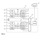
- FIG. 3 a block diagram is shown with components of the end user system 12.
- the personal computer 26 of the end-user system 12 has a plurality of components including a RAM memory element 100, a ROM memory element 102, a keyboard and a display 104, a processor 106, an NVRAM memory 107, other peripheral devices 108, and a network controller 110.
- the components are interconnected in the personal computer 26 via corresponding data lines and bus systems. Via the network controller 110, the personal computer 26 is connected to the internal network 112 of the end user system 12.
- the security module 28 comprises a RAM memory element 114, a ROM memory element 116, a tamper controller 118, an NVRAM memory element 120 or other nonvolatile memory, and a processor 124 and a network controller 126.
- a solid tamper controller 118 is an electronic monitoring circuit that detects when a low constant current through a conductive meander completely enclosing the safety module. Such an interruption is interpreted as a manipulation attempt and leads to the active deletion and destruction of the secret cryptographic keys of the security module 28 in order to effectively and promptly prevent their spying.
- the security module 28 is connected to the internal network 112.
- the network 112 includes a network switch 122.
- a firewall 128 is connected to the internal network 112. Via the firewall 128, a connection to the Internet 22 can be established by the personal computer 26. A data connection from the security module 28 to the Internet 22 and from the Internet 22 to the security module 28 is prevented by the firewall 128.
- the security module 28, 44 is designed as an independent external device which can be connected to the terminal 26 via a network connection.
- the terminal is designed as a personal computer 26.
- the terminal may be any other computing device, such as a laptop, a mobile phone, especially a smartphone, a tablet PC, or any other device that can receive and / or send e-mail messages.
- the security module 28 can also be integrated in a franking machine which serves to frank mailpieces.
- an implementation of the security module as software in the personal computer 26 is possible.
- a modified Blum-Blum-Shub generator can be used as trap-door one-way function.
- a composite integer of sufficient length currently 2048 bits, can be used as the public key.
- the secret key consists of the pair of numbers p and q.
- the associated public key which is deposited with the Internet service provider 18 and / or the Electronic Postage Provider 24 includes S 0 and n.
- S i + 1 For each job i + 1, by the z. If, for example, the message m is to be transmitted as an e-mail message, a transaction number generator generates a transaction number TAN i + 1 and updates its status S i according to s i + 1 according to the following rule: s i + 1 ⁇ s i ⁇ H 2048 m mod n .
- s i denotes the internal state of the transaction number generator after job i and h a one-way hash function that returns values of constant 2048 bits in length.
- the Internet service provider as a checking entity checks the validity of the transmitted TAN i + 1 according to the following rule:
- S i designates the internal state of the generator after the order i.
- only one Internet Service Provider may be provided to perform both the end user system 14 and the end user system 12 communications.
- the function of the provider or Internet service provider described in the exemplary embodiments and in connection with the invention can also be provided by an e-mail service provider which does not allow the end user system 12, 14 access to the Internet. Rather, the end access to the Internet 22 is provided by a separate Internet service provider or other access, and the data transmission over the Internet 22 is used to communicate with the e-mail provider.
- the communication between the components of the end user system 12 with the Internet service provider 18 and with the Electronic Postage Provider 24 as well as with the infrastructure for legally binding e-mail messages is predominantly described for the end user system 12, the Internet service provider 18 and the electronic postal service provider 24.
- the communication of the components of the end user system 14 with each other, between the end user system 14 and the Internet service provider 20 and between the end user system 14 and the electronic postage provider 24. Is the communication of the end user systems 12, 14 for sending the legally binding e-mail Via only one provider 18, 20, the encrypted transmission of the legally binding e-mail between the servers 60, 66 of the providers 18, 20 via the Internet 22 is dispensed with.
Landscapes
- Engineering & Computer Science (AREA)
- Computer Security & Cryptography (AREA)
- Computer Networks & Wireless Communication (AREA)
- Signal Processing (AREA)
- Computer Hardware Design (AREA)
- Computing Systems (AREA)
- General Engineering & Computer Science (AREA)
- Information Transfer Between Computers (AREA)
- Mobile Radio Communication Systems (AREA)
- Data Exchanges In Wide-Area Networks (AREA)
Applications Claiming Priority (1)
| Application Number | Priority Date | Filing Date | Title |
|---|---|---|---|
| DE201010038094 DE102010038094A1 (de) | 2010-10-11 | 2010-10-11 | Verfahren und Anordnung zum rechtsverbindlichen Senden und Empfangen von vertraulichen elektronischen Mitteilungen |
Publications (2)
| Publication Number | Publication Date |
|---|---|
| EP2439902A2 true EP2439902A2 (fr) | 2012-04-11 |
| EP2439902A3 EP2439902A3 (fr) | 2013-03-13 |
Family
ID=44759544
Family Applications (1)
| Application Number | Title | Priority Date | Filing Date |
|---|---|---|---|
| EP11184359A Withdrawn EP2439902A3 (fr) | 2010-10-11 | 2011-10-07 | Procédé et agencement d'émission et de réception contraignantes de communications électroniques confidentielles |
Country Status (3)
| Country | Link |
|---|---|
| US (1) | US8843746B2 (fr) |
| EP (1) | EP2439902A3 (fr) |
| DE (1) | DE102010038094A1 (fr) |
Families Citing this family (3)
| Publication number | Priority date | Publication date | Assignee | Title |
|---|---|---|---|---|
| DE102012106177A1 (de) | 2012-07-10 | 2014-01-16 | Tutao GmbH | Sicheres Übertragungsverfahren |
| US8930274B1 (en) | 2013-10-30 | 2015-01-06 | Google Inc. | Securing payment transactions with rotating application transaction counters |
| US20230124194A1 (en) * | 2020-05-30 | 2023-04-20 | W&W Co., Ltd. | Information processing device, information processing program, and carrier medium |
Family Cites Families (17)
| Publication number | Priority date | Publication date | Assignee | Title |
|---|---|---|---|---|
| US2006674A (en) | 1935-01-24 | 1935-07-02 | Arthur H Diver | Adjustable stepladder |
| US6073242A (en) * | 1998-03-19 | 2000-06-06 | Agorics, Inc. | Electronic authority server |
| US6820202B1 (en) * | 1998-11-09 | 2004-11-16 | First Data Corporation | Account authority digital signature (AADS) system |
| US7334267B2 (en) * | 2001-02-28 | 2008-02-19 | Hall Aluminum Llc | Email viewing security |
| US7380126B2 (en) * | 2001-06-01 | 2008-05-27 | Logan James D | Methods and apparatus for controlling the transmission and receipt of email messages |
| US7627640B2 (en) * | 2003-03-17 | 2009-12-01 | Epostal Services, Inc. | Messaging and document management system and method |
| US7502934B2 (en) * | 2003-12-16 | 2009-03-10 | Sap Aktiengesellschaft | Electronic signatures |
| US20070288746A1 (en) * | 2004-04-02 | 2007-12-13 | Jones Neville R | Method of providing key containers |
| US20050257045A1 (en) * | 2004-04-12 | 2005-11-17 | Bushman M B | Secure messaging system |
| US20060259761A1 (en) * | 2005-05-11 | 2006-11-16 | Vladimir Butenko | Public Key Infrastructure (PKI) Information Encryption by a Non-Sender System |
| WO2007058907A2 (fr) * | 2005-11-10 | 2007-05-24 | Pkware, Inc. | Systemes et methodes pour un echange d'informations fiable |
| TWI307593B (en) * | 2005-12-14 | 2009-03-11 | Chung Shan Inst Of Science | System and method of protecting digital data |
| GB2437558B (en) * | 2006-04-19 | 2010-12-15 | Thales Holdings Uk Plc | Privacy protection system |
| US20080072068A1 (en) * | 2006-09-19 | 2008-03-20 | Wang Liang-Yun | Methods and apparatuses for securing firmware image download and storage by distribution protection |
| US8538028B2 (en) * | 2006-11-20 | 2013-09-17 | Toposis Corporation | System and method for secure electronic communication services |
| ES2381293B1 (es) * | 2009-04-20 | 2012-11-07 | Alter Core, S.L. | Sistema y método de acreditación personal mediante dispositivo móvil. |
| US8543805B2 (en) * | 2010-04-21 | 2013-09-24 | Citrix Systems, Inc. | Systems and methods for split proxying of SSL via WAN appliances |
-
2010
- 2010-10-11 DE DE201010038094 patent/DE102010038094A1/de not_active Withdrawn
-
2011
- 2011-10-07 EP EP11184359A patent/EP2439902A3/fr not_active Withdrawn
- 2011-10-11 US US13/270,583 patent/US8843746B2/en active Active
Non-Patent Citations (1)
| Title |
|---|
| None |
Also Published As
| Publication number | Publication date |
|---|---|
| US20120089846A1 (en) | 2012-04-12 |
| DE102010038094A1 (de) | 2012-04-12 |
| US8843746B2 (en) | 2014-09-23 |
| EP2439902A3 (fr) | 2013-03-13 |
Similar Documents
| Publication | Publication Date | Title |
|---|---|---|
| EP3220597B1 (fr) | Procédé et dispositif destinés à préparer un mot de passe à usage unique | |
| DE69634944T2 (de) | Sichere Benutzerbeglaubigung für elektronischen Handel unter Verwendung eines Wertezählersystems | |
| DE3841393C2 (de) | Zuverlässiges System zur Feststellung der Dokumentenechtheit | |
| DE60212577T2 (de) | Verfahren und vorrichtung zur beglaubigung von daten | |
| DE69725659T2 (de) | Verfahren und Einrichtung zur Ablage eines in einem RSA-Kryptosystem benutzten Geheimschlüssels | |
| DE60023705T2 (de) | Sichere verteilung und schutz einer schlüsselinformation | |
| DE69917803T2 (de) | Nachrichtenidentifizierung mit vertraulichkeit, integrität und ursprungsauthentifizierung | |
| EP2765752B1 (fr) | Procédé destiné à pourvoir un terminal mobile d'un certificat d'authentification | |
| US20060123476A1 (en) | System and method for warranting electronic mail using a hybrid public key encryption scheme | |
| US20050193075A1 (en) | Method, apparatus and system for regulating electronic mail | |
| DE202006020965U1 (de) | Kommunikationssystem zum Bereitstellen der Lieferung einer E-Mail-Nachricht | |
| DE10136608B4 (de) | Verfahren und System zur Echtzeitaufzeichnung mit Sicherheitsmodul | |
| DE10244727B4 (de) | System und Verfahren zur sicheren Datenübertragung | |
| DE102012222995B3 (de) | Verfahren für die sichere Übertragung einer digitalen Nachricht | |
| DE102010038094A1 (de) | Verfahren und Anordnung zum rechtsverbindlichen Senden und Empfangen von vertraulichen elektronischen Mitteilungen | |
| CN100585643C (zh) | 检验数字式免费票据有效性的方法 | |
| EP1337974A1 (fr) | Procede servant a porter des marques d'affranchissement sur des envois postaux | |
| DE69925923T2 (de) | Sicheres datenübertragungssystem | |
| EP1279147A1 (fr) | Procede servant a pourvoir des envois postaux de mentions d'affranchissement | |
| DE102012106177A1 (de) | Sicheres Übertragungsverfahren | |
| DE10242673B4 (de) | Verfahren zur Identifikation eines Benutzers | |
| EP1248432B1 (fr) | Méthode et système d'interrogation de données de certificat utilisant des références de certificat dynamiques | |
| DE102006010821B4 (de) | Selbstzielsuchendes Datenübertragungssystem und Verfahren hierzu | |
| WO2022002502A1 (fr) | Fourniture d'un service de manière anonyme | |
| DE102022112839A1 (de) | Kommunikationssystem, Verfahren und Computerprogrammprodukt zur Bereitstellung von Dokumenten von einem oder mehreren Absendern an mindestens einen Empfänger |
Legal Events
| Date | Code | Title | Description |
|---|---|---|---|
| AK | Designated contracting states |
Kind code of ref document: A2 Designated state(s): AL AT BE BG CH CY CZ DE DK EE ES FI FR GB GR HR HU IE IS IT LI LT LU LV MC MK MT NL NO PL PT RO RS SE SI SK SM TR |
|
| AX | Request for extension of the european patent |
Extension state: BA ME |
|
| PUAI | Public reference made under article 153(3) epc to a published international application that has entered the european phase |
Free format text: ORIGINAL CODE: 0009012 |
|
| PUAL | Search report despatched |
Free format text: ORIGINAL CODE: 0009013 |
|
| RIC1 | Information provided on ipc code assigned before grant |
Ipc: H04L 12/22 20060101ALI20130131BHEP Ipc: H04L 29/06 20060101AFI20130131BHEP |
|
| AK | Designated contracting states |
Kind code of ref document: A3 Designated state(s): AL AT BE BG CH CY CZ DE DK EE ES FI FR GB GR HR HU IE IS IT LI LT LU LV MC MK MT NL NO PL PT RO RS SE SI SK SM TR |
|
| AX | Request for extension of the european patent |
Extension state: BA ME |
|
| STAA | Information on the status of an ep patent application or granted ep patent |
Free format text: STATUS: THE APPLICATION IS DEEMED TO BE WITHDRAWN |
|
| 18D | Application deemed to be withdrawn |
Effective date: 20130914 |