EP2439781A1 - Method for manufacturing solar cell modules - Google Patents
Method for manufacturing solar cell modules Download PDFInfo
- Publication number
- EP2439781A1 EP2439781A1 EP10783239A EP10783239A EP2439781A1 EP 2439781 A1 EP2439781 A1 EP 2439781A1 EP 10783239 A EP10783239 A EP 10783239A EP 10783239 A EP10783239 A EP 10783239A EP 2439781 A1 EP2439781 A1 EP 2439781A1
- Authority
- EP
- European Patent Office
- Prior art keywords
- solar cell
- chamber
- tab lead
- surface electrode
- film
- Prior art date
- Legal status (The legal status is an assumption and is not a legal conclusion. Google has not performed a legal analysis and makes no representation as to the accuracy of the status listed.)
- Withdrawn
Links
Images


Classifications
-
- H—ELECTRICITY
- H10—SEMICONDUCTOR DEVICES; ELECTRIC SOLID-STATE DEVICES NOT OTHERWISE PROVIDED FOR
- H10F—INORGANIC SEMICONDUCTOR DEVICES SENSITIVE TO INFRARED RADIATION, LIGHT, ELECTROMAGNETIC RADIATION OF SHORTER WAVELENGTH OR CORPUSCULAR RADIATION
- H10F71/00—Manufacture or treatment of devices covered by this subclass
-
- H—ELECTRICITY
- H10—SEMICONDUCTOR DEVICES; ELECTRIC SOLID-STATE DEVICES NOT OTHERWISE PROVIDED FOR
- H10F—INORGANIC SEMICONDUCTOR DEVICES SENSITIVE TO INFRARED RADIATION, LIGHT, ELECTROMAGNETIC RADIATION OF SHORTER WAVELENGTH OR CORPUSCULAR RADIATION
- H10F71/00—Manufacture or treatment of devices covered by this subclass
- H10F71/137—Batch treatment of the devices
- H10F71/1375—Apparatus for automatic interconnection of photovoltaic cells in a module
-
- B—PERFORMING OPERATIONS; TRANSPORTING
- B32—LAYERED PRODUCTS
- B32B—LAYERED PRODUCTS, i.e. PRODUCTS BUILT-UP OF STRATA OF FLAT OR NON-FLAT, e.g. CELLULAR OR HONEYCOMB, FORM
- B32B17/00—Layered products essentially comprising sheet glass, or glass, slag, or like fibres
- B32B17/06—Layered products essentially comprising sheet glass, or glass, slag, or like fibres comprising glass as the main or only constituent of a layer, next to another layer of a specific material
- B32B17/10—Layered products essentially comprising sheet glass, or glass, slag, or like fibres comprising glass as the main or only constituent of a layer, next to another layer of a specific material of synthetic resin
- B32B17/10005—Layered products essentially comprising sheet glass, or glass, slag, or like fibres comprising glass as the main or only constituent of a layer, next to another layer of a specific material of synthetic resin laminated safety glass or glazing
- B32B17/10009—Layered products essentially comprising sheet glass, or glass, slag, or like fibres comprising glass as the main or only constituent of a layer, next to another layer of a specific material of synthetic resin laminated safety glass or glazing characterized by the number, the constitution or treatment of glass sheets
- B32B17/10018—Layered products essentially comprising sheet glass, or glass, slag, or like fibres comprising glass as the main or only constituent of a layer, next to another layer of a specific material of synthetic resin laminated safety glass or glazing characterized by the number, the constitution or treatment of glass sheets comprising only one glass sheet
-
- B—PERFORMING OPERATIONS; TRANSPORTING
- B32—LAYERED PRODUCTS
- B32B—LAYERED PRODUCTS, i.e. PRODUCTS BUILT-UP OF STRATA OF FLAT OR NON-FLAT, e.g. CELLULAR OR HONEYCOMB, FORM
- B32B17/00—Layered products essentially comprising sheet glass, or glass, slag, or like fibres
- B32B17/06—Layered products essentially comprising sheet glass, or glass, slag, or like fibres comprising glass as the main or only constituent of a layer, next to another layer of a specific material
- B32B17/10—Layered products essentially comprising sheet glass, or glass, slag, or like fibres comprising glass as the main or only constituent of a layer, next to another layer of a specific material of synthetic resin
- B32B17/10005—Layered products essentially comprising sheet glass, or glass, slag, or like fibres comprising glass as the main or only constituent of a layer, next to another layer of a specific material of synthetic resin laminated safety glass or glazing
- B32B17/1055—Layered products essentially comprising sheet glass, or glass, slag, or like fibres comprising glass as the main or only constituent of a layer, next to another layer of a specific material of synthetic resin laminated safety glass or glazing characterized by the resin layer, i.e. interlayer
- B32B17/10788—Layered products essentially comprising sheet glass, or glass, slag, or like fibres comprising glass as the main or only constituent of a layer, next to another layer of a specific material of synthetic resin laminated safety glass or glazing characterized by the resin layer, i.e. interlayer containing ethylene vinylacetate
-
- B—PERFORMING OPERATIONS; TRANSPORTING
- B32—LAYERED PRODUCTS
- B32B—LAYERED PRODUCTS, i.e. PRODUCTS BUILT-UP OF STRATA OF FLAT OR NON-FLAT, e.g. CELLULAR OR HONEYCOMB, FORM
- B32B17/00—Layered products essentially comprising sheet glass, or glass, slag, or like fibres
- B32B17/06—Layered products essentially comprising sheet glass, or glass, slag, or like fibres comprising glass as the main or only constituent of a layer, next to another layer of a specific material
- B32B17/10—Layered products essentially comprising sheet glass, or glass, slag, or like fibres comprising glass as the main or only constituent of a layer, next to another layer of a specific material of synthetic resin
- B32B17/10005—Layered products essentially comprising sheet glass, or glass, slag, or like fibres comprising glass as the main or only constituent of a layer, next to another layer of a specific material of synthetic resin laminated safety glass or glazing
- B32B17/10807—Making laminated safety glass or glazing; Apparatus therefor
- B32B17/10816—Making laminated safety glass or glazing; Apparatus therefor by pressing
- B32B17/10871—Making laminated safety glass or glazing; Apparatus therefor by pressing in combination with particular heat treatment
-
- H—ELECTRICITY
- H10—SEMICONDUCTOR DEVICES; ELECTRIC SOLID-STATE DEVICES NOT OTHERWISE PROVIDED FOR
- H10F—INORGANIC SEMICONDUCTOR DEVICES SENSITIVE TO INFRARED RADIATION, LIGHT, ELECTROMAGNETIC RADIATION OF SHORTER WAVELENGTH OR CORPUSCULAR RADIATION
- H10F19/00—Integrated devices, or assemblies of multiple devices, comprising at least one photovoltaic cell covered by group H10F10/00, e.g. photovoltaic modules
-
- H—ELECTRICITY
- H10—SEMICONDUCTOR DEVICES; ELECTRIC SOLID-STATE DEVICES NOT OTHERWISE PROVIDED FOR
- H10F—INORGANIC SEMICONDUCTOR DEVICES SENSITIVE TO INFRARED RADIATION, LIGHT, ELECTROMAGNETIC RADIATION OF SHORTER WAVELENGTH OR CORPUSCULAR RADIATION
- H10F19/00—Integrated devices, or assemblies of multiple devices, comprising at least one photovoltaic cell covered by group H10F10/00, e.g. photovoltaic modules
- H10F19/80—Encapsulations or containers for integrated devices, or assemblies of multiple devices, having photovoltaic cells
-
- H—ELECTRICITY
- H10—SEMICONDUCTOR DEVICES; ELECTRIC SOLID-STATE DEVICES NOT OTHERWISE PROVIDED FOR
- H10F—INORGANIC SEMICONDUCTOR DEVICES SENSITIVE TO INFRARED RADIATION, LIGHT, ELECTROMAGNETIC RADIATION OF SHORTER WAVELENGTH OR CORPUSCULAR RADIATION
- H10F19/00—Integrated devices, or assemblies of multiple devices, comprising at least one photovoltaic cell covered by group H10F10/00, e.g. photovoltaic modules
- H10F19/90—Structures for connecting between photovoltaic cells, e.g. interconnections or insulating spacers
- H10F19/902—Structures for connecting between photovoltaic cells, e.g. interconnections or insulating spacers for series or parallel connection of photovoltaic cells
- H10F19/906—Structures for connecting between photovoltaic cells, e.g. interconnections or insulating spacers for series or parallel connection of photovoltaic cells characterised by the materials of the structures
-
- H—ELECTRICITY
- H10—SEMICONDUCTOR DEVICES; ELECTRIC SOLID-STATE DEVICES NOT OTHERWISE PROVIDED FOR
- H10F—INORGANIC SEMICONDUCTOR DEVICES SENSITIVE TO INFRARED RADIATION, LIGHT, ELECTROMAGNETIC RADIATION OF SHORTER WAVELENGTH OR CORPUSCULAR RADIATION
- H10F77/00—Constructional details of devices covered by this subclass
- H10F77/93—Interconnections
- H10F77/933—Interconnections for devices having potential barriers
- H10F77/935—Interconnections for devices having potential barriers for photovoltaic devices or modules
-
- Y—GENERAL TAGGING OF NEW TECHNOLOGICAL DEVELOPMENTS; GENERAL TAGGING OF CROSS-SECTIONAL TECHNOLOGIES SPANNING OVER SEVERAL SECTIONS OF THE IPC; TECHNICAL SUBJECTS COVERED BY FORMER USPC CROSS-REFERENCE ART COLLECTIONS [XRACs] AND DIGESTS
- Y02—TECHNOLOGIES OR APPLICATIONS FOR MITIGATION OR ADAPTATION AGAINST CLIMATE CHANGE
- Y02E—REDUCTION OF GREENHOUSE GAS [GHG] EMISSIONS, RELATED TO ENERGY GENERATION, TRANSMISSION OR DISTRIBUTION
- Y02E10/00—Energy generation through renewable energy sources
- Y02E10/50—Photovoltaic [PV] energy
Definitions
- the present invention relates to a method for manufacturing a solar cell module in which a solar cell having a surface electrode to which a tab lead is connected is sealed with a resin.
- a solar cell module the front surface of one of adjacent solar cells and the rear surface of the other solar cell are first connected by solder-coated copper foil ribbons used as tab leads. This procedure is repeated for a plurality of solar cells to produce a solar cell unit. Next, transparent ethylene-vinyl acetate copolymer (EVA) sheets used as a sealing resin are disposed on both sides of the solar cell unit. If necessary, a transparent protection plate such as a transparent glass plate is disposed on the front side, and a light-resistant resin sheet is disposed on the rear side. The entire stacked product obtained is subjected to thermo-compression bonding to produce the solar cell module (paragraphs 0003 to 0010 in Patent Literature 1).
- EVA transparent ethylene-vinyl acetate copolymer
- Patent Literature 2 states that the use of the vacuum laminator can prevent the occurrence of voids in the thermo-compression bonded areas.
- a tab lead connecting step the temperature when the solder-coated tab leads are connected to the solar cells (a tab lead connecting step) is relatively high, i.e., 240°C or higher, and the temperature during resin-sealing with the EVA sheets (a resin sealing step) is relatively low, i.e., about 150°C.
- the temperatures in these steps are different as described above. Therefore, these steps must be performed separately in time. This causes an increase in manufacturing tact time and an increase in frequency of handling, resulting in a problem that the manufacturing cost increases.
- the high temperature during the tab lead connecting step causes accumulation of internal stress in the solar cells, failure such as cracks may occur in the solar cells during the resin sealing step.
- a relatively low temperature i.e., the temperature used in the resin sealing step
- conductive adhesive films that can establish connection at the temperature used during resin-sealing with an EVA sheet are placed on solar cells. Then tab leads are placed on the conductive adhesive films, and the EVA sheet is placed thereon. If necessary, a transparent protection plate such as a transparent glass plate is placed on the front side, and a light-resistant resin sheet is placed on the rear side. Then the entire stacked product obtained is resin-sealed by thermo-compression bonding.
- an adhesive 93 such as a conductive adhesive paste (AP), a conductive adhesive film (AF), an anisotropic conductive paste (ACP), an anisotropic conductive adhesive film (ACF), a non-conductive adhesive paste (NCP), or a non-conductive adhesive film (NCF)
- a tab lead 94, an EVA sheet 95, and an optional moisture-proof sheet 96 are stacked on a solar cell 92 provided with a surface electrode 91, and the stacked product is subjected to vacuum lamination processing.
- the side surfaces of the layer of the adhesive 93 are covered with the compressed EVA, and therefore the resin component in the adhesive 93 is not removed from the connection portion. This may cause a problem that reliable connection is not achieved.
- the adhesive 93 is a conductive adhesive film
- the conductive particles contained therein are not sufficiently crushed, so that reliable conductive connection may not be achieved. Therefore, even when a conductive adhesive film is used as the adhesive, the tab lead connecting step and the resin sealing step must still be performed separately in time.
- the present invention solves the foregoing conventional problems. It is an object of the invention to allow, when a solar cell having a surface electrode to which a tab lead is connected is sealed with a resin to produce a solar cell module, a tab lead connecting step of connecting the tab lead to the surface electrode and a resin sealing step of sealing the solar cell with the sealing resin to be performed simultaneously at a relatively low temperature used in the resin sealing step.
- the present inventors have found that the following three means are effective to connect a tab lead to an electrode of a solar cell and seal the solar cell with a resin simultaneously at a relatively low temperature used for the resin-sealing of the solar cell.
- the first means is such that, in order to squeeze the adhesive out of the connection area when the tab lead is connected to the surface electrode of the solar cell with an adhesive (such as a CP, CF, ACP, ACF, NCP, or NCF), a pressurizing film is disposed between the tab lead and the sealing resin so that the pressing pressure of the sealing resin can be applied to a connection area while the connection area is separated from the sealing resin.
- the second means is such that, when the tab lead is connected to the surface electrode of the solar cell through a conductive adhesive film, conductive particles for conductive connection contained in the conductive adhesive film are caused to protrude from the base of the adhesive film so that the conductive particles can be crushed without the spread of the resin forming the adhesive film to the outside of a connection area.
- the third means is such that, when the tab lead itself is brought into direct contact with the solar cell having a surface electrode and is connected thereto with a thermosetting adhesive, the tab lead used includes a thermosetting adhesive layer formed on one side of a metal substrate, and convex portions of the metal substrate protrude from the thermosetting adhesive layer so that the tab lead can be directly connected to the surface electrode without the spread of the thermosetting adhesive to the outside of a connection area.
- a first embodiment of the present invention provides a method for manufacturing a solar cell module in which a solar cell having a surface electrode to which a tab lead is connected with an adhesive is sealed with a resin using a vacuum laminator, the method comprising:
- a second embodiment of the present invention provides a method for manufacturing a solar cell module in which a solar cell having a surface electrode to which a tab lead is connected through a conductive adhesive film is sealed with a resin using a vacuum laminator, the method comprising:
- a third embodiment of the present invention provides a method for manufacturing a solar cell module in which a solar cell having a surface electrode to which a tab lead is connected is sealed with a resin using a vacuum laminator, the method comprising:
- the first embodiment of the method for manufacturing a solar cell module of the present invention is configured such that, in order to squeeze the adhesive out of the connection area when the tab lead is connected to the surface electrode of the solar cell with an adhesive (such as a CP, CF, ACP, ACF, NCP, or NCF), a pressurizing film is disposed between the tab lead and the sealing resin so that the pressing pressure of the sealing resin can be applied to the connection area while the connection area is separated from the sealing resin.
- an adhesive such as a CP, CF, ACP, ACF, NCP, or NCF
- the second embodiment is configured such that, when the tab lead is connected to the surface electrode of the solar cell through a conductive adhesive film, the conductive particles for conductive connection contained in the conductive adhesive film are caused to protrude from the base of the adhesive film so that the conductive particles can be crushed without the spread of the resin forming the adhesive film to the outside of a connection area.
- the third embodiment is configured such that, when the tab lead itself is brought into direct contact with the solar cell having a surface electrode and is connected thereto with a thermosetting adhesive, the tab lead used includes a thermosetting adhesive layer formed on one side of a metal substrate, and convex portions of the metal substrate protrude from the thermosetting adhesive layer so that the tab lead can be directly connected to the surface electrode without the spread of the thermosetting adhesive to the outside of a connection area. Therefore, with any of the embodiments, the tab lead and the surface electrode of the solar cell can be thermo-compression bonded using a vacuum laminator with high connection reliability. Simultaneously, the solar cell can be sealed with a resin. When a convex portion is provided, instead of the convex portion formed on the tab lead, on the surface electrode, the same advantageous effects can be obtained.
- a first embodiment of the present invention is a method for manufacturing a solar cell module in which a solar cell having a surface electrode to which a tab lead is connected with an adhesive is sealed with a resin using a vacuum laminator.
- the vacuum laminator used in the present invention includes a first chamber and a second chamber partitioned by a flexible sheet.
- the inner pressures of these chambers can be controlled independently, and a heating stage for heating is provided in the second chamber.
- An example of such a vacuum laminator will be described in more detail with reference to Fig. 1 .
- Fig. 1 shows the vacuum laminator 10 before use, and the vacuum laminator 10 includes an upper unit 11 and a lower unit 12. These units are separably integrated through a sealing member 13 such as an O-ring.
- a flexible sheet 14 of, for example, silicon rubber is provided in the upper unit 11, and the vacuum laminator 10 is partitioned into a first chamber 15 and a second chamber 16 by the flexible sheet 14.
- a thin glass cloth-reinforced Teflon (registered trademark) sheet may be disposed on that surface.
- Pipes 17 and 18 are provided for the upper unit 11 and the lower unit 12, respectively, so that the inner pressures of the respective chambers can be controlled independently, i.e., the pressures can be reduced and increased by vacuum pumps or compressors and the chambers can be open to the air.
- the pipe 17 is branched into two directions 17a and 17b through a switching valve 19, and the pipe 18 is branched into two directions 18a and 18b through a switching valve 20.
- a heating stage 21 is provided in the lower unit 12.
- This vacuum laminator 10 is used as shown in, for example, Figs. 2A to 2E .
- the upper unit 11 and the lower unit 12 are separated from each other, and a stacked product 22 to be thermo-compression bonded is placed on the stage 21.
- the upper unit 11 and the lower unit 12 are separably integrated through the sealing member 13.
- vacuum pumps (not shown) are connected to the pipes 17a and 18a to evacuate the first chamber 15 and the second chamber 16 to a high vacuum.
- the switching valve 19 is switched to introduce air to the first chamber 15 through the pipe 17b, as shown in Fig. 2C .
- the flexible sheet 14 is thereby expanded toward the second chamber 16. Therefore, the stacked product 22 is pressed by the flexible sheet 14 while being heated by the stage 21.
- the switching valve 20 is switched to introduce air to the second chamber 16 through the pipe 18b. Then the flexible sheet 14 is pushed back toward the first chamber 15, and the internal pressures of the first chamber 15 and the second chamber 16 eventually become the same.
- thermo-compression bonded stacked product 22 is removed from the heating stage 21.
- the operation cycle of the vacuum laminator 10 is thereby completed, and the process returns to Fig. 2A .
- the stacked product 22 is a stack in which a conductive adhesive film is sandwiched between the surface electrode of a solar cell and a tab lead and a sealing resin layer is disposed over the entire surface of the solar cell
- the operations shown in Figs. 2A to 2D allow the conductive connection between the surface electrode and the tab lead and the resin-sealing of the conductive connection portion to be achieved simultaneously.
- the vacuum laminator used in the present invention has been described above.
- the usable vacuum laminator is not limited to the vacuum laminator including the upper unit 11 and the lower unit 12 shown in Fig. 1 .
- a vacuum laminator including one casing divided into two chambers and configured such that a stacked product is placed and removed through an open-close door may also be used.
- the first and second chambers may be designed such that compressed air is introduced to the first chamber to perform pressurization at a pressure equal to or higher than atmospheric pressure. In this case, the air inside the second chamber may be simply discharged without reducing the pressure inside the second chamber.
- a solar cell 32 having a surface electrode 31 formed thereon is stacked on the heating stage 21 in the second chamber 16 of the vacuum laminator partitioned from the first chamber 15 by the flexible sheet 14. Then, an adhesive 33 on the surface electrode 31, a tab lead 34 on the adhesive 33, a pressurizing film 35 on the tab lead 34, a sealing resin layer 36 on the pressurizing film 35, and a moisture-proof back sheet 37 or a glass plate (not shown) on the sealing resin layer 36 are sequentially stacked.
- the internal pressure of the first chamber of the vacuum laminator is increased relative to the internal pressure of the second chamber to press the flexible sheet 14 against the moisture-proof back sheet 37 or the glass plate, and simultaneously the solar cell 32 is heated by the heating stage 21.
- the surface electrode 31 of the solar cell 32 is thereby connected to the tab lead 34, and the solar cell 32 is resin-sealed with the sealing resin layer 36.
- a solar cell module 30 can be obtained in this manner ( Fig. 3C ).
- Preferred examples of the operation for increasing the internal pressure of the first chamber 15 of the vacuum laminator relative to the internal pressure of the second chamber 16 include an operation including reducing the internal pressures of the first chamber 15 and the second chamber 16 and then opening the first chamber 15 to the air while the reduced pressure inside the second chamber 16 is maintained.
- any of the known adhesives such as conductive adhesive pastes (CPs), conductive adhesive films (CFs), anisotropic conductive pastes (ACPs), anisotropic conductive adhesive films (ACFs), non-conductive adhesive pastes (NCPs), and non-conductive adhesive films (NCFs), used when electronic components are mounted on a solar cell can be used as the adhesive 33.
- a thermosetting adhesive is preferably used.
- the pressurizing film 35 Any of resin films, synthetic paper sheets, nonwoven fabrics, and the like that have thicknesses of 5 to 500 ⁇ m and exhibit dimensional stability even during heating and pressurization by the vacuum laminator can be used as the pressurizing film 35. Any of polyamide, polyimide, polyester, and the like can be used as the material that forms the pressurizing film 35.
- the glass transition temperature of the pressurizing film 35 is higher than the laminating temperature of the sealing resin layer 36. Specifically, the glass transition temperature is at least 10°C higher than the laminating temperature.
- the circumferential edges of the pressurizing film 35 are resin-sealed with the sealing resin layer 36.
- a pressurizing film having no adhesive properties can be used as the pressurizing film 35.
- a sealing resin layer formed of any of the known liquid- and paste-like sealing resin compositions can be used as the sealing resin layer 36, and a sealing resin sheet formed into a sheet shape is particularly preferably used. Specifically, a thermoplastic ethylene/vinyl acetate copolymer sheet having good sealing and adhesive properties can be preferably used.
- the sealing resin layer 36 flows when heated during resin-sealing and covers areas to be sealed. When the sealing resin layer 36 contains a curable component, good resin-sealing can be achieved by curing the sealing resin layer 36 after it flows.
- the solar cell 32 having the surface electrode 31 is a solar cell required to be bonded to a tab lead and to be sealed with a resin.
- a solar cell include crystalline solar cells using crystalline photoelectric conversion elements and thin-film solar cells using thin-film photoelectric conversion elements.
- a surface electrode may also be provided on the rear surface of the solar cell.
- a solar cell unit composed of a plurality of solar cells can be formed (see Fig. 8 in Patent Literature 1 and Fig. 1 in Patent Literature 2).
- Any of the known materials can be used as the material of the photoelectric conversion element of the solar cell. Examples of such materials include single crystalline silicon, polycrystalline silicon, amorphous silicon, single crystalline compounds such as GaAs-based compounds, and polycrystalline compounds such as CdS and CdTe.
- the tab leads are used as inner leads for connecting the solar cells to each other or outer leads for outputting power.
- Solder-coated copper foil ribbons may be preferably used as the tab leads.
- the moisture-proof back sheet 37 or the glass plate is stacked on the sealing resin layer 36.
- the moisture-proof back sheet 37 or the glass plate used can be appropriately selected from those used in conventional solar cell modules.
- the second embodiment of the present invention is a manufacturing method including sealing, with a resin using a vacuum laminator, a solar cell having a surface electrode to which a tab lead is connected through an isotropic or anisotropic conductive adhesive film (CF or ACF).
- a conductive adhesive film 41 used includes a thermosetting resin film base 42 and conductive particles 43 having a particle diameter larger than the thickness of the base and held therein, as shown in Fig. 4A .
- the conductive particles 43 protrude from at least one side of the thermosetting resin film base 42. Since the conductive particles 43 protrude from the thermosetting resin film base 42 as described above, the spaces between the conductive particles 43 accommodate the conductive particles 43 that have been crushed. Therefore, the conductive particles in the conductive adhesive film can be sufficiently crushed to establish conductive connection without using the pressurizing film used in the first embodiment.
- a thermosetting resin thin film (not shown) may be formed on the surface of each protruding conductive particle 43 within a range in which the effect of the present invention is not impaired.
- the second embodiment is advantageous in that, even when it is applied to the light-receiving side, a reduction in light-receiving efficiency due to the use of a pressurizing film is not required to be taken into consideration.
- a solar cell 32 having a surface electrode 31 formed thereon is first stacked on the heating stage 21 in the second chamber 16 of the vacuum laminator partitioned from the first chamber 15 by the flexible sheet 14. Then a conductive adhesive film 41 on the surface electrode 31, a tab lead 34 on the conductive adhesive film 41, a sealing resin layer 36 on the tab lead 34, and a moisture-proof back sheet 37 or a glass plate (not shown) on the sealing resin layer 36 are sequentially stacked. Note that the conductive adhesive film 41 is stacked on the surface electrode 31 such that the surface of the conductive adhesive film 41 from which the conductive particles protrude faces the surface electrode 31.
- the internal pressure of the first chamber of the vacuum laminator is increased relative to the internal pressure of the second chamber to press the flexible sheet 14 against the moisture-proof back sheet 37 or the glass plate, and simultaneously the solar cell 32 is heated by the heating stage 21.
- the surface electrode 31 of the solar cell 32 is thereby conductively connected to the tab lead 34, and the connection area of the solar cell 32 is resin-sealed with the sealing resin layer 36.
- a solar cell module 40 can be obtained in this manner ( Fig. 4D ).
- the third embodiment of the present invention is a method for manufacturing a solar cell module in which a solar cell having a surface electrode to which a tab lead is connected is sealed with a resin using a vacuum laminator.
- a description will be given of the case in which convex portions are formed on the tab lead.
- the tab lead 51 used includes a metal substrate 52 and a thermosetting adhesive layer 53 formed on one side thereof, and convex portions 52a of the metal substrate 52 protrude from the thermosetting adhesive layer 53 so as to be connectable to the surface electrode. Since the convex portions 52a of the metal substrate 52 protrude from the thermosetting adhesive layer 53 as described above, the spaces between the convex portions 52a accommodate the convex portions 52a that have been crushed. Therefore, conductive connection can be established without using the pressurizing film used in the first embodiment.
- a thermosetting adhesive thin film (not shown) may be formed on the surface of each convex portion 52a within a range in which the effect of the present invention is not impaired.
- a solar cell 32 having a surface electrode 31 formed thereon is first stacked on the heating stage 21 in the second chamber 16 of the vacuum laminator partitioned from the first chamber 15 by the flexible sheet 14. Then the tab lead 51 on the surface electrode 31, a sealing resin layer 36 on the tab lead 51, a moisture-proof back sheet 37 or a glass plate (not shown) on the sealing resin layer 36 are sequentially stacked. Note that the tab lead 51 is stacked on the surface electrode 31 such that the surface of the tab lead 51 from which the convex portions 52a of the metal substrate 52 protrude faces the surface electrode 31.
- the internal pressure of the first chamber of the vacuum laminator is increased relative to the internal pressure of the second chamber to press the flexible sheet 14 against the moisture-proof back sheet 37 or the glass plate, and simultaneously the solar cell 32 is heated by the heating stage 21.
- the surface electrode 31 of the solar cell 32 is thereby conductively connected to the tab lead 51, and the connection area of the solar cell 32 is resin-sealed with the sealing resin layer 36.
- a solar cell module 50 can be obtained in this manner ( Fig. 5D ).
- the third embodiment is advantageous in that, even when it is applied to the light-receiving side, a reduction in light-receiving efficiency due to the use of a pressurizing film is not required to be taken into consideration.
- the third embodiment of the present invention in which the convex portions are formed on the surface electrode is a method for manufacturing a solar cell module in which a solar cell having a surface electrode to which a tab lead is connected is sealed with a resin using a vacuum laminator.
- the method is characterized by:
- the solar cell module manufacturing method in which a tab lead is connected to one side of a solar cell and simultaneously the solar cell is sealed with a resin has been described in detail, but the present invention is not limited thereto.
- a method in which tab leads for series connection are connected to opposite sides of solar cells that use crystalline photoelectric conversion elements and then the solar cells are sealed with a resin as shown in Fig. 8A is also within the range of the present invention.
- a method in which tabs for outputting power are connected to outermost ones of long thin-film photoelectric conversion elements of a solar cell module that are connected directly in a horizontal direction as shown in Fig. 8B is within the range of the present invention.
- a plurality of solar cells are prepared. Then a second end of a tab lead 34 having a first end temporarily applied to the rear-side electrode (not shown) of a solar cell 32a is temporarily applied to the front-side electrode (not shown) of an adjacent solar cell 32b through an adhesive under pressure at room temperature or at a low temperature (about 30 to 120°C). The formation of such a temporarily applied pattern is performed for the plurality of solar cells to obtain a solar cell unit 100.
- a solar cell module including the solar cell unit composed of a plurality of solar cells can be obtained.
- thin-film solar cells 32 including thin-film photoelectric conversion elements are arranged in series in a plane direction on a substrate 38.
- Tab leads 34 for outputting power are temporarily applied to the surface electrodes (not shown) of an outermost solar cell 32c and another outermost solar cell 32d through an adhesive under pressure at room temperature or at a low temperature (about 30 to 120°C) to obtain a solar cell unit 100.
- a solar cell module including the solar cell unit composed of a plurality of solar cells can be obtained.
- a pressurizing film having a lead wire pre-stacked thereon may be used.
- the first embodiment of the present invention was implemented using the following materials as substitutes for the materials of the solar cell.
- the glass substrate was placed on the heating stage in the second chamber of the vacuum laminator shown in Fig. 1 .
- the conductive adhesive film (width: 2 mm, length: 5 mm, and thickness: 0.05 mm) was placed on the surface of the glass substrate, and the tab lead, the pressurizing film, the sealing resin sheet, and the moisture-proof back sheet were placed on the conductive adhesive film.
- the heating stage was maintained at 150°C
- the pressures of the first and second chambers were reduced to 133 Pa.
- air was introduced to the first chamber to bring it to atmospheric pressure.
- the obtained stacked product was observed under a microscope from the rear side (the glass surface side), and the conductive particles were found to be crushed ( Fig. 6A ).
- a stacked product was obtained by the same procedure as in Example 1 except that a conductive adhesive paste obtained by mixing 50 parts by mass of an epoxy resin (EP828, Japan Epoxy Resin Co., Ltd.), 40 parts by mass of a curing agent (HX3941, Asahi Kasei Chemicals Corporation), and 10 parts by mass of conductive particles (AUL, Sekisui Chemical Co., Ltd.) having an average particle diameter of 10 ⁇ m was used instead of the conductive adhesive film and that the conductive adhesive paste was applied to the surface of the glass substrate to a width of 2 mm, a length of 5 mm, and a thickness of 0.05mm.
- the obtained stacked product was observed under a microscope from the rear side (the glass surface side), and the conductive particles were found to be crushed.
- a stacked product was obtained by repeating the same procedure as in Example 1 except that the pressurizing film was not used.
- the obtained stacked product was observed under a microscope from the rear side (the glass surface side), and crushed conductive particles were not found ( Fig. 6B ) .
- the second embodiment of the present invention was implemented using the following materials as substitutes for the materials of the solar cell.
- the glass substrate with ITO was placed on the heating stage in the second chamber of the vacuum laminator shown in Fig. 1 .
- the tab lead was temporarily applied to the glass substrate with the conductive adhesive film (of the type in which conductive particles protruded from the surface of the film) facing the ITO electrode on the surface of the glass substrate, and the sealing resin sheet and the polyethylene terephthalate film with a thickness of 80 ⁇ m were placed thereon.
- the heating stage was maintained at 150°C
- the pressures of the first and second chambers were reduced to 133 Pa.
- air was introduced to the first chamber to bring it to atmospheric pressure.
- the obtained stacked product was observed under a microscope from the rear side (the glass surface side), and the conductive particles were found to be crushed ( Fig. 7A ).
- the resistance value was measured and found to be 5 m ⁇ .
- a stacked product was obtained by repeating the same procedure as in Example 2 except that the conductive adhesive film produced in Example 1 was used.
- the obtained stacked product was observed under a microscope from the rear side (the glass surface side), and crushed conductive particles were not found ( Fig. 7B ). The measurement of resistance value was attempted, and the resistance value could not be measured. Electric connection was not established.
- the third embodiment of the present invention was implemented using the following materials as substitutes for the materials of the solar cell.
- the glass substrate was placed on the heating stage in the second chamber of the vacuum laminator shown in Fig. 1 .
- the tab lead was temporarily applied to the glass substrate such that the convex protrusions of the tab lead faced the ITO electrode on the surface of the glass substrate, and the sealing resin sheet and the polyethylene terephthalate film with a thickness of 80 ⁇ m were placed thereon.
- the heating stage was maintained at 150°C
- the pressures of the first and second chambers were reduced to 133 Pa.
- air was introduced to the first chamber to bring it to atmospheric pressure.
- the obtained stacked product was observed under a microscope from the rear side (the glass surface side), and the convex protrusions were found to be crushed.
- the resistance value was measured and found to be 5 m ⁇ .
- a stacked product was obtained by repeating the same procedure as in Example 2 except that a flat tab lead having no convex protrusions formed thereon was used. The resistance value of the obtained stacked product was measured and found to be open.
- Each of the manufacturing methods of the present invention is used to manufacture a solar cell module in which a solar cell having a surface electrode to which a tab lead is connected is sealed with a resin.
- the tab lead connecting step of connecting the surface electrode to the tab lead and the resin sealing step of sealing the solar cell with a sealing resin can be performed simultaneously at a relatively low temperature, i.e., the temperature for the resin sealing step. Therefore, the manufacturing method is useful for the manufacturing of a solar cell and a solar cell unit including a combination of solar cells.
- the manufacturing method is useful for a crystalline solar cell when an inner lead is connected to a bus bar electrode formed by screen printing using silver paste and useful for a thin-film solar cell when a surface electrode is connected to an outer lead.
Landscapes
- Physics & Mathematics (AREA)
- Thermal Sciences (AREA)
- Photovoltaic Devices (AREA)
Abstract
Description
- The present invention relates to a method for manufacturing a solar cell module in which a solar cell having a surface electrode to which a tab lead is connected is sealed with a resin.
- Conventionally, to manufacture a solar cell module, the front surface of one of adjacent solar cells and the rear surface of the other solar cell are first connected by solder-coated copper foil ribbons used as tab leads. This procedure is repeated for a plurality of solar cells to produce a solar cell unit. Next, transparent ethylene-vinyl acetate copolymer (EVA) sheets used as a sealing resin are disposed on both sides of the solar cell unit.
If necessary, a transparent protection plate such as a transparent glass plate is disposed on the front side, and a light-resistant resin sheet is disposed on the rear side. The entire stacked product obtained is subjected to thermo-compression bonding to produce the solar cell module (paragraphs 0003 to 0010 in Patent Literature 1).
It has also been proposed to use a vacuum laminator including a pressure-reducing unit and a heating plate when thermo-compression bonding is performed (Patent Literature 2). Patent Literature 2 states that the use of the vacuum laminator can prevent the occurrence of voids in the thermo-compression bonded areas. -
- Patent Literature 1: Japanese Patent Application Laid-Open No.
2002-319691 - Patent Literature 2: Japanese Patent Application Laid-Open No.
2004-356349 - However, the temperature when the solder-coated tab leads are connected to the solar cells (a tab lead connecting step) is relatively high, i.e., 240°C or higher, and the temperature during resin-sealing with the EVA sheets (a resin sealing step) is relatively low, i.e., about 150°C. The temperatures in these steps are different as described above. Therefore, these steps must be performed separately in time. This causes an increase in manufacturing tact time and an increase in frequency of handling, resulting in a problem that the manufacturing cost increases. In addition, since the high temperature during the tab lead connecting step causes accumulation of internal stress in the solar cells, failure such as cracks may occur in the solar cells during the resin sealing step.
- To perform the tab lead connecting step and the resin sealing step simultaneously at a relatively low temperature, i.e., the temperature used in the resin sealing step, for example, conductive adhesive films that can establish connection at the temperature used during resin-sealing with an EVA sheet are placed on solar cells. Then tab leads are placed on the conductive adhesive films, and the EVA sheet is placed thereon. If necessary, a transparent protection plate such as a transparent glass plate is placed on the front side, and a light-resistant resin sheet is placed on the rear side. Then the entire stacked product obtained is resin-sealed by thermo-compression bonding.
- In
Fig. 9 , an adhesive 93 such as a conductive adhesive paste (AP), a conductive adhesive film (AF), an anisotropic conductive paste (ACP), an anisotropic conductive adhesive film (ACF), a non-conductive adhesive paste (NCP), or a non-conductive adhesive film (NCF)), atab lead 94, anEVA sheet 95, and an optional moisture-proof sheet 96 are stacked on asolar cell 92 provided with asurface electrode 91, and the stacked product is subjected to vacuum lamination processing. However, in this case, the side surfaces of the layer of theadhesive 93 are covered with the compressed EVA, and therefore the resin component in theadhesive 93 is not removed from the connection portion. This may cause a problem that reliable connection is not achieved. In particular, when theadhesive 93 is a conductive adhesive film, the conductive particles contained therein are not sufficiently crushed, so that reliable conductive connection may not be achieved. Therefore, even when a conductive adhesive film is used as the adhesive, the tab lead connecting step and the resin sealing step must still be performed separately in time. - The present invention solves the foregoing conventional problems. It is an object of the invention to allow, when a solar cell having a surface electrode to which a tab lead is connected is sealed with a resin to produce a solar cell module, a tab lead connecting step of connecting the tab lead to the surface electrode and a resin sealing step of sealing the solar cell with the sealing resin to be performed simultaneously at a relatively low temperature used in the resin sealing step.
- The present inventors have found that the following three means are effective to connect a tab lead to an electrode of a solar cell and seal the solar cell with a resin simultaneously at a relatively low temperature used for the resin-sealing of the solar cell. The first means is such that, in order to squeeze the adhesive out of the connection area when the tab lead is connected to the surface electrode of the solar cell with an adhesive (such as a CP, CF, ACP, ACF, NCP, or NCF), a pressurizing film is disposed between the tab lead and the sealing resin so that the pressing pressure of the sealing resin can be applied to a connection area while the connection area is separated from the sealing resin. The second means is such that, when the tab lead is connected to the surface electrode of the solar cell through a conductive adhesive film, conductive particles for conductive connection contained in the conductive adhesive film are caused to protrude from the base of the adhesive film so that the conductive particles can be crushed without the spread of the resin forming the adhesive film to the outside of a connection area. The third means is such that, when the tab lead itself is brought into direct contact with the solar cell having a surface electrode and is connected thereto with a thermosetting adhesive, the tab lead used includes a thermosetting adhesive layer formed on one side of a metal substrate, and convex portions of the metal substrate protrude from the thermosetting adhesive layer so that the tab lead can be directly connected to the surface electrode without the spread of the thermosetting adhesive to the outside of a connection area.
- Accordingly, a first embodiment of the present invention provides a method for manufacturing a solar cell module in which a solar cell having a surface electrode to which a tab lead is connected with an adhesive is sealed with a resin using a vacuum laminator, the method comprising:
- using as the vacuum laminator one including a first chamber and a second chamber partitioned by a flexible sheet, wherein the internal pressure of the first chamber and the internal pressure of the second chamber can be controlled independently and a heating stage for heating is provided in the second chamber;
- sequentially stacking the solar cell having the surface electrode formed thereon on the heating stage in the second chamber of the vacuum laminator, the adhesive on the surface electrode, the tab lead on the adhesive, a pressurizing film on the tab lead, a sealing resin layer on the pressurizing film, and a moisture-proof back sheet or a glass plate on the sealing resin layer; and
- while the internal pressure of the first chamber of the vacuum laminator is increased relative to the internal pressure of the second chamber to press the flexible sheet against the moisture-proof back sheet or the glass plate, heating the solar cell by the heating stage to thereby connect the surface electrode of the solar cell to the tab lead and to resin-seal the solar cell with the sealing resin layer, whereby the solar cell module is obtained.
- A second embodiment of the present invention provides a method for manufacturing a solar cell module in which a solar cell having a surface electrode to which a tab lead is connected through a conductive adhesive film is sealed with a resin using a vacuum laminator, the method comprising:
- using as the conductive adhesive film one including a thermosetting resin film base and conductive particles that have a diameter larger than the thickness of the thermosetting resin film base and are held therein, the conductive particles protruding from at least one side of the thermosetting resin film base;
- using as the vacuum laminator one including a first chamber and a second chamber partitioned by a flexible sheet, wherein the internal pressure of the first chamber and the internal pressure of the second chamber can be controlled independently and a heating stage for heating is provided in the second chamber;
- sequentially stacking the solar cell having the surface electrode formed thereon on the heating stage in the second chamber of the vacuum laminator, the conductive adhesive film on the surface electrode, the tab lead on the conductive adhesive film, a sealing resin layer on the tab lead, and a moisture-proof back sheet or a glass plate on the sealing resin layer, provided that the conductive adhesive film is stacked on the surface electrode such that the surface of the conductive adhesive film from which the conductive particles protrude faces the tab lead or the surface electrode; and
- while the internal pressure of the first chamber of the vacuum laminator is increased relative to the internal pressure of the second chamber to press the flexible sheet against the moisture-proof back sheet or the glass plate, heating the solar cell by the heating stage to thereby conductively connect the surface electrode of the solar cell to the tab lead and to resin-seal the solar cell with the sealing resin layer, whereby the solar cell module is obtained.
- A third embodiment of the present invention provides a method for manufacturing a solar cell module in which a solar cell having a surface electrode to which a tab lead is connected is sealed with a resin using a vacuum laminator, the method comprising:
- using as the tab lead one including a metal substrate and a thermosetting adhesive layer formed on one side of the metal substrate, the metal substrate having a convex portion that protrudes from the thermosetting adhesive layer so as to be connectable to the surface electrode, or as the tab lead one including a metal substrate and a thermosetting adhesive layer formed on one side of the metal substrate, the surface electrode having a convex portion that is formed in a region to be connected to the tab lead;
- using as the vacuum laminator one including a first chamber and a second chamber partitioned by a flexible sheet, wherein the internal pressure of the first chamber and the internal pressure of the second chamber can be controlled independently and a heating stage for heating is provided in the second chamber;
- sequentially stacking the solar cell having the surface electrode formed thereon on the heating stage in the second chamber of the vacuum laminator, the tab lead on the surface electrode, a sealing resin layer on the tab lead, and a moisture-proof back sheet or a glass plate on the sealing resin layer, provided that the tab lead including the metal substrate having the convex portion protruding from the thermosetting adhesive layer is stacked on the surface electrode such that the surface of the tab lead from which the convex portion of the metal substrate protrudes faces the surface electrode; and
- while the internal pressure of the first chamber of the vacuum laminator is increased relative to the internal pressure of the second chamber to press the flexible sheet against the moisture-proof back sheet or the glass plate, heating the solar cell by the heating stage to thereby connect the surface electrode of the solar cell to the convex portion of the tab lead and to resin-seal the solar cell with the sealing resin layer, whereby the solar cell module is obtained.
- The first embodiment of the method for manufacturing a solar cell module of the present invention is configured such that, in order to squeeze the adhesive out of the connection area when the tab lead is connected to the surface electrode of the solar cell with an adhesive (such as a CP, CF, ACP, ACF, NCP, or NCF), a pressurizing film is disposed between the tab lead and the sealing resin so that the pressing pressure of the sealing resin can be applied to the connection area while the connection area is separated from the sealing resin.
- The second embodiment is configured such that, when the tab lead is connected to the surface electrode of the solar cell through a conductive adhesive film, the conductive particles for conductive connection contained in the conductive adhesive film are caused to protrude from the base of the adhesive film so that the conductive particles can be crushed without the spread of the resin forming the adhesive film to the outside of a connection area.
- The third embodiment is configured such that, when the tab lead itself is brought into direct contact with the solar cell having a surface electrode and is connected thereto with a thermosetting adhesive, the tab lead used includes a thermosetting adhesive layer formed on one side of a metal substrate, and convex portions of the metal substrate protrude from the thermosetting adhesive layer so that the tab lead can be directly connected to the surface electrode without the spread of the thermosetting adhesive to the outside of a connection area. Therefore, with any of the embodiments, the tab lead and the surface electrode of the solar cell can be thermo-compression bonded using a vacuum laminator with high connection reliability. Simultaneously, the solar cell can be sealed with a resin. When a convex portion is provided, instead of the convex portion formed on the tab lead, on the surface electrode, the same advantageous effects can be obtained.
-
-
Fig. 1 is a schematic cross-sectional view of a vacuum laminator. -
Fig. 2A is a diagram illustrating the use of the vacuum laminator. -
Fig. 2B is a diagram illustrating the use of the vacuum laminator. -
Fig. 2C is a diagram illustrating the use of the vacuum laminator. -
Fig. 2D is a diagram illustrating the use of the vacuum laminator. -
Fig. 2E is a diagram illustrating the use of the vacuum laminator. -
Fig. 3A is a diagram illustrating a step in a manufacturing method of a first embodiment of the present invention. -
Fig. 3B is a diagram illustrating a step in the manufacturing method of the first embodiment of the present invention. -
Fig. 3C is a schematic cross-sectional view of a solar cell module manufactured by the manufacturing method of the first embodiment of the present invention. -
Fig. 4A is a cross-sectional view of a conductive adhesive film used in a second embodiment of the present invention. -
Fig. 4B is a diagram illustrating a step in a manufacturing method of the second embodiment of the present invention. -
Fig. 4C is a diagram illustrating a step in the manufacturing method of the second embodiment of the present invention. -
Fig. 4D is a schematic cross-sectional view of a solar cell module manufactured by the manufacturing method of the second embodiment of the present invention. -
Fig. 5A is a cross-sectional view of a tab lead used in a third embodiment of the present invention. -
Fig. 5B is a diagram illustrating a step in a manufacturing method of the third embodiment of the present invention. -
Fig. 5C is a diagram illustrating a step in the manufacturing method of the third embodiment of the present invention. -
Fig. 5D is a schematic cross-sectional view of a solar cell module manufactured by the manufacturing method of the third embodiment of the present invention. -
Fig. 6A is a microphotograph of conductive particles in a stacked product produced in Example 1 when the product is observed through its glass surface. -
Fig. 6B is a microphotograph of conductive particles in a stacked product produced in Comparative Example 1 when the product is observed through its glass surface. -
Fig. 7A is a microphotograph of conductive particles in a stacked product produced in Example 3 when the product is observed through its glass surface. -
Fig. 7B is a microphotograph of conductive particles in a stacked product produced in Comparative Example 2 when the product is observed through its glass surface. -
Fig. 8A is a schematic cross-sectional view of a solar cell unit. -
Fig. 8B is a schematic top view of a thin-film solar cell unit. -
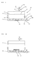
Fig. 9 is a schematic cross-sectional view of a conventional solar cell. - A first embodiment of the present invention is a method for manufacturing a solar cell module in which a solar cell having a surface electrode to which a tab lead is connected with an adhesive is sealed with a resin using a vacuum laminator.
- The vacuum laminator used in the present invention includes a first chamber and a second chamber partitioned by a flexible sheet. The inner pressures of these chambers can be controlled independently, and a heating stage for heating is provided in the second chamber. An example of such a vacuum laminator will be described in more detail with reference to
Fig. 1 . -
Fig. 1 shows thevacuum laminator 10 before use, and thevacuum laminator 10 includes anupper unit 11 and alower unit 12. These units are separably integrated through a sealingmember 13 such as an O-ring. Aflexible sheet 14 of, for example, silicon rubber is provided in theupper unit 11, and thevacuum laminator 10 is partitioned into afirst chamber 15 and asecond chamber 16 by theflexible sheet 14. To prevent a molten sealing resin such as EVA from adhering to the surface of theflexible sheet 14 that faces the inside of thesecond chamber 16, a thin glass cloth-reinforced Teflon (registered trademark) sheet may be disposed on that surface. -
Pipes upper unit 11 and thelower unit 12, respectively, so that the inner pressures of the respective chambers can be controlled independently, i.e., the pressures can be reduced and increased by vacuum pumps or compressors and the chambers can be open to the air. Thepipe 17 is branched into twodirections valve 19, and thepipe 18 is branched into twodirections valve 20. Aheating stage 21 is provided in thelower unit 12. - This vacuum laminator 10 is used as shown in, for example,
Figs. 2A to 2E . - First, as shown in
Fig. 2A , theupper unit 11 and thelower unit 12 are separated from each other, and astacked product 22 to be thermo-compression bonded is placed on thestage 21. - Next, as shown in
Fig. 2B , theupper unit 11 and thelower unit 12 are separably integrated through the sealingmember 13. Then vacuum pumps (not shown) are connected to thepipes first chamber 15 and thesecond chamber 16 to a high vacuum. - While the
second chamber 16 is maintained at a high vacuum, the switchingvalve 19 is switched to introduce air to thefirst chamber 15 through thepipe 17b, as shown inFig. 2C . Theflexible sheet 14 is thereby expanded toward thesecond chamber 16. Therefore, the stackedproduct 22 is pressed by theflexible sheet 14 while being heated by thestage 21. - Next, as shown in
Fig. 2D , the switchingvalve 20 is switched to introduce air to thesecond chamber 16 through thepipe 18b. Then theflexible sheet 14 is pushed back toward thefirst chamber 15, and the internal pressures of thefirst chamber 15 and thesecond chamber 16 eventually become the same. - Finally, as shown in
Fig. 2E , theupper unit 11 and thelower unit 12 are separated from each other, and the thermo-compression bonded stackedproduct 22 is removed from theheating stage 21. The operation cycle of thevacuum laminator 10 is thereby completed, and the process returns toFig. 2A . - When the stacked
product 22 is a stack in which a conductive adhesive film is sandwiched between the surface electrode of a solar cell and a tab lead and a sealing resin layer is disposed over the entire surface of the solar cell, the operations shown inFigs. 2A to 2D allow the conductive connection between the surface electrode and the tab lead and the resin-sealing of the conductive connection portion to be achieved simultaneously. - The vacuum laminator used in the present invention has been described above. However, the usable vacuum laminator is not limited to the vacuum laminator including the
upper unit 11 and thelower unit 12 shown inFig. 1 .
A vacuum laminator including one casing divided into two chambers and configured such that a stacked product is placed and removed through an open-close door may also be used. The first and second chambers may be designed such that compressed air is introduced to the first chamber to perform pressurization at a pressure equal to or higher than atmospheric pressure. In this case, the air inside the second chamber may be simply discharged without reducing the pressure inside the second chamber. - In the first embodiment of the present invention, as shown in
Fig. 3A , asolar cell 32 having asurface electrode 31 formed thereon is stacked on theheating stage 21 in thesecond chamber 16 of the vacuum laminator partitioned from thefirst chamber 15 by theflexible sheet 14. Then, an adhesive 33 on thesurface electrode 31, atab lead 34 on the adhesive 33, a pressurizingfilm 35 on thetab lead 34, a sealingresin layer 36 on the pressurizingfilm 35, and a moisture-proof back sheet 37 or a glass plate (not shown) on the sealingresin layer 36 are sequentially stacked. - Next, as shown in
Fig. 3B , the internal pressure of the first chamber of the vacuum laminator is increased relative to the internal pressure of the second chamber to press theflexible sheet 14 against the moisture-proof back sheet 37 or the glass plate, and simultaneously thesolar cell 32 is heated by theheating stage 21. Thesurface electrode 31 of thesolar cell 32 is thereby connected to thetab lead 34, and thesolar cell 32 is resin-sealed with the sealingresin layer 36. Asolar cell module 30 can be obtained in this manner (Fig. 3C ). - Preferred examples of the operation for increasing the internal pressure of the
first chamber 15 of the vacuum laminator relative to the internal pressure of thesecond chamber 16 include an operation including reducing the internal pressures of thefirst chamber 15 and thesecond chamber 16 and then opening thefirst chamber 15 to the air while the reduced pressure inside thesecond chamber 16 is maintained. - Any of the known adhesives, such as conductive adhesive pastes (CPs), conductive adhesive films (CFs), anisotropic conductive pastes (ACPs), anisotropic conductive adhesive films (ACFs), non-conductive adhesive pastes (NCPs), and non-conductive adhesive films (NCFs), used when electronic components are mounted on a solar cell can be used as the adhesive 33. A thermosetting adhesive is preferably used.
- Any of resin films, synthetic paper sheets, nonwoven fabrics, and the like that have thicknesses of 5 to 500 µm and exhibit dimensional stability even during heating and pressurization by the vacuum laminator can be used as the pressurizing
film 35. Any of polyamide, polyimide, polyester, and the like can be used as the material that forms the pressurizingfilm 35. Preferably, the glass transition temperature of the pressurizingfilm 35 is higher than the laminating temperature of the sealingresin layer 36. Specifically, the glass transition temperature is at least 10°C higher than the laminating temperature. - Preferably, the circumferential edges of the pressurizing
film 35 are resin-sealed with the sealingresin layer 36. With this structure, a pressurizing film having no adhesive properties can be used as the pressurizingfilm 35. - A sealing resin layer formed of any of the known liquid- and paste-like sealing resin compositions can be used as the sealing
resin layer 36, and a sealing resin sheet formed into a sheet shape is particularly preferably used. Specifically, a thermoplastic ethylene/vinyl acetate copolymer sheet having good sealing and adhesive properties can be preferably used. Generally, the sealingresin layer 36 flows when heated during resin-sealing and covers areas to be sealed. When the sealingresin layer 36 contains a curable component, good resin-sealing can be achieved by curing the sealingresin layer 36 after it flows. - The
solar cell 32 having thesurface electrode 31 is a solar cell required to be bonded to a tab lead and to be sealed with a resin. Examples of such a solar cell include crystalline solar cells using crystalline photoelectric conversion elements and thin-film solar cells using thin-film photoelectric conversion elements. A surface electrode may also be provided on the rear surface of the solar cell. In such a case, a solar cell unit composed of a plurality of solar cells can be formed (seeFig. 8 in Patent Literature 1 andFig. 1 in Patent Literature 2). Any of the known materials can be used as the material of the photoelectric conversion element of the solar cell. Examples of such materials include single crystalline silicon, polycrystalline silicon, amorphous silicon, single crystalline compounds such as GaAs-based compounds, and polycrystalline compounds such as CdS and CdTe. - In a conventional solar cell module, the tab leads are used as inner leads for connecting the solar cells to each other or outer leads for outputting power. Solder-coated copper foil ribbons may be preferably used as the tab leads.
- In the first embodiment of the present invention, the moisture-
proof back sheet 37 or the glass plate is stacked on the sealingresin layer 36. The moisture-proof back sheet 37 or the glass plate used can be appropriately selected from those used in conventional solar cell modules. - A second embodiment of the present invention in which no pressurizing film is used will next be described.
- The second embodiment of the present invention is a manufacturing method including sealing, with a resin using a vacuum laminator, a solar cell having a surface electrode to which a tab lead is connected through an isotropic or anisotropic conductive adhesive film (CF or ACF).
- In the second embodiment, a conductive
adhesive film 41 used includes a thermosettingresin film base 42 andconductive particles 43 having a particle diameter larger than the thickness of the base and held therein, as shown inFig. 4A . Theconductive particles 43 protrude from at least one side of the thermosettingresin film base 42. Since theconductive particles 43 protrude from the thermosettingresin film base 42 as described above, the spaces between theconductive particles 43 accommodate theconductive particles 43 that have been crushed. Therefore, the conductive particles in the conductive adhesive film can be sufficiently crushed to establish conductive connection without using the pressurizing film used in the first embodiment. A thermosetting resin thin film (not shown) may be formed on the surface of each protrudingconductive particle 43 within a range in which the effect of the present invention is not impaired. - In this second embodiment, no pressurizing film is used. Therefore, the second embodiment is advantageous in that, even when it is applied to the light-receiving side, a reduction in light-receiving efficiency due to the use of a pressurizing film is not required to be taken into consideration.
- In the second embodiment, as shown in
Fig. 4B , asolar cell 32 having asurface electrode 31 formed thereon is first stacked on theheating stage 21 in thesecond chamber 16 of the vacuum laminator partitioned from thefirst chamber 15 by theflexible sheet 14. Then a conductiveadhesive film 41 on thesurface electrode 31, atab lead 34 on the conductiveadhesive film 41, a sealingresin layer 36 on thetab lead 34, and a moisture-proof back sheet 37 or a glass plate (not shown) on the sealingresin layer 36 are sequentially stacked. Note that the conductiveadhesive film 41 is stacked on thesurface electrode 31 such that the surface of the conductiveadhesive film 41 from which the conductive particles protrude faces thesurface electrode 31. - Next, as shown in
Fig. 4C , the internal pressure of the first chamber of the vacuum laminator is increased relative to the internal pressure of the second chamber to press theflexible sheet 14 against the moisture-proof back sheet 37 or the glass plate, and simultaneously thesolar cell 32 is heated by theheating stage 21. Thesurface electrode 31 of thesolar cell 32 is thereby conductively connected to thetab lead 34, and the connection area of thesolar cell 32 is resin-sealed with the sealingresin layer 36. Asolar cell module 40 can be obtained in this manner (Fig. 4D ). - "The operation for increasing the internal pressure of the first chamber of the vacuum laminator relative to the internal pressure of the second chamber," "the sealing resin sheet," "the solar cell having the surface electrode," "the moisture-proof back sheet," and "the glass plate" are as described in the first embodiment of the present invention.
- A description will next be given of a third embodiment of the present invention that uses no pressurizing film, which is different from the second embodiment.
- The third embodiment of the present invention is a method for manufacturing a solar cell module in which a solar cell having a surface electrode to which a tab lead is connected is sealed with a resin using a vacuum laminator. First, a description will be given of the case in which convex portions are formed on the tab lead.
- In the third embodiment, as shown in
Fig. 5A , thetab lead 51 used includes ametal substrate 52 and a thermosetting adhesive layer 53 formed on one side thereof, andconvex portions 52a of themetal substrate 52 protrude from the thermosetting adhesive layer 53 so as to be connectable to the surface electrode. Since theconvex portions 52a of themetal substrate 52 protrude from the thermosetting adhesive layer 53 as described above, the spaces between theconvex portions 52a accommodate theconvex portions 52a that have been crushed. Therefore, conductive connection can be established without using the pressurizing film used in the first embodiment. A thermosetting adhesive thin film (not shown) may be formed on the surface of eachconvex portion 52a within a range in which the effect of the present invention is not impaired. - In the third embodiment, as shown in
Fig. 5B , asolar cell 32 having asurface electrode 31 formed thereon is first stacked on theheating stage 21 in thesecond chamber 16 of the vacuum laminator partitioned from thefirst chamber 15 by theflexible sheet 14. Then thetab lead 51 on thesurface electrode 31, a sealingresin layer 36 on thetab lead 51, a moisture-proof back sheet 37 or a glass plate (not shown) on the sealingresin layer 36 are sequentially stacked. Note that thetab lead 51 is stacked on thesurface electrode 31 such that the surface of thetab lead 51 from which theconvex portions 52a of themetal substrate 52 protrude faces thesurface electrode 31. - Next, as shown in
Fig. 5C , the internal pressure of the first chamber of the vacuum laminator is increased relative to the internal pressure of the second chamber to press theflexible sheet 14 against the moisture-proof back sheet 37 or the glass plate, and simultaneously thesolar cell 32 is heated by theheating stage 21. Thesurface electrode 31 of thesolar cell 32 is thereby conductively connected to thetab lead 51, and the connection area of thesolar cell 32 is resin-sealed with the sealingresin layer 36. Asolar cell module 50 can be obtained in this manner (Fig. 5D ). - In this third embodiment, no pressurizing film is used. Therefore, the third embodiment is advantageous in that, even when it is applied to the light-receiving side, a reduction in light-receiving efficiency due to the use of a pressurizing film is not required to be taken into consideration.
- "The operation for increasing the internal pressure of the first chamber of the vacuum laminator relative to the internal pressure of the second chamber," "the sealing resin sheet," "the solar cell having the surface electrode," "the moisture-proof back sheet," and "the glass plate" are as described in the first embodiment of the present invention.
- A description will next be given of the third embodiment of the present invention when the convex portions are not formed on the tab lead but are formed on the surface electrode.
- More specifically, the third embodiment of the present invention in which the convex portions are formed on the surface electrode is a method for manufacturing a solar cell module in which a solar cell having a surface electrode to which a tab lead is connected is sealed with a resin using a vacuum laminator. The method is characterized by:
- using as the tab lead one including a metal substrate and a thermosetting adhesive layer formed on one side of the metal substrate, wherein
- the surface electrode has a convex portion that is formed in a region to be connected to the tab lead;
- using as the vacuum laminator one including a first chamber and a second chamber partitioned by a flexible sheet, wherein the internal pressure of the first chamber and the internal pressure of the second chamber can be controlled independently and a heating stage for heating is provided in the second chamber;
- sequentially stacking the solar cell having the surface electrode formed thereon on the heating stage in the second chamber of the vacuum laminator, the tab lead on the surface electrode, a sealing resin layer on the tab lead, and a moisture-proof back sheet or a glass plate on the sealing resin layer; and
- while the internal pressure of the first chamber of the vacuum laminator is increased relative to the internal pressure of the second chamber to press the flexible sheet against the moisture-proof back sheet or the glass plate, heating the solar cell by the heating stage to thereby connect the convex portion of the surface electrode of the solar cell to the tab lead and to resin-seal the solar cell with the sealing resin layer, whereby the solar cell module is obtained.
- In this embodiment, no particular limitation is imposed on the method of forming the convex portions on the surface electrode of the solar cell. Any of a plating method, a photolithographic method, a press method using a mold, and the like can be used.
- In each of the above first to third embodiments of the present invention, the solar cell module manufacturing method in which a tab lead is connected to one side of a solar cell and simultaneously the solar cell is sealed with a resin has been described in detail, but the present invention is not limited thereto. For example, a method in which tab leads for series connection are connected to opposite sides of solar cells that use crystalline photoelectric conversion elements and then the solar cells are sealed with a resin as shown in
Fig. 8A (seeFig. 1 in Japanese Patent Application Laid-Open No.2008-300403 Fig. 8B (seeFigs. 3 and4 in Japanese Patent Application Laid-Open No.2000-340811 - Specifically, in the case of
Fig. 8A , a plurality of solar cells are prepared. Then a second end of atab lead 34 having a first end temporarily applied to the rear-side electrode (not shown) of asolar cell 32a is temporarily applied to the front-side electrode (not shown) of an adjacent solar cell 32b through an adhesive under pressure at room temperature or at a low temperature (about 30 to 120°C). The formation of such a temporarily applied pattern is performed for the plurality of solar cells to obtain asolar cell unit 100. By replacing thesolar cell 32 shown in any ofFigs. 3A to 3C ,Figs. 4B to 4D , andFigs. 5B to 5D with thissolar cell unit 100, a solar cell module including the solar cell unit composed of a plurality of solar cells can be obtained. - In the case of
Fig. 8B , thin-filmsolar cells 32 including thin-film photoelectric conversion elements are arranged in series in a plane direction on asubstrate 38. Tab leads 34 for outputting power are temporarily applied to the surface electrodes (not shown) of an outermost solar cell 32c and another outermostsolar cell 32d through an adhesive under pressure at room temperature or at a low temperature (about 30 to 120°C) to obtain asolar cell unit 100. By replacing thesolar cell 32 shown in any ofFigs. 3A to 3C ,Figs. 4B to 4D , andFigs. 5B to 5D with thissolar cell unit 100, a solar cell module including the solar cell unit composed of a plurality of solar cells can be obtained. - In the present invention, when the tab lead and the pressurizing film are sequentially stacked on the adhesive, a pressurizing film having a lead wire pre-stacked thereon may be used.
- The present invention will next be specifically described by way of Examples.
- The first embodiment of the present invention was implemented using the following materials as substitutes for the materials of the solar cell.
-
- Glass substrate: 30 mm x 80 mm x 0.7 mm thick
- Tab lead: a lead obtained by dip-plating both sides of a Cu wire of 2 mm width x 0.15 mm thick with Pb-free solder made of Sn-Ag-Cu to a thickness of 20 µm
- Conductive adhesive film: a film obtained by mixing 50 parts by mass of an epoxy resin (EP828, Japan Epoxy Resin Co., Ltd.), 20 parts by mass of a phenoxy resin (YP50, Tohto Kasei Co., Ltd.), 20 parts by mass of a curing agent (HX3941, Asahi Kasei Chemicals Corporation), and 10 parts by mass of conductive particles (AUL, Sekisui Chemical Co., Ltd.) having an average particle diameter of 10 µm, adding toluene to the mixture such that the concentration of solids was 30%, and applying the resultant mixture to a copper foil using a roll coater to a dry thickness of 25 µm, and drying the product in an oven at 80°C
- Pressurizing film: a polyimide film of 30 mm x 40 mm x 85 µm (thick)
- Sealing resin sheet: an ethylene-vinyl acetate copolymer sheet of 30 mm x 80 mm x 0.5 mm
- Moisture-proof back sheet: a polyethylene terephthalate film (35 µm thick) used as a substitute for the moisture-proof back sheet
- The glass substrate was placed on the heating stage in the second chamber of the vacuum laminator shown in
Fig. 1 . The conductive adhesive film (width: 2 mm, length: 5 mm, and thickness: 0.05 mm) was placed on the surface of the glass substrate, and the tab lead, the pressurizing film, the sealing resin sheet, and the moisture-proof back sheet were placed on the conductive adhesive film. While the heating stage was maintained at 150°C, the pressures of the first and second chambers were reduced to 133 Pa. Then while the reduced pressure of the second chamber was maintained, air was introduced to the first chamber to bring it to atmospheric pressure. After this state was maintained for 5 minutes, air was introduced to the second chamber to bring it to atmospheric pressure. The obtained stacked product was observed under a microscope from the rear side (the glass surface side), and the conductive particles were found to be crushed (Fig. 6A ). - A stacked product was obtained by the same procedure as in Example 1 except that a conductive adhesive paste obtained by mixing 50 parts by mass of an epoxy resin (EP828, Japan Epoxy Resin Co., Ltd.), 40 parts by mass of a curing agent (HX3941, Asahi Kasei Chemicals Corporation), and 10 parts by mass of conductive particles (AUL, Sekisui Chemical Co., Ltd.) having an average particle diameter of 10 µm was used instead of the conductive adhesive film and that the conductive adhesive paste was applied to the surface of the glass substrate to a width of 2 mm, a length of 5 mm, and a thickness of 0.05mm. The obtained stacked product was observed under a microscope from the rear side (the glass surface side), and the conductive particles were found to be crushed.
- A stacked product was obtained by repeating the same procedure as in Example 1 except that the pressurizing film was not used. The obtained stacked product was observed under a microscope from the rear side (the glass surface side), and crushed conductive particles were not found (
Fig. 6B ) . - The second embodiment of the present invention was implemented using the following materials as substitutes for the materials of the solar cell.
-
- Glass substrate with ITO: 30 mm x 80 mm x 0.7 mm thick
- Tab lead: a Cu wire of 2 mm width x 0.12 mm thick
- Conductive adhesive film: a film obtained by mixing 50 parts by mass of an epoxy resin (EP828, Japan Epoxy Resin Co., Ltd.), 20 parts by mass of a phenoxy resin (YP50, Tohto Kasei Co., Ltd.), 20 parts by mass of a curing agent (HX3941, Asahi Kasei Chemicals Corporation), and 10 parts by mass of conductive particles (AUL, Sekisui Chemical Co., Ltd.) having an average particle diameter of 10 µm, adding toluene to the mixture such that the concentration of solids was 30%, and applying the resultant mixture to a copper foil using a roll coater to a thickness of 10 µm, and drying the product in an oven at 80°C (the thickness of the resin layer: 3 µm)
- Sealing resin sheet: an ethylene-vinyl acetate copolymer sheet of 30 mm x 80 mm x 0.5 mm
- Moisture-proof back sheet: a polyethylene terephthalate film (35 µm thick) used as a substitute for the moisture-proof back sheet
- The glass substrate with ITO was placed on the heating stage in the second chamber of the vacuum laminator shown in
Fig. 1 . The tab lead was temporarily applied to the glass substrate with the conductive adhesive film (of the type in which conductive particles protruded from the surface of the film) facing the ITO electrode on the surface of the glass substrate, and the sealing resin sheet and the polyethylene terephthalate film with a thickness of 80 µm were placed thereon. While the heating stage was maintained at 150°C, the pressures of the first and second chambers were reduced to 133 Pa. Then while the reduced pressure of the second chamber was maintained, air was introduced to the first chamber to bring it to atmospheric pressure. After this state was maintained for 5 minutes, air was introduced to the second chamber to bring it to atmospheric pressure. The obtained stacked product was observed under a microscope from the rear side (the glass surface side), and the conductive particles were found to be crushed (Fig. 7A ). The resistance value was measured and found to be 5 mΩ. - A stacked product was obtained by repeating the same procedure as in Example 2 except that the conductive adhesive film produced in Example 1 was used. The obtained stacked product was observed under a microscope from the rear side (the glass surface side), and crushed conductive particles were not found (
Fig. 7B ). The measurement of resistance value was attempted, and the resistance value could not be measured. Electric connection was not established. - The third embodiment of the present invention was implemented using the following materials as substitutes for the materials of the solar cell.
-
- Glass substrate with ITO: 30 mm x 80 mm x 0.7 mm thick Tab lead: a Cu wire of 2 mm width x 0.12 mm thick in which convex protrusions (height: 10 µm) were formed on one side at a density of about 50,000 protrusions/mm2 using the matte treatment technique
- Thermosetting adhesive layer: an adhesive layer obtained by applying, to the surface of the tab lead having the convex protrusions formed thereon, a thermosetting adhesive (20 parts by mass of a phenoxy resin (YP50, Tohto Kasei Co., Ltd.), 50 parts by mass of an epoxy resin (EP828, Japan Epoxy Resin Co., Ltd.), and 20 parts by mass of a curing agent (HX3941, Asahi Kasei Chemicals Corporation)) to a thickness of 7 µm by the application-drying method
- Sealing resin sheet: an ethylene-vinyl acetate copolymer sheet of 30 mm x 80 mm x 0.5 mm
- Moisture-proof back sheet: a polyethylene terephthalate film (35 µm thick) used as a substitute for the moisture-proof back sheet
- The glass substrate was placed on the heating stage in the second chamber of the vacuum laminator shown in
Fig. 1 . The tab lead was temporarily applied to the glass substrate such that the convex protrusions of the tab lead faced the ITO electrode on the surface of the glass substrate, and the sealing resin sheet and the polyethylene terephthalate film with a thickness of 80 µm were placed thereon. While the heating stage was maintained at 150°C, the pressures of the first and second chambers were reduced to 133 Pa. Then while the reduced pressure of the second chamber was maintained, air was introduced to the first chamber to bring it to atmospheric pressure. After this state was maintained for 5 minutes, air was introduced to the second chamber to bring it to atmospheric pressure. The obtained stacked product was observed under a microscope from the rear side (the glass surface side), and the convex protrusions were found to be crushed. The resistance value was measured and found to be 5 mΩ. - A stacked product was obtained by repeating the same procedure as in Example 2 except that a flat tab lead having no convex protrusions formed thereon was used. The resistance value of the obtained stacked product was measured and found to be open.
- Each of the manufacturing methods of the present invention is used to manufacture a solar cell module in which a solar cell having a surface electrode to which a tab lead is connected is sealed with a resin. In each manufacturing method, the tab lead connecting step of connecting the surface electrode to the tab lead and the resin sealing step of sealing the solar cell with a sealing resin can be performed simultaneously at a relatively low temperature, i.e., the temperature for the resin sealing step. Therefore, the manufacturing method is useful for the manufacturing of a solar cell and a solar cell unit including a combination of solar cells. Specifically, the manufacturing method is useful for a crystalline solar cell when an inner lead is connected to a bus bar electrode formed by screen printing using silver paste and useful for a thin-film solar cell when a surface electrode is connected to an outer lead.
-
- 10
- vacuum laminator
- 11
- upper unit
- 12
- lower unit
- 13
- sealing member
- 14
- flexible sheet
- 15
- first chamber
- 16
- second chamber
- 17, 17a, 17b, 18, 18a, 18b
- pipe
- 19, 20
- switching valve
- 21
- heating stage
- 22
- stacked product
- 30, 40, 50
- solar cell module
- 31
- surface electrode
- 32, 32a, 32b, 32c, 32d
- solar cell
- 33
- adhesive
- 34, 51
- tab lead
- 35
- pressurizing film
- 36
- sealing resin layer
- 37
- moisture-proof back sheet
- 38
- substrate
- 41
- conductive adhesive film
- 42
- thermosetting resin film base
- 43
- conductive particle
- 52
- metal substrate
- 52a
- convex portion
- 53
- thermosetting adhesive layer
- 100
- solar cell unit
Claims (20)
- A method for manufacturing a solar cell module in which a solar cell having a surface electrode to which a tab lead is connected with an adhesive is sealed with a resin using a vacuum laminator, the method comprising:using as the vacuum laminator one including a first chamber and a second chamber partitioned by a flexible sheet, wherein an internal pressure of the first chamber and an internal pressure of the second chamber can be controlled independently and a heating stage for heating is provided in the second chamber;sequentially stacking the solar cell having the surface electrode formed thereon on the heating stage in the second chamber of the vacuum laminator, the adhesive on the surface electrode, the tab lead on the adhesive, a pressurizing film on the tab lead, a sealing resin layer on the pressurizing film, and a moisture-proof back sheet or a glass plate on the sealing resin layer; andwhile the internal pressure of the first chamber of the vacuum laminator is increased relative to the internal pressure of the second chamber to press the flexible sheet against the moisture-proof back sheet or the glass plate, heating the solar cell by the heating stage to thereby connect the surface electrode of the solar cell to the tab lead and to resin-seal the solar cell with the sealing resin layer, whereby the solar cell module is obtained.
- The manufacturing method according to claim 1,
wherein an operation for increasing the internal pressure of the first chamber of the vacuum laminator relative to the internal pressure of the second chamber includes reducing the internal pressures of the first chamber and the second chamber and then opening the first chamber to atmosphere while the reduced pressure inside the second chamber is maintained. - The manufacturing method according to claim 1,
wherein the adhesive is a conductive adhesive film. - The manufacturing method according to any of claims 1 to 3, wherein circumferential edges of the pressurizing film are resin-sealed with the sealing resin layer.
- The manufacturing method according to any of claims 1 to 4, wherein the sealing resin layer is made from an ethylene/vinyl acetate copolymer sheet.
- The manufacturing method according to any of claims 1 to 5, wherein the solar cell is a thin-film solar cell or a crystalline solar cell in which the surface electrode and the tab lead are connected to each other with a conductive adhesive film.
- The manufacturing method according to any of claims 1 to 6, wherein the solar cell is a component of a solar cell unit including a plurality of solar cells connected together.
- The manufacturing method according to any of claims 1 to 7, wherein, when the tab lead and the pressurizing film are sequentially stacked on the adhesive, a pressurizing film having a lead wire that has been stacked thereon in advance is used.
- A method for manufacturing a solar cell module in which a solar cell having a surface electrode to which a tab lead is connected through a conductive adhesive film is sealed with a resin using a vacuum laminator, the method comprising:using as the conductive adhesive film one including a thermosetting resin film base and conductive particles that have a diameter larger than a thickness of the thermosetting resin film base and are held therein, the conductive particles protruding from at least one side of the thermosetting resin film base;using as the vacuum laminator one including a first chamber and a second chamber partitioned by a flexible sheet, wherein an internal pressure of the first chamber and an internal pressure of the second chamber can be controlled independently and a heating stage for heating is provided in the second chamber;sequentially stacking the solar cell having the surface electrode formed thereon on the heating stage in the second chamber of the vacuum laminator, the conductive adhesive film on the surface electrode, the tab lead on the conductive adhesive film, a sealing resin layer on the tab lead, and a moisture-proof back sheet or a glass plate on the sealing resin layer, provided that the conductive adhesive film is stacked on the surface electrode such that the surface of the conductive adhesive film from which the conductive particles protrude faces the tab lead or the surface electrode; andwhile the internal pressure of the first chamber of the vacuum laminator is increased relative to the internal pressure of the second chamber to press the flexible sheet against the moisture-proof back sheet or the glass plate, heating the solar cell by the heating stage to thereby conductively connect the surface electrode of the solar cell to the tab lead and to resin-seal the solar cell with the sealing resin layer, whereby the solar cell module is obtained.
- The manufacturing method according to claim 9,
wherein an operation for increasing the internal pressure of the first chamber of the vacuum laminator relative to the internal pressure of the second chamber includes reducing the internal pressures of the first chamber and the first chamber and then opening the second chamber to atmosphere while the reduced pressure inside the second chamber is maintained. - The manufacturing method according to any of claims 9 and 10, wherein the sealing resin layer is made from an ethylene/vinyl acetate copolymer sheet.
- The manufacturing method according to any of claims 9 to 11, wherein the solar cell is a thin-film solar cell or a crystalline solar cell in which the surface electrode and the tab lead are connected to each other with a conductive adhesive film.
- The manufacturing method according to any of claims 9 to 12, wherein, when the tab lead and the pressurizing film are sequentially stacked on the adhesive, a pressurizing film having a lead wire that has been stacked thereon in advance is used.
- The manufacturing method according to any of claims 9 to 13, wherein the solar cell is a component of a solar cell unit including a plurality of solar cells connected together.
- A method for manufacturing a solar cell module in which a solar cell having a surface electrode to which a tab lead is connected is sealed with a resin using a vacuum laminator, the method comprising:using as the tab lead one including a metal substrate and a thermosetting adhesive layer formed on one side of the metal substrate, the metal substrate having a convex portion that protrudes from the thermosetting adhesive layer so as to be connectable to the surface electrode, or as the tab lead one including a metal substrate and a thermosetting adhesive layer formed on one side of the metal substrate, the surface electrode having a convex portion that is formed in a region to be connected to the tab lead;using as the vacuum laminator one including a first chamber and a second chamber partitioned by a flexible sheet, wherein an internal pressure of the first chamber and an internal pressure of the second chamber can be controlled independently and a heating stage for heating is provided in the second chamber;sequentially stacking the solar cell having the surface electrode formed thereon on the heating stage in the second chamber of the vacuum laminator, the tab lead on the surface electrode, a sealing resin layer on the tab lead, and a moisture-proof back sheet or a glass plate on the sealing resin layer, provided that the tab lead including the metal substrate having the convex portion protruding from the thermosetting adhesive layer is stacked on the surface electrode such that the surface of the tab lead from which the convex portion of the metal substrate protrudes faces the surface electrode; andwhile the internal pressure of the first chamber of the vacuum laminator is increased relative to the internal pressure of the second chamber to press the flexible sheet against the moisture-proof back sheet or the glass plate, heating the solar cell by the heating stage to thereby connect the surface electrode of the solar cell to the convex portion of the tab lead and to resin-seal the solar cell with the sealing resin layer, whereby the solar cell module is obtained.
- The manufacturing method according to claim 15, wherein an operation for increasing the internal pressure of the first chamber of the vacuum laminator relative to the internal pressure of the second chamber includes reducing the internal pressures of the first chamber and the second chamber and then opening the first chamber to atmosphere while the reduced pressure inside the second chamber is maintained.
- The manufacturing method according to claim 15 or 16, wherein the sealing resin layer is made from an ethylene/vinyl acetate copolymer sheet.
- The manufacturing method according to any of claims 15 to 17, wherein the solar cell is a thin-film solar cell or a crystalline solar cell in which the surface electrode and the tab lead are connected to each other with a conductive adhesive film.
- The manufacturing method according to any of claims 15 to 18, wherein, when the tab lead and the pressurizing film are sequentially stacked on the adhesive, a pressurizing film having a lead wire that has been stacked thereon in advance is used.
- The manufacturing method according to any of claims 15 to 19, wherein the solar cell is a component of a solar cell unit including a plurality of solar cells connected together.
Applications Claiming Priority (2)
| Application Number | Priority Date | Filing Date | Title |
|---|---|---|---|
| JP2009134055A JP5229497B2 (en) | 2009-06-03 | 2009-06-03 | Manufacturing method of solar cell module |
| PCT/JP2010/058177 WO2010140455A1 (en) | 2009-06-03 | 2010-05-14 | Method for manufacturing solar cell modules |
Publications (2)
| Publication Number | Publication Date |
|---|---|
| EP2439781A1 true EP2439781A1 (en) | 2012-04-11 |
| EP2439781A4 EP2439781A4 (en) | 2013-07-24 |
Family
ID=43297592
Family Applications (1)
| Application Number | Title | Priority Date | Filing Date |
|---|---|---|---|
| EP10783239.6A Withdrawn EP2439781A4 (en) | 2009-06-03 | 2010-05-14 | METHOD FOR MANUFACTURING SOLAR CELL MODULES |
Country Status (6)
| Country | Link |
|---|---|
| US (1) | US8415195B2 (en) |
| EP (1) | EP2439781A4 (en) |
| JP (1) | JP5229497B2 (en) |
| KR (1) | KR101322974B1 (en) |
| CN (1) | CN102460726B (en) |
| WO (1) | WO2010140455A1 (en) |
Families Citing this family (11)
| Publication number | Priority date | Publication date | Assignee | Title |
|---|---|---|---|---|
| JP2012134458A (en) * | 2010-12-01 | 2012-07-12 | Sony Chemical & Information Device Corp | Thin film solar cell module and manufacturing method of the same |
| JP2012204388A (en) * | 2011-03-23 | 2012-10-22 | Sony Chemical & Information Device Corp | Solar cell module, manufacturing method of solar cell module, reel with tab line wound thereabout |
| WO2013018152A1 (en) * | 2011-07-29 | 2013-02-07 | 日立化成工業株式会社 | Adhesive composition, film-like adhesive and circuit connecting material using same adhesive composition, connection structure for circuit member and manufacturing method for same |
| WO2013030993A1 (en) * | 2011-08-31 | 2013-03-07 | 三洋電機株式会社 | Solar cell module |
| CN102496477A (en) * | 2011-11-18 | 2012-06-13 | 中国科学院等离子体物理研究所 | Dye sensitization solar cell sealing method and device thereof |
| JP5889701B2 (en) | 2012-04-06 | 2016-03-22 | デクセリアルズ株式会社 | Crystalline solar cell module and manufacturing method thereof |
| CN103022250A (en) * | 2012-12-14 | 2013-04-03 | 秦皇岛瑞晶太阳能科技有限公司 | Positive pressure encapsulation device of building integrated photovoltaics (BIPV) solar energy component |
| CN107757051B (en) * | 2016-08-16 | 2024-05-14 | 阿特斯阳光电力集团股份有限公司 | Photovoltaic module laminating equipment and laminating method |
| CN110696471B (en) * | 2018-06-22 | 2023-05-26 | 紫石能源有限公司 | A kind of solar module lamination method |
| CN110931581A (en) * | 2018-09-18 | 2020-03-27 | 汉能移动能源控股集团有限公司 | A kind of solar cell and its packaging method |
| JP2024122434A (en) | 2023-02-28 | 2024-09-09 | パナソニックホールディングス株式会社 | Manufacturing method of solar cell string |
Family Cites Families (15)
| Publication number | Priority date | Publication date | Assignee | Title |
|---|---|---|---|---|
| JP3744126B2 (en) * | 1997-06-23 | 2006-02-08 | 富士電機ホールディングス株式会社 | Solar cell module external lead connection structure |
| US5951786A (en) * | 1997-12-19 | 1999-09-14 | Sandia Corporation | Laminated photovoltaic modules using back-contact solar cells |
| JP3619390B2 (en) | 1999-05-27 | 2005-02-09 | シャープ株式会社 | Manufacturing method of integrated thin film solar cell |
| JP3821661B2 (en) | 2001-04-23 | 2006-09-13 | シャープ株式会社 | Solar cell module and manufacturing method thereof |
| JP2004179261A (en) * | 2002-11-25 | 2004-06-24 | Kyocera Corp | Apparatus and method for manufacturing solar cell module |
| JP2004200518A (en) * | 2002-12-19 | 2004-07-15 | Kyocera Corp | Apparatus and method for manufacturing solar cell module |
| JP2004356349A (en) | 2003-05-28 | 2004-12-16 | Kyocera Corp | Method of manufacturing solar cell module |
| JPWO2005086557A1 (en) * | 2004-03-03 | 2008-01-24 | 株式会社ブリヂストン | Electromagnetic shielding light transmitting window material, display panel, and solar cell module manufacturing method |
| KR100711566B1 (en) * | 2006-09-08 | 2007-04-27 | 해성쏠라(주) | Manufacturing method of solar cell module for automobile sunroof |
| JP4294048B2 (en) * | 2006-11-29 | 2009-07-08 | 三洋電機株式会社 | Solar cell module |
| JP5063099B2 (en) * | 2006-12-13 | 2012-10-31 | 三洋電機株式会社 | Solar cell module and method for manufacturing solar cell module |
| JP4429306B2 (en) * | 2006-12-25 | 2010-03-10 | 三洋電機株式会社 | Solar cell and solar cell module |
| JP5052154B2 (en) * | 2007-02-16 | 2012-10-17 | 三洋電機株式会社 | Manufacturing method of solar cell module |
| JP5116363B2 (en) | 2007-05-29 | 2013-01-09 | デクセリアルズ株式会社 | Manufacturing method of conductor wire |
| JP5380810B2 (en) * | 2007-09-28 | 2014-01-08 | 三洋電機株式会社 | Solar cell module |
-
2009
- 2009-06-03 JP JP2009134055A patent/JP5229497B2/en active Active
-
2010
- 2010-05-14 KR KR1020117028933A patent/KR101322974B1/en active Active
- 2010-05-14 CN CN201080025146.1A patent/CN102460726B/en active Active
- 2010-05-14 US US13/319,396 patent/US8415195B2/en active Active
- 2010-05-14 EP EP10783239.6A patent/EP2439781A4/en not_active Withdrawn
- 2010-05-14 WO PCT/JP2010/058177 patent/WO2010140455A1/en not_active Ceased
Also Published As
| Publication number | Publication date |
|---|---|
| CN102460726A (en) | 2012-05-16 |
| US8415195B2 (en) | 2013-04-09 |
| WO2010140455A1 (en) | 2010-12-09 |
| KR101322974B1 (en) | 2013-10-29 |
| CN102460726B (en) | 2015-05-13 |
| EP2439781A4 (en) | 2013-07-24 |
| JP2010283059A (en) | 2010-12-16 |
| KR20120012481A (en) | 2012-02-10 |
| US20120058590A1 (en) | 2012-03-08 |
| JP5229497B2 (en) | 2013-07-03 |
Similar Documents
| Publication | Publication Date | Title |
|---|---|---|
| US8415195B2 (en) | Method for manufacturing solar cell module | |
| US8809102B2 (en) | Solar battery cell connection method and solar battery module | |
| JP5446420B2 (en) | Solar cell module and manufacturing method thereof | |
| US9123835B2 (en) | Connected structure and method for manufacture thereof | |
| JP5707110B2 (en) | Conductive adhesive material, solar cell module and manufacturing method thereof | |
| CN104419344B (en) | The manufacturing method of conductive adhesive, solar battery module and solar battery module | |
| CN103370796B (en) | Thin-film solar cell module and method for manufacturing thin-film solar cell module | |
| EP2816612A1 (en) | Electrically conductive adhesive agent, solar cell module, and method for producing solar cell module | |
| JP5488489B2 (en) | Method for manufacturing thin-film solar cell module | |
| EP2579318A1 (en) | Photovoltaic cell module and photovoltaic cell | |
| WO2012073702A1 (en) | Solar cell module and production method for same | |
| JP5692347B2 (en) | Conductive adhesive | |
| HK1169888A (en) | Method for manufacturing solar cell modules | |
| EP2590228A1 (en) | Solar cell module and method for manufacturing same | |
| HK1174735A (en) | Manufacturing method for thin-film solar cell module | |
| JP2016164984A (en) | Solar cell module, method for manufacturing the same, and conductive adhesive film | |
| HK1176165A (en) | Solar cell module, and production method for solar cell module |
Legal Events
| Date | Code | Title | Description |
|---|---|---|---|
| PUAI | Public reference made under article 153(3) epc to a published international application that has entered the european phase |
Free format text: ORIGINAL CODE: 0009012 |
|
| 17P | Request for examination filed |
Effective date: 20111117 |
|
| AK | Designated contracting states |
Kind code of ref document: A1 Designated state(s): AL AT BE BG CH CY CZ DE DK EE ES FI FR GB GR HR HU IE IS IT LI LT LU LV MC MK MT NL NO PL PT RO SE SI SK SM TR |
|
| DAX | Request for extension of the european patent (deleted) | ||
| A4 | Supplementary search report drawn up and despatched |
Effective date: 20130621 |
|
| RIC1 | Information provided on ipc code assigned before grant |
Ipc: H01L 31/042 20060101AFI20130617BHEP |
|
| RAP1 | Party data changed (applicant data changed or rights of an application transferred) |
Owner name: DEXERIALS CORPORATION |
|
| 17Q | First examination report despatched |
Effective date: 20150504 |
|
| STAA | Information on the status of an ep patent application or granted ep patent |
Free format text: STATUS: THE APPLICATION IS DEEMED TO BE WITHDRAWN |
|
| 18D | Application deemed to be withdrawn |
Effective date: 20150915 |