EP2439757A1 - Multi-phase transformer - Google Patents
Multi-phase transformer Download PDFInfo
- Publication number
- EP2439757A1 EP2439757A1 EP11184528A EP11184528A EP2439757A1 EP 2439757 A1 EP2439757 A1 EP 2439757A1 EP 11184528 A EP11184528 A EP 11184528A EP 11184528 A EP11184528 A EP 11184528A EP 2439757 A1 EP2439757 A1 EP 2439757A1
- Authority
- EP
- European Patent Office
- Prior art keywords
- coil
- windings
- transformer
- hexagon
- leg
- Prior art date
- Legal status (The legal status is an assumption and is not a legal conclusion. Google has not performed a legal analysis and makes no representation as to the accuracy of the status listed.)
- Granted
Links
Images


Classifications
-
- H—ELECTRICITY
- H01—ELECTRIC ELEMENTS
- H01F—MAGNETS; INDUCTANCES; TRANSFORMERS; SELECTION OF MATERIALS FOR THEIR MAGNETIC PROPERTIES
- H01F30/00—Fixed transformers not covered by group H01F19/00
- H01F30/06—Fixed transformers not covered by group H01F19/00 characterised by the structure
- H01F30/12—Two-phase, three-phase or polyphase transformers
- H01F30/14—Two-phase, three-phase or polyphase transformers for changing the number of phases
Definitions
- references in this specification to "one embodiment”, “an embodiment”, “an exemplary embodiment”, indicate that the embodiment described may include a particular feature, structure, or characteristic, but every embodiment may not necessarily include the particular feature, structure, or characteristic. Moreover, such phrases are not necessarily referring to the same embodiment. Further, when a particular feature, structure, or characteristic is described in connection with an embodiment, it is submitted that it is within the knowledge of one skilled in the art to affect such feature, structure, or characteristic in connection with other embodiments whether or not explicitly described.
- Power source 12 is configured to generate or provide 3 phase AC power, and in many cases may comprise the utility grid.
- the 3 phase AC power may be provided to various electrical devices such as transformer 20.
- Transformer 20 is coupled to the power source 12 and receives 3 phase AC power.
- the 3 phase AC power is provided to 3 separate input terminals 14, 16 and 18 as first, second and third phases.
- Transformer 20 is configured to convert 3 phase AC power to 9 phase AC output power.
- the output power is provided to rectifier 30 via 9 output lines 21-A through 21-1, respectively.
- windings may be constructed using a single wire or all of the windings may be constructed using a single wire. In one embodiment, all of the windings have a similar construction, the distinction being primarily in the number of turns that are included in each winding. The manner in which the windings are linked to form a transformer is described in further detail below.
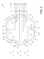
- FIG. 3 is an electrical circuit diagram of transformer 20 implemented according to aspects of the present techniques.
- the transformer 20 includes 3 coils 32, 34 and 36 coupled to each other to form a hexagon 38. Further each coil has a plurality of windings. In the illustrated embodiment, each coil includes five separate windings and is positioned as described below.
- the first coil 32 includes windings 52 and 54 formed on leg 40 of the hexagon 38.
- the first coil further includes windings 56, 58 and 60 formed on the fourth leg 46 of the hexagon 38.
- the second coil 34 includes windings 62, 64 and 66 formed on the second leg 42 of the hexagon 38.
- the second coil 34 further includes windings 68 and 70 on the fifth leg 48 of the hexagon 38.
- the third coil 36 includes windings 72 and 74 on the third leg 44 of the hexagon 38, and further includes windings 76, 78 and 80 on the sixth leg 50 of the hexagon 38.
- Transformer 20 includes 9 output terminals 21-A through 21-1 as shown.
- the first output terminal 21-A is positioned at node 81 between the first winding 52 and second winding 54 of the first coil 32.
- the second output terminal 21-B is positioned at node 82 between first winding 62 and second winding 64 of the second coil 34.
- the third output terminal 21-C is positioned at node 83 between the second winding 64 and third winding 66 of the second coil 34.
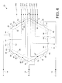
- FIG. 4 illustrates an alternate embodiment of the transformer 20.
- the input terminal 14 is coupled to the first coil 32.
- Input terminal 16 is coupled to second coil 34 and input terminal 18 is coupled to third coil 36. More specifically, the input terminal 14 is coupled to the second winding 54 of first coil 32 and is configured to alter a number of turns of the winding 54 on either side of the input terminal.
- input terminal 16 is coupled to fifth winding 70 of second coil 34 and is configured to alter a number of turns of the winding 70 on either side of the input terminal.
- input terminal 18 is coupled to second winding 74 of third coil 36 and is configured to alter a number of turns of the winding 74on either side of the input terminal.
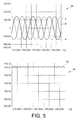
- FIG. 5 is a graph depicting the power at the input and the output of the power system of FIG. 1 .
- Graph 94 depicts the 3 phase input AC power generated by a 3 phase power source.
- the 3 phases of the input AC power are denoted by the letters A, B, and C, respectively.
- the 3 phase input power is provided to a transformer as described with reference to FIG. 3 and FIG. 4 .
- first, second and third coils are linked together to form a transformer.
- Each coil includes a first, second, third, fourth and fifth windings.
- the first, second and third coils are coupled together to form of a polygon as discussed above, such as a hexagon.
- the above described invention has several advantages including operating the transformer as a step-up or step-down transformer without using additional windings. Also, the transformer can be operated for a load at a higher voltage than the input voltage. In addition, the transformer can be used to compensate output voltage drops, thereby decreasing system cable costs and also substantially reducing the need for an active front end converter to regulate the bus to a higher voltage level.
Landscapes
- Engineering & Computer Science (AREA)
- Power Engineering (AREA)
- Ac-Ac Conversion (AREA)
- Coils Of Transformers For General Uses (AREA)
Abstract
Description
- The present invention relates generally to power electronic devices such as those used in power conversion systems. More particularly, the present invention relates to transformers configured to convert 3 phase AC power to 9 phase AC power without the use of extra windings.
- Multi-phase transformers are configured to convert a 3-phase AC input power to a multi-phase (e.g. 9 phase) AC output power. Such transformers are typically designed to provide a desired output AC power. The output AC power generated by the transformer may be rectified or filtered before being supplied to a load.
- However, in some situations, the output voltage provided to the load is lower than the output power generated by the transformer due to losses in the output devices such as rectifiers, output filters and/or long cable lengths. One way to reduce such losses is to lower the cable resistance. However, such cables can increase the overall cost of a system.
- Another technique to maintain the desired output power at a load is to include a step-up transformer to compensate for the output voltage drops. Typically, a buck or boost transformer is externally coupled to the multi-phase transformer. In some systems, an extra winding is added to the transformer. However, these approaches increase the overall cost and the size of the transformer.
- Therefore, there is a need to design a multi-phase transformer that can operate as a step-up or step-down transformer without increasing the size or cost of the overall system.
- Briefly, according to one embodiment of the invention, a transformer for converting 3 phase AC to 9 phase AC power is provided. The transformer includes first, second and third coils, each coil having a plurality of serial windings coupled together to form a polygon. The transformer further includes first, second and third input terminals each linked to a respective winding of the first, second and third coils. The input terminals are configured to receive a first, second and third phases of input AC power and at least one selected input terminal of the first, second and third input terminals is adjustable to alter a number of turns of the respective winding of the corresponding first, second or third coil on either side of the selected input terminal. The transformer further includes first through ninth output terminals linkable to first through ninth output power lines.
- In another embodiment, a transformer for converting 3 phase AC to 9 phase AC power includes first, second and third coils, each coil having a plurality of serial windings coupled together to form a hexagon. Each coil comprises five separate windings including first, second, third, fourth and fifth windings. The transformer further includes first, second and third input terminals each linked to a selected winding of one of the first, second and third coils, respectively and configured to receive a first, second and third phases of input power. At least one of the first, second and third input terminals is adjustable to alter a turns ratio of the selected winding of the corresponding first, second or third coil. The transformer further includes first through ninth output terminals linkable to the first through ninth output power lines.
- In another embodiment, a method for making a transformer for converting 3 phase AC to 9 phase AC power is provided. The method comprises linking first, second and third coils, each coil having a plurality of serial windings coupled together to form a transformer, and each coil comprises five separate windings including first, second, third, fourth and fifth windings. The method further includes adjusting a voltage ratio of the transformer by altering a number of a turns of at least a selected one of the windings of the first, second and third coils and coupling 9 output phase lines to first through ninth output terminals of the transformer.
- These and other features, aspects, and advantages of the present invention will become better understood when the following detailed description is read with reference to the accompanying drawings in which like characters represent like parts throughout the drawings, wherein:
-
FIG. 1 is a block diagram of an exemplary embodiment of a power system implemented according to aspects of the present technique; -
FIG. 2 is a front view of a core and coils of transformer according to the present invention; -
FIG. 3 is a circuit diagram of an exemplary embodiment of a transformer implemented according to aspects of the invention; -
FIG. 4 is a circuit diagram of an alternate embodiment of a transformer implemented according to aspects of the invention; -
FIG. 5 is a graphical representation of input AC power and output power of a power system implemented according to aspects of the invention; and -
FIG. 6 is a flow chart illustrating an exemplary technique for making a transformer according to aspects of the present invention. - Turning now to the drawings, and referring first to
FIG. 1 , apower system 10 is illustrated.Power system 10 comprisespower source 12,transformer 20 andrectifier 22. The output power generated by the power system is provided to a load. Examples of loads include motors, drives, and so forth. Each block is described in further detail below. - It should be noted that references in this specification to "one embodiment", "an embodiment", "an exemplary embodiment", indicate that the embodiment described may include a particular feature, structure, or characteristic, but every embodiment may not necessarily include the particular feature, structure, or characteristic. Moreover, such phrases are not necessarily referring to the same embodiment. Further, when a particular feature, structure, or characteristic is described in connection with an embodiment, it is submitted that it is within the knowledge of one skilled in the art to affect such feature, structure, or characteristic in connection with other embodiments whether or not explicitly described.
-
Power source 12 is configured to generate or provide 3 phase AC power, and in many cases may comprise the utility grid. The 3 phase AC power may be provided to various electrical devices such astransformer 20.Transformer 20 is coupled to thepower source 12 and receives 3 phase AC power. The 3 phase AC power is provided to 3separate input terminals -
Rectifier 30 is configured to convert the 9 phase output AC power to corresponding DC voltage across a DC bus. In one embodiment, the rectifier includes a switch-based bridge including two switches for each AC voltage phase which are each linked to the DC bus. The switches are alternately opened and closed in a timed fashion that causes rectification of the 9 phase AC output power generated by the transformer. The rectified output DC power may be provided to a load. Other types and topologies of rectifiers, and indeed other uses for the 9 phase output may be employed. - As described above, the
transformer 20 is configured to convert 3 phase AC power to 9 phase AC power. The components used to constructtransformer 20 is described in further detail below with reference toFIG. 2 . -
FIG. 2 is a block diagram illustrating one embodiment of a transformer implemented according to aspects of the present techniques. Thetransformer 20 is constructed on a laminatedcore 24. In one embodiment, the laminated core is made of electrical grade steel. The laminatedcore 24 includes 3poles core 24 preferably has no other magnetic flux paths than the 3 traversing poles such that the flux flowing through one pole (e.g., pole 34) return upwards through the other two poles (e.g.,pole 32 and 36). - The
poles third coil - Alternatively, several series windings may be constructed using a single wire or all of the windings may be constructed using a single wire. In one embodiment, all of the windings have a similar construction, the distinction being primarily in the number of turns that are included in each winding. The manner in which the windings are linked to form a transformer is described in further detail below.
-
FIG. 3 is an electrical circuit diagram oftransformer 20 implemented according to aspects of the present techniques. Thetransformer 20 includes 3 coils 32, 34 and 36 coupled to each other to form ahexagon 38. Further each coil has a plurality of windings. In the illustrated embodiment, each coil includes five separate windings and is positioned as described below. - As can be seen in
FIG. 3 , thefirst coil 32 includeswindings leg 40 of thehexagon 38. The first coil further includeswindings fourth leg 46 of thehexagon 38. Similarly, thesecond coil 34 includeswindings second leg 42 of thehexagon 38. Thesecond coil 34 further includeswindings fifth leg 48 of thehexagon 38. Lastly thethird coil 36 includeswindings third leg 44 of thehexagon 38, and further includeswindings sixth leg 50 of thehexagon 38. - The
input terminals input terminal 14 is coupled to winding 78 ofcoil 36. Similarly,input terminal 16 is coupled to winding 64 ofcoil 34, andinput terminal 18 is coupled to winding 58 of tocoil 32. -
Transformer 20 includes 9 output terminals 21-A through 21-1 as shown. The first output terminal 21-A is positioned atnode 81 between the first winding 52 and second winding 54 of thefirst coil 32. The second output terminal 21-B is positioned atnode 82 between first winding 62 and second winding 64 of thesecond coil 34. The third output terminal 21-C is positioned atnode 83 between the second winding 64 and third winding 66 of thesecond coil 34. - The fourth output terminal 21-D is positioned at
node 84 between the first winding 72 and second winding 74 of thethird coil 36. The fifth output terminal 21-E is positioned atnode 85 between the third winding 56 and fourth winding 58 of thefirst coil 32. The sixth output terminal 21-F is positioned atnode 86 between the fourth winding 58 and fifth winding 60 of thefirst coil 32. - The seventh output terminal 21-G is positioned at
node 87 between the fourth winding 68 and fifth winding 70 of thesecond coil 34. The eighth output terminal 21-H is positioned atnode 88 between the third winding 76 and fourth winding 78 of thethird coil 36. The ninth output terminal 21-1 is positioned atnode 89 between the fourth winding 78 and fifth winding 80 of thethird coil 36. - In the embodiment illustrated in
FIG. 3 ,input terminal 18 is adjustable to alter a number of turns of the winding 58 offirst coil 32 on either side of the terminal. By adjusting the number of turns in the windings, a voltage ratio of the transformer is adjusted. Thus, the voltage ratio of the transformer is adjustable without the use of extra windings. -
FIG. 4 illustrates an alternate embodiment of thetransformer 20. In the illustrated embodiment, theinput terminal 14 is coupled to thefirst coil 32.Input terminal 16 is coupled tosecond coil 34 andinput terminal 18 is coupled tothird coil 36. More specifically, theinput terminal 14 is coupled to the second winding 54 offirst coil 32 and is configured to alter a number of turns of the winding 54 on either side of the input terminal. Similarly,input terminal 16 is coupled to fifth winding 70 ofsecond coil 34 and is configured to alter a number of turns of the winding 70 on either side of the input terminal. Further,input terminal 18 is coupled to second winding 74 ofthird coil 36 and is configured to alter a number of turns of the winding 74on either side of the input terminal. - The voltage ratio of the transformer is thus adjusted by adjusting the number of turns in
windings -
FIG. 5 is a graph depicting the power at the input and the output of the power system ofFIG. 1 .Graph 94 depicts the 3 phase input AC power generated by a 3 phase power source. The 3 phases of the input AC power are denoted by the letters A, B, and C, respectively. The 3 phase input power is provided to a transformer as described with reference toFIG. 3 andFIG. 4 . - In one embodiment, input terminal of the transformer is adjusted such that a turns ratio of winding 58 of the
first coil 32 is approximately 0.6736. The corresponding outputDC bus voltage 98 is about 765 V as indicated ingraph 96. Thus, the load can be operated at 480 V even with a 400 V input source voltages. -
FIG. 6 is a flow chart illustrating one method for making a multi-phase transformer described above. The transformer is configured to generate a 9 phase output power from a 3 phase input power. Theflow chart 100 describes one method by which the multi-phase transformer is constructed. Each step of the flow chart is described in detail below. - At
step 102, first, second and third coils are linked together to form a transformer. Each coil includes a first, second, third, fourth and fifth windings. In one embodiment, the first, second and third coils are coupled together to form of a polygon as discussed above, such as a hexagon. - At
step 104, a voltage ratio of the transformer is adjusted by adjusting at least one winding in the first, second or third coil. In one embodiment, the turns ratio of the second winding of the first coil is adjusted. In another embodiment, the turns ratio of the fourth winding of the first coil is adjusted. - At
step 106, 9 output phase lines are coupled to first through ninth output terminals of the transformer. The output terminals are positioned at the intersection of the windings as shown inFIG. 3 andFIG. 4 . The 9 output phase lines may be coupled to other electronic components such as rectifiers, filters and the like. - The above described invention has several advantages including operating the transformer as a step-up or step-down transformer without using additional windings. Also, the transformer can be operated for a load at a higher voltage than the input voltage. In addition, the transformer can be used to compensate output voltage drops, thereby decreasing system cable costs and also substantially reducing the need for an active front end converter to regulate the bus to a higher voltage level.
- While only certain features of the invention have been illustrated and described herein, many modifications and changes will occur to those skilled in the art. It is, therefore, to be understood that the appended claims are intended to cover all such modifications and changes as fall within the true spirit of the invention.
-
- Embodiment 1: A transformer for converting 3 phase AC to 9 phase AC power, the transformer comprising:
- first, second and third coils, each coil having a plurality of serial windings coupled together to form a polygon;
- first, second and third input terminals each linked to a respective winding of the first, second and third coils, and configured to receive a first, second and third phases of input AC power, wherein at least one selected input terminal of the first, second and third input terminals is adjustable to alter a number of turns of the respective winding of the corresponding first, second or third coil on either side of the selected input terminal; and
- first through ninth output terminals linkable to first through ninth output power lines.
- Embodiment 2: The transformer of embodiment 1, wherein each coil forms five separate windings including first, second, third, fourth and fifth windings.
- Embodiment 3: The transformer of embodiment 2, wherein the polygon is a hexagon.
- Embodiment 4: The transformer of embodiment 3, wherein the first and second windings of the first coil are coupled in series to form a first leg of the hexagon and the third through fifth windings of the first coil are coupled in series to form a fourth leg of the hexagon; and wherein the first, second and third windings of the second coil are coupled in series to form a second leg of the hexagon and the fourth and fifth windings of the second coil are coupled in series to form a fifth leg of the hexagon; and wherein the first and second windings of the third coil are coupled in series to form a third leg of the hexagon, and the third through fifth windings of the third coil are coupled in series to form a sixth leg of the hexagon.
- Embodiment 5: The transformer of embodiment 4, wherein:
- the first output terminal is positioned between the first and second windings of the first coil;
- the second output terminal is positioned between first and second windings of the second coil;
- the third output terminal is positioned between the second and third windings of the second coil;
- the fourth output terminal is positioned between the first and second windings of the third coil,
- the fifth output terminal is positioned between the third and fourth windings of the first coil,
- the sixth output terminal is positioned between the fourth and fifth windings of the first coil,
- the seventh output terminal is positioned between the fourth and fifth windings of the second coil,
- the eighth output terminal is positioned between the third and fourth windings of the third coil; and
- the ninth output terminal is positioned between the fourth and fifth windings of the third coil.
- Embodiment 6: The transformer of embodiment 4, wherein the first input terminal is adjustable to alter the number of windings on the second winding of the first coil.
- Embodiment 7: The transformer of embodiment 4, wherein the third input terminal is adjustably positioned to alter the number of windings on the fourth winding of the first coil.
- Embodiment 8: The transformer of embodiment 1, wherein at least one of the first, second and third input terminals is configured to adjust a voltage transfer ratio of the transformer.
- Embodiment 9: The transformer of embodiment 8, wherein the voltage ratio is adjustable to operate the transformer as a step-up transformer or a step-down transformer.
- Embodiment 10: A transformer for converting 3 phase AC to 9 phase AC power, the transformer comprising:
- first, second and third coils, each coil having a plurality of serial windings coupled together to form a hexagon, wherein each coil comprises five separate windings including first, second, third, fourth and fifth windings;
- first, second and third input terminals each linked to a selected winding of one of the first, second and third coils, respectively, and configured to receive a first, second and third phases of input power, wherein at least one of the first, second and third input terminals is adjustable to alter a turns ratio of the selected winding of the corresponding first, second or third coil; and
- first through ninth output terminals linkable to the first through ninth output power lines.
- Embodiment 11: The transformer of
embodiment 10, wherein the first and second windings of the first coil are coupled in series to form a first leg of the hexagon and the third through fifth windings of the first coil are coupled in series to form a fourth leg of the hexagon; and wherein the first, second and third windings of the second coil are coupled in series to form a second leg of the hexagon and the fourth and fifth windings of the second coil are coupled in series to form a fifth leg of the hexagon; and wherein the first and second windings of the third coil are coupled in series to form a third leg of the hexagon, and the third through fifth windings of the third coil are coupled in series to form a sixth leg of the hexagon. - Embodiment 12: The transformer of embodiment 11, wherein:
- the first output terminal is positioned between the first and second windings of the first coil;
- the second output terminal is positioned between first and second windings of the second coil;
- the third output terminal is positioned between the second and third windings of the second coil;
- the fourth output terminal is positioned between the first and second windings of the third coil,
- the fifth output terminal is positioned between the third and fourth windings of the first coil,
- the sixth output terminal is positioned between the fourth and fifth windings of the first coil,
- the seventh output terminal is positioned between the fourth and fifth windings of the second coil,
- the eighth output terminal is positioned between the third and fourth windings of the third coil; and
- the ninth output terminal is positioned between the fourth and fifth windings of the third coil.
- Embodiment 13: The transformer of
embodiment 10, wherein at least one of the first, second and third input terminals is configured to adjust a voltage transfer ratio of the transformer. - Embodiment 14: The transformer of embodiment 13, wherein the voltage ratio is adjustable to operate the transformer as a step-up transformer or a step-down transformer.
- Embodiment 15; A method for making a transformer for converting 3 phase AC to 9 phase AC power, the method comprising:
- linking first, second and third coils, each coil having a plurality of serial windings coupled together to form a transformer, wherein each coil comprises five separate windings including first, second, third, fourth and fifth windings;
- adjusting a voltage ratio of the transformer by altering a number of a turns ratio of at least a selected one of the windings of the first, second and third coils; and
- coupling 9 output phase lines to first through ninth output terminals of the transformer.
- Embodiment 16: The method of embodiment 15, wherein the first, second and third coil are linked together in a hexagon shape.
- Embodiment 17: The method of
embodiment 16, comprising:- coupling the first and second windings of the first coil in series to form a first leg of the hexagon, and coupling the third through fifth windings of the first coil in series to form a fourth leg of the hexagon;
- coupling the first, second and third windings of the second coil in series to form a second leg of the hexagon and the forth and fifth windings are coupled in series forming a fifth leg of the hexagon; and
- coupling the first and second windings of the third coil in series to form a third leg of the hexagon, and coupling the third through fifth windings in series to form a sixth leg of the hexagon.
- Embodiment 18: The method of embodiment 15, wherein the turns ratio is adjusted by adjusting a position of a first input terminal to alter the number of turns on either side of the first input terminal of the second winding of the first coil.
- Embodiment 19: The method of embodiment 15, wherein the turns ratio is adjusted by adjusting a position of a third input terminal to alter the number of turns on either side of the third input terminal of the fourth winding of the first coil.
- Embodiment 20: The method of
embodiment 16, wherein the voltage ratio is adjusted to operate the transformer as a step-up transformer or a step-down transformer.
Claims (15)
- A transformer for converting 3 phase AC to 9 phase AC power, the transformer comprising:first, second and third coils, each coil having a plurality of serial windings coupled together to form a polygon;first, second and third input terminals each linked to a respective winding of the first, second and third coils, and configured to receive a first, second and third phases of input AC power, wherein at least one selected input terminal of the first, second and third input terminals is adjustable to alter a number of turns of the respective winding of the corresponding first, second or third coil on either side of the selected input terminal; andfirst through ninth output terminals linkable to first through ninth output power lines.
- The transformer of claim 1, wherein each coil forms five separate windings including first, second, third, fourth and fifth windings.
- The transformer of claim 2, wherein the polygon is a hexagon.
- The transformer of claim 3, wherein the first and second windings of the first coil are coupled in series to form a first leg of the hexagon and the third through fifth windings of the first coil are coupled in series to form a fourth leg of the hexagon; and wherein the first, second and third windings of the second coil are coupled in series to form a second leg of the hexagon and the fourth and fifth windings of the second coil are coupled in series to form a fifth leg of the hexagon; and wherein the first and second windings of the third coil are coupled in series to form a third leg of the hexagon, and the third through fifth windings of the third coil are coupled in series to form a sixth leg of the hexagon.
- The transformer of claim 4, wherein:the first output terminal is positioned between the first and second windings of the first coil;the second output terminal is positioned between first and second windings of the second coil;the third output terminal is positioned between the second and third windings of the second coil;the fourth output terminal is positioned between the first and second windings of the third coil,the fifth output terminal is positioned between the third and fourth windings of the first coil,the sixth output terminal is positioned between the fourth and fifth windings of the first coil,the seventh output terminal is positioned between the fourth and fifth windings of the second coil,the eighth output terminal is positioned between the third and fourth windings of the third coil; andthe ninth output terminal is positioned between the fourth and fifth windings of the third coil.
- The transformer of claim 4, wherein the first input terminal is adjustable to alter the number of windings on the second winding of the first coil, or
wherein the third input terminal is adjustably positioned to alter the number of windings on the fourth winding of the first coil. - The transformer of any one of claims 1 to 6, wherein at least one of the first, second and third input terminals is configured to adjust a voltage transfer ratio of the transformer, and/or
wherein the voltage ratio is adjustable to operate the transformer as a step-up transformer or a step-down transformer. - A transformer for converting 3 phase AC to 9 phase AC power, the transformer comprising:first, second and third coils, each coil having a plurality of serial windings coupled together to form a hexagon, wherein each coil comprises five separate windings including first, second, third, fourth and fifth windings;first, second and third input terminals each linked to a selected winding of one of the first, second and third coils, respectively, and configured to receive a first, second and third phases of input power, wherein at least one of the first, second and third input terminals is adjustable to alter a turns ratio of the selected winding of the corresponding first, second or third coil; andfirst through ninth output terminals linkable to the first through ninth output power lines.
- The transformer of claim 8, wherein the first and second windings of the first coil are coupled in series to form a first leg of the hexagon and the third through fifth windings of the first coil are coupled in series to form a fourth leg of the hexagon; and wherein the first, second and third windings of the second coil are coupled in series to form a second leg of the hexagon and the fourth and fifth windings of the second coil are coupled in series to form a fifth leg of the hexagon; and wherein the first and second windings of the third coil are coupled in series to form a third leg of the hexagon, and the third through fifth windings of the third coil are coupled in series to form a sixth leg of the hexagon.
- The transformer of claim 9, wherein:the first output terminal is positioned between the first and second windings of the first coil;the second output terminal is positioned between first and second windings of the second coil;the third output terminal is positioned between the second and third windings of the second coil;the fourth output terminal is positioned between the first and second windings of the third coil,the fifth output terminal is positioned between the third and fourth windings of the first coil,the sixth output terminal is positioned between the fourth and fifth windings of the first coil,the seventh output terminal is positioned between the fourth and fifth windings of the second coil,the eighth output terminal is positioned between the third and fourth windings of the third coil; andthe ninth output terminal is positioned between the fourth and fifth windings of the third coil.
- The transformer of any one of claims 8 to 10, wherein at least one of the first, second and third input terminals is configured to adjust a voltage transfer ratio of the transformer, and/or
wherein the voltage ratio is adjustable to operate the transformer as a step-up transformer or a step-down transformer. - A method for making a transformer for converting 3 phase AC to 9 phase AC power, the method comprising:linking first, second and third coils, each coil having a plurality of serial windings coupled together to form a transformer, wherein each coil comprises five separate windings including first, second, third, fourth and fifth windings;adjusting a voltage ratio of the transformer by altering a number of a turns ratio of at least a selected one of the windings of the first, second and third coils; andcoupling 9 output phase lines to first through ninth output terminals of the transformer.
- The method of claim 12, wherein the first, second and third coil are linked together in a hexagon shape.
- The method of claim 13, comprising:coupling the first and second windings of the first coil in series to form a first leg of the hexagon, and coupling the third through fifth windings of the first coil in series to form a fourth leg of the hexagon;coupling the first, second and third windings of the second coil in series to form a second leg of the hexagon and the forth and fifth windings are coupled in series forming a fifth leg of the hexagon; andcoupling the first and second windings of the third coil in series to form a third leg of the hexagon, and coupling the third through fifth windings in series to form a sixth leg of the hexagon.
- The method of any one of claims 12 to 14, wherein the turns ratio is adjusted by adjusting a position of a first input terminal to alter the number of turns on either side of the first input terminal of the second winding of the first coil, or
wherein the turns ratio is adjusted by adjusting a position of a third input terminal to alter the number of turns on either side of the third input terminal of the fourth winding of the first coil, and/or
wherein the voltage ratio is adjusted to operate the transformer as a step-up transformer or a step-down transformer.
Applications Claiming Priority (1)
| Application Number | Priority Date | Filing Date | Title |
|---|---|---|---|
| US12/901,251 US8395469B2 (en) | 2010-10-08 | 2010-10-08 | Multi-phase transformer |
Publications (2)
| Publication Number | Publication Date |
|---|---|
| EP2439757A1 true EP2439757A1 (en) | 2012-04-11 |
| EP2439757B1 EP2439757B1 (en) | 2013-12-11 |
Family
ID=44759570
Family Applications (1)
| Application Number | Title | Priority Date | Filing Date |
|---|---|---|---|
| EP11184528.5A Not-in-force EP2439757B1 (en) | 2010-10-08 | 2011-10-10 | Multi-phase transformer |
Country Status (3)
| Country | Link |
|---|---|
| US (1) | US8395469B2 (en) |
| EP (1) | EP2439757B1 (en) |
| CN (1) | CN202652075U (en) |
Families Citing this family (4)
| Publication number | Priority date | Publication date | Assignee | Title |
|---|---|---|---|---|
| US20140266557A1 (en) * | 2013-03-15 | 2014-09-18 | Jacob Justice | Inherently Balanced Phase Shifting AutoTransformer |
| US9705442B2 (en) * | 2013-07-18 | 2017-07-11 | Rensselaer Polytechnic Institute | Asymmetrical multi-lane multi-phase motor drives |
| RU2665686C2 (en) * | 2017-04-21 | 2018-09-04 | Евгений Николаевич Коптяев | Multipole ring winding |
| RU2665687C2 (en) * | 2017-04-28 | 2018-09-04 | Евгений Николаевич Коптяев | Improved multipole ring winding |
Citations (2)
| Publication number | Priority date | Publication date | Assignee | Title |
|---|---|---|---|---|
| US6249443B1 (en) * | 2000-07-14 | 2001-06-19 | Rockwell Technologies, Llc | Nine-phase transformer |
| US6335872B1 (en) * | 2000-07-14 | 2002-01-01 | Rockwell Automation Technologies, Inc. | Nine-phase transformer |
Family Cites Families (14)
| Publication number | Priority date | Publication date | Assignee | Title |
|---|---|---|---|---|
| US2517396A (en) * | 1948-10-01 | 1950-08-01 | Vickers Inc | Means for increasing frequency |
| GB986384A (en) * | 1961-04-14 | 1965-03-17 | Nat Res Dev | Improvements in or relating to rotary electric machines |
| US3392320A (en) * | 1965-01-28 | 1968-07-09 | Inductotherm Corp | Static frequency multiplier |
| US4320328A (en) * | 1979-03-09 | 1982-03-16 | Vibranetics, Inc. | Apparatus for full voltage start of vibratory excitors |
| US4439823A (en) * | 1982-01-11 | 1984-03-27 | Westinghouse Electric Corp. | Converting multiphase power from one frequency to another using current waveforms |
| CH659742A5 (en) * | 1983-04-08 | 1987-02-13 | Bbc Brown Boveri & Cie | CIRCUIT ARRANGEMENT FOR INCREASING STABILITY IN A THREE-PHASE NETWORK SUPPLIED BY A GENERATOR. |
| US5455759A (en) * | 1994-06-24 | 1995-10-03 | Paice; Derek A. | Symmetrical, phase-shifting, fork transformer |
| US6191968B1 (en) * | 2000-03-23 | 2001-02-20 | Derek A Paice | Wye connected 3-phase to 9-phase auto-transformer with reduced winding currents |
| US6343021B1 (en) * | 2000-05-09 | 2002-01-29 | Floyd L. Williamson | Universal input/output power supply with inherent near unity power factor |
| US6498736B1 (en) * | 2001-03-27 | 2002-12-24 | Baldor Electric Company | Harmonic filter with low cost magnetics |
| US6385064B1 (en) * | 2001-05-07 | 2002-05-07 | Rockwell Technologies, Llc | Harmonic blocking reactor for nine-phase converter system |
| US7233506B1 (en) * | 2006-04-03 | 2007-06-19 | Derek Albert Paice | Low kVA/kW transformers for AC to DC multipulse converters |
| US7274280B1 (en) | 2006-05-18 | 2007-09-25 | Derek Albert Paice | Nine-phase step-up/step-down autotransformer |
| US7863766B2 (en) * | 2009-06-30 | 2011-01-04 | Teco-Westinghouse Motor Company | Power converter for use with wind generator |
-
2010
- 2010-10-08 US US12/901,251 patent/US8395469B2/en active Active
-
2011
- 2011-10-10 CN CN201120403081.1U patent/CN202652075U/en not_active Expired - Lifetime
- 2011-10-10 EP EP11184528.5A patent/EP2439757B1/en not_active Not-in-force
Patent Citations (2)
| Publication number | Priority date | Publication date | Assignee | Title |
|---|---|---|---|---|
| US6249443B1 (en) * | 2000-07-14 | 2001-06-19 | Rockwell Technologies, Llc | Nine-phase transformer |
| US6335872B1 (en) * | 2000-07-14 | 2002-01-01 | Rockwell Automation Technologies, Inc. | Nine-phase transformer |
Also Published As
| Publication number | Publication date |
|---|---|
| EP2439757B1 (en) | 2013-12-11 |
| US20120086532A1 (en) | 2012-04-12 |
| US8395469B2 (en) | 2013-03-12 |
| CN202652075U (en) | 2013-01-02 |
Similar Documents
| Publication | Publication Date | Title |
|---|---|---|
| CN103582997B (en) | AC/DC power conversion system and manufacturing method thereof | |
| US11909311B2 (en) | Power converter, inductor element and control method of phase shedding | |
| TWI439031B (en) | Asymmetrical coupled inductors, multiphase dc-to-dc converters, and controller for controlling operation of multiphase dc-to-dc converter | |
| KR101030466B1 (en) | Bidirectional DC / DC Converters | |
| US8737097B1 (en) | Electronically isolated method for an auto transformer 12-pulse rectification scheme suitable for use with variable frequency drives | |
| US9721719B1 (en) | Coupled inductors with leakage plates, and associated systems and methods | |
| US20080019158A1 (en) | Multi-phase buck converter with a plurality of coupled inductors | |
| EP2320551B1 (en) | Thirty-six pulse power transformer and power converter incorporating same | |
| JP5971607B1 (en) | Power circuit | |
| US10536079B2 (en) | DC-to-DC converters capable of discontinuous conduction mode, and associated methods | |
| US7274280B1 (en) | Nine-phase step-up/step-down autotransformer | |
| CN114424304A (en) | Winding arrangement as part of an integrated structure for an intermediate frequency transformer | |
| EP2439756A2 (en) | Multi-phase transformer | |
| US8395469B2 (en) | Multi-phase transformer | |
| CN113241952A (en) | Isolated bidirectional converter and control method thereof | |
| US10270344B2 (en) | Multiphase voltage converter with coupled inductors of reduced winding loss and core loss | |
| CN112820524B (en) | Multiphase transformer and rectifier system | |
| US10998819B2 (en) | Method and system for DC voltage converting | |
| CN112820523B (en) | Multiphase autotransformer and rectifier system | |
| JP6045664B1 (en) | Power converter | |
| JP5887700B2 (en) | High frequency transformer | |
| EP3926648A1 (en) | Core structure for magnetic components and converter therewith | |
| RU91486U1 (en) | MULTI-PHASE CONVERTER | |
| US20250226149A1 (en) | Magnetic component, electric circuit and power conversion circuit | |
| RU2503121C1 (en) | Five-phase phase changer |
Legal Events
| Date | Code | Title | Description |
|---|---|---|---|
| AK | Designated contracting states |
Kind code of ref document: A1 Designated state(s): AL AT BE BG CH CY CZ DE DK EE ES FI FR GB GR HR HU IE IS IT LI LT LU LV MC MK MT NL NO PL PT RO RS SE SI SK SM TR |
|
| AX | Request for extension of the european patent |
Extension state: BA ME |
|
| PUAI | Public reference made under article 153(3) epc to a published international application that has entered the european phase |
Free format text: ORIGINAL CODE: 0009012 |
|
| 17P | Request for examination filed |
Effective date: 20121011 |
|
| RIC1 | Information provided on ipc code assigned before grant |
Ipc: H01F 30/14 20060101AFI20121128BHEP |
|
| GRAP | Despatch of communication of intention to grant a patent |
Free format text: ORIGINAL CODE: EPIDOSNIGR1 |
|
| GRAP | Despatch of communication of intention to grant a patent |
Free format text: ORIGINAL CODE: EPIDOSNIGR1 |
|
| INTG | Intention to grant announced |
Effective date: 20130603 |
|
| GRAS | Grant fee paid |
Free format text: ORIGINAL CODE: EPIDOSNIGR3 |
|
| GRAA | (expected) grant |
Free format text: ORIGINAL CODE: 0009210 |
|
| AK | Designated contracting states |
Kind code of ref document: B1 Designated state(s): AL AT BE BG CH CY CZ DE DK EE ES FI FR GB GR HR HU IE IS IT LI LT LU LV MC MK MT NL NO PL PT RO RS SE SI SK SM TR |
|
| REG | Reference to a national code |
Ref country code: GB Ref legal event code: FG4D |
|
| REG | Reference to a national code |
Ref country code: CH Ref legal event code: EP |
|
| REG | Reference to a national code |
Ref country code: AT Ref legal event code: REF Ref document number: 644952 Country of ref document: AT Kind code of ref document: T Effective date: 20140115 |
|
| REG | Reference to a national code |
Ref country code: IE Ref legal event code: FG4D |
|
| REG | Reference to a national code |
Ref country code: DE Ref legal event code: R096 Ref document number: 602011004125 Country of ref document: DE Effective date: 20140206 |
|
| REG | Reference to a national code |
Ref country code: NL Ref legal event code: VDEP Effective date: 20131211 |
|
| REG | Reference to a national code |
Ref country code: AT Ref legal event code: MK05 Ref document number: 644952 Country of ref document: AT Kind code of ref document: T Effective date: 20131211 |
|
| PG25 | Lapsed in a contracting state [announced via postgrant information from national office to epo] |
Ref country code: FI Free format text: LAPSE BECAUSE OF FAILURE TO SUBMIT A TRANSLATION OF THE DESCRIPTION OR TO PAY THE FEE WITHIN THE PRESCRIBED TIME-LIMIT Effective date: 20131211 Ref country code: NL Free format text: LAPSE BECAUSE OF FAILURE TO SUBMIT A TRANSLATION OF THE DESCRIPTION OR TO PAY THE FEE WITHIN THE PRESCRIBED TIME-LIMIT Effective date: 20131211 Ref country code: NO Free format text: LAPSE BECAUSE OF FAILURE TO SUBMIT A TRANSLATION OF THE DESCRIPTION OR TO PAY THE FEE WITHIN THE PRESCRIBED TIME-LIMIT Effective date: 20140311 Ref country code: LT Free format text: LAPSE BECAUSE OF FAILURE TO SUBMIT A TRANSLATION OF THE DESCRIPTION OR TO PAY THE FEE WITHIN THE PRESCRIBED TIME-LIMIT Effective date: 20131211 Ref country code: SE Free format text: LAPSE BECAUSE OF FAILURE TO SUBMIT A TRANSLATION OF THE DESCRIPTION OR TO PAY THE FEE WITHIN THE PRESCRIBED TIME-LIMIT Effective date: 20131211 Ref country code: HR Free format text: LAPSE BECAUSE OF FAILURE TO SUBMIT A TRANSLATION OF THE DESCRIPTION OR TO PAY THE FEE WITHIN THE PRESCRIBED TIME-LIMIT Effective date: 20131211 |
|
| REG | Reference to a national code |
Ref country code: LT Ref legal event code: MG4D |
|
| PG25 | Lapsed in a contracting state [announced via postgrant information from national office to epo] |
Ref country code: AT Free format text: LAPSE BECAUSE OF FAILURE TO SUBMIT A TRANSLATION OF THE DESCRIPTION OR TO PAY THE FEE WITHIN THE PRESCRIBED TIME-LIMIT Effective date: 20131211 Ref country code: CY Free format text: LAPSE BECAUSE OF FAILURE TO SUBMIT A TRANSLATION OF THE DESCRIPTION OR TO PAY THE FEE WITHIN THE PRESCRIBED TIME-LIMIT Effective date: 20131211 Ref country code: LV Free format text: LAPSE BECAUSE OF FAILURE TO SUBMIT A TRANSLATION OF THE DESCRIPTION OR TO PAY THE FEE WITHIN THE PRESCRIBED TIME-LIMIT Effective date: 20131211 Ref country code: RS Free format text: LAPSE BECAUSE OF FAILURE TO SUBMIT A TRANSLATION OF THE DESCRIPTION OR TO PAY THE FEE WITHIN THE PRESCRIBED TIME-LIMIT Effective date: 20131211 |
|
| PG25 | Lapsed in a contracting state [announced via postgrant information from national office to epo] |
Ref country code: BE Free format text: LAPSE BECAUSE OF FAILURE TO SUBMIT A TRANSLATION OF THE DESCRIPTION OR TO PAY THE FEE WITHIN THE PRESCRIBED TIME-LIMIT Effective date: 20131211 Ref country code: EE Free format text: LAPSE BECAUSE OF FAILURE TO SUBMIT A TRANSLATION OF THE DESCRIPTION OR TO PAY THE FEE WITHIN THE PRESCRIBED TIME-LIMIT Effective date: 20131211 Ref country code: IS Free format text: LAPSE BECAUSE OF FAILURE TO SUBMIT A TRANSLATION OF THE DESCRIPTION OR TO PAY THE FEE WITHIN THE PRESCRIBED TIME-LIMIT Effective date: 20140411 |
|
| PG25 | Lapsed in a contracting state [announced via postgrant information from national office to epo] |
Ref country code: RO Free format text: LAPSE BECAUSE OF FAILURE TO SUBMIT A TRANSLATION OF THE DESCRIPTION OR TO PAY THE FEE WITHIN THE PRESCRIBED TIME-LIMIT Effective date: 20131211 Ref country code: PL Free format text: LAPSE BECAUSE OF FAILURE TO SUBMIT A TRANSLATION OF THE DESCRIPTION OR TO PAY THE FEE WITHIN THE PRESCRIBED TIME-LIMIT Effective date: 20131211 Ref country code: PT Free format text: LAPSE BECAUSE OF FAILURE TO SUBMIT A TRANSLATION OF THE DESCRIPTION OR TO PAY THE FEE WITHIN THE PRESCRIBED TIME-LIMIT Effective date: 20140411 Ref country code: SK Free format text: LAPSE BECAUSE OF FAILURE TO SUBMIT A TRANSLATION OF THE DESCRIPTION OR TO PAY THE FEE WITHIN THE PRESCRIBED TIME-LIMIT Effective date: 20131211 Ref country code: ES Free format text: LAPSE BECAUSE OF FAILURE TO SUBMIT A TRANSLATION OF THE DESCRIPTION OR TO PAY THE FEE WITHIN THE PRESCRIBED TIME-LIMIT Effective date: 20131211 Ref country code: CZ Free format text: LAPSE BECAUSE OF FAILURE TO SUBMIT A TRANSLATION OF THE DESCRIPTION OR TO PAY THE FEE WITHIN THE PRESCRIBED TIME-LIMIT Effective date: 20131211 |
|
| REG | Reference to a national code |
Ref country code: DE Ref legal event code: R097 Ref document number: 602011004125 Country of ref document: DE |
|
| PLBE | No opposition filed within time limit |
Free format text: ORIGINAL CODE: 0009261 |
|
| STAA | Information on the status of an ep patent application or granted ep patent |
Free format text: STATUS: NO OPPOSITION FILED WITHIN TIME LIMIT |
|
| PG25 | Lapsed in a contracting state [announced via postgrant information from national office to epo] |
Ref country code: DK Free format text: LAPSE BECAUSE OF FAILURE TO SUBMIT A TRANSLATION OF THE DESCRIPTION OR TO PAY THE FEE WITHIN THE PRESCRIBED TIME-LIMIT Effective date: 20131211 |
|
| 26N | No opposition filed |
Effective date: 20140912 |
|
| REG | Reference to a national code |
Ref country code: DE Ref legal event code: R097 Ref document number: 602011004125 Country of ref document: DE Effective date: 20140912 |
|
| PG25 | Lapsed in a contracting state [announced via postgrant information from national office to epo] |
Ref country code: SI Free format text: LAPSE BECAUSE OF FAILURE TO SUBMIT A TRANSLATION OF THE DESCRIPTION OR TO PAY THE FEE WITHIN THE PRESCRIBED TIME-LIMIT Effective date: 20131211 |
|
| PG25 | Lapsed in a contracting state [announced via postgrant information from national office to epo] |
Ref country code: LU Free format text: LAPSE BECAUSE OF FAILURE TO SUBMIT A TRANSLATION OF THE DESCRIPTION OR TO PAY THE FEE WITHIN THE PRESCRIBED TIME-LIMIT Effective date: 20141010 Ref country code: MC Free format text: LAPSE BECAUSE OF FAILURE TO SUBMIT A TRANSLATION OF THE DESCRIPTION OR TO PAY THE FEE WITHIN THE PRESCRIBED TIME-LIMIT Effective date: 20131211 |
|
| REG | Reference to a national code |
Ref country code: CH Ref legal event code: PL |
|
| REG | Reference to a national code |
Ref country code: IE Ref legal event code: MM4A |
|
| PG25 | Lapsed in a contracting state [announced via postgrant information from national office to epo] |
Ref country code: CH Free format text: LAPSE BECAUSE OF NON-PAYMENT OF DUE FEES Effective date: 20141031 Ref country code: LI Free format text: LAPSE BECAUSE OF NON-PAYMENT OF DUE FEES Effective date: 20141031 |
|
| REG | Reference to a national code |
Ref country code: FR Ref legal event code: PLFP Year of fee payment: 5 |
|
| PG25 | Lapsed in a contracting state [announced via postgrant information from national office to epo] |
Ref country code: IE Free format text: LAPSE BECAUSE OF NON-PAYMENT OF DUE FEES Effective date: 20141010 |
|
| PG25 | Lapsed in a contracting state [announced via postgrant information from national office to epo] |
Ref country code: SM Free format text: LAPSE BECAUSE OF FAILURE TO SUBMIT A TRANSLATION OF THE DESCRIPTION OR TO PAY THE FEE WITHIN THE PRESCRIBED TIME-LIMIT Effective date: 20131211 |
|
| PG25 | Lapsed in a contracting state [announced via postgrant information from national office to epo] |
Ref country code: IT Free format text: LAPSE BECAUSE OF FAILURE TO SUBMIT A TRANSLATION OF THE DESCRIPTION OR TO PAY THE FEE WITHIN THE PRESCRIBED TIME-LIMIT Effective date: 20131211 Ref country code: BG Free format text: LAPSE BECAUSE OF FAILURE TO SUBMIT A TRANSLATION OF THE DESCRIPTION OR TO PAY THE FEE WITHIN THE PRESCRIBED TIME-LIMIT Effective date: 20131211 Ref country code: GR Free format text: LAPSE BECAUSE OF FAILURE TO SUBMIT A TRANSLATION OF THE DESCRIPTION OR TO PAY THE FEE WITHIN THE PRESCRIBED TIME-LIMIT Effective date: 20140312 |
|
| PG25 | Lapsed in a contracting state [announced via postgrant information from national office to epo] |
Ref country code: MT Free format text: LAPSE BECAUSE OF FAILURE TO SUBMIT A TRANSLATION OF THE DESCRIPTION OR TO PAY THE FEE WITHIN THE PRESCRIBED TIME-LIMIT Effective date: 20131211 Ref country code: HU Free format text: LAPSE BECAUSE OF FAILURE TO SUBMIT A TRANSLATION OF THE DESCRIPTION OR TO PAY THE FEE WITHIN THE PRESCRIBED TIME-LIMIT; INVALID AB INITIO Effective date: 20111010 Ref country code: TR Free format text: LAPSE BECAUSE OF FAILURE TO SUBMIT A TRANSLATION OF THE DESCRIPTION OR TO PAY THE FEE WITHIN THE PRESCRIBED TIME-LIMIT Effective date: 20131211 |
|
| REG | Reference to a national code |
Ref country code: FR Ref legal event code: PLFP Year of fee payment: 6 |
|
| REG | Reference to a national code |
Ref country code: FR Ref legal event code: PLFP Year of fee payment: 7 |
|
| PG25 | Lapsed in a contracting state [announced via postgrant information from national office to epo] |
Ref country code: MK Free format text: LAPSE BECAUSE OF FAILURE TO SUBMIT A TRANSLATION OF THE DESCRIPTION OR TO PAY THE FEE WITHIN THE PRESCRIBED TIME-LIMIT Effective date: 20131211 |
|
| REG | Reference to a national code |
Ref country code: FR Ref legal event code: PLFP Year of fee payment: 8 |
|
| PG25 | Lapsed in a contracting state [announced via postgrant information from national office to epo] |
Ref country code: AL Free format text: LAPSE BECAUSE OF FAILURE TO SUBMIT A TRANSLATION OF THE DESCRIPTION OR TO PAY THE FEE WITHIN THE PRESCRIBED TIME-LIMIT Effective date: 20131211 |
|
| P01 | Opt-out of the competence of the unified patent court (upc) registered |
Effective date: 20230404 |
|
| PGFP | Annual fee paid to national office [announced via postgrant information from national office to epo] |
Ref country code: GB Payment date: 20230920 Year of fee payment: 13 |
|
| PGFP | Annual fee paid to national office [announced via postgrant information from national office to epo] |
Ref country code: FR Payment date: 20230920 Year of fee payment: 13 |
|
| PGFP | Annual fee paid to national office [announced via postgrant information from national office to epo] |
Ref country code: DE Payment date: 20230920 Year of fee payment: 13 |
|
| REG | Reference to a national code |
Ref country code: DE Ref legal event code: R119 Ref document number: 602011004125 Country of ref document: DE |
|
| GBPC | Gb: european patent ceased through non-payment of renewal fee |
Effective date: 20241010 |
|
| PG25 | Lapsed in a contracting state [announced via postgrant information from national office to epo] |
Ref country code: DE Free format text: LAPSE BECAUSE OF NON-PAYMENT OF DUE FEES Effective date: 20250501 |
|
| PG25 | Lapsed in a contracting state [announced via postgrant information from national office to epo] |
Ref country code: GB Free format text: LAPSE BECAUSE OF NON-PAYMENT OF DUE FEES Effective date: 20241010 |
|
| PG25 | Lapsed in a contracting state [announced via postgrant information from national office to epo] |
Ref country code: FR Free format text: LAPSE BECAUSE OF NON-PAYMENT OF DUE FEES Effective date: 20241031 |