EP2439714A1 - Vehicle surrounding monitor device and method for monitoring surroundings used for vehicle - Google Patents
Vehicle surrounding monitor device and method for monitoring surroundings used for vehicle Download PDFInfo
- Publication number
- EP2439714A1 EP2439714A1 EP09845524A EP09845524A EP2439714A1 EP 2439714 A1 EP2439714 A1 EP 2439714A1 EP 09845524 A EP09845524 A EP 09845524A EP 09845524 A EP09845524 A EP 09845524A EP 2439714 A1 EP2439714 A1 EP 2439714A1
- Authority
- EP
- European Patent Office
- Prior art keywords
- host vehicle
- driver
- monitoring
- traveling
- vehicle
- Prior art date
- Legal status (The legal status is an assumption and is not a legal conclusion. Google has not performed a legal analysis and makes no representation as to the accuracy of the status listed.)
- Granted
Links
Images


Classifications
-
- B—PERFORMING OPERATIONS; TRANSPORTING
- B60—VEHICLES IN GENERAL
- B60W—CONJOINT CONTROL OF VEHICLE SUB-UNITS OF DIFFERENT TYPE OR DIFFERENT FUNCTION; CONTROL SYSTEMS SPECIALLY ADAPTED FOR HYBRID VEHICLES; ROAD VEHICLE DRIVE CONTROL SYSTEMS FOR PURPOSES NOT RELATED TO THE CONTROL OF A PARTICULAR SUB-UNIT
- B60W50/00—Details of control systems for road vehicle drive control not related to the control of a particular sub-unit, e.g. process diagnostic or vehicle driver interfaces
- B60W50/06—Improving the dynamic response of the control system, e.g. improving the speed of regulation or avoiding hunting or overshoot
-
- G—PHYSICS
- G01—MEASURING; TESTING
- G01S—RADIO DIRECTION-FINDING; RADIO NAVIGATION; DETERMINING DISTANCE OR VELOCITY BY USE OF RADIO WAVES; LOCATING OR PRESENCE-DETECTING BY USE OF THE REFLECTION OR RERADIATION OF RADIO WAVES; ANALOGOUS ARRANGEMENTS USING OTHER WAVES
- G01S13/00—Systems using the reflection or reradiation of radio waves, e.g. radar systems; Analogous systems using reflection or reradiation of waves whose nature or wavelength is irrelevant or unspecified
- G01S13/87—Combinations of radar systems, e.g. primary radar and secondary radar
-
- G—PHYSICS
- G01—MEASURING; TESTING
- G01S—RADIO DIRECTION-FINDING; RADIO NAVIGATION; DETERMINING DISTANCE OR VELOCITY BY USE OF RADIO WAVES; LOCATING OR PRESENCE-DETECTING BY USE OF THE REFLECTION OR RERADIATION OF RADIO WAVES; ANALOGOUS ARRANGEMENTS USING OTHER WAVES
- G01S13/00—Systems using the reflection or reradiation of radio waves, e.g. radar systems; Analogous systems using reflection or reradiation of waves whose nature or wavelength is irrelevant or unspecified
- G01S13/88—Radar or analogous systems specially adapted for specific applications
- G01S13/93—Radar or analogous systems specially adapted for specific applications for anti-collision purposes
- G01S13/931—Radar or analogous systems specially adapted for specific applications for anti-collision purposes of land vehicles
-
- G—PHYSICS
- G08—SIGNALLING
- G08G—TRAFFIC CONTROL SYSTEMS
- G08G1/00—Traffic control systems for road vehicles
- G08G1/16—Anti-collision systems
- G08G1/165—Anti-collision systems for passive traffic, e.g. including static obstacles, trees
-
- G—PHYSICS
- G08—SIGNALLING
- G08G—TRAFFIC CONTROL SYSTEMS
- G08G1/00—Traffic control systems for road vehicles
- G08G1/16—Anti-collision systems
- G08G1/166—Anti-collision systems for active traffic, e.g. moving vehicles, pedestrians, bikes
-
- G—PHYSICS
- G08—SIGNALLING
- G08G—TRAFFIC CONTROL SYSTEMS
- G08G1/00—Traffic control systems for road vehicles
- G08G1/16—Anti-collision systems
- G08G1/167—Driving aids for lane monitoring, lane changing, e.g. blind spot detection
-
- B—PERFORMING OPERATIONS; TRANSPORTING
- B60—VEHICLES IN GENERAL
- B60W—CONJOINT CONTROL OF VEHICLE SUB-UNITS OF DIFFERENT TYPE OR DIFFERENT FUNCTION; CONTROL SYSTEMS SPECIALLY ADAPTED FOR HYBRID VEHICLES; ROAD VEHICLE DRIVE CONTROL SYSTEMS FOR PURPOSES NOT RELATED TO THE CONTROL OF A PARTICULAR SUB-UNIT
- B60W50/00—Details of control systems for road vehicle drive control not related to the control of a particular sub-unit, e.g. process diagnostic or vehicle driver interfaces
- B60W50/06—Improving the dynamic response of the control system, e.g. improving the speed of regulation or avoiding hunting or overshoot
- B60W2050/065—Improving the dynamic response of the control system, e.g. improving the speed of regulation or avoiding hunting or overshoot by reducing the computational load on the digital processor of the control computer
-
- B—PERFORMING OPERATIONS; TRANSPORTING
- B60—VEHICLES IN GENERAL
- B60W—CONJOINT CONTROL OF VEHICLE SUB-UNITS OF DIFFERENT TYPE OR DIFFERENT FUNCTION; CONTROL SYSTEMS SPECIALLY ADAPTED FOR HYBRID VEHICLES; ROAD VEHICLE DRIVE CONTROL SYSTEMS FOR PURPOSES NOT RELATED TO THE CONTROL OF A PARTICULAR SUB-UNIT
- B60W2420/00—Indexing codes relating to the type of sensors based on the principle of their operation
- B60W2420/40—Photo, light or radio wave sensitive means, e.g. infrared sensors
- B60W2420/408—Radar; Laser, e.g. lidar
-
- B—PERFORMING OPERATIONS; TRANSPORTING
- B60—VEHICLES IN GENERAL
- B60W—CONJOINT CONTROL OF VEHICLE SUB-UNITS OF DIFFERENT TYPE OR DIFFERENT FUNCTION; CONTROL SYSTEMS SPECIALLY ADAPTED FOR HYBRID VEHICLES; ROAD VEHICLE DRIVE CONTROL SYSTEMS FOR PURPOSES NOT RELATED TO THE CONTROL OF A PARTICULAR SUB-UNIT
- B60W2520/00—Input parameters relating to overall vehicle dynamics
- B60W2520/10—Longitudinal speed
-
- B—PERFORMING OPERATIONS; TRANSPORTING
- B60—VEHICLES IN GENERAL
- B60W—CONJOINT CONTROL OF VEHICLE SUB-UNITS OF DIFFERENT TYPE OR DIFFERENT FUNCTION; CONTROL SYSTEMS SPECIALLY ADAPTED FOR HYBRID VEHICLES; ROAD VEHICLE DRIVE CONTROL SYSTEMS FOR PURPOSES NOT RELATED TO THE CONTROL OF A PARTICULAR SUB-UNIT
- B60W2540/00—Input parameters relating to occupants
- B60W2540/20—Direction indicator values
-
- G—PHYSICS
- G01—MEASURING; TESTING
- G01S—RADIO DIRECTION-FINDING; RADIO NAVIGATION; DETERMINING DISTANCE OR VELOCITY BY USE OF RADIO WAVES; LOCATING OR PRESENCE-DETECTING BY USE OF THE REFLECTION OR RERADIATION OF RADIO WAVES; ANALOGOUS ARRANGEMENTS USING OTHER WAVES
- G01S13/00—Systems using the reflection or reradiation of radio waves, e.g. radar systems; Analogous systems using reflection or reradiation of waves whose nature or wavelength is irrelevant or unspecified
- G01S13/88—Radar or analogous systems specially adapted for specific applications
- G01S13/93—Radar or analogous systems specially adapted for specific applications for anti-collision purposes
- G01S13/931—Radar or analogous systems specially adapted for specific applications for anti-collision purposes of land vehicles
- G01S2013/9315—Monitoring blind spots
-
- G—PHYSICS
- G01—MEASURING; TESTING
- G01S—RADIO DIRECTION-FINDING; RADIO NAVIGATION; DETERMINING DISTANCE OR VELOCITY BY USE OF RADIO WAVES; LOCATING OR PRESENCE-DETECTING BY USE OF THE REFLECTION OR RERADIATION OF RADIO WAVES; ANALOGOUS ARRANGEMENTS USING OTHER WAVES
- G01S13/00—Systems using the reflection or reradiation of radio waves, e.g. radar systems; Analogous systems using reflection or reradiation of waves whose nature or wavelength is irrelevant or unspecified
- G01S13/88—Radar or analogous systems specially adapted for specific applications
- G01S13/93—Radar or analogous systems specially adapted for specific applications for anti-collision purposes
- G01S13/931—Radar or analogous systems specially adapted for specific applications for anti-collision purposes of land vehicles
- G01S2013/932—Radar or analogous systems specially adapted for specific applications for anti-collision purposes of land vehicles using own vehicle data, e.g. ground speed, steering wheel direction
-
- G—PHYSICS
- G01—MEASURING; TESTING
- G01S—RADIO DIRECTION-FINDING; RADIO NAVIGATION; DETERMINING DISTANCE OR VELOCITY BY USE OF RADIO WAVES; LOCATING OR PRESENCE-DETECTING BY USE OF THE REFLECTION OR RERADIATION OF RADIO WAVES; ANALOGOUS ARRANGEMENTS USING OTHER WAVES
- G01S13/00—Systems using the reflection or reradiation of radio waves, e.g. radar systems; Analogous systems using reflection or reradiation of waves whose nature or wavelength is irrelevant or unspecified
- G01S13/88—Radar or analogous systems specially adapted for specific applications
- G01S13/93—Radar or analogous systems specially adapted for specific applications for anti-collision purposes
- G01S13/931—Radar or analogous systems specially adapted for specific applications for anti-collision purposes of land vehicles
- G01S2013/9322—Radar or analogous systems specially adapted for specific applications for anti-collision purposes of land vehicles using additional data, e.g. driver condition, road state or weather data
-
- G—PHYSICS
- G01—MEASURING; TESTING
- G01S—RADIO DIRECTION-FINDING; RADIO NAVIGATION; DETERMINING DISTANCE OR VELOCITY BY USE OF RADIO WAVES; LOCATING OR PRESENCE-DETECTING BY USE OF THE REFLECTION OR RERADIATION OF RADIO WAVES; ANALOGOUS ARRANGEMENTS USING OTHER WAVES
- G01S13/00—Systems using the reflection or reradiation of radio waves, e.g. radar systems; Analogous systems using reflection or reradiation of waves whose nature or wavelength is irrelevant or unspecified
- G01S13/88—Radar or analogous systems specially adapted for specific applications
- G01S13/93—Radar or analogous systems specially adapted for specific applications for anti-collision purposes
- G01S13/931—Radar or analogous systems specially adapted for specific applications for anti-collision purposes of land vehicles
- G01S2013/9327—Sensor installation details
- G01S2013/93271—Sensor installation details in the front of the vehicles
-
- G—PHYSICS
- G01—MEASURING; TESTING
- G01S—RADIO DIRECTION-FINDING; RADIO NAVIGATION; DETERMINING DISTANCE OR VELOCITY BY USE OF RADIO WAVES; LOCATING OR PRESENCE-DETECTING BY USE OF THE REFLECTION OR RERADIATION OF RADIO WAVES; ANALOGOUS ARRANGEMENTS USING OTHER WAVES
- G01S13/00—Systems using the reflection or reradiation of radio waves, e.g. radar systems; Analogous systems using reflection or reradiation of waves whose nature or wavelength is irrelevant or unspecified
- G01S13/88—Radar or analogous systems specially adapted for specific applications
- G01S13/93—Radar or analogous systems specially adapted for specific applications for anti-collision purposes
- G01S13/931—Radar or analogous systems specially adapted for specific applications for anti-collision purposes of land vehicles
- G01S2013/9327—Sensor installation details
- G01S2013/93272—Sensor installation details in the back of the vehicles
-
- G—PHYSICS
- G01—MEASURING; TESTING
- G01S—RADIO DIRECTION-FINDING; RADIO NAVIGATION; DETERMINING DISTANCE OR VELOCITY BY USE OF RADIO WAVES; LOCATING OR PRESENCE-DETECTING BY USE OF THE REFLECTION OR RERADIATION OF RADIO WAVES; ANALOGOUS ARRANGEMENTS USING OTHER WAVES
- G01S13/00—Systems using the reflection or reradiation of radio waves, e.g. radar systems; Analogous systems using reflection or reradiation of waves whose nature or wavelength is irrelevant or unspecified
- G01S13/88—Radar or analogous systems specially adapted for specific applications
- G01S13/93—Radar or analogous systems specially adapted for specific applications for anti-collision purposes
- G01S13/931—Radar or analogous systems specially adapted for specific applications for anti-collision purposes of land vehicles
- G01S2013/9327—Sensor installation details
- G01S2013/93274—Sensor installation details on the side of the vehicles
Definitions
- the present invention relates to a vehicle surrounding monitor device and a method for monitoring surroundings used for a vehicle.
- the present invention relates to a vehicle surrounding monitor device which uses a plurality of monitoring sensors for monitoring different areas around a vehicle, and to a method for monitoring surroundings used for a vehicle.
- Patent Literature 1 describes a device which monitors the head portion or eye line of a driver of a vehicle, directs a sensor head portion to the line of sight of the driver, and detects vehicles, obstacles, and the like in a direction to which the driver pays attention, making it possible to cope with an unexpected event.
- Patent Literature 1 Japanese Unexamined Patent Application Publication No. 2001-126195
- the invention has been finalized in consideration of the above-described situation, and an object of the invention is to provide a vehicle surrounding monitor device and a method for monitoring surroundings used for a vehicle capable of monitoring the surroundings of a host vehicle using a plurality of monitoring sensors for monitoring different areas around the host vehicle while reducing the load of a CPU or an in-vehicle LAN.
- the invention provides a vehicle surrounding monitor device.
- the vehicle surrounding monitor device includes a plurality of monitoring sensors which monitor different areas around a host vehicle, a state detection unit which detects one of the traveling state of the host vehicle and the state of a driver of the host vehicle, and a control unit which controls one of the operation of the monitoring sensors and the processing of information output from the monitoring sensors.
- the control unit sets priority on a plurality of monitoring sensors on the basis of one of the traveling state of the host vehicle and the state of the driver of the host vehicle detected by the state detection unit, and controls one of the operation of the monitoring sensors and the processing of information output from the monitoring sensors on the basis of the priority.
- the vehicle surrounding monitor device includes a plurality of monitoring sensors which monitor different areas around the host vehicle, the state detection unit which detects one of the traveling state of the host vehicle and the state of the driver of the host vehicle, and the control unit which controls one of the operation of the monitoring sensors and the processing of information output from the monitoring sensors.
- the control unit sets priority on a plurality of monitoring sensors on the basis of one of the traveling state of the host vehicle and the state of the driver of the host vehicle detected by the state detection unit, and controls one of the operation of the monitoring sensors and the processing of information output from the monitoring sensors on the basis of the priority. For this reason, control differs between a monitoring sensor having high priority and a monitoring sensor having low priority. Therefore, even when a plurality of monitoring sensors are used, it becomes possible to monitor the surroundings of the host vehicle while reducing the load of the CPU or the in-vehicle LAN.
- control unit may set higher priority on a monitoring sensor which monitors an area near the traveling direction of the host vehicle than a monitoring sensor which monitors an area apart from the traveling direction of the host vehicle on the basis of one of the traveling state of the host vehicle and the state of the driver of the host vehicle detected by the state detection unit.
- control unit sets higher priority on a monitoring sensor which monitors an important area near the traveling direction of the host vehicle than a monitoring sensor which monitors a less important area apart from the traveling direction of the host vehicle on the basis of one of the traveling state of the host vehicle and the state of the driver of the host vehicle detected by the state detection unit. Therefore, it is possible to appropriately set priority in accordance with the importance of the monitoring sensors.
- the state detection unit may detect the line of sight of the driver of the host vehicle, and the control unit may set higher priority on a monitoring sensor which monitors an area not included in the line of sight of the driver of the host vehicle than a monitoring sensor which monitors an area not included in the line of sight of the driver of the host vehicle on the basis of the line of sight of the driver of the host vehicle detected by the state detection unit.
- the state detection unit detects the line of sight of the driver of the host vehicle, and the control unit sets higher priority on a monitoring sensor, which monitors an area not included in the line of sight of the driver of the host vehicle and having a great need for monitoring, than a monitoring sensor, which monitors an area included in the line of sight of the driver of the host vehicle and having a less need for monitoring, on the basis of the line of sight of the driver of the host vehicle detected by the state detection unit. Therefore, it is possible to appropriately set priority in accordance with the need for monitoring.
- the vehicle surrounding monitor device may further include a warning notification unit which provides notification of a warning for an obstacle detected by the monitoring sensors to the driver of the host vehicle.
- the control unit may perform control such that the warning notification unit preferentially provides notification of a warning for an obstacle detected by a monitoring sensor, which monitors an area not included in the line of sight of the driver of the host vehicle, over a warning for an obstacle detected by a monitoring sensor, which monitors an area included in the line of sight of the driver of the host vehicle, on the basis of the line of sight of the driver of the host vehicle detected by the state detection unit.
- the vehicle surrounding monitor device further includes the warning notification unit which provides notification of a warning for an obstacle detected by the monitoring sensors to the driver of the host vehicle.
- the control unit performs control such that the warning notification unit preferentially provides notification of a warning for an obstacle detected by a monitoring sensor, which monitors an area not included in the line of sight of the driver of the host vehicle and having a great need for warning notification, over a warning for an obstacle detected by a monitoring sensor, which monitors an area included in the line of sight of the driver of the host vehicle and having a less need for warning notification, on the basis of the line of sight of the driver of the host vehicle detected by the state detection unit. Therefore, it is possible to appropriately provide notification of a warning in accordance with the need for warning notification while reducing the load of the CPU or the in-vehicle LAN.
- the control unit may change detection precision to be high for a monitoring sensor having high priority.
- the control unit changes detection precision to be high for a monitoring sensor having high priority. For this reason, a monitoring sensor having high priority performs monitoring with necessary high detection precision, and a monitoring sensor having low priority performs monitoring with low detection precision placing a light load on the CPU or the in-vehicle LAN. Therefore, even when a plurality of monitoring sensors are used, it becomes possible to monitor the surroundings of the host vehicle while reducing the load of the CPU or the in-vehicle LAN.
- control unit may shorten the period of processing information output from the monitoring sensor.
- the control unit shortens the period of processing information output from the monitoring sensor. For this reason, information from a monitoring sensor having high priority is processed frequently in a necessary short period, and information from a monitoring sensor having low priority is processed in a low and long period placing a light load on the CPU or the in-vehicle LAN. Therefore, even when a plurality of monitoring sensors are used, it becomes possible to monitor the surroundings of the host vehicle while reducing the load of the CPU or the in-vehicle LAN.
- the state detection unit may detect one of a lane in which the host vehicle is currently traveling and a lane in which the host vehicle will be traveling, and the control unit may set higher priority on a monitoring sensor, which monitors an area near one of the lane, in which the host vehicle is currently traveling, and the lane, in which the host vehicle will be traveling, detected by the state detection unit, than a monitoring sensor, which monitors an area apart from one of the lane, in which the host vehicle is currently traveling, and the lane, in which the host vehicle will be traveling, detected by the state detection unit.
- the state detection unit detects one of the lanes in which the host vehicle is currently traveling and the line in which the host vehicle will be traveling, and the control unit sets higher priority on a monitoring sensor, which monitors an important area near one of the lane, in which the host vehicle is currently traveling, and the lane, in which the host vehicle will be traveling, detected by the state detection unit, than a monitoring sensor, which monitors a less important area apart from one of the lane, in which the host vehicle is currently traveling, and the lane, in which the host vehicle will be traveling, detected by the state detection unit. Therefore, even when a plurality of monitoring sensors are used, it becomes possible to monitor the surroundings of the host vehicle while reducing the load of the CPU or the in-vehicle LAN.
- the invention provides a method for monitoring surroundings used for a vehicle.
- the method includes the steps of causing a plurality of monitoring sensors to monitor different areas around a host vehicle, causing a state detection unit to detect one of the traveling state of the host vehicle and the state of a driver of the host vehicle, causing a control unit to set priority on a plurality of monitoring sensor on the basis of one of the traveling state of the host vehicle and the state of the driver of the host vehicle detected by the state detection unit, and causing the control unit to control one of the operation of the monitoring sensors and the processing of information output from the monitoring sensors on the basis of the set priority.
- the control unit may set higher priority on a monitoring sensor which monitors an area near the traveling direction of the host vehicle than a monitoring sensor which monitors an area apart from the traveling direction of the host vehicle on the basis of one of the traveling state of the host vehicle and the state of the driver of the host vehicle detected by the state detection unit.
- the state detection unit may detect the line of sight of the driver of the host vehicle, and in the step of causing the control unit to set priority on a plurality of monitoring sensors, the control unit may set higher priority on a monitoring sensor, which monitors an area not included in the line of sight of the driver of the host vehicle, than a monitoring sensor, which monitors an area included in the line of sight of the driver of the host vehicle, on the basis of the line of sight of the driver of the host vehicle detected by the state detection unit.
- the method may further include the step of causing a warning notification unit to provide notification of a warning for an obstacle detected by the monitoring sensors to the driver of the host vehicle.
- the control unit may perform control such that the warning notification unit preferentially provides notification of a warning for an obstacle detected by a monitoring sensor, which monitors an area not included in the line of sight of the driver of the host vehicle, over a warning for an obstacle detected by a monitoring sensor, which monitors an area included in the line of sight of the driver of the host vehicle, on the basis of the line of sight of the driver of the host vehicle detected by the state detection unit.
- the control unit may change detection precision to be high for a monitoring sensor having high priority.
- control unit In the step of causing the control unit to control one of the operation of the monitoring sensors and the processing of information output from the monitoring sensors on the basis of the set priority, for a monitoring sensor having high priority, the control unit may shorten the period of processing information output from the monitoring sensor.
- the state detection unit may detect one of a lane in which the host vehicle is currently traveling and a lane in which the host vehicle will be traveling, and in the step of causing the control unit to set priority on a plurality of monitoring sensors, the control unit may set higher priority on a monitoring sensor, which monitors an area near one of the lane, in which the host vehicle is currently traveling, and the lane, in which the host vehicle will be traveling, detected by the state detection unit, than a monitoring sensor, which monitors an area apart from one of the lane, in which the host vehicle is currently traveling, and the lane, in which the host vehicle will be traveling, detected by the state detection unit.
- the vehicle surrounding monitor device and the method for monitoring surroundings used for a vehicle of the invention it becomes possible to monitor the surroundings of the host vehicle using a plurality of monitoring sensors for monitoring different areas around the host vehicle while reducing the load of the CPU or the in-vehicle LAN.
- the vehicle surrounding monitor device of a vehicle according to the invention is applied to a radar cruise control system.
- the radar cruise control system is also called an ACC (Adaptive Cruise Control) system, and performs ACC control such that a host vehicle is traveling in accordance with one of a set vehicle speed and a set inter-vehicle distance (inter-vehicle time) from a preceding vehicle, thereby supporting the driving operation of a driver.
- ACC Adaptive Cruise Control
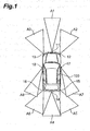
- a host vehicle 100 and a radar cruise control system 10 which is mounted in the host vehicle 100 include a front area millimeter-wave radar 11, a front right side millimeter-wave radar 12, a front left side millimeter-wave radar 13, a rear area millimeter-wave radar 14, a rear right side millimeter-wave radar 15, a rear left side millimeter-wave radar 16, a right dead angle millimeter-wave radar 17, and a left dead angle millimeter-wave radar 18 which are used to monitor different monitoring areas A1 to A8.
- the radars including the front area millimeter-wave radar 11 and the like are used to detect obstacles around the host vehicle 100.
- a millimeter-wave radar is a sensor which irradiates an electromagnetic wave, such as a millimeter wave, on a monitoring area, receives a reflected wave reflected by an object, and detects the speed, acceleration, distance, inter-vehicle time, and the like of an obstacle, such as another vehicle.
- an image sensor such as a camera, a laser radar, or the like may be applied.
- the radar cruise control system 10 includes a vehicle speed sensor 21, a yaw rate sensor 22, a wheel steering angle sensor 23, and a lane recognition sensor 24 which are used to detect the motion of the host vehicle 100.
- the lane recognition sensor 24 is used to recognize line markings (hereinafter, abbreviated as white lines) on a road, and to detect the traveling position of the host vehicle 100 in a lane.
- the lane recognition sensor 24 is an image sensor, such as a camera. Meanwhile, for the lane recognition sensor 24, a laser radar or the like may be applied.
- the radar cruise control system 10 includes a winker signal sensor 24, a brake signal sensor 25, and a driver line-of-sight sensor 26 which are used to detect the intention of the behavior of the driver.
- the winker signal sensor 24 and the brake signal sensor 25 are respectively used to detect the states of a winker operation and a brake operation by the driver.
- the driver line-of-sight sensor 25 is a sensor which performs pattern recognition on the image of the head portion of the driver captured by a camera or the like, and detects the movement of the eye and the method of sight of the driver.
- the wheel steering angle sensor 23 is also appropriately used.
- the radar cruise control system 10 includes an obstacle detection method determination ECU (Electronic Control Unit) 41.
- the obstacle detection method determination ECU 41 sets priority on the front area millimeter-wave radar 11 to the left dead angle millimeter-wave radar 18 on the basis of information acquired by the front area millimeter-wave radar 11, and various sensors including the vehicle speed sensor 21, the winker signal sensor 31, and the like.
- the obstacle detection method determination ECU 41 is used to control one of the operation of the front area millimeter-wave radar 11 to the left dead angle millimeter-wave radar. 18 and the processing of information output from the front area millimeter-wave radar 11 to the left dead angle millimeter-wave radar 18 on the basis of the set priority. For this reason, a command signal from the obstacle detection method determination ECU 41 is fed back to the front area millimeter-wave radar 11 to the left dead angle millimeter-wave radar 18.
- An autonomous driving/driving support ECU 51 is used to perform, on the basis of information relating to obstacles around the host vehicle 100 output from the obstacle detection method determination ECU 41, autonomous driving such that the host vehicle autonomously travels on a road to a destination while automatically avoiding the obstacles, or driving support to provide the driver with notification of the approach of obstacles or the obstacle avoidance directions.
- the devices are connected to each other by an in-vehicle LAN or the like.
- the obstacle detection method determination ECU 41 resets the priority flags of the front area millimeter-wave radar 11 to the left dead angle millimeter-wave radar 18 to the initial values (S101).
- the obstacle detection method determination ECU 41 detects the traveling direction- or predicted traveling direction of the host vehicle 100 or the lane, in which the host vehicle 100 is currently traveling, and the lane, in which the host vehicle 100 will be traveling, from the motion of the host vehicle 100 detected by the vehicle speed sensor 21, the yaw rate sensor 22, the wheel steering angle sensor 23, and the lane recognition sensor 24, or the behavior of the driver of the host vehicle 100 detected by the winker signal sensor 24, the brake signal sensor 25, and the driver line-of-sight sensor 26 (S102).
- the obstacle detection method determination ECU 41 increments +1 in the priority flags of the front area millimeter-wave radar 11 and the rear area millimeter-wave radar 14 (S 103, S104).
- the obstacle detection method determination ECU 41 increments +1 in the priority flags of the front right side millimeter-wave radar 12, the rear right side millimeter-wave radar 15, and the right dead angle millimeter-wave radar 17 (S103, S105).
- the obstacle detection method determination ECU 41 increments +1 in the priority flags of the front left side millimeter-wave radar 13, the rear left side millimeter-wave radar 16, and the left dead angle millimeter-wave radar 18 (S103, S106).
- the obstacle detection method determination ECU 41 increments +1 in the priority flags of the front area millimeter-wave radar 11, the front right side millimeter-wave radar 12, and the front left side millimeter-wave radar 13 (S107, S108).
- the obstacle detection method determination ECU 41 increments +1 in the priority flags of the rear area millimeter-wave radar 14, the right side millimeter-wave radar 15, and the left side millimeter-wave radar 16 (S107, S109).
- the obstacle detection method determination ECU 41 rearranges the front area millimeter-wave radar 11 to the left dead angle millimeter-wave radar 18 in a decreasing order of the priority flag (S110).
- the obstacle detection method determination ECU 41 preferentially performs an information process in order from a radar having a large priority flag after S110 of Fig. 3 , and also controls the front area millimeter-wave radar 11 to the left dead angle millimeter-wave radar 18 by the following method in a connector A of Fig. 3 .
- the obstacle detection method determination ECU 41 determines the resolution of the detection value in accordance with the number of bits of C in each radar (S204). In this case, the obstacle detection method determination ECU 41 sends a control signal to each radar including the front area millimeter-wave radar 11 and the like, and increases or decreases the detection precision of each radar in accordance with the number of bits of C such that the larger C, the higher the detection precision of the radar. The obstacle detection method determination ECU 41 increases or decreases the period of processing information output from each radar including the front area millimeter-wave radar 11 and the like in accordance with the number of bits of C such that the larger C, the shorter the period of processing information.
- the vehicle surrounding monitor device 10 includes a plurality of front area millimeter-wave radar 11 to left dead angle millimeter-wave radar 18 which monitor different areas around the host vehicle 100, the vehicle speed sensor 21, the yaw rate sensor 22, the wheel steering angle sensor 23, and the lane recognition sensor 24 which detect the traveling state of the host vehicle 100, the winker signal sensor 31, the brake signal sensor 32, and the driver line-of-sight sensor 33 which detect the state of the driver of the host vehicle 100, and the obstacle detection method determination ECU 41 which controls one of the operation of the front area millimeter-wave radar 11 to the left dead angle millimeter-wave radar 18 and the processing of information output from the front area millimeter-wave radar 11 to the left dead angle millimeter-wave radar 18.
- the obstacle detection method determination ECU 41 sets priority on a plurality of front area millimeter-wave radar 11 to left dead angle millimeter-wave radar 18 on the basis of the traveling state of the host vehicle 100 and the state of the driver of the host vehicle 100 detected by the vehicle speed sensor 21, the winker signal sensor 31, and the like, and controls one of the operation of the front area millimeter-wave radar 11. to the left dead angle millimeter-wave radar 18 and the processing of information output from the front area millimeter-wave radar 11 to the left dead angle millimeter-wave radar 18.
- control differs between a radar having high priority and a radar having low priority, such that, even when a plurality of radars are used, it becomes possible to monitor the surroundings of the host vehicle 100 while reducing the load of the CPU or the in-vehicle LAN.
- the obstacle detection method determination ECU 41 sets higher priority on a radar, which monitors an important area near the traveling direction of the host vehicle 100, than a radar, which monitors a less important area apart from the traveling direction of the host vehicle 100, on the basis of the traveling state of the host vehicle 100 and the state of the driver of the host vehicle detected by the vehicle speed sensor 21, the winker signal sensor 31, and the like, thereby appropriately setting the priority in accordance with the importance of the radar.
- the obstacle detection method determination ECU 41 changes detection precision to be high for a radar having high priority. For this reason, a read having high priority performs monitoring with necessary high detection precision, and a radar having low priority performs monitoring with low detection precision placing a light load on the CPU or the in-vehicle LAN. Therefore, even when a plurality of radars are used, it becomes possible to monitor the surroundings of the host vehicle 100 while reducing the load of the CPU or the in-vehicle LAN.
- the obstacle detection method determination ECU 41 shortens the period of processing information output from the radar. For this reason, information from a radar having high priority is processed frequently in a necessary short period, and information from a radar having low priority is processed in a low and long period placing a light load on the CPU or the in-vehicle LAN. Therefore, even when a plurality of radars are used, it becomes possible to monitor the surroundings of the host vehicle 100 while reducing the load of the CPU or the in-vehicle LAN.
- the lane recognition sensor 24 detects one of the lane in which the host vehicle 100 is currently traveling and the lane in which the host vehicle 100 will be traveling, and the obstacle detection method determination ECU 41 sets higher priority on a radar, which monitors an important area near the lane, in which the host vehicle 100 is currently traveling, and the lane, in which the host vehicle 100 will be traveling, detected by the lane recognition sensor 24, than a radar, which monitors a less important area apart from the lane, in which the host vehicle 100 is currently traveling, and the lane, in which the host vehicle 100 will be traveling, detected by the lane recognition sensor 24. Therefore, even when a plurality of radars are used, it becomes possible to monitor the surroundings of the host vehicle 100 while reducing the load of the CPU or the in-vehicle LAN.
- the obstacle detection method determination ECU 41 detects an area being monitored by the driver of the host vehicle 100 by the driver line-of-sight sensor 33 (S301).
- the obstacle detection method determination ECU 41 determines a radar in the same direction as the direction being monitored by the driver from among the front area millimeter-wave radar 11 to the left dead angle millimeter-wave radar 18 (S302).
- a radar in the same direction as the direction being monitored by the driver can be regarded as a radar which monitors an area included in the line of sight of the driver.
- the obstacle detection method determination ECU 41 sets the priority flag of a radar in the direction being monitored by the driver from among the front area millimeter-wave radar 11 to the left dead angle millimeter-wave radar 18 to zero or decrements -1 in the priority flag of a radar in the direction being monitored by the driver (S303).
- the obstacle detection method determination ECU 41 and the autonomous driving/driving support ECU 51 perform the same process as in the first embodiment on the basis of the set priority flags.
- the obstacle detection method determination ECU 41 performs control such that the autonomous driving/driving support ECU 51 preferentially provides notification of a warning for an obstacle detected by a radar, which has a large priority flag and monitors an area not included in the line of sight of the driver of the host vehicle 100, over a warning for an obstacle detected by a radar, which has a small priority flag and monitors an area included in the line of sight of the driver of the host vehicle 100, on the basis of the set priority.
- a warning provides the driver with notification of the approach of obstacles or the obstacle avoidance directions by image display on a display or sound from a speaker or a buzzer.
- the driver line-of-sight sensor 33 detects the line of sight of the driver of the host vehicle 100
- the obstacle detection method determination ECU 41 set higher priority on a radar, which monitors an area not included in the line of sight of the driver of the host vehicle 100 and having a great need for monitoring, than a radar, which monitors an area included in the line of sight of the driver of the host vehicle 100 and having a less need for monitoring, on the basis of the line of sight of the driver of the host vehicle 100 detected by the driver line-of-sight sensor 33. Therefore, it is possible to appropriately set the priority in accordance with the need for monitoring.
- the obstacle detection method determination ECU 41 performs control such that the autonomous driving/driving support ECU 51 preferentially provides notification of a warning for an obstacle detected by a radar, which monitors an area not included in the line of sight of the driver of the host vehicle 100 and having a great need for warning notification, over a warning for an obstacle detected by a radar, which monitors an area included in the line of sight of the driver of the host vehicle 100 and having a less need for warning notification, on the basis of the line of sight of the driver of the host vehicle 100 detected by the driver line-of-sight sensor 33. Therefore, it is possible to appropriately provide notification of a warning in accordance with the need for warning notification while reducing the load of the CPU or the in-vehicle LAN.
- the invention can provide a vehicle surrounding monitor device and a method for monitoring surroundings used for a vehicle capable of monitoring the surroundings of a host vehicle using a plurality of monitoring sensors for monitoring different areas around the host vehicle while reducing the load of a CPU or an in-vehicle LAN.
Landscapes
- Engineering & Computer Science (AREA)
- Physics & Mathematics (AREA)
- Radar, Positioning & Navigation (AREA)
- Remote Sensing (AREA)
- General Physics & Mathematics (AREA)
- Computer Networks & Wireless Communication (AREA)
- Automation & Control Theory (AREA)
- Electromagnetism (AREA)
- Human Computer Interaction (AREA)
- Transportation (AREA)
- Mechanical Engineering (AREA)
- Traffic Control Systems (AREA)
Abstract
Description
- The present invention relates to a vehicle surrounding monitor device and a method for monitoring surroundings used for a vehicle. In particular, the present invention relates to a vehicle surrounding monitor device which uses a plurality of monitoring sensors for monitoring different areas around a vehicle, and to a method for monitoring surroundings used for a vehicle.
- In order to improve the safety or convenience of automobiles, systems, such as a pre-crash safety system (PCS) and a radar cruise control system (RCC), have been developed or put into production. Various systems, such as a system which performs control such that a host vehicle autonomously travels on a road to a destination while automatically avoiding obstacles and a system which provides a driver with notification of the approach of obstacles or the obstacle avoidance directions, have been suggested. For this reason, a technique which enables the recognition of information relating to obstacles, such as other vehicles which are traveling around the host vehicle, with satisfactory precision has become important.
- For example,
Patent Literature 1 describes a device which monitors the head portion or eye line of a driver of a vehicle, directs a sensor head portion to the line of sight of the driver, and detects vehicles, obstacles, and the like in a direction to which the driver pays attention, making it possible to cope with an unexpected event. - [Patent Literature 1] Japanese Unexamined Patent Application Publication No.
2001-126195 - However, according to the above-described technique, it is difficult to detect obstacles, such as other vehicles, which approach from a direction opposite to the direction in which the sensor head portion is directed. Accordingly, if the surroundings of the host vehicle are monitored using a plurality of cameras or sensors, such as radar, which are directed in different directions, the processing load of a CPU (Central Control Unit) increases due to an increase in the number of sensors, or the load of an in-vehicle LAN (Local Area Network) increase due to an increase in the amount of data. The increase in the load of the CPU or the in-vehicle LAN leads to trouble in appropriately performing an obstacle detection process or driving support based on the obstacle detection process.
- The invention has been finalized in consideration of the above-described situation, and an object of the invention is to provide a vehicle surrounding monitor device and a method for monitoring surroundings used for a vehicle capable of monitoring the surroundings of a host vehicle using a plurality of monitoring sensors for monitoring different areas around the host vehicle while reducing the load of a CPU or an in-vehicle LAN.
- The invention provides a vehicle surrounding monitor device. The vehicle surrounding monitor device includes a plurality of monitoring sensors which monitor different areas around a host vehicle, a state detection unit which detects one of the traveling state of the host vehicle and the state of a driver of the host vehicle, and a control unit which controls one of the operation of the monitoring sensors and the processing of information output from the monitoring sensors. The control unit sets priority on a plurality of monitoring sensors on the basis of one of the traveling state of the host vehicle and the state of the driver of the host vehicle detected by the state detection unit, and controls one of the operation of the monitoring sensors and the processing of information output from the monitoring sensors on the basis of the priority.
- With this configuration, the vehicle surrounding monitor device includes a plurality of monitoring sensors which monitor different areas around the host vehicle, the state detection unit which detects one of the traveling state of the host vehicle and the state of the driver of the host vehicle, and the control unit which controls one of the operation of the monitoring sensors and the processing of information output from the monitoring sensors. In this vehicle surrounding monitor device, the control unit sets priority on a plurality of monitoring sensors on the basis of one of the traveling state of the host vehicle and the state of the driver of the host vehicle detected by the state detection unit, and controls one of the operation of the monitoring sensors and the processing of information output from the monitoring sensors on the basis of the priority. For this reason, control differs between a monitoring sensor having high priority and a monitoring sensor having low priority. Therefore, even when a plurality of monitoring sensors are used, it becomes possible to monitor the surroundings of the host vehicle while reducing the load of the CPU or the in-vehicle LAN.
- In this case, the control unit may set higher priority on a monitoring sensor which monitors an area near the traveling direction of the host vehicle than a monitoring sensor which monitors an area apart from the traveling direction of the host vehicle on the basis of one of the traveling state of the host vehicle and the state of the driver of the host vehicle detected by the state detection unit.
- With this configuration, the control unit sets higher priority on a monitoring sensor which monitors an important area near the traveling direction of the host vehicle than a monitoring sensor which monitors a less important area apart from the traveling direction of the host vehicle on the basis of one of the traveling state of the host vehicle and the state of the driver of the host vehicle detected by the state detection unit. Therefore, it is possible to appropriately set priority in accordance with the importance of the monitoring sensors.
- The state detection unit may detect the line of sight of the driver of the host vehicle, and the control unit may set higher priority on a monitoring sensor which monitors an area not included in the line of sight of the driver of the host vehicle than a monitoring sensor which monitors an area not included in the line of sight of the driver of the host vehicle on the basis of the line of sight of the driver of the host vehicle detected by the state detection unit.
- With this configuration, the state detection unit detects the line of sight of the driver of the host vehicle, and the control unit sets higher priority on a monitoring sensor, which monitors an area not included in the line of sight of the driver of the host vehicle and having a great need for monitoring, than a monitoring sensor, which monitors an area included in the line of sight of the driver of the host vehicle and having a less need for monitoring, on the basis of the line of sight of the driver of the host vehicle detected by the state detection unit. Therefore, it is possible to appropriately set priority in accordance with the need for monitoring.
- In this case, the vehicle surrounding monitor device may further include a warning notification unit which provides notification of a warning for an obstacle detected by the monitoring sensors to the driver of the host vehicle. The control unit may perform control such that the warning notification unit preferentially provides notification of a warning for an obstacle detected by a monitoring sensor, which monitors an area not included in the line of sight of the driver of the host vehicle, over a warning for an obstacle detected by a monitoring sensor, which monitors an area included in the line of sight of the driver of the host vehicle, on the basis of the line of sight of the driver of the host vehicle detected by the state detection unit.
- With this configuration, the vehicle surrounding monitor device further includes the warning notification unit which provides notification of a warning for an obstacle detected by the monitoring sensors to the driver of the host vehicle. The control unit performs control such that the warning notification unit preferentially provides notification of a warning for an obstacle detected by a monitoring sensor, which monitors an area not included in the line of sight of the driver of the host vehicle and having a great need for warning notification, over a warning for an obstacle detected by a monitoring sensor, which monitors an area included in the line of sight of the driver of the host vehicle and having a less need for warning notification, on the basis of the line of sight of the driver of the host vehicle detected by the state detection unit. Therefore, it is possible to appropriately provide notification of a warning in accordance with the need for warning notification while reducing the load of the CPU or the in-vehicle LAN.
- The control unit may change detection precision to be high for a monitoring sensor having high priority.
- With this configuration, the control unit changes detection precision to be high for a monitoring sensor having high priority. For this reason, a monitoring sensor having high priority performs monitoring with necessary high detection precision, and a monitoring sensor having low priority performs monitoring with low detection precision placing a light load on the CPU or the in-vehicle LAN. Therefore, even when a plurality of monitoring sensors are used, it becomes possible to monitor the surroundings of the host vehicle while reducing the load of the CPU or the in-vehicle LAN.
- For a monitoring sensor having high priority, the control unit may shorten the period of processing information output from the monitoring sensor.
- With this configuration, for a monitoring sensor having high priority, the control unit shortens the period of processing information output from the monitoring sensor. For this reason, information from a monitoring sensor having high priority is processed frequently in a necessary short period, and information from a monitoring sensor having low priority is processed in a low and long period placing a light load on the CPU or the in-vehicle LAN. Therefore, even when a plurality of monitoring sensors are used, it becomes possible to monitor the surroundings of the host vehicle while reducing the load of the CPU or the in-vehicle LAN.
- The state detection unit may detect one of a lane in which the host vehicle is currently traveling and a lane in which the host vehicle will be traveling, and the control unit may set higher priority on a monitoring sensor, which monitors an area near one of the lane, in which the host vehicle is currently traveling, and the lane, in which the host vehicle will be traveling, detected by the state detection unit, than a monitoring sensor, which monitors an area apart from one of the lane, in which the host vehicle is currently traveling, and the lane, in which the host vehicle will be traveling, detected by the state detection unit.
- With this configuration, the state detection unit detects one of the lanes in which the host vehicle is currently traveling and the line in which the host vehicle will be traveling, and the control unit sets higher priority on a monitoring sensor, which monitors an important area near one of the lane, in which the host vehicle is currently traveling, and the lane, in which the host vehicle will be traveling, detected by the state detection unit, than a monitoring sensor, which monitors a less important area apart from one of the lane, in which the host vehicle is currently traveling, and the lane, in which the host vehicle will be traveling, detected by the state detection unit. Therefore, even when a plurality of monitoring sensors are used, it becomes possible to monitor the surroundings of the host vehicle while reducing the load of the CPU or the in-vehicle LAN.
- The invention provides a method for monitoring surroundings used for a vehicle. The method includes the steps of causing a plurality of monitoring sensors to monitor different areas around a host vehicle, causing a state detection unit to detect one of the traveling state of the host vehicle and the state of a driver of the host vehicle, causing a control unit to set priority on a plurality of monitoring sensor on the basis of one of the traveling state of the host vehicle and the state of the driver of the host vehicle detected by the state detection unit, and causing the control unit to control one of the operation of the monitoring sensors and the processing of information output from the monitoring sensors on the basis of the set priority.
- In this case, in the step of causing the control unit to set priority on a plurality of monitoring sensors, the control unit may set higher priority on a monitoring sensor which monitors an area near the traveling direction of the host vehicle than a monitoring sensor which monitors an area apart from the traveling direction of the host vehicle on the basis of one of the traveling state of the host vehicle and the state of the driver of the host vehicle detected by the state detection unit.
- In the step of causing the state detection unit to detect one of the traveling state of the host vehicle and the state of the driver of the host vehicle, the state detection unit may detect the line of sight of the driver of the host vehicle, and in the step of causing the control unit to set priority on a plurality of monitoring sensors, the control unit may set higher priority on a monitoring sensor, which monitors an area not included in the line of sight of the driver of the host vehicle, than a monitoring sensor, which monitors an area included in the line of sight of the driver of the host vehicle, on the basis of the line of sight of the driver of the host vehicle detected by the state detection unit.
- In this case, the method may further include the step of causing a warning notification unit to provide notification of a warning for an obstacle detected by the monitoring sensors to the driver of the host vehicle. In the step of causing the warning notification unit to provide notification of a warning, the control unit may perform control such that the warning notification unit preferentially provides notification of a warning for an obstacle detected by a monitoring sensor, which monitors an area not included in the line of sight of the driver of the host vehicle, over a warning for an obstacle detected by a monitoring sensor, which monitors an area included in the line of sight of the driver of the host vehicle, on the basis of the line of sight of the driver of the host vehicle detected by the state detection unit.
- In the step of causing the control unit to control one of the operation of the monitoring sensors and the processing of information output from the monitoring sensors on the basis of the set priority, the control unit may change detection precision to be high for a monitoring sensor having high priority.
- In the step of causing the control unit to control one of the operation of the monitoring sensors and the processing of information output from the monitoring sensors on the basis of the set priority, for a monitoring sensor having high priority, the control unit may shorten the period of processing information output from the monitoring sensor.
- In the step of causing the state detection unit to detect one of the traveling state of the host vehicle and the state of the driver of the host vehicle, the state detection unit may detect one of a lane in which the host vehicle is currently traveling and a lane in which the host vehicle will be traveling, and in the step of causing the control unit to set priority on a plurality of monitoring sensors, the control unit may set higher priority on a monitoring sensor, which monitors an area near one of the lane, in which the host vehicle is currently traveling, and the lane, in which the host vehicle will be traveling, detected by the state detection unit, than a monitoring sensor, which monitors an area apart from one of the lane, in which the host vehicle is currently traveling, and the lane, in which the host vehicle will be traveling, detected by the state detection unit.
- According to the vehicle surrounding monitor device and the method for monitoring surroundings used for a vehicle of the invention, it becomes possible to monitor the surroundings of the host vehicle using a plurality of monitoring sensors for monitoring different areas around the host vehicle while reducing the load of the CPU or the in-vehicle LAN.
-
-
Fig. 1 is a plan view showing the monitoring range of each radar of a vehicle in which a radar cruise control system according to a first embodiment is mounted. -
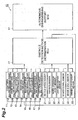
Fig. 2 is a block diagram showing the configuration of the radar cruise control system according to the first embodiment. -
Fig. 3 is a flowchart showing an operation to set priority of each radar. -
Fig. 4 is a flowchart showing an operation to set the resolution of a detection value of each radar in accordance with the priority of each radar in a connector A ofFig. 3 . -
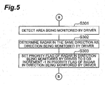
Fig. 5 is a flowchart showing an operation to set priority of each radar in accordance with an area being monitored by a driver in a connector B ofFig. 3 . - Hereinafter, a vehicle surrounding monitor device and a method for monitoring surroundings used for a vehicle according to an embodiment of the invention will be described with reference to the drawings.
- In a first embodiment of the invention, the vehicle surrounding monitor device of a vehicle according to the invention is applied to a radar cruise control system. The radar cruise control system is also called an ACC (Adaptive Cruise Control) system, and performs ACC control such that a host vehicle is traveling in accordance with one of a set vehicle speed and a set inter-vehicle distance (inter-vehicle time) from a preceding vehicle, thereby supporting the driving operation of a driver.
- As shown in
Figs. 1 and2 , in this embodiment, ahost vehicle 100 and a radarcruise control system 10 which is mounted in thehost vehicle 100 include a front area millimeter-wave radar 11, a front right side millimeter-wave radar 12, a front left side millimeter-wave radar 13, a rear area millimeter-wave radar 14, a rear right side millimeter-wave radar 15, a rear left side millimeter-wave radar 16, a right dead angle millimeter-wave radar 17, and a left dead angle millimeter-wave radar 18 which are used to monitor different monitoring areas A1 to A8. - The radars including the front area millimeter-
wave radar 11 and the like are used to detect obstacles around thehost vehicle 100. A millimeter-wave radar is a sensor which irradiates an electromagnetic wave, such as a millimeter wave, on a monitoring area, receives a reflected wave reflected by an object, and detects the speed, acceleration, distance, inter-vehicle time, and the like of an obstacle, such as another vehicle. Instead of a millimeter-wave radar, an image sensor, such as a camera, a laser radar, or the like may be applied. - As shown in
Fig. 2 , the radarcruise control system 10 includes avehicle speed sensor 21, ayaw rate sensor 22, a wheelsteering angle sensor 23, and alane recognition sensor 24 which are used to detect the motion of thehost vehicle 100. Thelane recognition sensor 24 is used to recognize line markings (hereinafter, abbreviated as white lines) on a road, and to detect the traveling position of thehost vehicle 100 in a lane. Specifically, thelane recognition sensor 24 is an image sensor, such as a camera. Meanwhile, for thelane recognition sensor 24, a laser radar or the like may be applied. - The radar
cruise control system 10 includes awinker signal sensor 24, a brake signal sensor 25, and a driver line-of-sight sensor 26 which are used to detect the intention of the behavior of the driver. Thewinker signal sensor 24 and the brake signal sensor 25 are respectively used to detect the states of a winker operation and a brake operation by the driver. Specifically, the driver line-of-sight sensor 25 is a sensor which performs pattern recognition on the image of the head portion of the driver captured by a camera or the like, and detects the movement of the eye and the method of sight of the driver. As a device which is used to detect the intention of the behavior of the driver, the wheelsteering angle sensor 23 is also appropriately used. - The radar
cruise control system 10 includes an obstacle detection method determination ECU (Electronic Control Unit) 41. The obstacle detectionmethod determination ECU 41 sets priority on the front area millimeter-wave radar 11 to the left dead angle millimeter-wave radar 18 on the basis of information acquired by the front area millimeter-wave radar 11, and various sensors including thevehicle speed sensor 21, thewinker signal sensor 31, and the like. The obstacle detectionmethod determination ECU 41 is used to control one of the operation of the front area millimeter-wave radar 11 to the left dead angle millimeter-wave radar. 18 and the processing of information output from the front area millimeter-wave radar 11 to the left dead angle millimeter-wave radar 18 on the basis of the set priority. For this reason, a command signal from the obstacle detectionmethod determination ECU 41 is fed back to the front area millimeter-wave radar 11 to the left dead angle millimeter-wave radar 18. - An autonomous driving/
driving support ECU 51 is used to perform, on the basis of information relating to obstacles around thehost vehicle 100 output from the obstacle detectionmethod determination ECU 41, autonomous driving such that the host vehicle autonomously travels on a road to a destination while automatically avoiding the obstacles, or driving support to provide the driver with notification of the approach of obstacles or the obstacle avoidance directions. The devices are connected to each other by an in-vehicle LAN or the like. - Hereinafter, the operation of the radar
cruise control system 10 of this embodiment will be described. The following steps are repeatedly performed for 10 milliseconds to 1 second during traveling of thehost vehicle 100. The obstacle detectionmethod determination ECU 41 resets the priority flags of the front area millimeter-wave radar 11 to the left dead angle millimeter-wave radar 18 to the initial values (S101). - The obstacle detection
method determination ECU 41 detects the traveling direction- or predicted traveling direction of thehost vehicle 100 or the lane, in which thehost vehicle 100 is currently traveling, and the lane, in which thehost vehicle 100 will be traveling, from the motion of thehost vehicle 100 detected by thevehicle speed sensor 21, theyaw rate sensor 22, the wheelsteering angle sensor 23, and thelane recognition sensor 24, or the behavior of the driver of thehost vehicle 100 detected by thewinker signal sensor 24, the brake signal sensor 25, and the driver line-of-sight sensor 26 (S102). - When the determination result on whether the traveling direction is left or right is the straight direction, the obstacle detection
method determination ECU 41 increments +1 in the priority flags of the front area millimeter-wave radar 11 and the rear area millimeter-wave radar 14 (S 103, S104). When the determination result on whether the traveling direction is left or right is the right direction, the obstacle detectionmethod determination ECU 41 increments +1 in the priority flags of the front right side millimeter-wave radar 12, the rear right side millimeter-wave radar 15, and the right dead angle millimeter-wave radar 17 (S103, S105). When the determination result on whether the traveling direction is left or right is the left direction, the obstacle detectionmethod determination ECU 41 increments +1 in the priority flags of the front left side millimeter-wave radar 13, the rear left side millimeter-wave radar 16, and the left dead angle millimeter-wave radar 18 (S103, S106). - When the determination result on whether the traveling direction is front or rear is acceleration, the obstacle detection
method determination ECU 41 increments +1 in the priority flags of the front area millimeter-wave radar 11, the front right side millimeter-wave radar 12, and the front left side millimeter-wave radar 13 (S107, S108). When the determination result on whether the traveling direction is front or rear is deceleration, the obstacle detectionmethod determination ECU 41 increments +1 in the priority flags of the rear area millimeter-wave radar 14, the right side millimeter-wave radar 15, and the left side millimeter-wave radar 16 (S107, S109). - The obstacle detection
method determination ECU 41 rearranges the front area millimeter-wave radar 11 to the left dead angle millimeter-wave radar 18 in a decreasing order of the priority flag (S110). - The obstacle detection
method determination ECU 41 preferentially performs an information process in order from a radar having a large priority flag after S110 ofFig. 3 , and also controls the front area millimeter-wave radar 11 to the left dead angle millimeter-wave radar 18 by the following method in a connector A ofFig. 3 . - As shown in
Fig. 4 , the obstacle detectionmethod determination ECU 41 calculates the total value A of the priority flags of the radars (S201). For example, when it is assumed that thehost vehicle 100 includes only three radars of the front area millimeter-wave radar 11, the front right side millimeter-wave radar 12, and the front left side millimeter-wave radar 13, if the priority flag of the front area millimeter-wave radar 11 is 3, the priority flag of the front right side millimeter-wave radar 12 is 2, and the priority flag of the front left side millimeter-wave radar 13 is 1, the total value A of the priority flags becomes A=3+2+1=6, - The obstacle detection
method determination ECU 41 calculates B={(the number of bits allocated to the obstacle detection process/A} (S202). For example, if the number of bits allocated to the obstacle detection process is 24 bits per unit time, in the above-described example, since A=6, B=24/6=4. - The obstacle detection
method determination ECU 41 calculates C={(the priority flag of each radar)×A} (S203). In the above-described example, C of the front area millimeter-wave radar 11 becomes C=3×4=12, C of the front right side millimeter-wave radar 12 becomes C=2×4=8, and C of the front left side millimeter-wave radar 13 becomes C=1×4=4. - The obstacle detection
method determination ECU 41 determines the resolution of the detection value in accordance with the number of bits of C in each radar (S204). In this case, the obstacle detectionmethod determination ECU 41 sends a control signal to each radar including the front area millimeter-wave radar 11 and the like, and increases or decreases the detection precision of each radar in accordance with the number of bits of C such that the larger C, the higher the detection precision of the radar. The obstacle detectionmethod determination ECU 41 increases or decreases the period of processing information output from each radar including the front area millimeter-wave radar 11 and the like in accordance with the number of bits of C such that the larger C, the shorter the period of processing information. - According to this embodiment, the vehicle surrounding
monitor device 10 includes a plurality of front area millimeter-wave radar 11 to left dead angle millimeter-wave radar 18 which monitor different areas around thehost vehicle 100, thevehicle speed sensor 21, theyaw rate sensor 22, the wheelsteering angle sensor 23, and thelane recognition sensor 24 which detect the traveling state of thehost vehicle 100, thewinker signal sensor 31, thebrake signal sensor 32, and the driver line-of-sight sensor 33 which detect the state of the driver of thehost vehicle 100, and the obstacle detectionmethod determination ECU 41 which controls one of the operation of the front area millimeter-wave radar 11 to the left dead angle millimeter-wave radar 18 and the processing of information output from the front area millimeter-wave radar 11 to the left dead angle millimeter-wave radar 18. The obstacle detectionmethod determination ECU 41 sets priority on a plurality of front area millimeter-wave radar 11 to left dead angle millimeter-wave radar 18 on the basis of the traveling state of thehost vehicle 100 and the state of the driver of thehost vehicle 100 detected by thevehicle speed sensor 21, thewinker signal sensor 31, and the like, and controls one of the operation of the front area millimeter-wave radar 11. to the left dead angle millimeter-wave radar 18 and the processing of information output from the front area millimeter-wave radar 11 to the left dead angle millimeter-wave radar 18. Therefore, control differs between a radar having high priority and a radar having low priority, such that, even when a plurality of radars are used, it becomes possible to monitor the surroundings of thehost vehicle 100 while reducing the load of the CPU or the in-vehicle LAN. - In this embodiment, the obstacle detection
method determination ECU 41 sets higher priority on a radar, which monitors an important area near the traveling direction of thehost vehicle 100, than a radar, which monitors a less important area apart from the traveling direction of thehost vehicle 100, on the basis of the traveling state of thehost vehicle 100 and the state of the driver of the host vehicle detected by thevehicle speed sensor 21, thewinker signal sensor 31, and the like, thereby appropriately setting the priority in accordance with the importance of the radar. - In this embodiment, the obstacle detection
method determination ECU 41 changes detection precision to be high for a radar having high priority. For this reason, a read having high priority performs monitoring with necessary high detection precision, and a radar having low priority performs monitoring with low detection precision placing a light load on the CPU or the in-vehicle LAN. Therefore, even when a plurality of radars are used, it becomes possible to monitor the surroundings of thehost vehicle 100 while reducing the load of the CPU or the in-vehicle LAN. - In this embodiment, for a radar having high priority, the obstacle detection
method determination ECU 41 shortens the period of processing information output from the radar. For this reason, information from a radar having high priority is processed frequently in a necessary short period, and information from a radar having low priority is processed in a low and long period placing a light load on the CPU or the in-vehicle LAN. Therefore, even when a plurality of radars are used, it becomes possible to monitor the surroundings of thehost vehicle 100 while reducing the load of the CPU or the in-vehicle LAN. - In this embodiment, the
lane recognition sensor 24 detects one of the lane in which thehost vehicle 100 is currently traveling and the lane in which thehost vehicle 100 will be traveling, and the obstacle detectionmethod determination ECU 41 sets higher priority on a radar, which monitors an important area near the lane, in which thehost vehicle 100 is currently traveling, and the lane, in which thehost vehicle 100 will be traveling, detected by thelane recognition sensor 24, than a radar, which monitors a less important area apart from the lane, in which thehost vehicle 100 is currently traveling, and the lane, in which thehost vehicle 100 will be traveling, detected by thelane recognition sensor 24. Therefore, even when a plurality of radars are used, it becomes possible to monitor the surroundings of thehost vehicle 100 while reducing the load of the CPU or the in-vehicle LAN. - Hereinafter, a second embodiment of the invention will be described. In this embodiment, the following process is performed in a connector B of
Fig. 3 . As shown inFig. 5 , the obstacle detectionmethod determination ECU 41 detects an area being monitored by the driver of thehost vehicle 100 by the driver line-of-sight sensor 33 (S301). - The obstacle detection
method determination ECU 41 determines a radar in the same direction as the direction being monitored by the driver from among the front area millimeter-wave radar 11 to the left dead angle millimeter-wave radar 18 (S302). A radar in the same direction as the direction being monitored by the driver can be regarded as a radar which monitors an area included in the line of sight of the driver. - The obstacle detection
method determination ECU 41 sets the priority flag of a radar in the direction being monitored by the driver from among the front area millimeter-wave radar 11 to the left dead angle millimeter-wave radar 18 to zero or decrements -1 in the priority flag of a radar in the direction being monitored by the driver (S303). The obstacle detectionmethod determination ECU 41 and the autonomous driving/driving support ECU 51 perform the same process as in the first embodiment on the basis of the set priority flags. - The obstacle detection
method determination ECU 41 performs control such that the autonomous driving/driving support ECU 51 preferentially provides notification of a warning for an obstacle detected by a radar, which has a large priority flag and monitors an area not included in the line of sight of the driver of thehost vehicle 100, over a warning for an obstacle detected by a radar, which has a small priority flag and monitors an area included in the line of sight of the driver of thehost vehicle 100, on the basis of the set priority. Specifically, a warning provides the driver with notification of the approach of obstacles or the obstacle avoidance directions by image display on a display or sound from a speaker or a buzzer. - In this embodiment, the driver line-of-
sight sensor 33 detects the line of sight of the driver of thehost vehicle 100, and the obstacle detectionmethod determination ECU 41 set higher priority on a radar, which monitors an area not included in the line of sight of the driver of thehost vehicle 100 and having a great need for monitoring, than a radar, which monitors an area included in the line of sight of the driver of thehost vehicle 100 and having a less need for monitoring, on the basis of the line of sight of the driver of thehost vehicle 100 detected by the driver line-of-sight sensor 33. Therefore, it is possible to appropriately set the priority in accordance with the need for monitoring. - In this embodiment, the obstacle detection
method determination ECU 41 performs control such that the autonomous driving/driving support ECU 51 preferentially provides notification of a warning for an obstacle detected by a radar, which monitors an area not included in the line of sight of the driver of thehost vehicle 100 and having a great need for warning notification, over a warning for an obstacle detected by a radar, which monitors an area included in the line of sight of the driver of thehost vehicle 100 and having a less need for warning notification, on the basis of the line of sight of the driver of thehost vehicle 100 detected by the driver line-of-sight sensor 33. Therefore, it is possible to appropriately provide notification of a warning in accordance with the need for warning notification while reducing the load of the CPU or the in-vehicle LAN. - Although the embodiments of the invention have been described, the invention is not limited to the foregoing embodiments, and various modifications may be made.
- The invention can provide a vehicle surrounding monitor device and a method for monitoring surroundings used for a vehicle capable of monitoring the surroundings of a host vehicle using a plurality of monitoring sensors for monitoring different areas around the host vehicle while reducing the load of a CPU or an in-vehicle LAN.
-
- 10:
- radar cruise control system
- 11:
- front area millimeter-wave radar
- 12:
- front right side millimeter-wave radar
- 13:
- front left side millimeter-wave radar
- 14:
- rear area millimeter-wave radar
- 15:
- rear right side millimeter-wave radar
- 16:
- rear left side millimeter-wave radar
- 17:
- right dead angle millimeter-wave radar
- 18:
- left dead angle millimeter-wave radar
- 21:
- vehicle speed sensor
- 22:
- yaw rate sensor
- 23:
- wheel steering angle sensor
- 24:
- lane recognition sensor
- 31:
- winker signal sensor
- 32:
- brake signal sensor
- 33:
- driver line-of-sight sensor
- 41:
- obstacle detection direction determination ECU
- 51:
- autonomous driving/driving support ECU
Claims (14)
- A vehicle surrounding monitor device comprising:a plurality of monitoring sensors which monitor different areas around a host vehicle;a state detection unit which detects one of the traveling state of the host vehicle and the state of a driver of the host vehicle; anda control unit which controls one of the operation of the monitoring sensors and processing of information output from the monitoring sensors,wherein the control unit sets priority on a plurality of monitoring sensors on the basis of one of the traveling state of the host vehicle and the state of the driver of the host vehicle detected by the state detection unit, and controls one of the operation of the monitoring sensors and the processing of information output from the monitoring sensors on the basis of the priority.
- The vehicle surrounding monitor device according to claim 1,
wherein the control unit sets higher priority on a monitoring sensor which monitors an area near the traveling direction of the host vehicle than a monitoring sensor which monitors an area apart from the traveling direction of the host vehicle on the basis of one of the traveling state of the host vehicle and the state of the driver of the host vehicle detected by the state detection unit. - The vehicle surrounding monitor device according to claim 1 or 2,
wherein the state detection unit detects the line of sight of the driver of the host vehicle, and
wherein the control unit sets higher priority on a monitoring sensor, which monitors an area not included in the line of sight of the driver of the host vehicle, than a monitoring sensor, which monitors an area included in the line of sight of the driver of the host vehicle, on the basis of the line of sight of the driver of the host vehicle detected by the state detection unit. - The vehicle surrounding monitor device according to claim 3, further comprising:a warning notification unit which provides notification of a warning for an obstacle detected by the monitoring sensors to the driver of the host vehicle,wherein the control unit performs control such that the warning notification unit preferentially provides notification of a warning for an obstacle detected by a monitoring sensor, which monitors an area not included in the line of sight of the driver of the host vehicle, over a warning for an obstacle detected by a monitoring sensor, which monitors an area included in the line of sight of the driver of the host vehicle, on the basis of the line of sight of the driver of the host vehicle detected by the state detection unit.
- The vehicle surrounding monitor device according to any one of claims 1 to 4,
wherein the control unit changes detection precision to be high for a monitoring sensor having high priority. - The vehicle surrounding monitor device according to any one of claims 1 to 5,
wherein, for a monitoring sensor having high priority, the control unit shortens the period of processing information output from the monitoring sensor. - The vehicle surrounding monitor device according to any one of claims 1 to 6,
wherein the state detection unit detects one of a lane in which the host vehicle is currently traveling and a lane in which the host vehicle will be traveling,
the control unit sets higher priority on a monitoring sensor, which monitors an area near one of the lane, in which the host vehicle is currently traveling, and the lane, in which the host vehicle will be traveling, detected by the state detection unit, than a monitoring sensor, which monitors an area apart from one of the lane, in which the host vehicle is currently traveling, and the lane, in which the host vehicle will be traveling, detected by the state detection unit. - A method for monitoring surroundings used for a vehicle, the method comprising the steps of:causing a plurality of monitoring sensors to monitor different areas around a host vehicle;causing a state detection unit to detect one of the traveling state of the host vehicle and the state of a driver of the host vehicle;causing a control unit to set priority on a plurality of monitoring sensor on the basis of one of the traveling state of the host vehicle and the state of the driver of the host vehicle detected by the state detection unit; andcausing the control unit to control one of the operation of the monitoring sensors and processing of information output from the monitoring sensors on the basis of the set priority.
- The method according to claim 8,
wherein, in the step of causing the control unit to set priority on a plurality of monitoring sensors, the control unit sets higher priority on a monitoring sensor which monitors an area near the traveling direction of the host vehicle than a monitoring sensor which monitors an area apart from the traveling direction of the host vehicle on the basis of one of the traveling state of the host vehicle and the state of the driver of the host vehicle detected by the state detection unit. - The method according to claim 8 or 9,
wherein, in the step of causing the state detection unit to detect one of the traveling state of the host vehicle and the state of the driver of the host vehicle, the state detection unit detects the line of sight of the driver of the host vehicle, and
in the step of causing the control unit to set priority on a plurality of monitoring sensors, the control unit sets higher priority on a monitoring sensor, which monitors an area not included in the line of sight of the driver of the host vehicle, than a monitoring sensor, which monitors an area included in the line of sight of the driver of the host vehicle, on the basis of the line of sight of the driver of the host vehicle detected by the state detection unit. - The method according to claim 10, further comprising the step of:causing a warning notification unit to provide notification of a warning for an obstacle detected by the monitoring sensors to the driver of the host vehicle,wherein, in the step of causing the warning notification unit to provide notification of a warning, the control unit performs control such that the warning notification unit preferentially provides notification of a warning for an obstacle detected by a monitoring sensor, which monitors an area not included in the line of sight of the driver of the host vehicle, over a warning for an obstacle detected by a monitoring sensor, which monitors an area included in the line of sight of the driver of the host vehicle, on the basis of the line of sight of the driver of the host vehicle detected by the state detection unit.
- The method according to any one of claims 8 to 11,
wherein, in the step of causing the control unit to control one of the operation of the monitoring sensors and the processing of information output from the monitoring sensors on the basis of the set priority, the control unit changes detection precision to be high for a monitoring sensor having high priority. - The method according to any one of claims 8 to 12,
wherein, in the step of causing the control unit to control one of the operation of the monitoring sensors and the processing of information output from the monitoring sensors on the basis of the set priority, for a monitoring sensor having high priority, the control unit may shorten the period of processing information output from the monitoring sensor. - The method according to any one of claims 8 to 13,
wherein, in the step of causing the state detection unit to detect one of the traveling state of the host vehicle and the state of the driver of the host vehicle, the state detection unit detects one of a lane in which the host vehicle is currently traveling and a lane in which the host vehicle will be traveling, and
in the step of causing the control unit to set priority on a plurality of monitoring sensors, the control unit sets higher priority on a monitoring sensor, which monitors an area near one of the lane, in which the host vehicle is currently traveling, and the lane, in which the host vehicle will be traveling, detected by the state detection unit, than a monitoring sensor, which monitors an area apart from one of the lane, in which the host vehicle is currently traveling, and the lane, in which the host vehicle will be traveling, detected by the state detection unit.
Applications Claiming Priority (1)
| Application Number | Priority Date | Filing Date | Title |
|---|---|---|---|
| PCT/JP2009/060278 WO2010140239A1 (en) | 2009-06-04 | 2009-06-04 | Vehicle surrounding monitor device and method for monitoring surroundings used for vehicle |
Publications (3)
| Publication Number | Publication Date |
|---|---|
| EP2439714A1 true EP2439714A1 (en) | 2012-04-11 |
| EP2439714A4 EP2439714A4 (en) | 2012-12-26 |
| EP2439714B1 EP2439714B1 (en) | 2015-03-18 |
Family
ID=43297385
Family Applications (1)
| Application Number | Title | Priority Date | Filing Date |
|---|---|---|---|
| EP09845524.9A Active EP2439714B1 (en) | 2009-06-04 | 2009-06-04 | Vehicle surrounding monitor device and method for monitoring surroundings used for vehicle |
Country Status (5)
| Country | Link |
|---|---|
| US (1) | US8676488B2 (en) |
| EP (1) | EP2439714B1 (en) |
| JP (1) | JP5327321B2 (en) |
| CN (1) | CN102439644B (en) |
| WO (1) | WO2010140239A1 (en) |
Cited By (7)
| Publication number | Priority date | Publication date | Assignee | Title |
|---|---|---|---|---|
| WO2016045794A1 (en) * | 2014-09-25 | 2016-03-31 | Audi Ag | Method for operating a multiplicity of radar sensors in a motor vehicle and motor vehicle |
| EP3100927A1 (en) * | 2011-02-18 | 2016-12-07 | Honda Motor Co., Ltd. | System and method for responding to driver behavior |
| DE102015011927B3 (en) * | 2015-09-12 | 2016-12-15 | Audi Ag | Method for reducing the energy consumption of radar sensors in a motor vehicle and motor vehicle |
| WO2017157787A1 (en) * | 2016-03-17 | 2017-09-21 | Audi Ag | Method for operating a driver assistance system of a motor vehicle and motor vehicle |
| EP3168750A4 (en) * | 2014-07-07 | 2018-03-07 | Hitachi Automotive Systems, Ltd. | Information processing system |
| FR3076789A1 (en) * | 2017-12-19 | 2019-07-19 | Robert Bosch Gmbh | "Process for processing sensor data of a vehicle" |
| US10752252B2 (en) | 2013-03-15 | 2020-08-25 | Honda Motor Co., Ltd. | System and method for responding to driver state |
Families Citing this family (45)
| Publication number | Priority date | Publication date | Assignee | Title |
|---|---|---|---|---|
| JP4254844B2 (en) * | 2006-11-01 | 2009-04-15 | トヨタ自動車株式会社 | Travel control plan evaluation device |
| CN102449672B (en) * | 2009-06-02 | 2013-05-01 | 丰田自动车株式会社 | Vehicular peripheral surveillance device |
| US20120050025A1 (en) * | 2010-08-26 | 2012-03-01 | Hoeffel James J | Vehicle steering assist system and method of operation |
| WO2013122030A1 (en) * | 2012-02-14 | 2013-08-22 | 日産自動車株式会社 | Travel control device and travel control method |
| JP5686123B2 (en) * | 2012-09-18 | 2015-03-18 | 株式会社デンソー | Vehicle detection device and alarm device |
| JP6128584B2 (en) * | 2013-01-16 | 2017-05-17 | 株式会社Soken | Travel route generator |
| DE102013201481A1 (en) * | 2013-01-30 | 2014-07-31 | Continental Teves Ag & Co. Ohg | A method for reducing an overall aggregate computing capacity, vehicle-to-X communication device and use of the vehicle-to-X communication device |
| US20150153184A1 (en) * | 2013-12-04 | 2015-06-04 | GM Global Technology Operations LLC | System and method for dynamically focusing vehicle sensors |
| CN104135650A (en) * | 2014-08-11 | 2014-11-05 | 四川沛阳科技有限公司 | Panoramic overlooking driving monitoring method with driving track prediction based on mobile terminal |
| JP6408832B2 (en) * | 2014-08-27 | 2018-10-17 | ルネサスエレクトロニクス株式会社 | Control system, relay device, and control method |
| DE102014225383A1 (en) * | 2014-12-10 | 2016-06-16 | Robert Bosch Gmbh | Method for operating a motor vehicle, motor vehicle |
| CN105835770A (en) * | 2015-01-15 | 2016-08-10 | 上海通用汽车有限公司 | Staged early warning system for vehicle |
| JP6176280B2 (en) * | 2015-03-30 | 2017-08-09 | トヨタ自動車株式会社 | Arrangement structure of surrounding information detection sensor and autonomous driving vehicle |
| JP6319349B2 (en) * | 2015-04-03 | 2018-05-09 | 株式会社デンソー | Information presentation device |
| JP6631776B2 (en) * | 2015-07-23 | 2020-01-15 | 三菱自動車工業株式会社 | Vehicle driving support device |
| US10493907B2 (en) | 2015-07-31 | 2019-12-03 | Hitachi Automotive Systems, Ltd. | Vehicle periphery information management device |
| JP6365481B2 (en) * | 2015-09-23 | 2018-08-01 | トヨタ自動車株式会社 | Vehicle travel control device |
| JP6387948B2 (en) * | 2015-12-11 | 2018-09-12 | トヨタ自動車株式会社 | Vehicle driving support device |
| WO2018105136A1 (en) * | 2016-12-06 | 2018-06-14 | 本田技研工業株式会社 | Vehicle surrounding information acquisition device and vehicle |
| US9898008B2 (en) | 2016-03-22 | 2018-02-20 | Delphi Technologies, Inc. | Scenario aware perception system for an automated vehicle |
| CN109074742B (en) * | 2016-04-20 | 2022-05-13 | 三菱电机株式会社 | Peripheral recognition device, peripheral recognition method, and computer-readable recording medium |
| JP6799805B2 (en) * | 2016-05-25 | 2020-12-16 | パナソニックIpマネジメント株式会社 | Object detectors, programs and recording media |
| CN106448190B (en) * | 2016-09-26 | 2023-03-17 | 长安大学 | Real-time monitoring and early warning device and method for traffic flow around self-vehicle on highway |
| JP6332384B2 (en) * | 2016-09-29 | 2018-05-30 | マツダ株式会社 | Vehicle target detection system |
| JP6654544B2 (en) | 2016-10-21 | 2020-02-26 | 株式会社Soken | Sensor control device |
| CN110291419A (en) | 2017-02-20 | 2019-09-27 | 三菱电机株式会社 | Sensor data integration device, sensor data integration method, and sensor data integration program |
| JP6935672B2 (en) * | 2017-03-03 | 2021-09-15 | 富士フイルムビジネスイノベーション株式会社 | Mobile device |
| WO2019017216A1 (en) * | 2017-07-21 | 2019-01-24 | ソニーセミコンダクタソリューションズ株式会社 | Vehicle control device and vehicle control method |
| JP6944308B2 (en) | 2017-08-18 | 2021-10-06 | ソニーセミコンダクタソリューションズ株式会社 | Control devices, control systems, and control methods |
| JP6791106B2 (en) * | 2017-12-06 | 2020-11-25 | 株式会社デンソー | Peripheral recognition device and peripheral recognition method |
| US10501085B2 (en) | 2017-12-07 | 2019-12-10 | Waymo Llc | Early object detection for unprotected turns |
| CN109017802B (en) * | 2018-06-05 | 2020-12-25 | 长沙智能驾驶研究院有限公司 | Intelligent driving environment perception method and device, computer equipment and storage medium |
| CN110696716A (en) * | 2018-07-09 | 2020-01-17 | 上海擎感智能科技有限公司 | Vehicle alarm method, vehicle alarm system, vehicle-mounted terminal and vehicle |
| JP7301865B2 (en) * | 2018-09-25 | 2023-07-03 | 日立Astemo株式会社 | electronic controller |
| WO2020075686A1 (en) | 2018-10-12 | 2020-04-16 | 京セラ株式会社 | Electronic device, method for controlling electronic device, and program for controlling electronic device |
| CN109407097B (en) * | 2018-10-30 | 2020-09-29 | 北京润科通用技术有限公司 | Method and device for detecting vehicle travelable area |
| TWI686747B (en) | 2018-11-29 | 2020-03-01 | 財團法人金屬工業研究發展中心 | Method for avoiding obstacles of mobile vehicles all week |
| JP7180421B2 (en) * | 2019-02-04 | 2022-11-30 | トヨタ自動車株式会社 | vehicle controller |
| CN110103824A (en) * | 2019-05-27 | 2019-08-09 | 王黎明 | A kind of auxiliary early warning system shown based on real time panoramic and its method for early warning |
| CN110422117A (en) * | 2019-08-14 | 2019-11-08 | 天津清智科技有限公司 | A kind of vehicle drive environment monitoring method |
| KR102352360B1 (en) * | 2020-03-13 | 2022-01-18 | 한양대학교 산학협력단 | Method and system for analysing obstacle using analysis priority for obstacle candidate based on attention of driver |
| KR20220082551A (en) * | 2020-12-10 | 2022-06-17 | 현대자동차주식회사 | Vehicle |
| CN112731375B (en) * | 2020-12-11 | 2024-09-13 | 北京龙飞船科技有限公司 | Regional detector capable of automatically adjusting sensitivity according to environmental change and method thereof |
| JP7634321B2 (en) * | 2021-08-17 | 2025-02-21 | パナソニックオートモーティブシステムズ株式会社 | OBJECT DETECTION SYSTEM AND OBJECT DETECTION METHOD |
| CN114495503A (en) * | 2022-01-29 | 2022-05-13 | 深圳智慧车联科技有限公司 | System and method for supervising right turning standard operation of muck truck |
Family Cites Families (19)
| Publication number | Priority date | Publication date | Assignee | Title |
|---|---|---|---|---|
| JP2689792B2 (en) * | 1991-10-30 | 1997-12-10 | 日産自動車株式会社 | Three-dimensional sound field alarm device |
| JP3676616B2 (en) * | 1999-04-28 | 2005-07-27 | 本田技研工業株式会社 | Obstacle detection device |
| JP2001126195A (en) | 1999-10-29 | 2001-05-11 | Mitsubishi Electric Corp | Safe driving support sensor |
| JP4152628B2 (en) * | 2001-12-25 | 2008-09-17 | アイシン・エィ・ダブリュ株式会社 | Other vehicle recognition device, other vehicle recognition method and program |
| JP2003329773A (en) * | 2002-05-10 | 2003-11-19 | Hitachi Ltd | Vehicle control device equipped with multiple distance detection sensors |
| JP3879610B2 (en) * | 2002-07-15 | 2007-02-14 | 株式会社デンソー | Obstacle detection device, program, and recording medium |
| JP2005056336A (en) * | 2003-08-07 | 2005-03-03 | Denso Corp | Vehicle periphery monitoring device |
| JP2005100337A (en) | 2003-09-01 | 2005-04-14 | Matsushita Electric Ind Co Ltd | Monitoring system and program thereof |
| JP4151540B2 (en) * | 2003-09-26 | 2008-09-17 | トヨタ自動車株式会社 | Vehicle travel control device |
| ITMO20040245A1 (en) * | 2004-09-24 | 2004-12-24 | Meta System Spa | OBSTACLE DETECTION SYSTEM AND METHOD IN PARTICULAR FOR VEHICLE PARKING FACILITATION SYSTEMS. |
| JP4305412B2 (en) | 2005-05-10 | 2009-07-29 | 株式会社デンソー | Obstacle detection device |
| DE102006019833B4 (en) | 2005-05-10 | 2013-04-11 | Denso Corporation | Device for discovering an obstacle |
| JP4752686B2 (en) * | 2006-09-01 | 2011-08-17 | トヨタ自動車株式会社 | Obstacle detection device for vehicles |
| JP5070809B2 (en) | 2006-11-10 | 2012-11-14 | アイシン精機株式会社 | Driving support device, driving support method, and program |
| JP5187194B2 (en) | 2006-11-21 | 2013-04-24 | 富士通株式会社 | Multiprocessor system |
| JP2008149860A (en) * | 2006-12-15 | 2008-07-03 | Toyota Motor Corp | Travel control device |
| JP4372804B2 (en) * | 2007-05-09 | 2009-11-25 | トヨタ自動車株式会社 | Image processing device |
| JP5110356B2 (en) | 2007-07-10 | 2012-12-26 | オムロン株式会社 | Detection apparatus and method, and program |
| JP2009086788A (en) | 2007-09-28 | 2009-04-23 | Hitachi Ltd | Vehicle periphery monitoring device |
-
2009
- 2009-06-04 EP EP09845524.9A patent/EP2439714B1/en active Active
- 2009-06-04 WO PCT/JP2009/060278 patent/WO2010140239A1/en not_active Ceased
- 2009-06-04 CN CN200980159363.7A patent/CN102439644B/en active Active
- 2009-06-04 US US13/321,326 patent/US8676488B2/en active Active
- 2009-06-04 JP JP2011518128A patent/JP5327321B2/en active Active
Cited By (16)
| Publication number | Priority date | Publication date | Assignee | Title |
|---|---|---|---|---|
| EP3100927A1 (en) * | 2011-02-18 | 2016-12-07 | Honda Motor Co., Ltd. | System and method for responding to driver behavior |
| US10752252B2 (en) | 2013-03-15 | 2020-08-25 | Honda Motor Co., Ltd. | System and method for responding to driver state |
| US11383721B2 (en) | 2013-03-15 | 2022-07-12 | Honda Motor Co., Ltd. | System and method for responding to driver state |
| US10780891B2 (en) | 2013-03-15 | 2020-09-22 | Honda Motor Co., Ltd. | System and method for responding to driver state |
| US10759436B2 (en) | 2013-03-15 | 2020-09-01 | Honda Motor Co., Ltd. | System and method for responding to driver state |
| US10759438B2 (en) | 2013-03-15 | 2020-09-01 | Honda Motor Co., Ltd. | System and method for responding to driver state |
| US10759437B2 (en) | 2013-03-15 | 2020-09-01 | Honda Motor Co., Ltd. | System and method for responding to driver state |
| EP3168750A4 (en) * | 2014-07-07 | 2018-03-07 | Hitachi Automotive Systems, Ltd. | Information processing system |
| US10306207B2 (en) | 2014-07-07 | 2019-05-28 | Hitachi Automotive Systems, Ltd. | Information processing system |
| US10451729B2 (en) | 2014-09-25 | 2019-10-22 | Audi Ag | Method for operating a multiplicity of radar sensors in a motor vehicle and motor vehicle |
| WO2016045794A1 (en) * | 2014-09-25 | 2016-03-31 | Audi Ag | Method for operating a multiplicity of radar sensors in a motor vehicle and motor vehicle |
| US10877149B2 (en) | 2014-09-25 | 2020-12-29 | Audi Ag | Method for operating a multiplicity of radar sensors in a motor vehicle and motor vehicle |
| DE102015011927B3 (en) * | 2015-09-12 | 2016-12-15 | Audi Ag | Method for reducing the energy consumption of radar sensors in a motor vehicle and motor vehicle |
| US10532770B2 (en) | 2016-03-17 | 2020-01-14 | Audi Ag | Method for operating a driver assistance system of a motor vehicle and motor vehicle |
| WO2017157787A1 (en) * | 2016-03-17 | 2017-09-21 | Audi Ag | Method for operating a driver assistance system of a motor vehicle and motor vehicle |
| FR3076789A1 (en) * | 2017-12-19 | 2019-07-19 | Robert Bosch Gmbh | "Process for processing sensor data of a vehicle" |
Also Published As
| Publication number | Publication date |
|---|---|
| EP2439714B1 (en) | 2015-03-18 |
| US20120065841A1 (en) | 2012-03-15 |
| US8676488B2 (en) | 2014-03-18 |
| JPWO2010140239A1 (en) | 2012-11-15 |
| WO2010140239A1 (en) | 2010-12-09 |
| EP2439714A4 (en) | 2012-12-26 |
| CN102439644B (en) | 2014-09-03 |
| CN102439644A (en) | 2012-05-02 |
| JP5327321B2 (en) | 2013-10-30 |
Similar Documents
| Publication | Publication Date | Title |
|---|---|---|
| US8676488B2 (en) | Vehicle surrounding monitor device and method for monitoring surroundings used for vehicle | |
| US11485357B2 (en) | Vehicle control device | |
| KR102715606B1 (en) | Advanced Driver Assistance System, Vehicle having the same and method for controlling the vehicle | |
| EP2671768B1 (en) | Vehicle control apparatus | |
| CN113246993B (en) | driving support system | |
| CN111942352B (en) | Adaptive AEB system considering steering path and control method thereof | |
| US10960878B2 (en) | Control device for vehicle and control method for vehicle | |
| EP2750118B1 (en) | Driving support apparatus and driving support method | |
| EP2757540B1 (en) | Driving assistance device and driving assistance method | |
| KR102695891B1 (en) | driver assistance apparatus | |
| US11518373B2 (en) | Vehicle and control method thereof | |
| US20200353919A1 (en) | Target detection device for vehicle | |
| US20200385021A1 (en) | Vehicle control apparatus, vehicle, operation method of vehicle control apparatus, and non-transitory computer-readable storage medium | |
| EP3796284B1 (en) | Ecu and lane departure warning system | |
| US11648937B2 (en) | Driver assistance device | |
| CN116729368A (en) | Collision avoidance device, collision avoidance method, and collision avoidance program product | |
| US20250249896A1 (en) | Vehicle control device | |
| US20240239314A1 (en) | Vehicle control apparatus | |
| JP2011076527A (en) | Travel safety device for vehicle | |
| KR102936876B1 (en) | Vehicle and control method thereof | |
| KR102762913B1 (en) | Vehicle and controlling method thereof | |
| KR20230000655A (en) | Vehicle and control method thereof | |
| JP4682823B2 (en) | Vehicle control system and vehicle control apparatus | |
| KR20230162166A (en) | driver assistance System and control method for the same |
Legal Events
| Date | Code | Title | Description |
|---|---|---|---|
| PUAI | Public reference made under article 153(3) epc to a published international application that has entered the european phase |
Free format text: ORIGINAL CODE: 0009012 |
|
| 17P | Request for examination filed |
Effective date: 20111117 |
|
| AK | Designated contracting states |
Kind code of ref document: A1 Designated state(s): AT BE BG CH CY CZ DE DK EE ES FI FR GB GR HR HU IE IS IT LI LT LU LV MC MK MT NL NO PL PT RO SE SI SK TR |
|
| DAX | Request for extension of the european patent (deleted) | ||
| A4 | Supplementary search report drawn up and despatched |
Effective date: 20121127 |
|
| RIC1 | Information provided on ipc code assigned before grant |
Ipc: G01S 13/87 20060101ALI20121120BHEP Ipc: B60R 21/00 20060101ALI20121120BHEP Ipc: G01S 13/93 20060101ALI20121120BHEP Ipc: B60W 50/06 20060101ALI20121120BHEP Ipc: G08G 1/16 20060101AFI20121120BHEP |
|
| RAP1 | Party data changed (applicant data changed or rights of an application transferred) |
Owner name: TOYOTA JIDOSHA KABUSHIKI KAISHA |
|
| GRAP | Despatch of communication of intention to grant a patent |
Free format text: ORIGINAL CODE: EPIDOSNIGR1 |
|
| INTG | Intention to grant announced |
Effective date: 20141014 |
|
| GRAS | Grant fee paid |
Free format text: ORIGINAL CODE: EPIDOSNIGR3 |
|
| GRAA | (expected) grant |
Free format text: ORIGINAL CODE: 0009210 |
|
| AK | Designated contracting states |
Kind code of ref document: B1 Designated state(s): AT BE BG CH CY CZ DE DK EE ES FI FR GB GR HR HU IE IS IT LI LT LU LV MC MK MT NL NO PL PT RO SE SI SK TR |
|
| REG | Reference to a national code |
Ref country code: GB Ref legal event code: FG4D |
|
| REG | Reference to a national code |
Ref country code: CH Ref legal event code: EP |
|
| REG | Reference to a national code |
Ref country code: IE Ref legal event code: FG4D |
|
| REG | Reference to a national code |
Ref country code: AT Ref legal event code: REF Ref document number: 717002 Country of ref document: AT Kind code of ref document: T Effective date: 20150415 |
|
| REG | Reference to a national code |
Ref country code: DE Ref legal event code: R096 Ref document number: 602009030109 Country of ref document: DE Effective date: 20150430 |
|
| REG | Reference to a national code |
Ref country code: NL Ref legal event code: VDEP Effective date: 20150318 |
|
| REG | Reference to a national code |
Ref country code: NL Ref legal event code: VDEP Effective date: 20150318 |
|
| PG25 | Lapsed in a contracting state [announced via postgrant information from national office to epo] |
Ref country code: SE Free format text: LAPSE BECAUSE OF FAILURE TO SUBMIT A TRANSLATION OF THE DESCRIPTION OR TO PAY THE FEE WITHIN THE PRESCRIBED TIME-LIMIT Effective date: 20150318 Ref country code: HR Free format text: LAPSE BECAUSE OF FAILURE TO SUBMIT A TRANSLATION OF THE DESCRIPTION OR TO PAY THE FEE WITHIN THE PRESCRIBED TIME-LIMIT Effective date: 20150318 Ref country code: NO Free format text: LAPSE BECAUSE OF FAILURE TO SUBMIT A TRANSLATION OF THE DESCRIPTION OR TO PAY THE FEE WITHIN THE PRESCRIBED TIME-LIMIT Effective date: 20150618 Ref country code: LT Free format text: LAPSE BECAUSE OF FAILURE TO SUBMIT A TRANSLATION OF THE DESCRIPTION OR TO PAY THE FEE WITHIN THE PRESCRIBED TIME-LIMIT Effective date: 20150318 Ref country code: FI Free format text: LAPSE BECAUSE OF FAILURE TO SUBMIT A TRANSLATION OF THE DESCRIPTION OR TO PAY THE FEE WITHIN THE PRESCRIBED TIME-LIMIT Effective date: 20150318 |
|
| REG | Reference to a national code |
Ref country code: AT Ref legal event code: MK05 Ref document number: 717002 Country of ref document: AT Kind code of ref document: T Effective date: 20150318 |
|
| REG | Reference to a national code |
Ref country code: LT Ref legal event code: MG4D |
|
| PG25 | Lapsed in a contracting state [announced via postgrant information from national office to epo] |
Ref country code: LV Free format text: LAPSE BECAUSE OF FAILURE TO SUBMIT A TRANSLATION OF THE DESCRIPTION OR TO PAY THE FEE WITHIN THE PRESCRIBED TIME-LIMIT Effective date: 20150318 Ref country code: GR Free format text: LAPSE BECAUSE OF FAILURE TO SUBMIT A TRANSLATION OF THE DESCRIPTION OR TO PAY THE FEE WITHIN THE PRESCRIBED TIME-LIMIT Effective date: 20150619 |
|
| PG25 | Lapsed in a contracting state [announced via postgrant information from national office to epo] |
Ref country code: NL Free format text: LAPSE BECAUSE OF FAILURE TO SUBMIT A TRANSLATION OF THE DESCRIPTION OR TO PAY THE FEE WITHIN THE PRESCRIBED TIME-LIMIT Effective date: 20150318 |
|
| PG25 | Lapsed in a contracting state [announced via postgrant information from national office to epo] |
Ref country code: PT Free format text: LAPSE BECAUSE OF FAILURE TO SUBMIT A TRANSLATION OF THE DESCRIPTION OR TO PAY THE FEE WITHIN THE PRESCRIBED TIME-LIMIT Effective date: 20150720 Ref country code: EE Free format text: LAPSE BECAUSE OF FAILURE TO SUBMIT A TRANSLATION OF THE DESCRIPTION OR TO PAY THE FEE WITHIN THE PRESCRIBED TIME-LIMIT Effective date: 20150318 Ref country code: SK Free format text: LAPSE BECAUSE OF FAILURE TO SUBMIT A TRANSLATION OF THE DESCRIPTION OR TO PAY THE FEE WITHIN THE PRESCRIBED TIME-LIMIT Effective date: 20150318 Ref country code: ES Free format text: LAPSE BECAUSE OF FAILURE TO SUBMIT A TRANSLATION OF THE DESCRIPTION OR TO PAY THE FEE WITHIN THE PRESCRIBED TIME-LIMIT Effective date: 20150318 Ref country code: RO Free format text: LAPSE BECAUSE OF FAILURE TO SUBMIT A TRANSLATION OF THE DESCRIPTION OR TO PAY THE FEE WITHIN THE PRESCRIBED TIME-LIMIT Effective date: 20150318 Ref country code: CZ Free format text: LAPSE BECAUSE OF FAILURE TO SUBMIT A TRANSLATION OF THE DESCRIPTION OR TO PAY THE FEE WITHIN THE PRESCRIBED TIME-LIMIT Effective date: 20150318 |
|
| PG25 | Lapsed in a contracting state [announced via postgrant information from national office to epo] |
Ref country code: IS Free format text: LAPSE BECAUSE OF FAILURE TO SUBMIT A TRANSLATION OF THE DESCRIPTION OR TO PAY THE FEE WITHIN THE PRESCRIBED TIME-LIMIT Effective date: 20150718 Ref country code: AT Free format text: LAPSE BECAUSE OF FAILURE TO SUBMIT A TRANSLATION OF THE DESCRIPTION OR TO PAY THE FEE WITHIN THE PRESCRIBED TIME-LIMIT Effective date: 20150318 Ref country code: PL Free format text: LAPSE BECAUSE OF FAILURE TO SUBMIT A TRANSLATION OF THE DESCRIPTION OR TO PAY THE FEE WITHIN THE PRESCRIBED TIME-LIMIT Effective date: 20150318 |
|
| REG | Reference to a national code |
Ref country code: DE Ref legal event code: R097 Ref document number: 602009030109 Country of ref document: DE |
|
| PG25 | Lapsed in a contracting state [announced via postgrant information from national office to epo] |
Ref country code: IT Free format text: LAPSE BECAUSE OF FAILURE TO SUBMIT A TRANSLATION OF THE DESCRIPTION OR TO PAY THE FEE WITHIN THE PRESCRIBED TIME-LIMIT Effective date: 20150318 |
|
| PLBE | No opposition filed within time limit |
Free format text: ORIGINAL CODE: 0009261 |
|
| STAA | Information on the status of an ep patent application or granted ep patent |
Free format text: STATUS: NO OPPOSITION FILED WITHIN TIME LIMIT |
|
| PG25 | Lapsed in a contracting state [announced via postgrant information from national office to epo] |
Ref country code: DK Free format text: LAPSE BECAUSE OF FAILURE TO SUBMIT A TRANSLATION OF THE DESCRIPTION OR TO PAY THE FEE WITHIN THE PRESCRIBED TIME-LIMIT Effective date: 20150318 Ref country code: MC Free format text: LAPSE BECAUSE OF FAILURE TO SUBMIT A TRANSLATION OF THE DESCRIPTION OR TO PAY THE FEE WITHIN THE PRESCRIBED TIME-LIMIT Effective date: 20150318 |
|
| REG | Reference to a national code |
Ref country code: CH Ref legal event code: PL |
|
| 26N | No opposition filed |
Effective date: 20151221 |
|
| PG25 | Lapsed in a contracting state [announced via postgrant information from national office to epo] |
Ref country code: LU Free format text: LAPSE BECAUSE OF FAILURE TO SUBMIT A TRANSLATION OF THE DESCRIPTION OR TO PAY THE FEE WITHIN THE PRESCRIBED TIME-LIMIT Effective date: 20150604 Ref country code: SI Free format text: LAPSE BECAUSE OF FAILURE TO SUBMIT A TRANSLATION OF THE DESCRIPTION OR TO PAY THE FEE WITHIN THE PRESCRIBED TIME-LIMIT Effective date: 20150318 |
|
| REG | Reference to a national code |
Ref country code: DE Ref legal event code: R084 Ref document number: 602009030109 Country of ref document: DE |
|
| REG | Reference to a national code |
Ref country code: IE Ref legal event code: MM4A |
|
| PG25 | Lapsed in a contracting state [announced via postgrant information from national office to epo] |
Ref country code: LI Free format text: LAPSE BECAUSE OF NON-PAYMENT OF DUE FEES Effective date: 20150630 Ref country code: IE Free format text: LAPSE BECAUSE OF NON-PAYMENT OF DUE FEES Effective date: 20150604 Ref country code: CH Free format text: LAPSE BECAUSE OF NON-PAYMENT OF DUE FEES Effective date: 20150630 |
|
| REG | Reference to a national code |
Ref country code: GB Ref legal event code: 746 Effective date: 20160411 |
|
| REG | Reference to a national code |
Ref country code: FR Ref legal event code: PLFP Year of fee payment: 8 |
|
| PG25 | Lapsed in a contracting state [announced via postgrant information from national office to epo] |
Ref country code: BE Free format text: LAPSE BECAUSE OF FAILURE TO SUBMIT A TRANSLATION OF THE DESCRIPTION OR TO PAY THE FEE WITHIN THE PRESCRIBED TIME-LIMIT Effective date: 20150318 |
|
| PG25 | Lapsed in a contracting state [announced via postgrant information from national office to epo] |
Ref country code: MT Free format text: LAPSE BECAUSE OF FAILURE TO SUBMIT A TRANSLATION OF THE DESCRIPTION OR TO PAY THE FEE WITHIN THE PRESCRIBED TIME-LIMIT Effective date: 20150318 |
|
| REG | Reference to a national code |
Ref country code: FR Ref legal event code: PLFP Year of fee payment: 9 |
|
| PG25 | Lapsed in a contracting state [announced via postgrant information from national office to epo] |
Ref country code: HU Free format text: LAPSE BECAUSE OF FAILURE TO SUBMIT A TRANSLATION OF THE DESCRIPTION OR TO PAY THE FEE WITHIN THE PRESCRIBED TIME-LIMIT; INVALID AB INITIO Effective date: 20090604 Ref country code: BG Free format text: LAPSE BECAUSE OF FAILURE TO SUBMIT A TRANSLATION OF THE DESCRIPTION OR TO PAY THE FEE WITHIN THE PRESCRIBED TIME-LIMIT Effective date: 20150318 |
|
| PG25 | Lapsed in a contracting state [announced via postgrant information from national office to epo] |
Ref country code: CY Free format text: LAPSE BECAUSE OF FAILURE TO SUBMIT A TRANSLATION OF THE DESCRIPTION OR TO PAY THE FEE WITHIN THE PRESCRIBED TIME-LIMIT Effective date: 20150318 |
|
| PG25 | Lapsed in a contracting state [announced via postgrant information from national office to epo] |
Ref country code: TR Free format text: LAPSE BECAUSE OF FAILURE TO SUBMIT A TRANSLATION OF THE DESCRIPTION OR TO PAY THE FEE WITHIN THE PRESCRIBED TIME-LIMIT Effective date: 20150318 |
|
| REG | Reference to a national code |
Ref country code: FR Ref legal event code: PLFP Year of fee payment: 10 |
|
| PG25 | Lapsed in a contracting state [announced via postgrant information from national office to epo] |
Ref country code: MK Free format text: LAPSE BECAUSE OF FAILURE TO SUBMIT A TRANSLATION OF THE DESCRIPTION OR TO PAY THE FEE WITHIN THE PRESCRIBED TIME-LIMIT Effective date: 20150318 |
|
| P01 | Opt-out of the competence of the unified patent court (upc) registered |
Effective date: 20230427 |
|
| PGFP | Annual fee paid to national office [announced via postgrant information from national office to epo] |
Ref country code: DE Payment date: 20250402 Year of fee payment: 17 |
|
| PGFP | Annual fee paid to national office [announced via postgrant information from national office to epo] |
Ref country code: GB Payment date: 20250401 Year of fee payment: 17 |
|
| PGFP | Annual fee paid to national office [announced via postgrant information from national office to epo] |
Ref country code: FR Payment date: 20250401 Year of fee payment: 17 |