EP2439060A2 - Methods and apparatus for forming a composite component - Google Patents
Methods and apparatus for forming a composite component Download PDFInfo
- Publication number
- EP2439060A2 EP2439060A2 EP11178582A EP11178582A EP2439060A2 EP 2439060 A2 EP2439060 A2 EP 2439060A2 EP 11178582 A EP11178582 A EP 11178582A EP 11178582 A EP11178582 A EP 11178582A EP 2439060 A2 EP2439060 A2 EP 2439060A2
- Authority
- EP
- European Patent Office
- Prior art keywords
- component
- mould
- fillet
- region
- legs
- Prior art date
- Legal status (The legal status is an assumption and is not a legal conclusion. Google has not performed a legal analysis and makes no representation as to the accuracy of the status listed.)
- Granted
Links
Images



Classifications
-
- B—PERFORMING OPERATIONS; TRANSPORTING
- B29—WORKING OF PLASTICS; WORKING OF SUBSTANCES IN A PLASTIC STATE IN GENERAL
- B29C—SHAPING OR JOINING OF PLASTICS; SHAPING OF MATERIAL IN A PLASTIC STATE, NOT OTHERWISE PROVIDED FOR; AFTER-TREATMENT OF THE SHAPED PRODUCTS, e.g. REPAIRING
- B29C70/00—Shaping composites, i.e. plastics material comprising reinforcements, fillers or preformed parts, e.g. inserts
- B29C70/04—Shaping composites, i.e. plastics material comprising reinforcements, fillers or preformed parts, e.g. inserts comprising reinforcements only, e.g. self-reinforcing plastics
- B29C70/28—Shaping operations therefor
- B29C70/40—Shaping or impregnating by compression not applied
- B29C70/42—Shaping or impregnating by compression not applied for producing articles of definite length, i.e. discrete articles
- B29C70/46—Shaping or impregnating by compression not applied for producing articles of definite length, i.e. discrete articles using matched moulds, e.g. for deforming sheet moulding compounds [SMC] or prepregs
- B29C70/48—Shaping or impregnating by compression not applied for producing articles of definite length, i.e. discrete articles using matched moulds, e.g. for deforming sheet moulding compounds [SMC] or prepregs and impregnating the reinforcements in the closed mould, e.g. resin transfer moulding [RTM], e.g. by vacuum
-
- B—PERFORMING OPERATIONS; TRANSPORTING
- B29—WORKING OF PLASTICS; WORKING OF SUBSTANCES IN A PLASTIC STATE IN GENERAL
- B29C—SHAPING OR JOINING OF PLASTICS; SHAPING OF MATERIAL IN A PLASTIC STATE, NOT OTHERWISE PROVIDED FOR; AFTER-TREATMENT OF THE SHAPED PRODUCTS, e.g. REPAIRING
- B29C35/00—Heating, cooling or curing, e.g. crosslinking or vulcanising; Apparatus therefor
- B29C35/002—Component parts, details or accessories; Auxiliary operations
-
- B—PERFORMING OPERATIONS; TRANSPORTING
- B29—WORKING OF PLASTICS; WORKING OF SUBSTANCES IN A PLASTIC STATE IN GENERAL
- B29C—SHAPING OR JOINING OF PLASTICS; SHAPING OF MATERIAL IN A PLASTIC STATE, NOT OTHERWISE PROVIDED FOR; AFTER-TREATMENT OF THE SHAPED PRODUCTS, e.g. REPAIRING
- B29C35/00—Heating, cooling or curing, e.g. crosslinking or vulcanising; Apparatus therefor
- B29C35/02—Heating or curing, e.g. crosslinking or vulcanizing during moulding, e.g. in a mould
-
- B—PERFORMING OPERATIONS; TRANSPORTING
- B29—WORKING OF PLASTICS; WORKING OF SUBSTANCES IN A PLASTIC STATE IN GENERAL
- B29C—SHAPING OR JOINING OF PLASTICS; SHAPING OF MATERIAL IN A PLASTIC STATE, NOT OTHERWISE PROVIDED FOR; AFTER-TREATMENT OF THE SHAPED PRODUCTS, e.g. REPAIRING
- B29C70/00—Shaping composites, i.e. plastics material comprising reinforcements, fillers or preformed parts, e.g. inserts
- B29C70/04—Shaping composites, i.e. plastics material comprising reinforcements, fillers or preformed parts, e.g. inserts comprising reinforcements only, e.g. self-reinforcing plastics
- B29C70/28—Shaping operations therefor
- B29C70/54—Component parts, details or accessories; Auxiliary operations, e.g. feeding or storage of prepregs or SMC after impregnation or during ageing
-
- B—PERFORMING OPERATIONS; TRANSPORTING
- B29—WORKING OF PLASTICS; WORKING OF SUBSTANCES IN A PLASTIC STATE IN GENERAL
- B29C—SHAPING OR JOINING OF PLASTICS; SHAPING OF MATERIAL IN A PLASTIC STATE, NOT OTHERWISE PROVIDED FOR; AFTER-TREATMENT OF THE SHAPED PRODUCTS, e.g. REPAIRING
- B29C70/00—Shaping composites, i.e. plastics material comprising reinforcements, fillers or preformed parts, e.g. inserts
- B29C70/04—Shaping composites, i.e. plastics material comprising reinforcements, fillers or preformed parts, e.g. inserts comprising reinforcements only, e.g. self-reinforcing plastics
- B29C70/28—Shaping operations therefor
- B29C70/54—Component parts, details or accessories; Auxiliary operations, e.g. feeding or storage of prepregs or SMC after impregnation or during ageing
- B29C70/546—Measures for feeding or distributing the matrix material in the reinforcing structure
- B29C70/548—Measures for feeding or distributing the matrix material in the reinforcing structure using distribution constructions, e.g. channels incorporated in or associated with the mould
-
- B—PERFORMING OPERATIONS; TRANSPORTING
- B29—WORKING OF PLASTICS; WORKING OF SUBSTANCES IN A PLASTIC STATE IN GENERAL
- B29C—SHAPING OR JOINING OF PLASTICS; SHAPING OF MATERIAL IN A PLASTIC STATE, NOT OTHERWISE PROVIDED FOR; AFTER-TREATMENT OF THE SHAPED PRODUCTS, e.g. REPAIRING
- B29C35/00—Heating, cooling or curing, e.g. crosslinking or vulcanising; Apparatus therefor
- B29C35/02—Heating or curing, e.g. crosslinking or vulcanizing during moulding, e.g. in a mould
- B29C35/0266—Local curing
Definitions
- the present invention relates to methods for forming a composite component having a fillet joint, including for example composite components having "T” or “L” joints.
- the present invention also relates to apparatus in the form of moulds for forming such components.
- Organic matrix composite materials can offer significant advantages over metallic alternatives for component parts of a gas turbine engine, principally in reducing the overall weight of the engine.
- Many such components include joint regions in the form of a "T” or "L” having a fillet.
- An exemplary process for forming such components is described below, with reference to Figures 1 to 5 .
- Figure 1 illustrates one half of a lightweight mould tooling 2 for a composite "T" joint.
- the second half of the mould tooling 2 is a mirror image along the axis 3.
- the tooling 2 defines first and second legs 4, 6, of the composite "T" joint component 8 as well as a fillet region 10 between the first and second legs 4, 6.
- the fillet region 10 extends from a fillet surface 12 to a base 14 of the fillet region 10.
- a further leg (not shown) is defined in the second mirror half of the tooling, and that the first leg 4 forms the stem of the "T", with the second leg 6 and final leg (not shown) forming a cross bar of the "T".
- the mould tooling 2 is first disassembled and a fibre preform is introduced into the cavity 16 defined inside it. The mould tooling 2 is then reassembled around the fibre perform.
- the mould tooling 2 will be formed from several metallic parts that slide or bolt together to provide the finished shape, although this detail is not illustrated on the Figures.
- Resin at this stage of the process, before cure, is highly viscous and the pressures required within the cavity 16 of the mould tooling 2 in order to ensure thorough wetting of the fibre preform are extremely high. At such pressures, the lightweight mould tooling 2 tends to deform, as illustrated in Figure 2 .
- Figure 2 illustrates an exaggerated deformed shape of the mould tooling 2 during resin inflow.
- the cavity 16 As the cavity 16 is subject to high pressure, it tends to deform to increase the internal volume, resulting in downward angling of the second leg 6 of the joint, indicated by arrow 18, and a pulling forward of the corner of the joint, illustrated at arrow 20.
- the downward angling of the second leg 6 appears severe, but in fact is relatively inconsequential and can be compensated for.
- the more serious issue is the pulling forward of the corner region, indicated at arrow 20.
- This change in the corner region increases the radius of curvature of the cavity 16 at the joint, and hence reduces fluid flow rate of the resin around this area, indicated at 22.
- the composite component After resin infusion, the composite component is cured under temperature and pressure control. Both temperature and pressure play a role in driving the cure process.
- the level of control used carries implications both for cost and for the practicalities of the process, but even for the most expensive controlled processes, there will be temperature and pressure variations through the component. This is in part owing to the nature of the composite material. Heat conductivity in the resin itself is low while heat conductivity in the fibres can be low (glass fibre), or moderate (carbon fibres), and depends on the local fibre directionality and proximity to the tooling wall. Heat conductivity in metallic tooling is high.
- the combination of these different conductivities means that the local temperature inside the component at any given time during the cure cycle will inevitably vary across the component. This variation means that different regions of the component will cure at different rates at different times within the cure processing.
- the level of cure in the cured resin After processing, the level of cure in the cured resin will also be different across the component; meaning different regions of the component will have different resin properties.
- Resin cure is an exothermic chemical process, releasing heat as the process progresses, and this heat gives a local rise in temperature in addition to the applied heat.
- Applied heat is typically achieved by heating the tooling, and thence by heat conduction into the component. Regions which are in close proximity to a metallic wall of tooling with start to heat up first, and will therefore begin to cure first, causing the component to cure from the outside inwards.
- Temperature and pressure drive the rate of cure and are managed as closely as possible by sensors in the tooling and by applied thermal or pressure gradients in the tooling.
- Figure 3 illustrates the in-mould deformed shape of the component 8.
- the cross-hatched region 24 indicates the areas of the component 8 where the resin cures first, and the dashed line 26 is the "front" of the thermal gradient as the heat penetrates through the component 8.
- the outside surface begins to cure before the inside, the outside is relatively rigid compared with the inside. So, when the outside takes on the deformed shape of the mould tool under pressure, the inside is constrained by this. Resin shrinks as it cures; meaning that as the inside cures its shrinkage generally pulls the outside surface, already rigid from having cured first, into compression.
- this propensity holds true only for convex shapes of isotropic material: for composites the differential stiffness and heat conductivity of the fibres will modify this behaviour. Concave regions, such as internal curves in "T" joints can show significantly different residual stress effects, as discussed more fully below.
- the inside of the composite component begins to heat by exothermic reaction causing its temperature to rise above that of the outside of the component 8.
- the rising temperature causes expansion (i.e. increased internal pressure), subjecting the mould tooling and already cured outside of the composite to tensile loads.
- expansion i.e. increased internal pressure
- the mould tooling 2 eventually cools, there is a double shrinkage effect both from shrinkage caused by cure and shrinkage caused by cooling.
- Figure 4 shows typical distortions.
- the main shrinkage occurs inside the thickest part of the "T" joint. This pulls the fillet radius back inwards, indicated at arrow 28, and the leg 6 of the "T” lifts back up, indicated at arrows 30.
- the distortion of the leg 6 is easily compensated for by slight modification of the mould tooling 2.
- the most severe issue is the state of internal stress in the fillet region. Surface material being in a residual stress state of compression is generally a positive factor; forcing any cracks or voids to close.
- any cracks or voids are allowed to open or expand and there is a tendency for these to propagate into the bulk of the component material.
- the inside of the component 8 because it has shrunk, is under tension.
- the base and the ends of the legs of the "T" are therefore under compression.
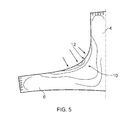
- the surface 12 of the fillet region has got longer not shorter during this shrinkage, the length around the whole joint angle increasing with the reduced radius of curvature. The result of this is that the external surface of the fillet region is under tension, as illustrated in Figure 5 .
- a method of forming a composite component having a fillet joint characterised in that the method comprising thermally insulating the fillet region of the component during cure, such that the fillet region is substantially the last region of the component to cure.
- the method comprising thermally insulating the fillet region of the component during cure, such that the fillet region is substantially the last region of the component to cure.
- An insert may be used which is additionally or alternatively geometrically stable under conditions in which the component is formed.
- the insert may thus provide rigidity to the mould at the fillet region, where deformation of the mould is most damaging to the eventual properties of the component to be formed.
- thermally insulating the fillet region comprises insulating a surface of the fillet from the source of heat that drives the cure process.
- the source of heat may comprises a heated mould an insert may be placed between a surface of the fillet of the component and a surface of a heated mould within which the component is formed.
- the method may further comprise assembling a component fibre preform, introducing the preform into a mould, impregnating the preform with resin, and heating the mould to drive the cure process.
- Reinforcing may comprise inserting an insert into the region of the mould against which the fillet region of the component is formed.
- the method of forming a composite component may also comprise forcing a surface of the fillet region of the component to adopt a non constant radius of curvature while the component is inside the mould during the cure process.
- the non constant radius of curvature may have the effect of lengthening the arc of the component surface at the fillet radius, enabling it to be "stretched out” following component cure, cooling and associated deformation without inducing excessive tensile stresses in the fillet surface.
- Forcing the fillet region to adopt a non constant radius of curvature may comprise forming the fillet region against a forming surface of the mould that has a non constant radius of curvature.
- the method may further comprise releasing the component from the mould and allowing the fillet region to adopt a radius of curvature determined by residual stresses in the component.
- the surface of the fillet region may for example be forced to adopt an elliptical or quartic curve, or some blending of the two.
- the curves may comprise additional small undulations.
- the method may also comprise forming a composite component having a fillet joint that is defined between first and second legs, the method comprising placing the legs of the component in bending during cure of the component. Such bending may assist in control of mould deformation and may also assist in establishing useful residual stress patterns.
- Placing the legs in bending may comprise bending the legs towards each other, such that the angle of the fillet joint is reduced.
- Placing the legs in bending may comprise imparting bending forces to the legs via a mould in which the component is formed.
- the bending forces may be imparted by mechanical actuators, which may for example be built into the mould.
- the bending forces may be imparted by differential thermal expansion of different parts of the mould.
- the differential expansion may be caused by a bimetallic effect.
- a method of forming a composite component having a fillet joint that is defined between first and second legs comprising reducing the thickness of the component at the fillet region, such that the cross section of the component is substantially uniform across the first and second legs and the fillet region of the component.
- a more uniform cross section may achieve reduced component shrinkage and more even resin flow during resin impregnation.
- the reduction in thickness may be achieved by a protrusion on a mould within which the component is formed.
- the reduction in thickness may be achieved by introducing an insert into a mould in which the component is formed.
- the present invention in its various aspects, provides a range of methods and apparatus for the forming of a composite component having a fillet joint.
- Each of the various aspects addresses the poor properties in the fillet region experienced with conventional manufacturing processes and equipment.
- any of the various aspects may be used in combination with any other aspect to beneficial effect.
- a mould of the present invention may comprise an insert having some or all of the properties described, as well as mechanical actuators to place legs of the joint in bending. Many other beneficial combinations of aspects of the invention are possible, as will be appreciated from the following detailed description.
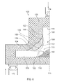
- a mould tooling 102 for a composite "T" joint component 108 comprises a mould body 105 having a mould cavity 116 formed therein.
- the mould tooling 102 is illustrated in part section, showing only one half of the tooling. It will be appreciated that the other half of the mould tooling 102 is a mirror image along the axis 103.
- the mould tooling 102 defines first and second legs 104, 106, of the composite "T" joint component 108 as well as a fillet region 110 between the first and second legs 104, 106.
- the fillet region 110 of the component extends from an arcuate fillet surface 112 to a base 114 of the fillet region 110. It will be appreciated that equivalent component regions are defined in a mould tooling forming an "L" shaped joint also.
- An insert 150 mates with the mould body 105 at the fillet region of the mould tooling 102.
- the insert 150 is formed from a thermally insulating material. The effect of this is to prevent heat energy from the heated mould body 105 from reaching the fillet region 110 of the component via direct conduction. By insulating the fillet region 110 from direct heating by the mould body 105, the insert 150 prevents the early cure and cool of the fillet region that is so damaging to the component in creating tensile stresses at the fillet surface. The insert 150 ensures that the fillet region 110 is substantially the last region of the component 108 to cure, as heat energy to drive the cure process must travel through the rest of the component 108 to reach the fillet region 110.
- the thermal "front” thus approaches the fillet surface 112 of the component 108 from either side and from the direction of the through thickness of the fillet joint itself.
- the fillet region insulated from the applied heat energy, the bulk of the component, and the through thickness of the fillet region cures, and hence shrinks, before the surface area of the fillet region (identified at 122) has hardened.
- the outer region 122 can deform with the shrinkage, without generating stresses within the, as yet uncured, resin of the outer region 122.
- the shrinkage of the through thickness of the fillet region also does not place the through thickness of the fillet region 110 into tension.
- the material of the insert 150 is also highly rigid and is geometrically stable at temperatures and pressures employed during composite component cure. It is an advantage that the thermally insulating materials appropriate for providing the insulating properties of the insert discussed above also tend to have the desired rigidity. Ceramics are an exemplary class of materials displaying the necessary properties.
- the highly rigid insert 150 helps to impart geometrical stability to the mould tooling 102 at the critical fillet region, preventing the bulging effect in the fillet area illustrated in Figure 2 . By preventing this bulging, associated problems with resin flow during impregnation, as well as local pressure changes, can be avoided. This reduces the incidence of local porosity that leads to crack initiation and associated poor strength in this critical region. By managing deformation of the mould tooling 102 in this region, the insert 150 enables lightweight mould tooling to be used in a greater range of high precision applications, avoiding the excessive cost associated with heavier tooling.
- the insert 150 tapers towards first and second edges 152, 154, which may be longitudinal edges extending into and out of the plane of the Figure.
- the ends 152, 154 of the insert thus lie approximately tangentially to the legs of the "T" just beyond the extent of the fillet curvature.
- the tapered edges ensure a smoothly varying applied heat profile over the exposed length of the legs of the joint.
- Non tapered edges to the insert 150 can be envisaged but are less desirable for two reasons. Firstly a step change from insert 150 to mould body 105 would create an abrupt change of temperature gradient which would have an adverse effect on the composite material characteristics in that region. Secondly, the relative thermal expansion of the metal mould body 105 and the insulating insert 150 would be difficult to manage. A gap would likely form, leading to material property issues on the surface of the composite component 108.
- the insert 150 contacts the mould body 105 at a mating interface 156.
- a protrusion 158 is formed on the mating surface of the insert 150 and is received in a corresponding recess in the mating surface of the mould body 105.
- the cooperating protrusion and recess provide a location feature for assembly of the insert 150 in the mould body 105 and also help to prevent slippage of the insert during processing.
- the cooperating protrusion 158 and recess are formed at the very centre of the fillet region of the mould. In this manner, the centre of the fillet, which is the location most at risk from detrimental tensile stress, is provided with additional thermal insulation, and is protected from cure until the very end of the cycle.
- the insert 150 comprises a forming surface 160, against which the fillet of the component 108 is formed.
- the forming surface 160 of the insert 150 traces a curve between the first and second ends 152, 154 of the insert.
- the curve of the forming surface is non circular, the radius of curvature of the curved surface varying across the surface.
- the curved forming surface 160 of the insert 150 traces the following path (from left to right across the fillet): initially, the curve rises a little earlier than a circular arc would rise, the curve then flattens out and passes across the imaginary line of the circular arc, by the halfway mark around the fillet (45° around), the fillet has gone a little deeper into the material than a circular arc would. The rest of the path is a mirror image about the 45° line.
- the curve function need not be symmetrical about the 45° line but it is desirable for the curve to be smooth, in order to avoid step changes and their attendant disadvantages, as discussed above.
- the curve may also include small undulations in additional to the principal curve function.
- a quartic or ellipto-quartic shape would also give a generally greater arc length and so has the property of maintaining a smaller aerodynamic blockage if the "T" joint is to be used at the base of a stator aerofoil attached to a platform in an aero engine.
- thermal insulation at the fillet region, geometric reinforcement and a non circular radius of curvature may each be achieved through a modified mould body.
- the embodiment described represents one exemplary and inventive manner in which these improvements to the established process may be implemented.
- Figure 6 includes a schematic representation of mechanical actuators 172, 174 mounted at the ends of each of the legs of the "T" joint.
- the actuators may be external, such as a loading rig within which the mould tooling 102 may be mounted, or the actuators 172, 174 may be built into the mould tooling 102, attached to upper and lower surfaces in locations chosen for convenience and best effect.
- the effect of the mechanical actuators 172, 174 is to place the legs of the "T" joint into bending during cure.
- the direction of the applied force from the actuators may be either push or pull, or both, and may be applied at particular stages during the cure cycle. Particular alternatives include for example a "4 point bend" type arrangement, such as is used for testing the strength of beams or "T" pieces.
- the loading may be applied across both legs of the joint, urging the legs toward each other.
- Placing the legs of the joint into bending helps to control the deformation of the mould tool 102 during resin inflow, and particularly helps to avoid the bulging effect seen at the fillet region in Figure 2 . This helps to improve resin flow around the fillet region and hence reduce porosity. Placing the legs in bending during cure can also counteract undesirable bending effects caused by the different rates of cure throughout the component, and can be used to establish useful residual stress patterns.
- An alternative embodiment of the invention places the legs of the joint in bending by generating a bimetallic effect in the mould tooling.
- Multiple different metals having differing thermal expansion properties, may be employed within the tooling to cause controlled deformation of the tooling under increased temperature. Such bending is less easy to control directly than the mechanically applied loads, but generally applies a more even stress state. Some control of bending levels can be achieved through local temperature control within the mould tooling.
- the mould tooling 102 further comprises a second insert 180, located substantially at the base of the "T" of the joint.
- the insert 180 may be added to the mould body 105 before the fibre preform is introduced, or the fibre preform may be placed on top of the insert 180.
- the second insert 180 tapers towards opposed edges and comprises a location feature (not shown) to assist placement of the insert 180 and to avoid slippage during cure.
- the insert 180 may be replaced by an integrally formed protrusion on the mould body 105, having the same shape and location as the insert 180.
- the insert 180 ensures the provision of a "T" or "L” joint component 108 having a modified base. This provides a small weight reduction in the component 108 and also reduces stress transmission between the central leg of the "T” and the side legs. This may be particularly useful if the "T" represents a platform mounted stator aerofoil, as this would reduce the vibration stresses through the region and improve fatigue life. More importantly, the reduced composite thickness at the joint region means that thermal and resin shrinkage strains are reduced and have less impact on the embedded residual stresses in the component when it is released from the mould. Additionally, as the preform cross section is much more uniform, the resin injection flow profile is more even, reducing porosity in the fillet region. Finally, the residual stresses in this region can be controlled in a similar way to the fillet area using insulation and thermal gradients.
- the arch of the base, and hence the top arch of the insert 180 should be flat so that the geometry is smooth. If the "T" is asymmetric, the condition of flatness is may not be required, but the importance of smooth geometry remains, as otherwise there would be a propensity for the joint component 108 to split up the centre. In view of the curve imparted to the component surface by the insert 180, it may also be desirable for the insert 180 to be of low thermal conductivity, as discussed in detail with respect to the fillet insert 150.
- FIG. 7 illustrates a more extreme variation of this concept.
- the mould tooling 202 of Figure 7 comprises a mould body 205, cavity 212 and fillet and base inserts 250, 280. Both inserts 250, 280 are thermally insulating.
- the fillet insert 250 of the mould tooling 202 has the effect of extending the fillet of the joint under the base. Such an arrangement would enable the provision for example of a stator vane which is completely un-compromised by fillet region blocking. (The fillet dent may be filled with a lightweight filler material, if necessary).
- the shape of the component 208 formed in the mould tooling 202 is inherently flexible, thus providing good fatigue life.
- the geometry also has the advantage of following the line of the preform without significant thickness variations, which means that it can be created using simple plies without needing a deltoid filler.
- removing the flat base may not be possible, for example where a flat base is a necessary feature.
- the flat base may reinstated after cure of the component by building back the base in filler material after manufacture.
- each of the various aspects of the present invention addresses the issue of poor strength in the critical region of the fillet in composite components having a fillet joint. These poor properties are addressed by:
- T and "L” joints with which the present invention may be beneficially employed can be found in various joints and brackets used for attaching components together.
- "T” shaped joints may for example be found in the design of platform mounted stator aerofoils in an aero engine.
- the present invention may also find application in casing flanges, formed as a solid revolution of an "L" shape. The invention may assist in maintaining flange roundness and controlling swash, as well as managing residual stresses.
Landscapes
- Chemical & Material Sciences (AREA)
- Engineering & Computer Science (AREA)
- Composite Materials (AREA)
- Mechanical Engineering (AREA)
- Physics & Mathematics (AREA)
- Health & Medical Sciences (AREA)
- Oral & Maxillofacial Surgery (AREA)
- Thermal Sciences (AREA)
- Moulding By Coating Moulds (AREA)
- Moulds For Moulding Plastics Or The Like (AREA)
Abstract
Description
- The present invention relates to methods for forming a composite component having a fillet joint, including for example composite components having "T" or "L" joints. The present invention also relates to apparatus in the form of moulds for forming such components.
- Organic matrix composite materials can offer significant advantages over metallic alternatives for component parts of a gas turbine engine, principally in reducing the overall weight of the engine. Many such components include joint regions in the form of a "T" or "L" having a fillet. An exemplary process for forming such components is described below, with reference to
Figures 1 to 5 . -
Figure 1 illustrates one half of alightweight mould tooling 2 for a composite "T" joint. The second half of themould tooling 2 is a mirror image along theaxis 3. Thetooling 2 defines first andsecond legs 4, 6, of the composite "T" joint component 8 as well as afillet region 10 between the first andsecond legs 4, 6. Thefillet region 10 extends from afillet surface 12 to abase 14 of thefillet region 10. It will be appreciated that a further leg (not shown) is defined in the second mirror half of the tooling, and that the first leg 4 forms the stem of the "T", with thesecond leg 6 and final leg (not shown) forming a cross bar of the "T". It will also be appreciated that equivalent component regions are defined in a mould tooling forming an "L" shaped joint, the "L" mould tooling substantially resembling the half of the "T" mould tooling that is illustrated inFigure 1 . As is conventional, thelightweight mould tooling 2 follows the geometric outline of the component to be manufactured. Lightweight tooling is preferred to standard heavier, fully closed tooling, which is of much chunkier form, because it provides cost advantages, particularly in the formation of large components. However, lightweight tooling is subject to deformation under high internal pressures. In practice even the fully closed heavier tooling that is used for high precision parts will deform to a certain degree under very high internal pressures, but the problem is less pronounced than with the lightweight tooling illustrated. - In order to form the composite component 8, the
mould tooling 2 is first disassembled and a fibre preform is introduced into thecavity 16 defined inside it. Themould tooling 2 is then reassembled around the fibre perform. Typically, themould tooling 2 will be formed from several metallic parts that slide or bolt together to provide the finished shape, although this detail is not illustrated on the Figures. - Once the
mould tooling 2 is assembled around the preform, resin is forced into the preform through one or more inlet pipes (not shown) leading through themould tooling 2. One or more outlet pipes (also not shown) provide vacuum pressure to draw the resin through the fibre perform in thecavity 16. Careful choice of positioning of the inlet and outlet pipes ensures that the preform is fully impregnated with resin. Depending on the resin flow pattern within the preform, certain areas may be more susceptible to accumulation of trapped air pockets or other impurities. Choice of input and output positions and pressures can be used to manage this. In some cases, reactive pressure management can be used. Resin at this stage of the process, before cure, is highly viscous and the pressures required within thecavity 16 of themould tooling 2 in order to ensure thorough wetting of the fibre preform are extremely high. At such pressures, thelightweight mould tooling 2 tends to deform, as illustrated inFigure 2 . -
Figure 2 illustrates an exaggerated deformed shape of themould tooling 2 during resin inflow. As thecavity 16 is subject to high pressure, it tends to deform to increase the internal volume, resulting in downward angling of thesecond leg 6 of the joint, indicated byarrow 18, and a pulling forward of the corner of the joint, illustrated atarrow 20. The downward angling of thesecond leg 6 appears severe, but in fact is relatively inconsequential and can be compensated for. The more serious issue is the pulling forward of the corner region, indicated atarrow 20. This change in the corner region increases the radius of curvature of thecavity 16 at the joint, and hence reduces fluid flow rate of the resin around this area, indicated at 22. Any trapped air pockets in this region will tend to stay trapped, and to increase in volume, leading to porosity in the finished component 8 at this critical joint region in the component. In addition, this deformation of themould tooling 2 at the joint corner causes expansion of theadjacent region 22 of the component 8. Such expansion results in reduced pressure at theregion 22, meaning any trapped gas voids will tend to gather in this region rather than being forced out of the component. This too leads to local porosity at this critical region of the joint. - After resin infusion, the composite component is cured under temperature and pressure control. Both temperature and pressure play a role in driving the cure process. The level of control used carries implications both for cost and for the practicalities of the process, but even for the most expensive controlled processes, there will be temperature and pressure variations through the component. This is in part owing to the nature of the composite material. Heat conductivity in the resin itself is low while heat conductivity in the fibres can be low (glass fibre), or moderate (carbon fibres), and depends on the local fibre directionality and proximity to the tooling wall. Heat conductivity in metallic tooling is high. The combination of these different conductivities means that the local temperature inside the component at any given time during the cure cycle will inevitably vary across the component. This variation means that different regions of the component will cure at different rates at different times within the cure processing. After processing, the level of cure in the cured resin will also be different across the component; meaning different regions of the component will have different resin properties.
- Resin cure is an exothermic chemical process, releasing heat as the process progresses, and this heat gives a local rise in temperature in addition to the applied heat. Applied heat is typically achieved by heating the tooling, and thence by heat conduction into the component. Regions which are in close proximity to a metallic wall of tooling with start to heat up first, and will therefore begin to cure first, causing the component to cure from the outside inwards. Temperature and pressure drive the rate of cure and are managed as closely as possible by sensors in the tooling and by applied thermal or pressure gradients in the tooling.
-
Figure 3 illustrates the in-mould deformed shape of the component 8. Thecross-hatched region 24 indicates the areas of the component 8 where the resin cures first, and thedashed line 26 is the "front" of the thermal gradient as the heat penetrates through the component 8. As the outside surface begins to cure before the inside, the outside is relatively rigid compared with the inside. So, when the outside takes on the deformed shape of the mould tool under pressure, the inside is constrained by this. Resin shrinks as it cures; meaning that as the inside cures its shrinkage generally pulls the outside surface, already rigid from having cured first, into compression. However, this propensity holds true only for convex shapes of isotropic material: for composites the differential stiffness and heat conductivity of the fibres will modify this behaviour. Concave regions, such as internal curves in "T" joints can show significantly different residual stress effects, as discussed more fully below. - As the cure progresses, the inside of the composite component begins to heat by exothermic reaction causing its temperature to rise above that of the outside of the component 8. The rising temperature causes expansion (i.e. increased internal pressure), subjecting the mould tooling and already cured outside of the composite to tensile loads. As the resin cures and the
mould tooling 2 eventually cools, there is a double shrinkage effect both from shrinkage caused by cure and shrinkage caused by cooling. - After curing and cooling, the tooling is disassembled and the composite component is released from the mould.
Figure 4 shows typical distortions. The main shrinkage occurs inside the thickest part of the "T" joint. This pulls the fillet radius back inwards, indicated atarrow 28, and theleg 6 of the "T" lifts back up, indicated atarrows 30. The distortion of theleg 6 is easily compensated for by slight modification of themould tooling 2. The most severe issue is the state of internal stress in the fillet region. Surface material being in a residual stress state of compression is generally a positive factor; forcing any cracks or voids to close. Conversely, if the surface stress state is in tension, any cracks or voids are allowed to open or expand and there is a tendency for these to propagate into the bulk of the component material. The inside of the component 8, because it has shrunk, is under tension. The base and the ends of the legs of the "T" are therefore under compression. However, thesurface 12 of the fillet region has got longer not shorter during this shrinkage, the length around the whole joint angle increasing with the reduced radius of curvature. The result of this is that the external surface of the fillet region is under tension, as illustrated inFigure 5 . - As discussed above, tensile stresses on the surface of components are a serious weakness as any surface flaw will act as an initiation site for failure. With the inside region of the component 8 also under tension, any crack that starts in the
fillet 12 will quickly propagate through the thickness of the component 8. Expansion and fluid flow patterns mean thefillet region 10 is a likely collection point for trapped air pockets or other impurities, as discussed more fully above. These voids and impurities form the basis of crack initiation sites, and the end result is that the manufacturing process described above must inevitably generate poor quality "T" joints unless very rigid tooling and process control is used. Even then, poor qualities around the critical fillet region may still be experienced. - It will be noted that the ends of sections of laminate are particularly prone to residual stress state effects which result from the thermal and stiffness conflicts between neighbouring plies. These are illustrated for example by the stress peaks shown at the ends of the
legs 4, 6 of the joint inFigure 5 . These stresses lead to a propensity for component delamination initiating from the ends. In extreme cases, they can lead to the component delaminating spontaneously on release from the mould tooling. To reduce the effect, it is known to match stiffness between plies as carefully as possible (e.g. a 45° ply may be laid on top of a 0° ply, but not a 90° on top of a 0° ply.) - From the foregoing discussion to can be seen that existing manufacturing procedures for composite "T" and "L" joints suffer from excessive cost requirements, even to produce parts that are merely acceptable. Even with the good process control that is achieved at this high cost, the parts are naturally predisposed to have poor properties in the fillet region that is most important to the strength of the entire component. These poor properties arise from porosity in the fillet region and undesirable residual stresses generated in this region during the cure process. Given the problems with manufacture of such components, these parts tend to be over weight in order to achieve the strengths required. If they are part of components such as stator aerofoil to platform joints, then large over generous fillets additionally lead to aerodynamic losses.
- According to the present invention, there is provided a method of forming a composite component having a fillet joint, characterised in that the method comprising thermally insulating the fillet region of the component during cure, such that the fillet region is substantially the last region of the component to cure. In this manner, undesirable tensile residual stresses in the surface area of the fillet region can be significantly reduced.
- An insert may be used which is additionally or alternatively geometrically stable under conditions in which the component is formed. The insert may thus provide rigidity to the mould at the fillet region, where deformation of the mould is most damaging to the eventual properties of the component to be formed.
- Preferably thermally insulating the fillet region comprises insulating a surface of the fillet from the source of heat that drives the cure process.
- The source of heat may comprises a heated mould an insert may be placed between a surface of the fillet of the component and a surface of a heated mould within which the component is formed.
- The method may further comprise assembling a component fibre preform, introducing the preform into a mould, impregnating the preform with resin, and heating the mould to drive the cure process. By physically reinforcing the mould at the fillet region, deformation of the mould at this region is reduced, improving resin flow patterns and reducing local component expansion.
- Reinforcing may comprise inserting an insert into the region of the mould against which the fillet region of the component is formed.
- The method of forming a composite component may also comprise forcing a surface of the fillet region of the component to adopt a non constant radius of curvature while the component is inside the mould during the cure process. The non constant radius of curvature may have the effect of lengthening the arc of the component surface at the fillet radius, enabling it to be "stretched out" following component cure, cooling and associated deformation without inducing excessive tensile stresses in the fillet surface.
- Forcing the fillet region to adopt a non constant radius of curvature may comprise forming the fillet region against a forming surface of the mould that has a non constant radius of curvature.
- The method may further comprise releasing the component from the mould and allowing the fillet region to adopt a radius of curvature determined by residual stresses in the component.
- The surface of the fillet region may for example be forced to adopt an elliptical or quartic curve, or some blending of the two. The curves may comprise additional small undulations.
- The method may also comprise forming a composite component having a fillet joint that is defined between first and second legs, the method comprising placing the legs of the component in bending during cure of the component. Such bending may assist in control of mould deformation and may also assist in establishing useful residual stress patterns.
- Placing the legs in bending may comprise bending the legs towards each other, such that the angle of the fillet joint is reduced.
- Placing the legs in bending may comprise imparting bending forces to the legs via a mould in which the component is formed.
- The bending forces may be imparted by mechanical actuators, which may for example be built into the mould.
- The bending forces may be imparted by differential thermal expansion of different parts of the mould. The differential expansion may be caused by a bimetallic effect.
- There may also be provided a method of forming a composite component having a fillet joint that is defined between first and second legs, the method comprising reducing the thickness of the component at the fillet region, such that the cross section of the component is substantially uniform across the first and second legs and the fillet region of the component. A more uniform cross section may achieve reduced component shrinkage and more even resin flow during resin impregnation.
- The reduction in thickness may be achieved by a protrusion on a mould within which the component is formed. The reduction in thickness may be achieved by introducing an insert into a mould in which the component is formed.
- The present invention, in its various aspects, provides a range of methods and apparatus for the forming of a composite component having a fillet joint. Each of the various aspects addresses the poor properties in the fillet region experienced with conventional manufacturing processes and equipment. It will be appreciated that any of the various aspects may be used in combination with any other aspect to beneficial effect. For example, a mould of the present invention may comprise an insert having some or all of the properties described, as well as mechanical actuators to place legs of the joint in bending. Many other beneficial combinations of aspects of the invention are possible, as will be appreciated from the following detailed description.
- For a better understanding of the present invention, and to show more clearly how it may be carried into effect, reference will now be made, by way of example, to the following drawings, in which:-
-
Figure 1 is a part sectional illustration of a light weight mould tooling for a composite "T" joint. -
Figure 2 is an illustration of the mould ofFigure 1 illustrating exaggerated typical deformation during resin impregnation. -
Figure 3 is a representation of a component formed within the mould ofFigure 1 , illustrating deformation of the component in the mould. -
Figure 4 illustrates typical distortion of a component on release from the mould ofFigure 1 . -
Figure 5 is a representative illustration showing the residual stress state inside a component on release form the mould ofFigure 1 . -
Figure 6 is an illustration of a mould embodying aspects of the present invention. -
Figure 7 is an illustration of another mould embodying aspects of the present invention. - As discussed above, the various aspects of the present invention, both method and apparatus, may be employed singly or in combination to beneficial effect. The following detailed description discloses two exemplary embodiments of mould tooling, each of which embody some combination of the inventive aspects disclosed above. It will be appreciated that alternative combinations of inventive aspects may be considered. Particularly as regards the methods of forming components disclosed and claimed in the present specification, it will be appreciated that the moulds described in detail below represent merely one exemplary manner in which the methods may practically be employed.
- With reference to
Figure 6 , amould tooling 102 for a composite "T"joint component 108 comprises amould body 105 having amould cavity 116 formed therein. Themould tooling 102 is illustrated in part section, showing only one half of the tooling. It will be appreciated that the other half of themould tooling 102 is a mirror image along theaxis 103. Themould tooling 102 defines first andsecond legs joint component 108 as well as afillet region 110 between the first andsecond legs fillet region 110 of the component extends from anarcuate fillet surface 112 to abase 114 of thefillet region 110. It will be appreciated that equivalent component regions are defined in a mould tooling forming an "L" shaped joint also. Aninsert 150 mates with themould body 105 at the fillet region of themould tooling 102. - The
insert 150 is formed from a thermally insulating material. The effect of this is to prevent heat energy from theheated mould body 105 from reaching thefillet region 110 of the component via direct conduction. By insulating thefillet region 110 from direct heating by themould body 105, theinsert 150 prevents the early cure and cool of the fillet region that is so damaging to the component in creating tensile stresses at the fillet surface. Theinsert 150 ensures that thefillet region 110 is substantially the last region of thecomponent 108 to cure, as heat energy to drive the cure process must travel through the rest of thecomponent 108 to reach thefillet region 110. The thermal "front" thus approaches thefillet surface 112 of thecomponent 108 from either side and from the direction of the through thickness of the fillet joint itself. With the fillet region insulated from the applied heat energy, the bulk of the component, and the through thickness of the fillet region cures, and hence shrinks, before the surface area of the fillet region (identified at 122) has hardened. Thus, as the through thickness of the fillet region shrinks on cure, theouter region 122 can deform with the shrinkage, without generating stresses within the, as yet uncured, resin of theouter region 122. As the through thickness is not constrained by a hardened outer region, the shrinkage of the through thickness of the fillet region also does not place the through thickness of thefillet region 110 into tension. By the time the resin in thecritical surface area 122 is curing, the remainder of the component has substantially cured and thus only thermal shrinkage effects will be experienced in this region post cure. The result of this thermal insulation, and the consequent change in order in which the component regions cure, is that the final residual stresses in theentire fillet region 110, including thesurface region 122, are those due to the spring-back of the rest of the component on release from the mould. These stresses are easier to predict and manage, and other tooling design manipulations can ensure that the resulting residual stress state in the fillet area is compressive (i.e. beneficial in suppressing fatigue crack propagation at the fillet area). - The material of the
insert 150 is also highly rigid and is geometrically stable at temperatures and pressures employed during composite component cure. It is an advantage that the thermally insulating materials appropriate for providing the insulating properties of the insert discussed above also tend to have the desired rigidity. Ceramics are an exemplary class of materials displaying the necessary properties. The highlyrigid insert 150 helps to impart geometrical stability to themould tooling 102 at the critical fillet region, preventing the bulging effect in the fillet area illustrated inFigure 2 . By preventing this bulging, associated problems with resin flow during impregnation, as well as local pressure changes, can be avoided. This reduces the incidence of local porosity that leads to crack initiation and associated poor strength in this critical region. By managing deformation of themould tooling 102 in this region, theinsert 150 enables lightweight mould tooling to be used in a greater range of high precision applications, avoiding the excessive cost associated with heavier tooling. - The
insert 150, viewed in cross section as inFigure 6 , tapers towards first andsecond edges insert 150 can be envisaged but are less desirable for two reasons. Firstly a step change frominsert 150 tomould body 105 would create an abrupt change of temperature gradient which would have an adverse effect on the composite material characteristics in that region. Secondly, the relative thermal expansion of themetal mould body 105 and the insulatinginsert 150 would be difficult to manage. A gap would likely form, leading to material property issues on the surface of thecomposite component 108. - The
insert 150 contacts themould body 105 at amating interface 156. Aprotrusion 158 is formed on the mating surface of theinsert 150 and is received in a corresponding recess in the mating surface of themould body 105. The cooperating protrusion and recess provide a location feature for assembly of theinsert 150 in themould body 105 and also help to prevent slippage of the insert during processing. The cooperatingprotrusion 158 and recess are formed at the very centre of the fillet region of the mould. In this manner, the centre of the fillet, which is the location most at risk from detrimental tensile stress, is provided with additional thermal insulation, and is protected from cure until the very end of the cycle. - The
insert 150 comprises a formingsurface 160, against which the fillet of thecomponent 108 is formed. The formingsurface 160 of theinsert 150 traces a curve between the first and second ends 152, 154 of the insert. The curve of the forming surface is non circular, the radius of curvature of the curved surface varying across the surface. In the embodiment ofFigure 6 , the curved formingsurface 160 of theinsert 150 traces the following path (from left to right across the fillet): initially, the curve rises a little earlier than a circular arc would rise, the curve then flattens out and passes across the imaginary line of the circular arc, by the halfway mark around the fillet (45° around), the fillet has gone a little deeper into the material than a circular arc would. The rest of the path is a mirror image about the 45° line. - It will be appreciated that the curve illustrated in
Figure 6 and described above is merely an example. The curve may follow an elliptical path: (x/a)2 + (y/b)2 = 1, a quartic path e.g. X4 + y4 = R4, or (x/c)4 + (y/d)4 = 1 , or various combinations of these (e.g. [(x/a)2 + (y/b)2 - 1 ] * [(x/c)4 + (y/d)4 - 1 ] ... * [(x/p)2n + (y/q)2n - 1] = 0. - The curve function need not be symmetrical about the 45° line but it is desirable for the curve to be smooth, in order to avoid step changes and their attendant disadvantages, as discussed above. The curve may also include small undulations in additional to the principal curve function.
- By varying the geometry of the forming
surface 160 of theinsert 150, and hence of the fillet surface on the component, fine control of the fillet arc length, and thus the levels of residual stress in the fillet, can be achieved. Undulations and other variations from a pure circular arc give rise to a slightly longer fillet arc length than would be provided were the radius of curvature constant and the arc a perfect circular arc. These undulations can be stretched out to form a circular arc that extends around the reduced radius of curvature after the component is released from the mould. Thus the inevitable lengthening of the arc that follows spring back of the joint legs, and the attendant reduction in joint angle, can be accommodated merely by smoothing out the undulations without inducing tensile stresses in the surface material. A quartic or ellipto-quartic shape would also give a generally greater arc length and so has the property of maintaining a smaller aerodynamic blockage if the "T" joint is to be used at the base of a stator aerofoil attached to a platform in an aero engine. - It will be appreciated that many of the advantages provided by the
insert 150 of the present embodiment may be achieved through alternative means. For example, thermal insulation at the fillet region, geometric reinforcement and a non circular radius of curvature may each be achieved through a modified mould body. The embodiment described represents one exemplary and inventive manner in which these improvements to the established process may be implemented. -
Figure 6 includes a schematic representation ofmechanical actuators mould tooling 102 may be mounted, or theactuators mould tooling 102, attached to upper and lower surfaces in locations chosen for convenience and best effect. The effect of themechanical actuators - Placing the legs of the joint into bending helps to control the deformation of the
mould tool 102 during resin inflow, and particularly helps to avoid the bulging effect seen at the fillet region inFigure 2 . This helps to improve resin flow around the fillet region and hence reduce porosity. Placing the legs in bending during cure can also counteract undesirable bending effects caused by the different rates of cure throughout the component, and can be used to establish useful residual stress patterns. - An alternative embodiment of the invention (not shown) places the legs of the joint in bending by generating a bimetallic effect in the mould tooling. Multiple different metals, having differing thermal expansion properties, may be employed within the tooling to cause controlled deformation of the tooling under increased temperature. Such bending is less easy to control directly than the mechanically applied loads, but generally applies a more even stress state. Some control of bending levels can be achieved through local temperature control within the mould tooling.
- With reference again to
Figure 6 , themould tooling 102 further comprises asecond insert 180, located substantially at the base of the "T" of the joint. Theinsert 180 may be added to themould body 105 before the fibre preform is introduced, or the fibre preform may be placed on top of theinsert 180. As with the previously describedfillet insert 150, thesecond insert 180 tapers towards opposed edges and comprises a location feature (not shown) to assist placement of theinsert 180 and to avoid slippage during cure. Alternatively, theinsert 180 may be replaced by an integrally formed protrusion on themould body 105, having the same shape and location as theinsert 180. - The
insert 180 ensures the provision of a "T" or "L"joint component 108 having a modified base. This provides a small weight reduction in thecomponent 108 and also reduces stress transmission between the central leg of the "T" and the side legs. This may be particularly useful if the "T" represents a platform mounted stator aerofoil, as this would reduce the vibration stresses through the region and improve fatigue life. More importantly, the reduced composite thickness at the joint region means that thermal and resin shrinkage strains are reduced and have less impact on the embedded residual stresses in the component when it is released from the mould. Additionally, as the preform cross section is much more uniform, the resin injection flow profile is more even, reducing porosity in the fillet region. Finally, the residual stresses in this region can be controlled in a similar way to the fillet area using insulation and thermal gradients. - In the case of a symmetric "T" joint, the arch of the base, and hence the top arch of the
insert 180, should be flat so that the geometry is smooth. If the "T" is asymmetric, the condition of flatness is may not be required, but the importance of smooth geometry remains, as otherwise there would be a propensity for thejoint component 108 to split up the centre. In view of the curve imparted to the component surface by theinsert 180, it may also be desirable for theinsert 180 to be of low thermal conductivity, as discussed in detail with respect to thefillet insert 150. -
Figure 7 illustrates a more extreme variation of this concept. Themould tooling 202 ofFigure 7 comprises amould body 205, cavity 212 and fillet and base inserts 250, 280. Both inserts 250, 280 are thermally insulating. Thefillet insert 250 of themould tooling 202 has the effect of extending the fillet of the joint under the base. Such an arrangement would enable the provision for example of a stator vane which is completely un-compromised by fillet region blocking. (The fillet dent may be filled with a lightweight filler material, if necessary). The shape of the component 208 formed in themould tooling 202 is inherently flexible, thus providing good fatigue life. The geometry also has the advantage of following the line of the preform without significant thickness variations, which means that it can be created using simple plies without needing a deltoid filler. - In some cases, removing the flat base may not be possible, for example where a flat base is a necessary feature. In such cases the flat base may reinstated after cure of the component by building back the base in filler material after manufacture.
- As previously discussed, some or all of the concepts described above may be used in combination. Alone or in combination, each of the various aspects of the present invention addresses the issue of poor strength in the critical region of the fillet in composite components having a fillet joint. These poor properties are addressed by:
- 1) Reducing porosity in the critical load region of the fillet area though improving resin flow paths and reducing pressure changes in the critical region during cure; and/or
- 2) Suppressing harmful residual stresses, which may include replacing those harmful residual stresses with beneficial ones.
- "T" and "L" joints with which the present invention may be beneficially employed can be found in various joints and brackets used for attaching components together. "T" shaped joints may for example be found in the design of platform mounted stator aerofoils in an aero engine. The present invention may also find application in casing flanges, formed as a solid revolution of an "L" shape. The invention may assist in maintaining flange roundness and controlling swash, as well as managing residual stresses.
- Aspects of the invention may be defined by the following lettered clauses:
- A A mould for a composite component having a fillet joint, the mould comprising a mould body having a cavity within which the component is formed, and an insert mating with the mould body and comprising a forming surface against which, in use, the fillet of the component fillet joint is formed.
- B A mould as in lettered clause A, wherein the insert is thermally insulating.
- C A mould as in lettered clause A or B, wherein the insert is geometrically stable under conditions in which the component is formed.
- D A mould as in any one of the preceding lettered clauses, wherein the forming surface of the insert describes a curve between first and second longitudinal edges, the curve having a radius of curvature that is non constant.
- E A mould as in lettered clause D, wherein the curve comprises undulations.
- G A mould as in any one of the preceding lettered clauses, wherein the insert tapers towards first and second longitudinal edges.
- H A mould as in any one of the preceding lettered clauses, wherein a mating interface between the insert and the mould body comprises a locating feature.
- I A mould as in lettered clause H, wherein the locating feature comprises a protrusion and cooperating recess.
- J A mould as in lettered clause I, wherein the protrusion is formed on the insert and cooperating recess is formed on the mould body. The protrusion may protrude from the surface of the insert at a location which, in use, is substantially opposite the centre of the fillet joint of the component.
- K A mould as in any one of the preceding lettered clauses, wherein the mould comprises mechanical actuators, operable to place opposed legs of the fillet joint in bending.
- L A mould as in any one of the preceding lettered clauses, wherein the mould is formed from at least two substances having different thermal expansion properties.
- M A mould as in lettered clause L, wherein one of the substances is metalic.
- N A mould as in lettered clause L or lettered clause M, wherein one of the substances is ceramic.
- O A mould as in any one of the preceding lettered clauses, wherein the cavity defined by the mould and insert is of substantially uniform cross section across opposed legs of the fillet joint and the fillet region of the fillet joint
- P A mould as in lettered clause 0, wherein the substantially uniform cross section at the fillet region is defined between the insert against which the fillet of the component is formed, and a second insert, against which in use, the base of the fillet joint is formed.
- Q A method of forming a composite component having a fillet joint, the method comprising thermally insulating the fillet region of the component during cure, such that the fillet region is substantially the last region of the component to cure.
- R A method as in lettered clause Q, wherein thermally insulating the fillet region comprises insulating a surface of the fillet from the source of heat that drives the cure process.
- S A method as in lettered clause R, wherein the source of heat comprises a heated mould.
- T A method as in any one of lettered clauses Q to S, wherein the method further comprises assembling a component fibre preform, introducing the preform into a mould, impregnating the preform with resin, and heating the mould to drive the cure process.
- U A method as in any one of lettered clauses Q to T, wherein thermally insulating the fillet region comprises placing an insert between a surface of the fillet of the component and a surface of a heated mould within which the component is formed.
- V A method as in any one of lettered clauses S to U, further comprising reinforcing the mould at the fillet region.
- W A method as in lettered clause V, wherein reinforcing the mould at the fillet region comprises placing an insert in the mould at the fillet region.
- X A method of forming a composite component having a fillet joint using a mould, the method comprising physically reinforcing the mould at the fillet region of the component.
- Y A method as in lettered clause X, wherein reinforcing comprises inserting an insert into the region of the mould against which the fillet region of the component is formed.
- Z A method of forming a composite component having a fillet joint using a mould, the method comprising forcing a surface of the fillet region of the component to adopt a non constant radius of curvature while the component is inside the mould during the cure process.
- AA A method as in lettered clause Z, wherein forcing the fillet region to adopt a non constant radius of curvature comprises forming the fillet region against a forming surface of the mould that has a non constant radius of curvature.
- AB A method as in lettered clause Z or AA, further comprising releasing the component from the mould and allowing the fillet region to adopt a radius of curvature determined by residual stresses in the component.
- AC A method of forming a composite component having a fillet joint that is defined between first and second legs, the method comprising placing the legs of the component in bending during cure of the component.
- AD A method as in lettered clause AC, wherein placing the legs in bending comprises bending the legs towards each other, such that the angle of the fillet joint is reduced.
- AE A method as in lettered clause AC or AD, wherein placing the legs in bending comprises imparting bending forces to the legs via a mould in which the component is formed.
- AF A method as in lettered clause AE, wherein the bending forces are imparted by mechanical actuators.
- AG A method as in lettered clause AF, wherein the mechanical actuators are built into the mould.
- AH A method as in lettered clause AE, wherein the bending forces are imparted by differential thermal expansion of different parts of the mould.
- Al A method as in lettered clause AH, wherein the differential expansion is caused by a bimetallic effect.
- AJ A mould for a composite component having a fillet joint that is defined between first and second legs, the mould comprising a mould body having a cavity within which the component is formed, and means for placing the legs of the component in bending during cure of the component.
- AK A mould as in lettered clause AJ, wherein the means for placing the legs in bending comprises mechanical actuators.
- AL A mould as in lettered clause AJ or AK, wherein the mould body is formed from at least two metals having different thermal expansion properties.
- AM A method of forming a composite component having a fillet joint that is defined between first and second legs, the method comprising reducing the thickness of the component at the fillet region, such that the cross section of the component is substantially uniform across the first and second legs and the fillet region of the component.
- AN A method as in lettered clause AM, wherein the reduction in thickness is achieved by a protrusion on a mould within which the component is formed.
- AO A method as in lettered clause AM, wherein the reduction in thickness is achieved by introducing an insert into a mould in which the component is formed.
- AP A mould for a composite component having a fillet joint that is defined between first and second legs, the mould comprising a mould body defining a cavity within which the component is formed wherein the cavity is of substantially uniform cross section across the legs of the fillet joint and the fillet region of the fillet joint.
- AQ A mould as in lettered clause AP, further comprising a protrusion at the region where the base of the fillet joint is formed.
- AR A mould as in lettered clause AQ, wherein the protrusion comprises an insert.
- AS A mould as in lettered clause AR, wherein the insert tapers towards opposed edges.
Claims (15)
- A method of forming a composite component having a fillet joint (8), characterised in that the method comprises thermally insulating the fillet region of the component during cure, such that the fillet region is substantially the last region of the component to cure.
- A method as claimed in claim 1, wherein thermally insulating the fillet region comprises insulating a surface of the fillet from the source of heat that drives the cure process.
- A method as claimed in claim 2, wherein the source of heat comprises a heated mould (105).
- A method as claimed in any one of claims 1 to 3, wherein the method further comprises assembling a component fibre preform, introducing the preform into a mould (105), impregnating the preform with resin, and heating the mould to drive the cure process.
- A method as claimed in any one of claims 1 to 4, wherein thermally insulating the fillet region comprises placing an insert between a surface of the fillet of the component and a surface of a heated mould within which the component is formed.
- A method as claimed in any one of claims 3 to 5, further comprising reinforcing the mould at the fillet region.
- A method as claimed in claim 6, wherein reinforcing the mould at the fillet region comprises placing an insert in the mould at the fillet region against which the fillet region of the component is formed.
- A method as claimed in any one of claims 1 to 7, the method further comprising forcing a surface of the fillet region of the component to adopt a non constant radius of curvature while the component is inside the mould during the cure process.
- A method as claimed in claim 8, wherein forcing the fillet region to adopt a non constant radius of curvature comprises forming the fillet region against a forming surface of the mould that has a non constant radius of curvature.
- A method as claimed in claim 8 or 9, further comprising releasing the component from the mould and allowing the fillet region to adopt a radius of curvature determined by residual stresses in the component.
- A method according to claim 4, wherein the method further comprises forming the composite component between first (152) and second (154) legs, the method comprising placing the legs of the component in bending during cure of the component.
- A method as claimed in claim 11, wherein placing the legs in bending comprises bending the legs towards each other, such that the angle of the fillet joint is reduced.
- A method as claimed in claim 11 or 12, wherein placing the legs in bending comprises imparting bending forces to the legs via a mould in which the component is formed, the bending forces being imparted by either mechanical actuators or by thermal expansion of different parts of the mould.
- A method according to any preceding claim, the method further comprising reducing the thickness of the component at the fillet region, such that the cross section of the component is substantially uniform across the first and second legs and the fillet region of the component.
- A method as claimed in claim 14, wherein the reduction in thickness is achieved by either a protrusion on a mould within which the component is formed or by introducing an insert into a mould in which the component is formed.
Applications Claiming Priority (1)
| Application Number | Priority Date | Filing Date | Title |
|---|---|---|---|
| GBGB1016869.8A GB201016869D0 (en) | 2010-10-07 | 2010-10-07 | Methods and apparatus for forming a composite component |
Publications (3)
| Publication Number | Publication Date |
|---|---|
| EP2439060A2 true EP2439060A2 (en) | 2012-04-11 |
| EP2439060A3 EP2439060A3 (en) | 2017-07-05 |
| EP2439060B1 EP2439060B1 (en) | 2018-05-30 |
Family
ID=43243640
Family Applications (1)
| Application Number | Title | Priority Date | Filing Date |
|---|---|---|---|
| EP11178582.0A Not-in-force EP2439060B1 (en) | 2010-10-07 | 2011-08-24 | Methods and apparatus for forming a composite component |
Country Status (3)
| Country | Link |
|---|---|
| US (1) | US8703033B2 (en) |
| EP (1) | EP2439060B1 (en) |
| GB (1) | GB201016869D0 (en) |
Cited By (4)
| Publication number | Priority date | Publication date | Assignee | Title |
|---|---|---|---|---|
| WO2014058561A1 (en) * | 2012-10-10 | 2014-04-17 | The Boeing Company | Shape-distorting tooling system and method for curing composite parts |
| CN105150562A (en) * | 2015-10-20 | 2015-12-16 | 南京航空航天大学 | Pull-extrusion device with function of molding rib at stepped type curing degree and working method of pull-extrusion device |
| FR3045449A1 (en) * | 2015-12-21 | 2017-06-23 | Deutsches Zentrum Fur Luft- Und Raumfahrt E V | |
| CN112476882A (en) * | 2020-11-16 | 2021-03-12 | 青岛泰思科机电工程有限公司 | V-belt vulcanization method |
Families Citing this family (3)
| Publication number | Priority date | Publication date | Assignee | Title |
|---|---|---|---|---|
| US10132170B2 (en) | 2013-03-15 | 2018-11-20 | General Electric Company | Systems and method for a composite blade with fillet transition |
| ES2626352T3 (en) * | 2013-05-30 | 2017-07-24 | Airbus Operations S.L. | Hybrid tool to cure composite parts |
| CN112454760B (en) * | 2020-09-22 | 2022-05-10 | 成都飞机工业(集团)有限责任公司 | Mold surface deformation compensation mold repairing method for composite material member mold |
Family Cites Families (5)
| Publication number | Priority date | Publication date | Assignee | Title |
|---|---|---|---|---|
| US5229141A (en) * | 1990-12-21 | 1993-07-20 | Mozer Rudolph W | Carbon fiber facsimile process |
| US5817269A (en) * | 1996-10-25 | 1998-10-06 | The Boeing Company | Composite fabrication method and tooling to improve part consolidation |
| US20020125613A1 (en) * | 2001-03-08 | 2002-09-12 | Cominsky Kenneth D. | Mandrel fabrication for cobond assembly |
| JP4444248B2 (en) * | 2006-08-08 | 2010-03-31 | 三菱重工業株式会社 | RTM molding apparatus and RTM molded body manufacturing method |
| US8834668B2 (en) * | 2008-11-19 | 2014-09-16 | The Boeing Company | Staged cocuring of composite structures |
-
2010
- 2010-10-07 GB GBGB1016869.8A patent/GB201016869D0/en not_active Ceased
-
2011
- 2011-08-24 EP EP11178582.0A patent/EP2439060B1/en not_active Not-in-force
- 2011-08-24 US US13/216,713 patent/US8703033B2/en active Active
Non-Patent Citations (1)
| Title |
|---|
| None |
Cited By (9)
| Publication number | Priority date | Publication date | Assignee | Title |
|---|---|---|---|---|
| WO2014058561A1 (en) * | 2012-10-10 | 2014-04-17 | The Boeing Company | Shape-distorting tooling system and method for curing composite parts |
| US8986484B2 (en) | 2012-10-10 | 2015-03-24 | The Boeing Company | Shape-distorting tooling system and method for curing composite parts |
| CN104718058A (en) * | 2012-10-10 | 2015-06-17 | 波音公司 | Shape-distorting tooling system and method for curing composite parts |
| US9610711B2 (en) | 2012-10-10 | 2017-04-04 | The Boeing Company | Shape-distorting tooling system for curing composite parts |
| CN104718058B (en) * | 2012-10-10 | 2017-12-19 | 波音公司 | For solidifying the shape distortion tool system and method for composite part |
| CN105150562A (en) * | 2015-10-20 | 2015-12-16 | 南京航空航天大学 | Pull-extrusion device with function of molding rib at stepped type curing degree and working method of pull-extrusion device |
| FR3045449A1 (en) * | 2015-12-21 | 2017-06-23 | Deutsches Zentrum Fur Luft- Und Raumfahrt E V | |
| CN112476882A (en) * | 2020-11-16 | 2021-03-12 | 青岛泰思科机电工程有限公司 | V-belt vulcanization method |
| CN112476882B (en) * | 2020-11-16 | 2022-03-15 | 青岛泰思科机电工程有限公司 | V-belt vulcanization method |
Also Published As
| Publication number | Publication date |
|---|---|
| EP2439060A3 (en) | 2017-07-05 |
| US20120086152A1 (en) | 2012-04-12 |
| US8703033B2 (en) | 2014-04-22 |
| EP2439060B1 (en) | 2018-05-30 |
| GB201016869D0 (en) | 2010-11-17 |
Similar Documents
| Publication | Publication Date | Title |
|---|---|---|
| EP2439060B1 (en) | Methods and apparatus for forming a composite component | |
| JP5424891B2 (en) | Apparatus and method for forming a hat-reinforced composite part using a thermal expansion tooling call | |
| EP2004390B1 (en) | Method of producing stiffened panels made of a composite | |
| CN103974819B (en) | The high-pressure molding of composite material component | |
| CA2419444C (en) | Apparatus and method for joining dissimilar materials to form a structural support member | |
| CN100594110C (en) | Apparatus for the manufacture of reinforced composite materials | |
| CN103180123B (en) | Method and system for forming one-piece composite parts with shape memory polymer devices | |
| KR102022130B1 (en) | Lightweight flexible mandrel and method for making the same | |
| US8007628B2 (en) | Cellular composite grid-stiffened structure | |
| US20070128043A1 (en) | Cmc component and method of fabrication | |
| CN111936303A (en) | Method of manufacturing a blade with an assembled metal leading edge for a gas turbine engine from a composite material | |
| EP1938953A1 (en) | Methods for fabricating composite structures with flanges having tethered corners | |
| US20100239427A1 (en) | Method of manufacturing a component comprising an internal structure | |
| JP2011516295A (en) | Method for tolerance compensation between two fiber composite components | |
| US6290889B1 (en) | Process for producing precision hollow articles made of composite material | |
| CN110104202B (en) | Composite aircraft manufacturing tool using articulated mandrels | |
| US7527757B2 (en) | Method of producing polyimide matrix composite parts | |
| CN107530988B (en) | Method and apparatus for forming composite parts | |
| US20150202800A1 (en) | Method for manufacturing a molding tool intended for molding a part made of composite material | |
| JP6769995B2 (en) | How to make composite parts and preforms | |
| EP2484653A2 (en) | Fiber-reinforced article and method of it's making | |
| CN112092415B (en) | Method for producing a composite component | |
| CN102770573B (en) | Method for making a composite metal part having inner reinforcements in the form of fibers, blank for implementing same and metal part thus obtained | |
| CN119458963A (en) | Method for producing a component from a fiber composite material | |
| CN107530989B (en) | Tools for forming composite parts |
Legal Events
| Date | Code | Title | Description |
|---|---|---|---|
| AK | Designated contracting states |
Kind code of ref document: A2 Designated state(s): AL AT BE BG CH CY CZ DE DK EE ES FI FR GB GR HR HU IE IS IT LI LT LU LV MC MK MT NL NO PL PT RO RS SE SI SK SM TR |
|
| AX | Request for extension of the european patent |
Extension state: BA ME |
|
| PUAI | Public reference made under article 153(3) epc to a published international application that has entered the european phase |
Free format text: ORIGINAL CODE: 0009012 |
|
| RAP1 | Party data changed (applicant data changed or rights of an application transferred) |
Owner name: ROLLS-ROYCE PLC |
|
| PUAL | Search report despatched |
Free format text: ORIGINAL CODE: 0009013 |
|
| AK | Designated contracting states |
Kind code of ref document: A3 Designated state(s): AL AT BE BG CH CY CZ DE DK EE ES FI FR GB GR HR HU IE IS IT LI LT LU LV MC MK MT NL NO PL PT RO RS SE SI SK SM TR |
|
| AX | Request for extension of the european patent |
Extension state: BA ME |
|
| RIC1 | Information provided on ipc code assigned before grant |
Ipc: B29C 35/02 20060101ALI20170531BHEP Ipc: B29C 70/48 20060101AFI20170531BHEP Ipc: B29C 70/54 20060101ALI20170531BHEP Ipc: B29C 35/00 20060101ALI20170531BHEP |
|
| STAA | Information on the status of an ep patent application or granted ep patent |
Free format text: STATUS: REQUEST FOR EXAMINATION WAS MADE |
|
| 17P | Request for examination filed |
Effective date: 20180103 |
|
| RBV | Designated contracting states (corrected) |
Designated state(s): AL AT BE BG CH CY CZ DE DK EE ES FI FR GB GR HR HU IE IS IT LI LT LU LV MC MK MT NL NO PL PT RO RS SE SI SK SM TR |
|
| GRAP | Despatch of communication of intention to grant a patent |
Free format text: ORIGINAL CODE: EPIDOSNIGR1 |
|
| STAA | Information on the status of an ep patent application or granted ep patent |
Free format text: STATUS: GRANT OF PATENT IS INTENDED |
|
| INTG | Intention to grant announced |
Effective date: 20180321 |
|
| GRAS | Grant fee paid |
Free format text: ORIGINAL CODE: EPIDOSNIGR3 |
|
| GRAA | (expected) grant |
Free format text: ORIGINAL CODE: 0009210 |
|
| STAA | Information on the status of an ep patent application or granted ep patent |
Free format text: STATUS: THE PATENT HAS BEEN GRANTED |
|
| AK | Designated contracting states |
Kind code of ref document: B1 Designated state(s): AL AT BE BG CH CY CZ DE DK EE ES FI FR GB GR HR HU IE IS IT LI LT LU LV MC MK MT NL NO PL PT RO RS SE SI SK SM TR |
|
| REG | Reference to a national code |
Ref country code: GB Ref legal event code: FG4D |
|
| REG | Reference to a national code |
Ref country code: CH Ref legal event code: EP |
|
| REG | Reference to a national code |
Ref country code: AT Ref legal event code: REF Ref document number: 1003177 Country of ref document: AT Kind code of ref document: T Effective date: 20180615 |
|
| REG | Reference to a national code |
Ref country code: IE Ref legal event code: FG4D |
|
| REG | Reference to a national code |
Ref country code: DE Ref legal event code: R096 Ref document number: 602011048725 Country of ref document: DE |
|
| REG | Reference to a national code |
Ref country code: FR Ref legal event code: PLFP Year of fee payment: 8 |
|
| REG | Reference to a national code |
Ref country code: NL Ref legal event code: MP Effective date: 20180530 |
|
| REG | Reference to a national code |
Ref country code: LT Ref legal event code: MG4D |
|
| PG25 | Lapsed in a contracting state [announced via postgrant information from national office to epo] |
Ref country code: SE Free format text: LAPSE BECAUSE OF FAILURE TO SUBMIT A TRANSLATION OF THE DESCRIPTION OR TO PAY THE FEE WITHIN THE PRESCRIBED TIME-LIMIT Effective date: 20180530 Ref country code: FI Free format text: LAPSE BECAUSE OF FAILURE TO SUBMIT A TRANSLATION OF THE DESCRIPTION OR TO PAY THE FEE WITHIN THE PRESCRIBED TIME-LIMIT Effective date: 20180530 Ref country code: BG Free format text: LAPSE BECAUSE OF FAILURE TO SUBMIT A TRANSLATION OF THE DESCRIPTION OR TO PAY THE FEE WITHIN THE PRESCRIBED TIME-LIMIT Effective date: 20180830 Ref country code: CY Free format text: LAPSE BECAUSE OF FAILURE TO SUBMIT A TRANSLATION OF THE DESCRIPTION OR TO PAY THE FEE WITHIN THE PRESCRIBED TIME-LIMIT Effective date: 20180530 Ref country code: NO Free format text: LAPSE BECAUSE OF FAILURE TO SUBMIT A TRANSLATION OF THE DESCRIPTION OR TO PAY THE FEE WITHIN THE PRESCRIBED TIME-LIMIT Effective date: 20180830 Ref country code: ES Free format text: LAPSE BECAUSE OF FAILURE TO SUBMIT A TRANSLATION OF THE DESCRIPTION OR TO PAY THE FEE WITHIN THE PRESCRIBED TIME-LIMIT Effective date: 20180530 Ref country code: LT Free format text: LAPSE BECAUSE OF FAILURE TO SUBMIT A TRANSLATION OF THE DESCRIPTION OR TO PAY THE FEE WITHIN THE PRESCRIBED TIME-LIMIT Effective date: 20180530 |
|
| PG25 | Lapsed in a contracting state [announced via postgrant information from national office to epo] |
Ref country code: GR Free format text: LAPSE BECAUSE OF FAILURE TO SUBMIT A TRANSLATION OF THE DESCRIPTION OR TO PAY THE FEE WITHIN THE PRESCRIBED TIME-LIMIT Effective date: 20180831 Ref country code: HR Free format text: LAPSE BECAUSE OF FAILURE TO SUBMIT A TRANSLATION OF THE DESCRIPTION OR TO PAY THE FEE WITHIN THE PRESCRIBED TIME-LIMIT Effective date: 20180530 Ref country code: LV Free format text: LAPSE BECAUSE OF FAILURE TO SUBMIT A TRANSLATION OF THE DESCRIPTION OR TO PAY THE FEE WITHIN THE PRESCRIBED TIME-LIMIT Effective date: 20180530 Ref country code: RS Free format text: LAPSE BECAUSE OF FAILURE TO SUBMIT A TRANSLATION OF THE DESCRIPTION OR TO PAY THE FEE WITHIN THE PRESCRIBED TIME-LIMIT Effective date: 20180530 |
|
| REG | Reference to a national code |
Ref country code: AT Ref legal event code: MK05 Ref document number: 1003177 Country of ref document: AT Kind code of ref document: T Effective date: 20180530 |
|
| PG25 | Lapsed in a contracting state [announced via postgrant information from national office to epo] |
Ref country code: NL Free format text: LAPSE BECAUSE OF FAILURE TO SUBMIT A TRANSLATION OF THE DESCRIPTION OR TO PAY THE FEE WITHIN THE PRESCRIBED TIME-LIMIT Effective date: 20180530 |
|
| PG25 | Lapsed in a contracting state [announced via postgrant information from national office to epo] |
Ref country code: CZ Free format text: LAPSE BECAUSE OF FAILURE TO SUBMIT A TRANSLATION OF THE DESCRIPTION OR TO PAY THE FEE WITHIN THE PRESCRIBED TIME-LIMIT Effective date: 20180530 Ref country code: RO Free format text: LAPSE BECAUSE OF FAILURE TO SUBMIT A TRANSLATION OF THE DESCRIPTION OR TO PAY THE FEE WITHIN THE PRESCRIBED TIME-LIMIT Effective date: 20180530 Ref country code: DK Free format text: LAPSE BECAUSE OF FAILURE TO SUBMIT A TRANSLATION OF THE DESCRIPTION OR TO PAY THE FEE WITHIN THE PRESCRIBED TIME-LIMIT Effective date: 20180530 Ref country code: AT Free format text: LAPSE BECAUSE OF FAILURE TO SUBMIT A TRANSLATION OF THE DESCRIPTION OR TO PAY THE FEE WITHIN THE PRESCRIBED TIME-LIMIT Effective date: 20180530 Ref country code: EE Free format text: LAPSE BECAUSE OF FAILURE TO SUBMIT A TRANSLATION OF THE DESCRIPTION OR TO PAY THE FEE WITHIN THE PRESCRIBED TIME-LIMIT Effective date: 20180530 Ref country code: PL Free format text: LAPSE BECAUSE OF FAILURE TO SUBMIT A TRANSLATION OF THE DESCRIPTION OR TO PAY THE FEE WITHIN THE PRESCRIBED TIME-LIMIT Effective date: 20180530 Ref country code: SK Free format text: LAPSE BECAUSE OF FAILURE TO SUBMIT A TRANSLATION OF THE DESCRIPTION OR TO PAY THE FEE WITHIN THE PRESCRIBED TIME-LIMIT Effective date: 20180530 |
|
| PG25 | Lapsed in a contracting state [announced via postgrant information from national office to epo] |
Ref country code: IT Free format text: LAPSE BECAUSE OF FAILURE TO SUBMIT A TRANSLATION OF THE DESCRIPTION OR TO PAY THE FEE WITHIN THE PRESCRIBED TIME-LIMIT Effective date: 20180530 Ref country code: SM Free format text: LAPSE BECAUSE OF FAILURE TO SUBMIT A TRANSLATION OF THE DESCRIPTION OR TO PAY THE FEE WITHIN THE PRESCRIBED TIME-LIMIT Effective date: 20180530 |
|
| REG | Reference to a national code |
Ref country code: DE Ref legal event code: R097 Ref document number: 602011048725 Country of ref document: DE |
|
| PG25 | Lapsed in a contracting state [announced via postgrant information from national office to epo] |
Ref country code: MC Free format text: LAPSE BECAUSE OF FAILURE TO SUBMIT A TRANSLATION OF THE DESCRIPTION OR TO PAY THE FEE WITHIN THE PRESCRIBED TIME-LIMIT Effective date: 20180530 |
|
| REG | Reference to a national code |
Ref country code: CH Ref legal event code: PL |
|
| PLBE | No opposition filed within time limit |
Free format text: ORIGINAL CODE: 0009261 |
|
| STAA | Information on the status of an ep patent application or granted ep patent |
Free format text: STATUS: NO OPPOSITION FILED WITHIN TIME LIMIT |
|
| PG25 | Lapsed in a contracting state [announced via postgrant information from national office to epo] |
Ref country code: LI Free format text: LAPSE BECAUSE OF NON-PAYMENT OF DUE FEES Effective date: 20180831 Ref country code: LU Free format text: LAPSE BECAUSE OF NON-PAYMENT OF DUE FEES Effective date: 20180824 Ref country code: CH Free format text: LAPSE BECAUSE OF NON-PAYMENT OF DUE FEES Effective date: 20180831 |
|
| 26N | No opposition filed |
Effective date: 20190301 |
|
| REG | Reference to a national code |
Ref country code: BE Ref legal event code: MM Effective date: 20180831 |
|
| PG25 | Lapsed in a contracting state [announced via postgrant information from national office to epo] |
Ref country code: SI Free format text: LAPSE BECAUSE OF FAILURE TO SUBMIT A TRANSLATION OF THE DESCRIPTION OR TO PAY THE FEE WITHIN THE PRESCRIBED TIME-LIMIT Effective date: 20180530 |
|
| PG25 | Lapsed in a contracting state [announced via postgrant information from national office to epo] |
Ref country code: BE Free format text: LAPSE BECAUSE OF NON-PAYMENT OF DUE FEES Effective date: 20180831 |
|
| PG25 | Lapsed in a contracting state [announced via postgrant information from national office to epo] |
Ref country code: AL Free format text: LAPSE BECAUSE OF FAILURE TO SUBMIT A TRANSLATION OF THE DESCRIPTION OR TO PAY THE FEE WITHIN THE PRESCRIBED TIME-LIMIT Effective date: 20180530 |
|
| PG25 | Lapsed in a contracting state [announced via postgrant information from national office to epo] |
Ref country code: MT Free format text: LAPSE BECAUSE OF NON-PAYMENT OF DUE FEES Effective date: 20180824 |
|
| PG25 | Lapsed in a contracting state [announced via postgrant information from national office to epo] |
Ref country code: TR Free format text: LAPSE BECAUSE OF FAILURE TO SUBMIT A TRANSLATION OF THE DESCRIPTION OR TO PAY THE FEE WITHIN THE PRESCRIBED TIME-LIMIT Effective date: 20180530 |
|
| PG25 | Lapsed in a contracting state [announced via postgrant information from national office to epo] |
Ref country code: HU Free format text: LAPSE BECAUSE OF FAILURE TO SUBMIT A TRANSLATION OF THE DESCRIPTION OR TO PAY THE FEE WITHIN THE PRESCRIBED TIME-LIMIT; INVALID AB INITIO Effective date: 20110824 Ref country code: PT Free format text: LAPSE BECAUSE OF FAILURE TO SUBMIT A TRANSLATION OF THE DESCRIPTION OR TO PAY THE FEE WITHIN THE PRESCRIBED TIME-LIMIT Effective date: 20180530 |
|
| PG25 | Lapsed in a contracting state [announced via postgrant information from national office to epo] |
Ref country code: IE Free format text: LAPSE BECAUSE OF NON-PAYMENT OF DUE FEES Effective date: 20180824 Ref country code: MK Free format text: LAPSE BECAUSE OF NON-PAYMENT OF DUE FEES Effective date: 20180530 |
|
| PG25 | Lapsed in a contracting state [announced via postgrant information from national office to epo] |
Ref country code: IS Free format text: LAPSE BECAUSE OF FAILURE TO SUBMIT A TRANSLATION OF THE DESCRIPTION OR TO PAY THE FEE WITHIN THE PRESCRIBED TIME-LIMIT Effective date: 20180930 |
|
| P01 | Opt-out of the competence of the unified patent court (upc) registered |
Effective date: 20230528 |
|
| PGFP | Annual fee paid to national office [announced via postgrant information from national office to epo] |
Ref country code: GB Payment date: 20230822 Year of fee payment: 13 |
|
| PGFP | Annual fee paid to national office [announced via postgrant information from national office to epo] |
Ref country code: FR Payment date: 20230824 Year of fee payment: 13 Ref country code: DE Payment date: 20230828 Year of fee payment: 13 |
|
| REG | Reference to a national code |
Ref country code: DE Ref legal event code: R119 Ref document number: 602011048725 Country of ref document: DE |
|
| GBPC | Gb: european patent ceased through non-payment of renewal fee |
Effective date: 20240824 |
|
| PG25 | Lapsed in a contracting state [announced via postgrant information from national office to epo] |
Ref country code: DE Free format text: LAPSE BECAUSE OF NON-PAYMENT OF DUE FEES Effective date: 20250301 |
|
| PG25 | Lapsed in a contracting state [announced via postgrant information from national office to epo] |
Ref country code: GB Free format text: LAPSE BECAUSE OF NON-PAYMENT OF DUE FEES Effective date: 20240824 |
|
| PG25 | Lapsed in a contracting state [announced via postgrant information from national office to epo] |
Ref country code: FR Free format text: LAPSE BECAUSE OF NON-PAYMENT OF DUE FEES Effective date: 20240831 |