EP2439023A1 - Electric tool - Google Patents
Electric tool Download PDFInfo
- Publication number
- EP2439023A1 EP2439023A1 EP10783208A EP10783208A EP2439023A1 EP 2439023 A1 EP2439023 A1 EP 2439023A1 EP 10783208 A EP10783208 A EP 10783208A EP 10783208 A EP10783208 A EP 10783208A EP 2439023 A1 EP2439023 A1 EP 2439023A1
- Authority
- EP
- European Patent Office
- Prior art keywords
- bearing
- motor
- support member
- electric power
- bearing support
- Prior art date
- Legal status (The legal status is an assumption and is not a legal conclusion. Google has not performed a legal analysis and makes no representation as to the accuracy of the status listed.)
- Withdrawn
Links
- XEEYBQQBJWHFJM-UHFFFAOYSA-N Iron Chemical group [Fe] XEEYBQQBJWHFJM-UHFFFAOYSA-N 0.000 claims description 9
- 230000004323 axial length Effects 0.000 claims description 6
- 239000012212 insulator Substances 0.000 claims description 5
- 230000007423 decrease Effects 0.000 abstract description 10
- 238000003780 insertion Methods 0.000 description 5
- 230000037431 insertion Effects 0.000 description 5
- 239000000758 substrate Substances 0.000 description 3
- 230000003247 decreasing effect Effects 0.000 description 2
- 238000001816 cooling Methods 0.000 description 1
- 230000004048 modification Effects 0.000 description 1
- 238000012986 modification Methods 0.000 description 1
Images




Classifications
-
- B—PERFORMING OPERATIONS; TRANSPORTING
- B25—HAND TOOLS; PORTABLE POWER-DRIVEN TOOLS; MANIPULATORS
- B25F—COMBINATION OR MULTI-PURPOSE TOOLS NOT OTHERWISE PROVIDED FOR; DETAILS OR COMPONENTS OF PORTABLE POWER-DRIVEN TOOLS NOT PARTICULARLY RELATED TO THE OPERATIONS PERFORMED AND NOT OTHERWISE PROVIDED FOR
- B25F5/00—Details or components of portable power-driven tools not particularly related to the operations performed and not otherwise provided for
- B25F5/02—Construction of casings, bodies or handles
Definitions
- the present invention relates to an electric power tool configured such that a motor used as a drive source is housed in a dual-separated type housing of the electric power tool.
- Patent Document 1 An existing electric power tool relating to the present invention is disclosed in Patent Document 1.
- the electric power tool disclosed in Patent Document 1 is an impact driver and includes a dual-separated type housing, as shown in Fig. 5 .
- the housing includes a substantially cylindrical housing body and a grip configured to protrude downward from the housing body.
- a motor used as a drive source of the impact driver is housed at the rear portion of the housing body.
- the motor includes a stator 105 and a rotator 107, and a rotary shaft 108 of the rotator 107 is supported by a front bearing 109f and a rear bearing 109b.
- a disk-shaped fan 106 is fixed on the rotary shaft 108 between the rotator 107 and the rear bearing 109b.
- the rear bearing 109b is configured to be supported from outside in the radial direction by a receiving portion (not shown) of the dual-separated housing.
- Patent Document 1 Japanese Laid-Open Patent Publication No. 2007-295773
- the rear bearing 109b is configured to be supported from outside in the radial direction by the receiving portion of the dual-separated type housing. Therefore, in order to support the rear bearing 109b entirely by means of the receiving portion of the housing, it is necessary that the outer circumferential surface of the rear bearing 109b protrude completely from the fan 106. Accordingly, the length of the electric power tool increases by an amount equal to that of the rear bearing 109b protruded. Further, in order to decrease the length of the electric power tool as much as possible, it may be possible to dispose a part of the rear bearing 109b inside the fan 106.
- the present invention has been made to solve the above problem and it is an object of the present invention to decrease the entire length of an electric power tool by preventing a decrease in support strength of a bearing, even if a part of the bearing of a motor is disposed inside a component (for example, a fan) of the electric power tool that includes a dual-separated type housing.
- the invention of claim 1 provides an electric power tool configured such that a motor used as a drive source is housed in a dual-separated type housing and includes a bearing support member that covers the outer circumferential surface of a bearing of the motor and supports the bearing from outside in the radial direction, in which the bearing and one end of the bearing support member in the axial direction are at least partially inserted in a tool component that is coaxially disposed, and a protruding portion that is the other end of the bearing support member which axially protrudes from the tool component is supported by receiving portions of a pair of housing parts.
- the bearing and one end of the bearing support member of the motor in the axial direction are at least partially inserted in the tool component that is coaxially disposed. That is, the bearing of the motor and the tool component partially and axially (in the horizontal direction of the tool) overlaps with each other. Therefore, as compared with the configuration of the related art in which the bearing of the motor protrudes completely from the tool component and is supported by the receiving portions of parts of the left and right housing, it is possible to decrease the length of the electric power tool by an amount equal to the overlapping area of the bearing of the motor and the tool component. Further, the bearing of the motor is supported from outside in the radial direction by the bearing support member, with the outer circumferential surface of the bearing entirely covered by the bearing support member.
- the protruding part of the bearing support member that protrudes axially from the tool component is configured to be supported from outside in the radial direction by the receiving portions of the pair of the housing parts. As described above, since the bearing is supported entirely by the bearing support member even though the bearing of the motor and the tool component partially overlap each other, support strength of the bearing of the motor is not decreased.
- the axial length of the protruding part of the bearing support member is smaller than that of the bearing of the motor. That is, it is possible to decrease the length of the electric power tool in comparison to the related art by an amount equal to the difference between the length of the protruding portion of the bearing support member and the length of the bearing of the motor.
- a baffle for the housing is formed at the protruding part of the bearing support member. Therefore, it is possible to prevent rotation of the bearing support member with respect to the housing.
- the tool component is a fan fixed on a rotary shaft of the motor, a fixing iron core of the motor, or an insulator covering teeth of the fixing iron core.
- the invention of claim 5 provides an electric power tool configured such that a motor used as a drive source is housed in a dual-separated type housing and includes a bearing support member that covers the outer circumferential surface of a bearing of the motor and supports the bearing from outside in the radial direction, in which the bearing support member is disposed between a fan fixed on a rotary shaft of the motor and a fixing iron core of the motor, and the outer circumferential edge of the bearing support member is supported by receiving portions of a pair of housing parts.
- the bearing support member has an opening at the center portion thereof and brings a wind, which is generated by the fan when the motor rotates, into the center. That is, the bearing support member can be configured by a baffle plate that brings a wind generated by the fan into the center, and it is not necessary to provide a separate member that only serves to support the bearing of the motor.
- the electric power tool according to a first embodiment of the present invention is described hereafter with reference to Figs. 1 to 5 .
- the electric power tool according to the embodiment is an impact driver (hereafter, referred to as an electric power tool) including a DC brushless motor (hereafter, referred to as a motor) as a drive source.
- the front, rear, left, right, up, and down directions in the figures correspond to the front, rear, left, right, up, and down directions of the electric power tool.
- the housing 11 of an electric power tool 10 is a dual-separated type housing, and the housing 11 can be assembled by combining a left housing part L with a right housing part R.
- the housing 11 includes a cylindrical housing body 12 that houses a motor 20 and a grip portion 15 protruding from a side (the lower portion in Fig. 5 ) of the housing body 12.
- the grip portion 15 is a portion that a user holds to use the electric power tool 10 and includes a holding portion 16 and a battery-retaining portion 17 positioned at the protruding end (lower end) of the holding portion 16.
- the holding portion 16 is relatively small in diameter to be easily held by the user, and a trigger-type main switch 18 is located at the base end of the holding portion 16.
- the battery-retaining portion 17 extends horizontally (mainly forward) with respect to the holding portion 16 and a battery (not shown) is connected to the lower side of the battery-retaining portion 17.
- the motor 20 used as a drive source of the electric power tool 10 is housed at the rear portion of the housing body 12, and a driving mechanism (not shown) that receives a rotational force of the motor 20 and rotates a front tool (not shown) is houses at the front portion.
- the motor 20 includes a rotator 22 having a permanent magnet, a stator 23 having a fixing iron core and a driving coil (not shown), a sensor substrate 32 having a magnetic sensor that detects a position of the magnetic pole of the rotator 22, and a motor cooling fan 25.
- the sensor substrate 32 is formed in the form of a circular plate and coaxially located on the front surface side of the stator 23 (right end side in Fig.
- a hole 32h through which a rotary shaft 22j of the rotator 22 is placed is formed at the center of the sensor substrate 32.
- the fan 25 is coaxially fixed on the rotary shaft 22j of the rotator 22 at the rear of the rotator 22 (left end side in Fig. 1 ) to integrally rotate with the rotary shaft 22j.
- the rear end 22b of the rotary shaft 22j that protrudes to rearward of the fan 25 is supported by a rear bearing 41.
- a front end 22f of the rotary shaft 22j of the rotator 22 is supported by a front bearing 43.
- the front bearing 43 is supported from outside in the radial direction by a central cylindrical portion 45e of a front bearing support member 45 that is formed in the form of a circular plate and separates the inside of the housing body 12 in a horizontal direction.
- the rear bearing 41 is supported from outside in the radial direction by a rear bearing support member 47.
- the rear bearing support member 47 includes a circular plate portion 472 and a cylindrical portion 474 coaxially formed on the front surface of the circular plate portion 472.
- the circular plate portion 472 of the rear bearing support member 47 is fixed to the housing body 12 and has a through-hole 472h at the center portion through which the rear end of the rotary shaft 22j of the rotator 22 is inserted.
- protrusions 472s that protrude outward in the radial direction are formed on the outer circumferential surface of the circular plate portion 472 facing each other across the center portion, and the protrusions 472s prevents the rear bearing support member 47 from rotating with respect to the housing body 12.
- the cylindrical portion 474 of the rear bearing support member 47 is a portion for housing the rear bearing 41, and the inner diameter of the cylindrical portion 474 is sized to press-fit the rear bearing 41.
- the outer diameter of the cylindrical portion 474 is sized such that the cylindrical portion 474 can be axially inserted in a circular recession 25h formed at the center of the rear surface of the fan 25, as shown in Fig. 1 .
- a predetermined clearance is provided between the outer circumferential surface of the cylindrical portion 474 of the rear bearing support member 47 and the inner circumferential surface of the circular recession 25h of the fan 25 such that the fan 25 can rotate with respect to the cylindrical portion 474, as shown in Fig. 4B .
- the axial length of the cylindrical portion 474 of the rear bearing support member 47 is sized to be substantially the same as that of the rear bearing 41. Therefore, the rear bearing 41 can be inserted entirely in the cylindrical portion 474 of the rear bearing support member 47. That is, the cylindrical portion 474 of the rear bearing support member 47 covers the entire surface of the outer circumferential surface of the rear bearing 41. Further, as shown in Fig. 4B , the depth of the circular recession 25h of the fan 25 in the axial direction is sized such that about 80% or more of each of the cylindrical portion 474 of the rear bearing support member 47 and the rear bearing 41 can be inserted.
- the protrusion length T of the rear bearing support member 47 that protrudes rearward from the fan 25 is sized to be sufficiently smaller than the axial lengths J of the rear bearing 41 and the cylindrical portion 474.
- the protruding portion of the rear bearing support member 47 which protrudes rearward from the fan 25, that is, part of the circular plate portion 472 and the cylindrical portion 474 are held and supported from the right and left side by receiving portions 12u formed at the left housing part L and the right housing part R.
- the rear bearing 41 corresponds to a bearing of the present invention and the rear bearing support member 47 corresponds to a bearing support member of the present invention.
- the circular plate portion 472 of the rear bearing support member 47 corresponds to a protrusion of the present invention and the fan 25 corresponds to a tool component of the present invention.
- the rear bearing 41 and one end (front end) of the rear bearing support member 47 of the motor 20 in the axial direction are at least partially inserted in the circular recession 25h of the fan 15 disposed coaxially. That is, the rear bearing 41 of the motor 20 and the fan 25 partially and axially (longitudinally) overlap with each other. Therefore, as compared with the configuration of the prior art in which the rear bearing 41 of the motor 20 protrudes from the fan 25 completely and the rear bearing 41 is supported by the receiving portions 12u of the left and right housing parts L and R, it is possible to decrease the length of the electric power tool 10 by an amount substantially equal to the overlapping area of the rear bearing 41 and the fan 25.
- the axial length T that equals to the length of the circular plate portion 472 added by the length of a part of the cylindrical portion 474 of the rear bearing support member 47 that protrudes from the fan 25 in the axial direction is sized to be sufficiently smaller than the axis length J of the rear bearing 41.
- the rear bearing 41 of the motor 20 is supported from outside in the radial direction by the rear bearing support member 47, with the outer circumferential surface of the rear bearing 41 completely covered by the rear bearing support member 47.
- the protruding portion (circular plate portion 472) of the rear bearing support member 47 that protrudes rearward from the fan 25 is configured to be supported from outside in the radial direction by the receiving portions 12u of the pair of housing parts L and R.
- the rear bearing 41 of the motor 20 partially overlaps the fan 25, the rear bearing 41 is entirely supported by the rear bearing support member 47, so that the support strength of the rear bearing 41 of the motor 20 is not reduced. Further, since the protrusion 472s is formed in the circular plate portion 472 of the rear bearing support member 47, it is possible to prevent the rear bearing support member 47 from rotating with respect to the housing 11.
- An electric power tool according to a second embodiment of the present invention is described hereafter with reference to Figs. 6 to 8 .
- An electric power tool according to the second embodiment can be obtained by modifying the supporting structure of the rear bearing 41 of the electric power tool 10 in the first embodiment, and the other configurations are the same as those of the electric power tool 10 in the first embodiment. Therefore, the same members as those of the electric power tool 10 in the first embodiment are given the same reference numerals and the explanation about those numbers is not provided.
- a rear bearing 41 is mounted at the center portion of a baffle plate 50 in the form of a circular plate, as shown in Figs. 6 and 7 .
- the baffle plate 50 is for bring a wind generated by a fan 25 to the center of a motor 20 and is positioned between a stator 23 and the fan 25.
- the baffle plate 50 includes a cylindrical portion 52 provided at a center portion, a plurality of frame portions 54 (six in case of Fig. 7 ) radially formed on the outer circumferential surface of the cylindrical portion 52, and a ring-shaped flat plate portion 56 circumferentially connecting the outward ends (outer circumferential ends) of the frame portions 54.
- a plurality of substantially fan-shaped openings 55 (six in case of Fig. 7 ) is formed around the cylindrical portion 52 of the baffle plate 50, by the outer circumferential surface of the cylindrical portion 52, the pair of frame portions 54, and the inner circumferential surface of the ring-shaped flat plate portion 56.
- a wind from the fan 25 passes through the openings 55 and is brought to the center of the motor 20.
- a bearing press-fitting hole 52j where the rear baring 41 is press-fitted is formed at the front portion of the cylindrical portion 52 of the baffle plate 50 and a ring insertion hole 52r where a fan-fixing ring 25k is inserted is formed at the rear portion of the cylindrical portion 52.
- the bearing press-fitting hole 52j and the ring insertion hole 52r of the cylindrical portion 52 are coaxially formed, and the bearing press-fitting hole 52j is configured to be larger than the ring insertion hole 52r in diameter.
- a ring-shaped step 52d is formed between the bearing press-fitting hole 52j and the ring insertion hole 52r.
- the rear bearing 41 is press-fitted in the bearing press-fitting hole 52j of the cylindrical portion 52 to come in contact with the step 52d.
- the axial length of the bearing press-fitting hole 52j of the cylindrical portion 52 is sized to be the same as that of the rear bearing 41. Therefore, the rear bearing 41 can be housed completely in the bearing press-fitting hole 52j of the cylindrical portion 52.
- the fan-fixing ring 25k is inserted in the ring insertion hole 52r of the cylindrical portion 52 of the baffle plate 50 such that the fan-fixing ring 25k rotates relatively with respect to the baffle plate 50.
- the fan-fixing ring 25k is fixed on a rotary shaft 22j to rotate integrally with the rotary shaft 22j of the motor 20. Further, the fan 25 is mounted to the fan-fixing ring 25k to rotate integrally with the rotary shaft 22j. Further, as shown in Fig.
- an upper cut plane 56u and a lower cut plane 56d for preventing the baffle plate 50 from rotating with respect to the housing body 12 are formed on the upper surface and the lower surface of the outer circumferential surface of the ring-shaped flat plate portion 56 of the baffle plate 50.
- the outer circumferential surface of the baffle plate 50 is held and supported from the right and left side by the receiving portions 12u formed at a left housing part L and a right housing part R of the housing 11.
- a part of an insulator 23q which covers the teeth (not shown) of a fixing iron core of the stator 23, axially (horizontally) and partially overlaps the cylindrical portion 52 of the baffle plate 50 and the rear bearing 41, as shown in Fig. 6 and 8 .
- the baffle plate 50 corresponds to the bearing support member of the present invention
- the insulator 23q and the fixing iron core correspond to the tool components of the present invention.
- the bearing support member can be obtained by using the baffle plate 50 that brings the wind generated by the fan 25 to the center of the motor 20, it is not necessary to provide a separate member only for supporting the bearing of the motor 20. Therefore, it is possible both to reduce the cost and to decrease the axial (horizontal) length of the motor 20.
- the present invention is not limited to the embodiments described above and may be modified without departing from the scope of the present invention.
- the first and second embodiments exemplify that the present invention is applied to the rear bearing 41 and the rear bearing support member 47. However, for example, the present invention may be applied to the front bearing 43 and the front bearing support member 45.
- the first and second embodiments exemplify that the DC brushless motor 20 is used in the electric power tool 10 as a drive source.
- the present invention may be applied to an electric power tool including a general DC motor or AC motor, which has a brush, as a drive source.
Landscapes
- Engineering & Computer Science (AREA)
- Mechanical Engineering (AREA)
- Portable Power Tools In General (AREA)
- Motor Or Generator Frames (AREA)
- Drilling And Boring (AREA)
- Connection Of Motors, Electrical Generators, Mechanical Devices, And The Like (AREA)
Abstract
Description
- The present invention relates to an electric power tool configured such that a motor used as a drive source is housed in a dual-separated type housing of the electric power tool.
- An existing electric power tool relating to the present invention is disclosed in Patent Document 1.
The electric power tool disclosed in Patent Document 1 is an impact driver and includes a dual-separated type housing, as shown inFig. 5 .
The housing includes a substantially cylindrical housing body and a grip configured to protrude downward from the housing body. Further, a motor used as a drive source of the impact driver is housed at the rear portion of the housing body. As shown inFig. 9 , the motor includes astator 105 and arotator 107, and arotary shaft 108 of therotator 107 is supported by a front bearing 109f and a rear bearing 109b. Further, a disk-shaped fan 106 is fixed on therotary shaft 108 between therotator 107 and the rear bearing 109b. The rear bearing 109b is configured to be supported from outside in the radial direction by a receiving portion (not shown) of the dual-separated housing. - Patent Document 1: Japanese Laid-Open Patent Publication No.
2007-295773 - In the electric power tool described above, the rear bearing 109b is configured to be supported from outside in the radial direction by the receiving portion of the dual-separated type housing. Therefore, in order to support the rear bearing 109b entirely by means of the receiving portion of the housing, it is necessary that the outer circumferential surface of the rear bearing 109b protrude completely from the
fan 106. Accordingly, the length of the electric power tool increases by an amount equal to that of the rear bearing 109b protruded.
Further, in order to decrease the length of the electric power tool as much as possible, it may be possible to dispose a part of the rear bearing 109b inside thefan 106. However, in this configuration, since only the remaining part of the rear bearing 109b that protrudes rearward from thefan 106 can be used to support by means of the receiving portion of the housing, there is a problem in that support strength of the rear bearing 109b decreases.
Further, the problem is solved when the housing is formed in a cylindrical shape, but the handle portion becomes a separate part and the number of parts of the housing increases, which results in an increase of the cost. - The present invention has been made to solve the above problem and it is an object of the present invention to decrease the entire length of an electric power tool by preventing a decrease in support strength of a bearing, even if a part of the bearing of a motor is disposed inside a component (for example, a fan) of the electric power tool that includes a dual-separated type housing.
- The above problem can be solved by the inventions as defined in the appended claims.
The invention of claim 1 provides an electric power tool configured such that a motor used as a drive source is housed in a dual-separated type housing and includes a bearing support member that covers the outer circumferential surface of a bearing of the motor and supports the bearing from outside in the radial direction, in which the bearing and one end of the bearing support member in the axial direction are at least partially inserted in a tool component that is coaxially disposed, and a protruding portion that is the other end of the bearing support member which axially protrudes from the tool component is supported by receiving portions of a pair of housing parts. - According to the present invention, the bearing and one end of the bearing support member of the motor in the axial direction are at least partially inserted in the tool component that is coaxially disposed. That is, the bearing of the motor and the tool component partially and axially (in the horizontal direction of the tool) overlaps with each other. Therefore, as compared with the configuration of the related art in which the bearing of the motor protrudes completely from the tool component and is supported by the receiving portions of parts of the left and right housing, it is possible to decrease the length of the electric power tool by an amount equal to the overlapping area of the bearing of the motor and the tool component.
Further, the bearing of the motor is supported from outside in the radial direction by the bearing support member, with the outer circumferential surface of the bearing entirely covered by the bearing support member. Further, the protruding part of the bearing support member that protrudes axially from the tool component is configured to be supported from outside in the radial direction by the receiving portions of the pair of the housing parts. As described above, since the bearing is supported entirely by the bearing support member even though the bearing of the motor and the tool component partially overlap each other, support strength of the bearing of the motor is not decreased. - According to the invention of claim 2, the axial length of the protruding part of the bearing support member is smaller than that of the bearing of the motor.
That is, it is possible to decrease the length of the electric power tool in comparison to the related art by an amount equal to the difference between the length of the protruding portion of the bearing support member and the length of the bearing of the motor. - According to the invention of claim 3, a baffle for the housing is formed at the protruding part of the bearing support member.
Therefore, it is possible to prevent rotation of the bearing support member with respect to the housing.
According to the invention of claim 4, the tool component is a fan fixed on a rotary shaft of the motor, a fixing iron core of the motor, or an insulator covering teeth of the fixing iron core. - The invention of claim 5 provides an electric power tool configured such that a motor used as a drive source is housed in a dual-separated type housing and includes a bearing support member that covers the outer circumferential surface of a bearing of the motor and supports the bearing from outside in the radial direction, in which the bearing support member is disposed between a fan fixed on a rotary shaft of the motor and a fixing iron core of the motor, and the outer circumferential edge of the bearing support member is supported by receiving portions of a pair of housing parts.
- According to the invention of claim 6, the bearing support member has an opening at the center portion thereof and brings a wind, which is generated by the fan when the motor rotates, into the center.
That is, the bearing support member can be configured by a baffle plate that brings a wind generated by the fan into the center, and it is not necessary to provide a separate member that only serves to support the bearing of the motor. - According to the present invention, it is possible to decrease the entire length of the electric power tool as much as possible without decreasing the support strength of the bearing of the motor.
-
-
Fig. 1 is a vertical cross-sectional view of a motor of an electric power tool according to a first embodiment of the present invention. -
Fig. 2 is a perspective view of the motor of the electric power tool. -
Figs. 3A and 3B are perspective views of a rear bearing support member used in the electric power tool. -
Fig. 4A is a vertical cross-sectional view of a housing body of the electric power tool andFig. 4B is an enlarged view of a portion B inFig. 4A . -
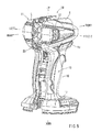
Fig. 5 is a rear perspective view showing the housing of the electric power tool. -
Fig. 6 is a vertical cross-sectional view of a motor of an electric power tool according to a second embodiment of the present invention. -
Figs. 7A and 7B are perspective views of a baffle plate used in the electric power tool. -
Fig. 8 is a vertical cross-sectional view of the housing body of the electric power tool. -
Fig. 9 is a vertical cross-sectional view of a motor of an electric power tool of a prior art. - An electric power tool according to a first embodiment of the present invention is described hereafter with reference to
Figs. 1 to 5 . The electric power tool according to the embodiment is an impact driver (hereafter, referred to as an electric power tool) including a DC brushless motor (hereafter, referred to as a motor) as a drive source.
The front, rear, left, right, up, and down directions in the figures correspond to the front, rear, left, right, up, and down directions of the electric power tool. - As shown in
Fig. 5 , thehousing 11 of anelectric power tool 10 according to the embodiment is a dual-separated type housing, and thehousing 11 can be assembled by combining a left housing part L with a right housing part R.
Thehousing 11 includes acylindrical housing body 12 that houses amotor 20 and agrip portion 15 protruding from a side (the lower portion inFig. 5 ) of thehousing body 12.
Thegrip portion 15 is a portion that a user holds to use theelectric power tool 10 and includes aholding portion 16 and a battery-retainingportion 17 positioned at the protruding end (lower end) of theholding portion 16. Theholding portion 16 is relatively small in diameter to be easily held by the user, and a trigger-typemain switch 18 is located at the base end of theholding portion 16. The battery-retainingportion 17 extends horizontally (mainly forward) with respect to theholding portion 16 and a battery (not shown) is connected to the lower side of the battery-retainingportion 17. - In the
housing body 12, themotor 20 used as a drive source of theelectric power tool 10 is housed at the rear portion of thehousing body 12, and a driving mechanism (not shown) that receives a rotational force of themotor 20 and rotates a front tool (not shown) is houses at the front portion.
As shown inFigs. 1 and 2 , themotor 20 includes arotator 22 having a permanent magnet, astator 23 having a fixing iron core and a driving coil (not shown), asensor substrate 32 having a magnetic sensor that detects a position of the magnetic pole of therotator 22, and amotor cooling fan 25.
Thesensor substrate 32 is formed in the form of a circular plate and coaxially located on the front surface side of the stator 23 (right end side inFig. 1 ). Further, ahole 32h through which arotary shaft 22j of therotator 22 is placed is formed at the center of thesensor substrate 32.
Thefan 25 is coaxially fixed on therotary shaft 22j of therotator 22 at the rear of the rotator 22 (left end side inFig. 1 ) to integrally rotate with therotary shaft 22j. Further, therear end 22b of therotary shaft 22j that protrudes to rearward of thefan 25 is supported by arear bearing 41. Further, afront end 22f of therotary shaft 22j of therotator 22 is supported by afront bearing 43. - The
front bearing 43 is supported from outside in the radial direction by a centralcylindrical portion 45e of a frontbearing support member 45 that is formed in the form of a circular plate and separates the inside of thehousing body 12 in a horizontal direction.
Therear bearing 41 is supported from outside in the radial direction by a rearbearing support member 47. As shown inFigs. 1 to 3 , the rearbearing support member 47 includes acircular plate portion 472 and acylindrical portion 474 coaxially formed on the front surface of thecircular plate portion 472.
As described below, thecircular plate portion 472 of the rearbearing support member 47 is fixed to thehousing body 12 and has a through-hole 472h at the center portion through which the rear end of therotary shaft 22j of therotator 22 is inserted. Further,protrusions 472s that protrude outward in the radial direction are formed on the outer circumferential surface of thecircular plate portion 472 facing each other across the center portion, and theprotrusions 472s prevents the rearbearing support member 47 from rotating with respect to thehousing body 12.
Thecylindrical portion 474 of the rearbearing support member 47 is a portion for housing therear bearing 41, and the inner diameter of thecylindrical portion 474 is sized to press-fit therear bearing 41. Further, the outer diameter of thecylindrical portion 474 is sized such that thecylindrical portion 474 can be axially inserted in acircular recession 25h formed at the center of the rear surface of thefan 25, as shown inFig. 1 .
A predetermined clearance is provided between the outer circumferential surface of thecylindrical portion 474 of the rearbearing support member 47 and the inner circumferential surface of thecircular recession 25h of thefan 25 such that thefan 25 can rotate with respect to thecylindrical portion 474, as shown inFig. 4B . - The axial length of the
cylindrical portion 474 of the rearbearing support member 47 is sized to be substantially the same as that of therear bearing 41. Therefore, therear bearing 41 can be inserted entirely in thecylindrical portion 474 of the rearbearing support member 47. That is, thecylindrical portion 474 of the rearbearing support member 47 covers the entire surface of the outer circumferential surface of therear bearing 41.
Further, as shown inFig. 4B , the depth of thecircular recession 25h of thefan 25 in the axial direction is sized such that about 80% or more of each of thecylindrical portion 474 of the rearbearing support member 47 and therear bearing 41 can be inserted. Further, the protrusion length T of the rearbearing support member 47 that protrudes rearward from thefan 25 is sized to be sufficiently smaller than the axial lengths J of therear bearing 41 and thecylindrical portion 474.
Further, as shown inFig. 4A , the protruding portion of the rearbearing support member 47 which protrudes rearward from thefan 25, that is, part of thecircular plate portion 472 and thecylindrical portion 474 are held and supported from the right and left side by receivingportions 12u formed at the left housing part L and the right housing part R.
Therear bearing 41 corresponds to a bearing of the present invention and the rearbearing support member 47 corresponds to a bearing support member of the present invention. Further, thecircular plate portion 472 of the rearbearing support member 47 corresponds to a protrusion of the present invention and thefan 25 corresponds to a tool component of the present invention. - According to the
electric power tool 10 of the embodiment, therear bearing 41 and one end (front end) of the rearbearing support member 47 of themotor 20 in the axial direction are at least partially inserted in thecircular recession 25h of thefan 15 disposed coaxially. That is, therear bearing 41 of themotor 20 and thefan 25 partially and axially (longitudinally) overlap with each other. Therefore, as compared with the configuration of the prior art in which the rear bearing 41 of themotor 20 protrudes from thefan 25 completely and therear bearing 41 is supported by the receivingportions 12u of the left and right housing parts L and R, it is possible to decrease the length of theelectric power tool 10 by an amount substantially equal to the overlapping area of therear bearing 41 and thefan 25.
The axial length T that equals to the length of thecircular plate portion 472 added by the length of a part of thecylindrical portion 474 of the rearbearing support member 47 that protrudes from thefan 25 in the axial direction is sized to be sufficiently smaller than the axis length J of therear bearing 41.
Further, therear bearing 41 of themotor 20 is supported from outside in the radial direction by the rearbearing support member 47, with the outer circumferential surface of therear bearing 41 completely covered by the rearbearing support member 47. Further, the protruding portion (circular plate portion 472) of the rearbearing support member 47 that protrudes rearward from thefan 25 is configured to be supported from outside in the radial direction by the receivingportions 12u of the pair of housing parts L and R. As described above, though therear bearing 41 of themotor 20 partially overlaps thefan 25, therear bearing 41 is entirely supported by the rearbearing support member 47, so that the support strength of therear bearing 41 of themotor 20 is not reduced.
Further, since theprotrusion 472s is formed in thecircular plate portion 472 of the rearbearing support member 47, it is possible to prevent the rearbearing support member 47 from rotating with respect to thehousing 11. - An electric power tool according to a second embodiment of the present invention is described hereafter with reference to
Figs. 6 to 8 . An electric power tool according to the second embodiment can be obtained by modifying the supporting structure of therear bearing 41 of theelectric power tool 10 in the first embodiment, and the other configurations are the same as those of theelectric power tool 10 in the first embodiment. Therefore, the same members as those of theelectric power tool 10 in the first embodiment are given the same reference numerals and the explanation about those numbers is not provided. - In the electric power tool according to the second embodiment, a
rear bearing 41 is mounted at the center portion of abaffle plate 50 in the form of a circular plate, as shown inFigs. 6 and 7 . Thebaffle plate 50 is for bring a wind generated by afan 25 to the center of amotor 20 and is positioned between astator 23 and thefan 25.
Thebaffle plate 50 includes acylindrical portion 52 provided at a center portion, a plurality of frame portions 54 (six in case ofFig. 7 ) radially formed on the outer circumferential surface of thecylindrical portion 52, and a ring-shapedflat plate portion 56 circumferentially connecting the outward ends (outer circumferential ends) of theframe portions 54. Further, a plurality of substantially fan-shaped openings 55 (six in case ofFig. 7 ) is formed around thecylindrical portion 52 of thebaffle plate 50, by the outer circumferential surface of thecylindrical portion 52, the pair offrame portions 54, and the inner circumferential surface of the ring-shapedflat plate portion 56. A wind from thefan 25 passes through theopenings 55 and is brought to the center of themotor 20. - A bearing press-fitting
hole 52j where the rear baring 41 is press-fitted is formed at the front portion of thecylindrical portion 52 of thebaffle plate 50 and aring insertion hole 52r where a fan-fixingring 25k is inserted is formed at the rear portion of thecylindrical portion 52. The bearing press-fittinghole 52j and thering insertion hole 52r of thecylindrical portion 52 are coaxially formed, and the bearing press-fittinghole 52j is configured to be larger than thering insertion hole 52r in diameter. Further, a ring-shapedstep 52d is formed between the bearing press-fittinghole 52j and thering insertion hole 52r. Accordingly, therear bearing 41 is press-fitted in the bearing press-fittinghole 52j of thecylindrical portion 52 to come in contact with thestep 52d. The axial length of the bearing press-fittinghole 52j of thecylindrical portion 52 is sized to be the same as that of therear bearing 41. Therefore, therear bearing 41 can be housed completely in the bearing press-fittinghole 52j of thecylindrical portion 52. - The fan-fixing
ring 25k is inserted in thering insertion hole 52r of thecylindrical portion 52 of thebaffle plate 50 such that the fan-fixingring 25k rotates relatively with respect to thebaffle plate 50. The fan-fixingring 25k is fixed on arotary shaft 22j to rotate integrally with therotary shaft 22j of themotor 20. Further, thefan 25 is mounted to the fan-fixingring 25k to rotate integrally with therotary shaft 22j.
Further, as shown inFig. 7 , anupper cut plane 56u and alower cut plane 56d for preventing thebaffle plate 50 from rotating with respect to thehousing body 12 are formed on the upper surface and the lower surface of the outer circumferential surface of the ring-shapedflat plate portion 56 of thebaffle plate 50. As shown inFig. 8 , the outer circumferential surface of thebaffle plate 50 is held and supported from the right and left side by the receivingportions 12u formed at a left housing part L and a right housing part R of thehousing 11.
In this state, a part of aninsulator 23q, which covers the teeth (not shown) of a fixing iron core of thestator 23, axially (horizontally) and partially overlaps thecylindrical portion 52 of thebaffle plate 50 and therear bearing 41, as shown inFig. 6 and8 .
In this embodiment, thebaffle plate 50 corresponds to the bearing support member of the present invention, and theinsulator 23q and the fixing iron core correspond to the tool components of the present invention. - According to the electric power tool of the embodiment, since the bearing support member can be obtained by using the
baffle plate 50 that brings the wind generated by thefan 25 to the center of themotor 20, it is not necessary to provide a separate member only for supporting the bearing of themotor 20. Therefore, it is possible both to reduce the cost and to decrease the axial (horizontal) length of themotor 20. - The present invention is not limited to the embodiments described above and may be modified without departing from the scope of the present invention. The first and second embodiments exemplify that the present invention is applied to the
rear bearing 41 and the rearbearing support member 47. However, for example, the present invention may be applied to thefront bearing 43 and the frontbearing support member 45.
Further, although the first and second embodiments exemplify that theDC brushless motor 20 is used in theelectric power tool 10 as a drive source. However, the present invention may be applied to an electric power tool including a general DC motor or AC motor, which has a brush, as a drive source. -
- 11
- housing
- 12
- housing body
- 12u
- receiving portion
- 20
- motor
- 23
- stator (tool component)
- 23q
- insulator (tool component)
- 25
- fan (tool component)
- 25h
- circular recession
- 41
- rear bearing (bearing)
- 47
- rear bearing support member (bearing support member)
- 472
- circular plate portion (protruding portion)
- 472s
- protrusion (baffle)
- 50
- baffle plate (bearing support member)
- 56u
- upper cut plane (baffle)
- 56d
- lower cut plane (baffle)
- L
- left housing part
- R
- right housing part
Claims (6)
- An electric power tool configured such that a motor used as a drive source is housed in a dual-separated type housing, comprising:a bearing support member that covers an outer circumferential surface of a bearing of the motor and supports the bearing from outside in the radial direction;wherein the bearing and one end of the bearing support member in the axial direction are at least partially inserted in a tool component disposed coaxially; andwherein a protruding portion that is the other end of the bearing support member and axially protrudes from the tool component is supported by receiving portions of a pair of housing parts.
- The electric power tool according to claim 1,
wherein the axial length of the protruding portion of the bearing support member is smaller than that of the bearing of the motor. - The electric power tool according to claim 1 or 2,
wherein a baffle for the housing is formed at the protruding portion of the bearing support member. - The electric power tool according to any one of claims 1 to 3,
wherein the tool component is a fan fixed on a rotary shaft of the motor, a fixing iron core of the motor, or an insulator that covers teeth of the fixing iron core. - An electric power tool configured such that a motor used as a drive source is housed in a dual-separated type housing, comprising:a bearing support member that covers an outer circumferential surface of a bearing of the motor and supports the bearing from outside in the radial direction;wherein the bearing support member is disposed between a fan fixed on a rotary shaft of the motor and a fixing iron core of the motor; andwherein an outer circumferential edge of the bearing support member is supported by receiving portions of a pair of housing parts.
- The electric power tool according to claim 5,
wherein the bearing support member has an opening at a center portion thereof and brings a wind generated by the fan at the time of the rotation of the motor to the center portion.
Applications Claiming Priority (2)
| Application Number | Priority Date | Filing Date | Title |
|---|---|---|---|
| JP2009135023A JP5436943B2 (en) | 2009-06-04 | 2009-06-04 | Electric tool |
| PCT/JP2010/055529 WO2010140422A1 (en) | 2009-06-04 | 2010-03-29 | Electric tool |
Publications (2)
| Publication Number | Publication Date |
|---|---|
| EP2439023A1 true EP2439023A1 (en) | 2012-04-11 |
| EP2439023A4 EP2439023A4 (en) | 2015-12-23 |
Family
ID=43297563
Family Applications (1)
| Application Number | Title | Priority Date | Filing Date |
|---|---|---|---|
| EP10783208.1A Withdrawn EP2439023A4 (en) | 2009-06-04 | 2010-03-29 | Electric tool |
Country Status (6)
| Country | Link |
|---|---|
| US (1) | US9114521B2 (en) |
| EP (1) | EP2439023A4 (en) |
| JP (1) | JP5436943B2 (en) |
| CN (1) | CN102458775B (en) |
| RU (1) | RU2508183C2 (en) |
| WO (1) | WO2010140422A1 (en) |
Cited By (2)
| Publication number | Priority date | Publication date | Assignee | Title |
|---|---|---|---|---|
| CN103862439A (en) * | 2012-12-07 | 2014-06-18 | 苏州宝时得电动工具有限公司 | Power tool |
| EP2716412A3 (en) * | 2012-10-02 | 2016-11-16 | Makita Corporation | Electric power tool |
Families Citing this family (24)
| Publication number | Priority date | Publication date | Assignee | Title |
|---|---|---|---|---|
| JP5722156B2 (en) * | 2011-08-02 | 2015-05-20 | 株式会社マキタ | Electric tool |
| JP2014068489A (en) * | 2012-09-26 | 2014-04-17 | Hitachi Koki Co Ltd | Brushless motor and electric tool |
| US20140124231A1 (en) * | 2012-11-06 | 2014-05-08 | Milwaukee Electric Tool Corporation | Electric motor for a power tool |
| US10432045B2 (en) | 2012-11-06 | 2019-10-01 | Milwaukee Electric Tool Corporation | Electric motor for a power tool |
| JP6085225B2 (en) | 2013-06-27 | 2017-02-22 | 株式会社マキタ | Screw tightening electric tool |
| USD725981S1 (en) | 2013-10-29 | 2015-04-07 | Black & Decker Inc. | Screwdriver with nosepiece |
| US20150151424A1 (en) | 2013-10-29 | 2015-06-04 | Black & Decker Inc. | Power tool with ergonomic handgrip |
| US9475172B2 (en) | 2014-07-15 | 2016-10-25 | Milwaukee Electric Tool Corporation | Adjustable guard for power tool |
| CN110912341B (en) | 2016-03-30 | 2022-03-18 | 米沃奇电动工具公司 | Brushless motor for electric tool |
| US12263562B2 (en) * | 2017-10-20 | 2025-04-01 | Milwaukee Electric Tool Corporation | Bearing retainer for a power tool |
| AU2019101751B4 (en) * | 2018-02-19 | 2025-11-27 | Milwaukee Electric Tool Corporation | Impact tool |
| CN110661394B (en) * | 2018-06-28 | 2023-09-08 | 南京泉峰科技有限公司 | A brushless motor and a handheld electric tool using the brushless motor |
| US11597061B2 (en) * | 2018-12-10 | 2023-03-07 | Milwaukee Electric Tool Corporation | High torque impact tool |
| CN215789519U (en) * | 2018-12-21 | 2022-02-11 | 米沃奇电动工具公司 | Impact tool |
| JP7029677B2 (en) * | 2019-03-11 | 2022-03-04 | パナソニックIpマネジメント株式会社 | Impact rotary tool |
| JP7386027B2 (en) * | 2019-09-27 | 2023-11-24 | 株式会社マキタ | rotary impact tool |
| JP7320419B2 (en) | 2019-09-27 | 2023-08-03 | 株式会社マキタ | rotary impact tool |
| US12059775B2 (en) | 2019-12-19 | 2024-08-13 | Black & Decker Inc. | Power tool with compact motor assembly |
| US11705778B2 (en) | 2019-12-19 | 2023-07-18 | Black & Decker Inc. | Power tool with compact motor assembly |
| US11509193B2 (en) | 2019-12-19 | 2022-11-22 | Black & Decker Inc. | Power tool with compact motor assembly |
| WO2021173602A1 (en) | 2020-02-24 | 2021-09-02 | Milwaukee Electric Tool Corporation | Impact tool |
| USD948978S1 (en) | 2020-03-17 | 2022-04-19 | Milwaukee Electric Tool Corporation | Rotary impact wrench |
| JP7412263B2 (en) | 2020-04-22 | 2024-01-12 | 株式会社マキタ | Electric tool |
| US12233523B2 (en) | 2020-12-07 | 2025-02-25 | Black & Decker Inc. | Power tool with multiple modes of operation and ergonomic handgrip |
Family Cites Families (25)
| Publication number | Priority date | Publication date | Assignee | Title |
|---|---|---|---|---|
| US1886952A (en) * | 1931-01-05 | 1932-11-08 | Walter L Hodeaux | Power tool |
| US3121813A (en) * | 1960-11-15 | 1964-02-18 | Millers Falls Co | Electric power unit |
| US3818255A (en) * | 1973-07-30 | 1974-06-18 | Singer Co | Bearing assembly for power tools having a plastic housing |
| US4179955A (en) * | 1974-03-13 | 1979-12-25 | Mitsubishi Denki Kabushiki Kaisha | Power wrench |
| US3908139A (en) * | 1974-06-10 | 1975-09-23 | Singer Co | Portable power tools |
| US4223744A (en) * | 1978-08-03 | 1980-09-23 | The Singer Company | Reversing hammer drill |
| JPS6078253U (en) * | 1983-11-02 | 1985-05-31 | 神鋼電機株式会社 | grinder |
| JPS63202251A (en) * | 1987-02-17 | 1988-08-22 | Fanuc Ltd | Insertion of rotor into motor and motor applied with said method |
| US4730134A (en) * | 1987-05-28 | 1988-03-08 | The Singer Company | Portable power tool with combination bearing plate, nut plate and auxiliary handle mount |
| US4950110A (en) * | 1988-01-26 | 1990-08-21 | Koya Seiko Co., Ltd. | Rotating tool and traction drive unit therefor |
| DE3825035B4 (en) * | 1988-07-09 | 2006-11-23 | Flux-Geräte GmbH | Brushless, electrically commutated motor for a drum or a container pump to Betieb on an AC voltage network |
| US4908538A (en) * | 1989-02-28 | 1990-03-13 | Geberth John Daniel Jun | Totally enclosed electric motor |
| US5361853A (en) * | 1991-11-29 | 1994-11-08 | Ryobi Limited | Power tool |
| US5396975A (en) * | 1993-04-23 | 1995-03-14 | Ingersoll-Rand Company | Reversible clutch jaw |
| CN2256036Y (en) * | 1996-06-10 | 1997-06-11 | 吴永旗 | Electric drill for mining coal |
| JP2000042948A (en) * | 1998-07-24 | 2000-02-15 | Ryobi Ltd | Power tool |
| US6774514B2 (en) * | 2000-02-25 | 2004-08-10 | Kabushiki Kaisha Toshiba | Totally enclosed type driving electric motor |
| GB0005821D0 (en) * | 2000-03-10 | 2000-05-03 | Black & Decker Inc | Coupling method |
| RU2233533C2 (en) * | 2001-02-02 | 2004-07-27 | Общество с ограниченной ответственностью Научно-производственная фирма "Особые сварочные агрегаты" | Double-section dc inductor generator |
| JP3800084B2 (en) * | 2001-12-14 | 2006-07-19 | 日立工機株式会社 | Electric tool |
| JP4686228B2 (en) * | 2005-03-23 | 2011-05-25 | 株式会社東芝 | Fully enclosed fan motor |
| JP2006333587A (en) * | 2005-05-24 | 2006-12-07 | Nidec Shibaura Corp | Motor system |
| CN100574946C (en) * | 2005-06-01 | 2009-12-30 | 密尔沃基电动工具公司 | Power tool |
| JP5253717B2 (en) | 2006-04-27 | 2013-07-31 | 株式会社マキタ | DC brushless motor |
| CN201180676Y (en) * | 2008-02-15 | 2009-01-14 | 建准电机工业股份有限公司 | Heat radiation fan |
-
2009
- 2009-06-04 JP JP2009135023A patent/JP5436943B2/en not_active Expired - Fee Related
-
2010
- 2010-03-29 US US13/376,088 patent/US9114521B2/en not_active Expired - Fee Related
- 2010-03-29 WO PCT/JP2010/055529 patent/WO2010140422A1/en not_active Ceased
- 2010-03-29 CN CN201080024450.4A patent/CN102458775B/en not_active Expired - Fee Related
- 2010-03-29 RU RU2011153704/02A patent/RU2508183C2/en not_active IP Right Cessation
- 2010-03-29 EP EP10783208.1A patent/EP2439023A4/en not_active Withdrawn
Non-Patent Citations (1)
| Title |
|---|
| See references of WO2010140422A1 * |
Cited By (3)
| Publication number | Priority date | Publication date | Assignee | Title |
|---|---|---|---|---|
| EP2716412A3 (en) * | 2012-10-02 | 2016-11-16 | Makita Corporation | Electric power tool |
| CN103862439A (en) * | 2012-12-07 | 2014-06-18 | 苏州宝时得电动工具有限公司 | Power tool |
| CN103862439B (en) * | 2012-12-07 | 2016-08-24 | 苏州宝时得电动工具有限公司 | Power tool |
Also Published As
| Publication number | Publication date |
|---|---|
| US9114521B2 (en) | 2015-08-25 |
| RU2011153704A (en) | 2013-07-20 |
| CN102458775A (en) | 2012-05-16 |
| CN102458775B (en) | 2015-10-07 |
| US20120080963A1 (en) | 2012-04-05 |
| JP2010280033A (en) | 2010-12-16 |
| EP2439023A4 (en) | 2015-12-23 |
| RU2508183C2 (en) | 2014-02-27 |
| JP5436943B2 (en) | 2014-03-05 |
| WO2010140422A1 (en) | 2010-12-09 |
Similar Documents
| Publication | Publication Date | Title |
|---|---|---|
| EP2439023A1 (en) | Electric tool | |
| US11251676B2 (en) | Brushless motor for a power tool | |
| JP5253789B2 (en) | Brushless motor | |
| JP2007295773A (en) | Dc brushless motor | |
| EP4113795A2 (en) | Motor rotor with sleeve for retention of magnet ring | |
| JP2023005813A (en) | electric work machine | |
| CN104795915B (en) | Electric rotating machine | |
| JP2010136549A (en) | Rotor of rotating electrical machine | |
| JP2009118612A (en) | Brushless motor | |
| JP5797608B2 (en) | Electric tool with DC brushless motor | |
| US20220173642A1 (en) | Motor, and method for manufacturing motor | |
| JP2012257452A5 (en) | ||
| JP6803364B2 (en) | Electric tool | |
| JP5172034B2 (en) | Electric tool with DC brushless motor | |
| JP5554427B2 (en) | Electric tool with DC brushless motor | |
| JP2005020914A (en) | Motor and yoke housing | |
| JP4397465B2 (en) | Mounting structure of rotating shaft of rotating electrical machine | |
| JP3954012B2 (en) | Rotating electrical machine rotor | |
| JP5379317B2 (en) | Electric tool with DC brushless motor | |
| KR100765111B1 (en) | Vibration Motor | |
| JP2013017391A (en) | Dc brushless motor | |
| JP5547827B2 (en) | Electric tool with DC brushless motor | |
| JP5225666B2 (en) | Permanent magnet type rotating electric machine | |
| JP2007288903A (en) | Motor | |
| JP5334447B2 (en) | Rotating electric machine |
Legal Events
| Date | Code | Title | Description |
|---|---|---|---|
| PUAI | Public reference made under article 153(3) epc to a published international application that has entered the european phase |
Free format text: ORIGINAL CODE: 0009012 |
|
| 17P | Request for examination filed |
Effective date: 20111205 |
|
| AK | Designated contracting states |
Kind code of ref document: A1 Designated state(s): AT BE BG CH CY CZ DE DK EE ES FI FR GB GR HR HU IE IS IT LI LT LU LV MC MK MT NL NO PL PT RO SE SI SK SM TR |
|
| DAX | Request for extension of the european patent (deleted) | ||
| RA4 | Supplementary search report drawn up and despatched (corrected) |
Effective date: 20151119 |
|
| RIC1 | Information provided on ipc code assigned before grant |
Ipc: B25F 5/00 20060101AFI20151113BHEP Ipc: B25F 5/02 20060101ALI20151113BHEP |
|
| STAA | Information on the status of an ep patent application or granted ep patent |
Free format text: STATUS: THE APPLICATION HAS BEEN WITHDRAWN |
|
| 18W | Application withdrawn |
Effective date: 20170628 |