EP2438433B1 - System and method for detecting corrosion pitting in gas turbines - Google Patents
System and method for detecting corrosion pitting in gas turbines Download PDFInfo
- Publication number
- EP2438433B1 EP2438433B1 EP10725659.6A EP10725659A EP2438433B1 EP 2438433 B1 EP2438433 B1 EP 2438433B1 EP 10725659 A EP10725659 A EP 10725659A EP 2438433 B1 EP2438433 B1 EP 2438433B1
- Authority
- EP
- European Patent Office
- Prior art keywords
- signal
- fillet
- corrosion
- magnetic field
- probe
- Prior art date
- Legal status (The legal status is an assumption and is not a legal conclusion. Google has not performed a legal analysis and makes no representation as to the accuracy of the status listed.)
- Active
Links
Images





Classifications
-
- G—PHYSICS
- G01—MEASURING; TESTING
- G01N—INVESTIGATING OR ANALYSING MATERIALS BY DETERMINING THEIR CHEMICAL OR PHYSICAL PROPERTIES
- G01N27/00—Investigating or analysing materials by the use of electric, electrochemical, or magnetic means
- G01N27/72—Investigating or analysing materials by the use of electric, electrochemical, or magnetic means by investigating magnetic variables
- G01N27/82—Investigating or analysing materials by the use of electric, electrochemical, or magnetic means by investigating magnetic variables for investigating the presence of flaws
- G01N27/90—Investigating or analysing materials by the use of electric, electrochemical, or magnetic means by investigating magnetic variables for investigating the presence of flaws using eddy currents
- G01N27/9013—Arrangements for scanning
- G01N27/902—Arrangements for scanning by moving the sensors
-
- G—PHYSICS
- G01—MEASURING; TESTING
- G01N—INVESTIGATING OR ANALYSING MATERIALS BY DETERMINING THEIR CHEMICAL OR PHYSICAL PROPERTIES
- G01N27/00—Investigating or analysing materials by the use of electric, electrochemical, or magnetic means
- G01N27/72—Investigating or analysing materials by the use of electric, electrochemical, or magnetic means by investigating magnetic variables
- G01N27/82—Investigating or analysing materials by the use of electric, electrochemical, or magnetic means by investigating magnetic variables for investigating the presence of flaws
- G01N27/90—Investigating or analysing materials by the use of electric, electrochemical, or magnetic means by investigating magnetic variables for investigating the presence of flaws using eddy currents
- G01N27/9006—Details, e.g. in the structure or functioning of sensors
-
- G—PHYSICS
- G01—MEASURING; TESTING
- G01N—INVESTIGATING OR ANALYSING MATERIALS BY DETERMINING THEIR CHEMICAL OR PHYSICAL PROPERTIES
- G01N27/00—Investigating or analysing materials by the use of electric, electrochemical, or magnetic means
- G01N27/72—Investigating or analysing materials by the use of electric, electrochemical, or magnetic means by investigating magnetic variables
- G01N27/82—Investigating or analysing materials by the use of electric, electrochemical, or magnetic means by investigating magnetic variables for investigating the presence of flaws
- G01N27/90—Investigating or analysing materials by the use of electric, electrochemical, or magnetic means by investigating magnetic variables for investigating the presence of flaws using eddy currents
- G01N27/9046—Investigating or analysing materials by the use of electric, electrochemical, or magnetic means by investigating magnetic variables for investigating the presence of flaws using eddy currents by analysing electrical signals
Definitions
- the present invention relates generally to the detection of corrosion in gas turbine systems, and, more particularly, to an apparatus and method for providing in-situ detection of corrosion pitting in gas turbine compressor blades.
- US 6 452 384 B1 discloses a scanning head for eddy-current testing including a probe coil configuration disposed on a film.
- US 5 623 204 A discloses an eddy current probe including an eddy current test assembly formed in the outer surface of a shoe that rotates within a tubular test specimen.
- Liquefied Natural Gas (LNG) plants liquefy purified natural gas in cryogenic heat exchangers so that the purified liquid natural gas can be stored in tanks prior to being loaded on designed tankers for transportation between an LNG plant and consumer regions.
- LNG Liquefied Natural Gas
- the LNG product is unloaded in an LNG receiving terminal, pumped up to pipeline pressure, and re-gasified for feeding into the buyer's natural gas pipeline grid.
- gas turbines In LNG plants, it is common practice to use, for example, gas turbines to drive the refrigerating compressors utilized in the cryogenic heat exchangers responsible for the liquefaction of natural gas.
- production output may be closely associated with reliable plant operation, in particular, gas turbine reliability.
- the reliable operation of gas turbine systems may be hampered by a myriad of different failure causes. As described in the following paragraphs, one such cause is the adverse effect of corrosion on the Inlet Guide Vanes (IGVs) and rotor blades of the gas turbine's turbo compressor.
- IGVs Inlet Guide Vanes
- LNG plants are typically located in marine coastal environments, where corrosive elements such as Chlorides and Sulphides are prevalent in the atmosphere.
- the Chlorides originate as a result of proximity to the sea, while the Sulphides are generated by the LNG plant's gas flares.
- the air filtration system of a gas turbine needs both correct design and maintenance, especially since it provides the key to the successful operation and reliability of the overall plant by purifying air that is inlet into the combustion section of the gas turbine system.
- the presence of corrosive elements such as Chlorides and Sulphides in the various stages of the gas turbine system such as, the axial compressor blades of the gas turbine (e.g., IGVs and R1 rotor blades) is unavoidable.
- Chlorides and Sulphides may, for example, corrode the material construction of the gas turbine's IGVs and first stage (R1) rotor blades by causing corrosion pitting, which if undetected, eventually leads to the initiation and propagation of cracks within the blades.
- the consequences of such cracks are breakages in one or more of gas turbine's IGVs and R1 rotor blades, thus, causing an eventual gas turbine outage.
- Various embodiments of the present invention provide methods and apparatuses for detecting corrosion pitting in turbine blades.
- EC Eddy Currents
- a novel EC detection probe and application methodology is provided for detecting corrosion pitting in the first stages of gas turbine rotor blades.
- the first stages of the gas turbine rotor blades i.e., R1 rotor blades
- Rl the first stage rotor blades
- the corrosively generated pits (“a corrosion pit”) may or may not be substantially circular and generally include indentations in a material's surface. These indentations, although very small (i.e., typically having depths and diameters of less than 1 millimeter), lead to more serious defects such as cracks.
- detection of corrosion pitting avoids the subsequent initiation and propagation of cracks, whereby the creation of such cracks can lead to rotor blade breakages during the operations of a gas turbine and thus leading to a catastrophic failure.
- a corrosion pit does not exhibit such a sharp discontinuity. Therefore, according to at least one embodiment of the present invention, sensitive receiver designs may be utilized for the detection of signal amplitude changes resulting from the presence of a corrosion pit.
- FIG. 1A schematically depicts an EC probe device 100 in accordance with an embodiment of the present invention.
- Device 100 comprises a primary coil driver 102, a coil system 104, band-pass (BP) filters 106a and 106b, a differential amplifier 108, an analog-to-digital (A/D) convertor 110, a signal processing device 112, a reference data storage medium 114, a data log storage medium 116, and a detection indicator 118 (e.g., a visual display, audio buzzer).
- BP band-pass
- A/D analog-to-digital convertor 110
- signal processing device 112 e.g., a reference data storage medium 114
- data log storage medium 116 e.g., a visual display, audio buzzer
- the primary coil driver 102 includes an electrical signal source that provides an alternating drive signal (e.g., sinusoidal signal, pulsed signal, ramped signal, etc.) to the coil system 104 for inducing eddy currents in the surface 120 of the material under inspection (i.e., fillet portion of gas turbine R1 rotor blades).
- Coil system 104 may include three coil devices, as illustrated in the expanded bottom view 122. As depicted at 122, coil C1 is a primary coil device operable to generate a primary magnetic field (B1) that is induced in surface 120, which produces eddy currents within the surface 122.
- Coil devices C2 and C3 are measurement coils used to receive a net magnetic field comprised of the interaction between the generated primary magnetic field (B1) and the generated eddy current magnetic field (B2) from surface 122.
- sensitive receiver designs may be utilized for the detection of signal amplitude changes resulting from the presence of a corrosion pit.
- One such design consideration applies to the measurement coils (i.e., C2, C3).
- These coils should exhibit a coil diameter that has a comparable geometry (e.g., diameter) to that of the indentations caused by corrosion pitting. For example, a coil diameter of 1.6mm may be used to detect corrosion pits having diameters of 0.25 mm, 0.50 mm, and 0.75 mm, and a depth of 0.25 mm, 0.50 mm, and 0.75 mm, respectively.
- Measurement coil devices C2 and C3 are each coupled to the inputs of BP filters 106a and 106b, respectively.
- the BP filters 106a, 106b serve to reduce or eliminate, among other unwanted artifacts, signals such as high frequency noise and low frequency signal variations that may occur as a result of physically manipulating the EC probe device 100 relative to measurement area when, for example, the device is utilized as a hand-held device.
- BP filters 106a and 106b also enhance the signal-to-noise (S/N) ratio of the signals received by coil devices C2 and C3, respectively.
- S/N signal-to-noise
- the output from BP filters 106a and 106b are coupled to the differential inputs of differential amplifier 108.
- the filtered inputs received from the BP filters 106a, 106b at the differential inputs of the differential amplifier 108 are substantially the same. Consequently, the differential amplifier 108 generates an output voltage of low signal amplitude close to zero.
- the differential amplifier 108 generates an increased output voltage.
- the reactive component of this coil e.g., C2
- the other coil e.g., C3
- the amplitude of the generated output signal may depend on several factors such as, but not limited to, the geometry of the pit (e.g., 0.3x0.45 millimeters), the sensitivity of the measurement coils to changes in eddy-current-induced magnetic fields caused by the pit, and the optimization of the electrical drive parameters associated with the coil driver 102 (e.g., waveform, amplitude, and frequency of the signal driving the primary coil).
- the generated output signal may be converted from an analog to a digital format by A/D convertor 110 prior to being processed at the signal processing device 112. Alternatively, the analog to a digital conversion may be performed within the signal processing device 112 without the need for a separate device such as A/D convertor 110.
- the signal processing device 112 provides various processing on the digitized amplitude signals output from the differential amplifier 108. For example, the signal processing device 112 performs threshold detection in order to determine whether the detected amplitude constitutes an amplitude signal caused by the detection of a corrosion pit. Signal processing device 112 also accesses reference data from the reference data storage medium 114 in order to correlate the received amplitude signal with existing reference data (e.g., various digitized amplitude values) entered in the reference data storage medium 114. Each reference data entry found within reference data storage medium 114 provides information associated with a corrosion pit having a specific geometry and/or dimension. Additional digital signal processing (DSP) such as digital filtering and equalization may also be carried out on the received amplitude signals in order to further aid the detection of corrosion pits.
- DSP digital signal processing
- the detection indicator 118 alerts a user of the probe device 100 once it has been determined that a corrosion pit has been detected.
- the detection indicator 118 may comprise a visual indicator such as a light emitting device (e.g., LED) and/or an audio indicator such as a buzzer.
- the signal log storage medium 116 stores data information associated with each detected corrosion pit. Once the signal processing device 112 confirms the detection of a corrosion pit, it stores the detected amplitude value along with time-stamp information within the signal log storage medium 116.
- the time-stamp may comprise date (e.g., year/month/day) and time (e.g., 24 hour clock) information associated with each detected corrosion pit, which may, among other uses, provide a means for calculating the different time intervals between the different occurrences of detecting corrosion pitting in the gas turbine rotor blades.
- the signal log storage medium 116 may also store drive signal information corresponding to each of the detected amplitude values and time-stamp information.
- the stored drive signal information may include the amplitude characteristics, shape, and frequency of the signal applied to primary coil C1 based on the detection of a corrosion pit.
- FIG. 1A illustrates a separate reference data storage medium 114 and signal log storage medium 116, both storage mediums (i.e., 114 and 116) may be integrated within the signal processing device 112.
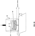
- FIG. 1B illustrates the position of an EC probe detection head 126 relative to surface 120 under inspection in accordance with an embodiment of the present invention.
- the primary coil device C1 along with measurement coils C2 and C3 (not shown in FIG. IB), is located within the probe detection head 126.
- the probe head detection 126 is contactively applied to the surface 120 under inspection (e.g., an R1 rotor blade).
- the distance between Coil C1 and surface 120 is called lift-off, which affects the mutual inductance of the coils.
- the lift-off may be in the range of 0.2-0.4 millimeters (mm).
- the distance between coil end 128 and surface 120 may be about 0.2 mm.
- outer-surface 130 of probe detection head 126 may comprise an additional protective layer (not shown) having a thickness of about 0.2 mm (e.g., 0.2 mm of PTFE adhesive tape).
- FIGS. 2A-2C illustrate the mechanical construction and relative positioning of an EC probe device 202 relative a gas turbine system rotor blade under inspection in accordance with an embodiment of the present invention.
- the EC probe device 202 comprises a probe detection head 204, a probe stem 206, and a probe guide 208 or extended handle.
- the size of the probe device 202 relative to rotor blades 210a, 210b, and 210c is exaggerated for aiding the illustrative process.
- the length of the probe head 204 relative to the length of the fillet section 214 of each of the rotor blades is around 1/6.
- the length of the probe guide 208 may be in the region of 30 centimeters (cm), while the probe stem may have a length of about 5 cm.
- the axis of the probe guide 208 may be substantially perpendicular to the axis of the probe stem 206, whereby the probe guide 208 facilitates the manipulation of the probe device 202 into measurement position such that physical contact is established between the probe head 204 and the fillet section 214 of rotor blade 210a. This is also illustrated with the aid of the expanded view of region 205 shown in FIG. 2B .
- the fillet region 214 of rotor blade 210a is a region located between platform 224 and airfoil 226.
- the fillet region of the rotor blades are of particular interest in detecting corrosion pitting according to the described embodiments of the present invention.
- the probe head 204 is manipulated to contactively slide along the length of the fillet 214 between fillet edge 218a and 218b in the Z direction. During this sliding motion, the angle between the axis of the probe stem 206 and horizontal plane is kept relatively constant.
- the probe head 204 is manipulated to contactively slide along the length of the fillet 214 multiple times.
- the probe stem 206 is rotated in the XY plane in order to form a new angle between the axis of the probe stem 206 and the horizontal plane.
- the primary coil device C1 induces a primary magnetic field (B1) in a different area of the fillet 214.
- This angular variation in the probe stem 206 is illustrated in the cross sectional view of the rotor blade 210a depicted in FIG. 2C .
- the probe stem is rotated in the XY plane to form three angles between the axis of the probe stem 206 and horizontal plane 230. More specifically, firstly, the probe head 204 is manipulated to contactively slide along the length of the fillet 214 at an angle of 15 degrees, as defined by 232. Second, the probe head 204 is manipulated to contactively slide along the length of the fillet 214 a second time at an angle of 45 degrees, as defined by 234. Finally, the probe head 204 is manipulated to contactively slide along the length of the fillet 214 at an angle of 75 degrees for a third and final time, as defined by 236.
- the number or slides and angles utilized during detection measurements can be varied. However, once a corrosion pit is detected, the probe head 204 is manipulated to contact that particular corrosion affected area Once in the corrosion affected area, the angle between the axis of the probe stem 206 and horizontal plane 230 can be varied to determine whether other corrosion pits are also present in that particular section of the fillet 214.
- FIG. 3 illustrates an imaging device 302 used in cooperation with an EC probe device 304 in accordance with an embodiment of the present invention.
- the imaging device 302 e.g., video camera
- the imaging device 302 may be located in proximity to the probe device's 304 probe detection head 306 for the purpose of providing the user of the device 304 with an enhanced visual view of the fillet portion 310 of the rotor blade 312 under inspection.
- the captured images may be displayed to the user on a handheld or portable video monitor 314.
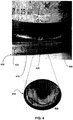
- FIG. 4 illustrates a photographic image of a calibration block 402 used in the generation of the reference data that is stored in the reference data storage medium 114 ( FIG.1 ) according to an embodiment of the present invention.
- the calibration block comprises a plurality of pre-generated corrosion pitting areas 404, 406, 408 that are created on a sample fillet surface 310 using electrical discharge machining (EDM).
- EDM electrical discharge machining
- the illustrated example shows several pre-generated corrosion pitting areas 404, 406, 408 each having different diameters and depths that have been accurately formed on the sample fillet surface 310 using EDM.
- Pre-generated corrosion pit area 404 includes a diameter of 0.25 mm and a depth of 0.25 mm.
- Pre-generated corrosion pit area 406 includes a diameter of 0.50 mm and a depth of 0.50 mm. Also, pre-generated corrosion pit area 408 includes a diameter of 0.75 mm and a depth of 0.75 mm. As defined at 414, an expanded view of pre-generated corrosion pit 406 is provided.
- each measurement will generate a specific signal amplitude that corresponds to each of pre-generated corrosion pitting areas 404, 406, 408. Therefore, each amplitude correlates with a particular corrosion pit having a known geometry. These signal amplitudes and their corresponding geometries form at least some of the reference data that is stored. In this manner signal amplitudes that are generated during field tests are correlated with the reference data in order to determine the existence of corrosion pitting. The approximate geometry of any detected corrosion pit is also provided.
- FIG. 5 illustrates an operational flow diagram 500 associated with EC probe device 100 ( FIG. 1 ) according to an embodiment of the present invention.
- Flow diagram 500 is described with the aid of FIGS 1 and 2 .
- a user accesses the inlet guide veins (IGVs) and the R1 rotor blades located directly behind the IGVs using an opening in the intake plenum at the front of the compressor mouth (i.e., bell mouth) of a gas turbine.
- IGVs inlet guide veins
- R1 rotor blades located directly behind the IGVs using an opening in the intake plenum at the front of the compressor mouth (i.e., bell mouth) of a gas turbine.
- a probe detection head having a radius of curvature less than or substantially the same as the fillet section of the R1 rotor blades under inspection is selected.
- radius R ( FIG. 2B ) of the probe detection head 204 ( FIG. 2B ) is designed to be slightly less than the radius of curvature of the fillet section 214 ( FIG. 2B ).
- the probe head 204 is applied to the first edge 218a ( FIG. 2B ) of the fillet 214.
- the angle between the probe stem 206 ( FIG. 2B ) and the horizontal plane 230 ( FIG. 2C ) is then set at a relatively constant value of around, for example, 15 degrees, as defined at 232 ( FIG. 2C ).
- the drive coil C1 ( FIG. 1A ) within the probe head 204 applies a primary magnetic field to the area corresponding to the first edge 218a ( FIG. 2B ) of the fillet 214.
- a second magnetic field is detected based on the current induced in the conductive surface of the first edge 218a ( FIG. 2B ) area of the fillet 214 (step 512).
- an amplitude signal may be generated and processed by the differential amplifier 108 ( FIG. 1A ) and the signal processing device 112 ( FIG. 1A ) on the basis of a detected corrosion pit (step 514).
- step 516 it is determined whether the probe head 204 has reached the second edge 218b ( FIG. 2B ) area of the fillet 214. If (YES) the probe head 204 has reached the second edge 218b ( FIG. 2B ) area (step 516), it is determined whether the repositioning of the probe angle between the probe stem 206 ( FIG. 2B ) axis and the horizontal plane 230 ( FIG. 2C ) has been completed (step 520). For example, if the probe head 204 is operated using three angles of 15, 45, and 75 degrees, the repositioning is completed if measurements are carried out for all three angles of 15, 45, and 75 degrees. If (YES) repositioning is completed (step 520), the process of operational flow diagram 500 is repeated for another R1 rotor blade (step 524).
- step 520 If (NO) repositioning is not complete (step 520), the probe angle between the probe stem 206 ( FIG. 2B ) axis and the horizontal plane 230 ( FIG. 2C ) is changed to the next desired angle (step 522). For example, if the probe head 204 is operated using three angles of 15, 45, and 75 degrees, and the current angle is 15 degrees, the probe is then manipulated to the next angular setting to form a 45 degree angle. Following step 522, process steps 506, 508, 510, 512, 514, and 516 are then repeated.
- step 516 If (NO) at step 516, the probe head 204 has not reached the second edge 218b ( FIG. 2B ) area, the probe head 204 is applied to another section of the fillet 214 by sliding along the Z axis ( FIG. 2B ) direction of the fillet 214 (step 518). Following step 518, process steps 510, 512, 514, and 516 are repeated.
- FIG. 6 shows an operation flow diagram 600 for the signal processing performed by the EC probe device 100 ( FIG. 1A ) in detecting a corrosion pit according to an embodiment of the present invention.
- a net magnetic field is detected by measurement coil C2 ( FIG. 1A ).
- a net magnetic field is also detected by measurement coil C3 ( FIG. 1A ).
- the net magnetic field is a function of the interaction between the primary magnetic field generated by coil C1 ( FIG. 1A ) and the magnetic field generated by the eddy-currents induced in the conductive surface of the fillet 214 ( FIG. 1B ).
- the differential amplifier 108 ( FIG. 1A ) generates a signal amplitude when a different net magnetic field is experienced between measurement coils C2 and C3. For example, if measurement coils C2 and C3 are receiving a net magnetic field from the surface of the fillet 214 having no corrosion pits, the current magnitude induced in both measurement coils will be substantially the same. Thus, the differential amplifier 108 will not generate a signal exhibiting an increase in amplitude. However, if measurement coil C2 receives a net magnetic field from an area of the fillet 214 where there is a corrosion pit, the corrosion pit will disrupt the flow of eddy-currents in that area such that the net magnetic field detected by coil C2 changes relative to the net magnetic field detected by coil C3. Under these conditions, the differential amplifier 108 will generate a signal exhibiting an increase in amplitude.
- step 608 it determined whether the signal generated by the differential amplifier 108 exceeds a predetermined threshold value. This threshold detection is carried out within signal processing device 112. If (NO) the signal generated by the differential amplifier 108 fails to exceed the predetermined threshold value, process steps 602, 604, and 606 are repeated. If (YES) the signal generated by the differential amplifier 108 exceeds the predetermined threshold value (step 608), additional signal processing (e.g., digital filtering, equalization, etc.) may be carried out within signal processing device 112 (Step 610).
- additional signal processing e.g., digital filtering, equalization, etc.
- the signal processing device 112 accesses the reference data storage medium 114 in order to utilize the stored reference data.
- the stored reference data includes premeasured amplitude values that correspond to various pre-generated corrosion pits.
- the signal processing device 112 uses the accessed reference data to correlate the detected amplitude signal generated by the differential amplifier 108 with one of the premeasured amplitude values of the accessed reference data (step 614).
- data information e.g., corrosion pit geometry
- data information e.g., time-stamp data, pit geometry data, etc.
- data log storage medium 116 e.g., time-stamp data, pit geometry data, etc.
- FIG. 7 illustrates experimental performance data associated with determining the operating parameters of an EC probe device such as EC probe device 100 ( FIG. 1A ) according to an embodiment of the present invention.
- Graph 702 shows the repeatability of measurements carried out by an EC probe operated over a frequency range of 100-600 KHz. The frequency range applies to frequencies used to drive the primary coil of the EC probe under evaluation. As shown, frequencies in the range of 300-400 KHz desirably provide relatively the same measurement repeatability (e.g., detected amplitude values).
- Graph 704 shows a measure of standard deviation associated with the detected signal amplitudes over a frequency range of 100-600 KHz. As shown, frequencies in the range of 300-400 KHz also provide a relatively constant standard deviation for the amplitude values detected by the EC probe.
- Graph 706 shows a measure of signal-to-noise (S/N) ratio associated with the detected signal amplitudes over a frequency range of 100-600 KHz. As shown, in relation to the amplitude values detected by the EC probe, frequencies in the range of 300-400 KHz also exhibit the highest S/N ratios. Therefore, using such experimental evaluations, a suitable range of operating frequencies (e.g., 300-400 KHz) may be determined for a particular EC probe device.
- S/N signal-to-noise
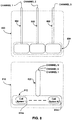
- a multi-channel EC probe device may be provided, where each channel accesses measurement data.
- a three channel device may be utilized.
- a multi-channel probe device 800 may include three discrete probe devices 802 that are configured such that their respective probe detection heads are coupled to each other to form a longitudinally enlarged probe head 804.
- Each discrete probe device 802 constitutes a single channel and may, for example, comprise the same design as EC probe device 100 ( FIG. 1A ).
- a multi-channel EC probe 810 may comprise a single probe head 812 incorporating multiple coil systems 814a-814n, whereby each coil system may, for example, include the same configuration as coil system 104 ( FIG. 1A ).
- the stem 820 of multi-channel EC probe 810 may house a signal multiplexer (not shown) that sequentially reads received signals from each coil system 814a-814n.
- the processing of the received signals may be carried out using either an individual processing device (e.g., device 112, FIG.1A ) or a parallel processing approach incorporating multiple processing devices (e.g., multiple devices 112, FIG.1A ). It will be appreciated that a myriad of different processing architectures may be employed in the accessing and processing of multiple channels.
Landscapes
- Chemical & Material Sciences (AREA)
- Chemical Kinetics & Catalysis (AREA)
- Electrochemistry (AREA)
- Physics & Mathematics (AREA)
- Health & Medical Sciences (AREA)
- Life Sciences & Earth Sciences (AREA)
- Analytical Chemistry (AREA)
- Biochemistry (AREA)
- General Health & Medical Sciences (AREA)
- General Physics & Mathematics (AREA)
- Immunology (AREA)
- Pathology (AREA)
- Investigating Or Analyzing Materials By The Use Of Magnetic Means (AREA)
- Turbine Rotor Nozzle Sealing (AREA)
- Testing Resistance To Weather, Investigating Materials By Mechanical Methods (AREA)
Description
- The present invention relates generally to the detection of corrosion in gas turbine systems, and, more particularly, to an apparatus and method for providing in-situ detection of corrosion pitting in gas turbine compressor blades.
-
US 6 452 384 B1 discloses a scanning head for eddy-current testing including a probe coil configuration disposed on a film.US 5 623 204 A discloses an eddy current probe including an eddy current test assembly formed in the outer surface of a shoe that rotates within a tubular test specimen. - As a fuel with low CO2 emissions, natural gas has experienced a major expansion worldwide. When distance and topography between gas fields and consumer markets do not allow pipeline transport, the gas can be reduced to, for example, 1/600th of its free volume by liquefaction. Liquefied Natural Gas (LNG) plants liquefy purified natural gas in cryogenic heat exchangers so that the purified liquid natural gas can be stored in tanks prior to being loaded on designed tankers for transportation between an LNG plant and consumer regions. At the consumer regions, the LNG product is unloaded in an LNG receiving terminal, pumped up to pipeline pressure, and re-gasified for feeding into the buyer's natural gas pipeline grid.
- In response to these increased demands, the size of LNG plants has, therefore, grown considerably over the past few decades. This, in turn, has contributed to lowering LNG production costs, while at the same time increasing the competitivity of the LNG marketplace. For example, in the 1980s, it was common practice to produce 2-3 million tons per steam per year. Present units produce 4-5 million tons per year, and engineering companies are now (i.e., 2009) planning plants with unit capacities in the order of 7-8 million tons per year.
- In LNG plants, it is common practice to use, for example, gas turbines to drive the refrigerating compressors utilized in the cryogenic heat exchangers responsible for the liquefaction of natural gas. Thus, production output may be closely associated with reliable plant operation, in particular, gas turbine reliability. The reliable operation of gas turbine systems may be hampered by a myriad of different failure causes. As described in the following paragraphs, one such cause is the adverse effect of corrosion on the Inlet Guide Vanes (IGVs) and rotor blades of the gas turbine's turbo compressor.
- LNG plants are typically located in marine coastal environments, where corrosive elements such as Chlorides and Sulphides are prevalent in the atmosphere. The Chlorides originate as a result of proximity to the sea, while the Sulphides are generated by the LNG plant's gas flares. The air filtration system of a gas turbine needs both correct design and maintenance, especially since it provides the key to the successful operation and reliability of the overall plant by purifying air that is inlet into the combustion section of the gas turbine system. Despite attempts to maintain reliable and effective air filtration, the presence of corrosive elements such as Chlorides and Sulphides in the various stages of the gas turbine system, such as, the axial compressor blades of the gas turbine (e.g., IGVs and R1 rotor blades) is unavoidable. These elements (i.e., Chlorides and Sulphides) may, for example, corrode the material construction of the gas turbine's IGVs and first stage (R1) rotor blades by causing corrosion pitting, which if undetected, eventually leads to the initiation and propagation of cracks within the blades. The consequences of such cracks are breakages in one or more of gas turbine's IGVs and R1 rotor blades, thus, causing an eventual gas turbine outage.
- These outages are extremely costly. Usually, there is zero-redundancy associated with the production machinery/equipment of LNG plants. Within a given gas turbine train, the outage of one gas turbine can cause an overall train outage or, at least, a vast reduction of LNG production rate. As a consequence, LNG shipment may also be postponed, generating additional costs and/or profit losses that may be estimated in the range of $2 - $7 Million Dollars/day depending on the specific plant size and production plan. For this reason all catastrophic failures, such as those generated by corrosion pitting, should be avoided since an outage of 7-10 days duration is the expected duration for restoring the system back to an operational status.
- Thus, in order to avoid a gas turbine outage situation as a result of undetected failure conditions, it would be advantageous to provide in-situ corrosion detection within LNG gas turbine systems without the need for disassembling the gas turbine system (e.g., casing).
- The present invention is defined in the accompanying claims.
- Various embodiments of the present invention provide methods and apparatuses for detecting corrosion pitting in turbine blades.
- It will be appreciated by those skilled in the art that the foregoing brief description and the following detailed description are exemplary and explanatory of the present invention, but are not intended to be restrictive thereof or limiting of the advantages which can be achieved by this invention. Additionally, it is understood that the foregoing summary of the invention is representative of some embodiments of the invention, and is neither representative nor inclusive of all subject matter and embodiments within the scope of the present invention. Thus, the accompanying drawings, referred to herein and constituting a part hereof, illustrate embodiments of this invention, and, together with the detailed description, serve to explain principles of this invention.
- Aspects, features, and advantages of embodiments of the invention, both as to structure and operation, will be understood and will become more readily apparent when the invention is considered in the light of the following description made in conjunction with the accompanying drawings, in which like reference numerals designate the same or similar parts throughout the various figures, and wherein:
-
FIG. 1A illustrates a block diagram of an Eddy Current (EC) probe device in accordance with an embodiment of the present invention; -
FIG. 1B illustrates the position of the EC probe head relative to surface under inspection in accordance with an embodiment of the present invention; -
FIGS. 2A-2C illustrate the mechanical construction and relative positioning of the EC probe device relative a gas turbine system rotor blade under inspection in accordance with an embodiment of the present invention; -
FIG. 3 illustrates an imaging device used in cooperation with the EC probe device in accordance with an embodiment of the present invention; -
FIG. 4 illustrates a photographic image of acalibration block 402 used in the generation of stored reference data according to an embodiment of the present invention; -
FIG. 5 illustrates an operation flow diagram of the EC probe device according to an embodiment of the present invention; -
FIG. 6 illustrates an operation flow diagram of the signal processing performed by the EC probe device according to an embodiment of the present invention; -
FIG. 7 illustrates experimental performance data associated with determining the operating parameters of the EC probe device according to an embodiment of the present invention; and -
FIG. 8 illustrates an example of a unit incorporating a multi-channel EC probe device in accordance with an embodiment of the present invention. - The following describes various embodiments and aspects of the present invention that utilizes Eddy Currents (EC) for the detection and analysis of the corrosive characteristics (e.g., corrosion pitting) found in gas turbine rotor blades. Accordingly, a novel EC detection probe and application methodology is provided for detecting corrosion pitting in the first stages of gas turbine rotor blades. The first stages of the gas turbine rotor blades (i.e., R1 rotor blades) are typically more susceptible to corrosion pitting. Moreover, using the probe device, the first stage rotor blades (i.e., Rl) are directly accessible by a user via an opening in the intake plenum of the gas turbine.
- The corrosively generated pits ("a corrosion pit") may or may not be substantially circular and generally include indentations in a material's surface. These indentations, although very small (i.e., typically having depths and diameters of less than 1 millimeter), lead to more serious defects such as cracks. In the case of the first stages (i.e., Rl) of a gas turbine's rotor blades, detection of corrosion pitting avoids the subsequent initiation and propagation of cracks, whereby the creation of such cracks can lead to rotor blade breakages during the operations of a gas turbine and thus leading to a catastrophic failure. While cracks provide a sharp discontinuity that makes them suitable for conventional detection via signal phase changes using EC detection equipment, a corrosion pit does not exhibit such a sharp discontinuity. Therefore, according to at least one embodiment of the present invention, sensitive receiver designs may be utilized for the detection of signal amplitude changes resulting from the presence of a corrosion pit.
-
FIG. 1A schematically depicts anEC probe device 100 in accordance with an embodiment of the present invention.Device 100 comprises aprimary coil driver 102, acoil system 104, band-pass (BP)filters differential amplifier 108, an analog-to-digital (A/D)convertor 110, asignal processing device 112, a referencedata storage medium 114, a datalog storage medium 116, and a detection indicator 118 (e.g., a visual display, audio buzzer). The operation of theEC probe device 100 is further explained in relation to the flow diagrams illustrated inFIG. 5 andFIG. 6 . - The
primary coil driver 102 includes an electrical signal source that provides an alternating drive signal (e.g., sinusoidal signal, pulsed signal, ramped signal, etc.) to thecoil system 104 for inducing eddy currents in thesurface 120 of the material under inspection (i.e., fillet portion of gas turbine R1 rotor blades).Coil system 104 may include three coil devices, as illustrated in the expandedbottom view 122. As depicted at 122, coil C1 is a primary coil device operable to generate a primary magnetic field (B1) that is induced insurface 120, which produces eddy currents within thesurface 122. Coil devices C2 and C3 are measurement coils used to receive a net magnetic field comprised of the interaction between the generated primary magnetic field (B1) and the generated eddy current magnetic field (B2) fromsurface 122. As previously mentioned, sensitive receiver designs may be utilized for the detection of signal amplitude changes resulting from the presence of a corrosion pit. One such design consideration applies to the measurement coils (i.e., C2, C3). These coils should exhibit a coil diameter that has a comparable geometry (e.g., diameter) to that of the indentations caused by corrosion pitting. For example, a coil diameter of 1.6mm may be used to detect corrosion pits having diameters of 0.25 mm, 0.50 mm, and 0.75 mm, and a depth of 0.25 mm, 0.50 mm, and 0.75 mm, respectively. - Measurement coil devices C2 and C3 are each coupled to the inputs of
BP filters EC probe device 100 relative to measurement area when, for example, the device is utilized as a hand-held device. In addition, BP filters 106a and 106b also enhance the signal-to-noise (S/N) ratio of the signals received by coil devices C2 and C3, respectively. - The output from
BP filters differential amplifier 108. When no defects are present onsurface 122, the filtered inputs received from the BP filters 106a, 106b at the differential inputs of thedifferential amplifier 108 are substantially the same. Consequently, thedifferential amplifier 108 generates an output voltage of low signal amplitude close to zero. Alternatively, if defects are present onsurface 122, the filtered inputs received from the BP filters 106a, 106b at the differential inputs of thedifferential amplifier 108 are not the same. Consequently, thedifferential amplifier 108 generates an increased output voltage. As one of the measurement coils (i.e., C2 or C3) moves over a pitted area (due to corrosion), the reactive component of this coil (e.g., C2) changes relative to the other coil (e.g., C3). This in turns causes a differential change in signal current that is applied to thedifferential amplifier 108 and, thus, an increase in output voltage. The amplitude of the generated output signal may depend on several factors such as, but not limited to, the geometry of the pit (e.g., 0.3x0.45 millimeters), the sensitivity of the measurement coils to changes in eddy-current-induced magnetic fields caused by the pit, and the optimization of the electrical drive parameters associated with the coil driver 102 (e.g., waveform, amplitude, and frequency of the signal driving the primary coil). The generated output signal may be converted from an analog to a digital format by A/D convertor 110 prior to being processed at thesignal processing device 112. Alternatively, the analog to a digital conversion may be performed within thesignal processing device 112 without the need for a separate device such as A/D convertor 110. - The
signal processing device 112 provides various processing on the digitized amplitude signals output from thedifferential amplifier 108. For example, thesignal processing device 112 performs threshold detection in order to determine whether the detected amplitude constitutes an amplitude signal caused by the detection of a corrosion pit.Signal processing device 112 also accesses reference data from the referencedata storage medium 114 in order to correlate the received amplitude signal with existing reference data (e.g., various digitized amplitude values) entered in the referencedata storage medium 114. Each reference data entry found within referencedata storage medium 114 provides information associated with a corrosion pit having a specific geometry and/or dimension. Additional digital signal processing (DSP) such as digital filtering and equalization may also be carried out on the received amplitude signals in order to further aid the detection of corrosion pits. - The
detection indicator 118 alerts a user of theprobe device 100 once it has been determined that a corrosion pit has been detected. Thedetection indicator 118 may comprise a visual indicator such as a light emitting device (e.g., LED) and/or an audio indicator such as a buzzer. - The signal
log storage medium 116 stores data information associated with each detected corrosion pit. Once thesignal processing device 112 confirms the detection of a corrosion pit, it stores the detected amplitude value along with time-stamp information within the signallog storage medium 116. The time-stamp may comprise date (e.g., year/month/day) and time (e.g., 24 hour clock) information associated with each detected corrosion pit, which may, among other uses, provide a means for calculating the different time intervals between the different occurrences of detecting corrosion pitting in the gas turbine rotor blades. The signallog storage medium 116 may also store drive signal information corresponding to each of the detected amplitude values and time-stamp information. The stored drive signal information may include the amplitude characteristics, shape, and frequency of the signal applied to primary coil C1 based on the detection of a corrosion pit. - Although
FIG. 1A illustrates a separate referencedata storage medium 114 and signallog storage medium 116, both storage mediums (i.e., 114 and 116) may be integrated within thesignal processing device 112. -
FIG. 1B illustrates the position of an ECprobe detection head 126 relative to surface 120 under inspection in accordance with an embodiment of the present invention. As shown, the primary coil device C1, along with measurement coils C2 and C3 (not shown in FIG. IB), is located within theprobe detection head 126. In operation, theprobe head detection 126 is contactively applied to thesurface 120 under inspection (e.g., an R1 rotor blade). The distance between Coil C1 andsurface 120 is called lift-off, which affects the mutual inductance of the coils. In the example shown inFIG. 1B , the lift-off may be in the range of 0.2-0.4 millimeters (mm). The distance betweencoil end 128 andsurface 120 may be about 0.2 mm. In addition, outer-surface 130 ofprobe detection head 126 may comprise an additional protective layer (not shown) having a thickness of about 0.2 mm (e.g., 0.2 mm of PTFE adhesive tape). -
FIGS. 2A-2C illustrate the mechanical construction and relative positioning of anEC probe device 202 relative a gas turbine system rotor blade under inspection in accordance with an embodiment of the present invention. As shown inFIG. 2A , theEC probe device 202 comprises aprobe detection head 204, aprobe stem 206, and a probe guide 208 or extended handle. InFIG. 2A , the size of theprobe device 202 relative torotor blades probe head 204 relative to the length of thefillet section 214 of each of the rotor blades is around 1/6. The length of the probe guide 208 may be in the region of 30 centimeters (cm), while the probe stem may have a length of about 5 cm. - The axis of the probe guide 208 may be substantially perpendicular to the axis of the
probe stem 206, whereby the probe guide 208 facilitates the manipulation of theprobe device 202 into measurement position such that physical contact is established between theprobe head 204 and thefillet section 214 ofrotor blade 210a. This is also illustrated with the aid of the expanded view ofregion 205 shown inFIG. 2B . - As shown in
FIG. 2B , thefillet region 214 ofrotor blade 210a is a region located betweenplatform 224 andairfoil 226. The fillet region of the rotor blades are of particular interest in detecting corrosion pitting according to the described embodiments of the present invention. During corrosion pitting detection, theprobe head 204 is manipulated to contactively slide along the length of thefillet 214 betweenfillet edge probe stem 206 and horizontal plane is kept relatively constant. Theprobe head 204 is manipulated to contactively slide along the length of thefillet 214 multiple times. Each time, theprobe stem 206 is rotated in the XY plane in order to form a new angle between the axis of theprobe stem 206 and the horizontal plane. By changing the angle, the primary coil device C1 induces a primary magnetic field (B1) in a different area of thefillet 214. By contactively sliding theprobe head 204 along the length of thefillet 214 at different angles, corrosion detection measurements covering the entire fillet region is facilitated. - This angular variation in the
probe stem 206 is illustrated in the cross sectional view of therotor blade 210a depicted inFIG. 2C . According to the example shown inFIG. 2C , during the corrosion detection measurements, the probe stem is rotated in the XY plane to form three angles between the axis of theprobe stem 206 andhorizontal plane 230. More specifically, firstly, theprobe head 204 is manipulated to contactively slide along the length of thefillet 214 at an angle of 15 degrees, as defined by 232. Second, theprobe head 204 is manipulated to contactively slide along the length of the fillet 214 a second time at an angle of 45 degrees, as defined by 234. Finally, theprobe head 204 is manipulated to contactively slide along the length of thefillet 214 at an angle of 75 degrees for a third and final time, as defined by 236. - The number or slides and angles utilized during detection measurements can be varied. However, once a corrosion pit is detected, the
probe head 204 is manipulated to contact that particular corrosion affected area Once in the corrosion affected area, the angle between the axis of theprobe stem 206 andhorizontal plane 230 can be varied to determine whether other corrosion pits are also present in that particular section of thefillet 214. -
FIG. 3 illustrates animaging device 302 used in cooperation with anEC probe device 304 in accordance with an embodiment of the present invention. The imaging device 302 (e.g., video camera) may be located in proximity to the probe device's 304probe detection head 306 for the purpose of providing the user of thedevice 304 with an enhanced visual view of thefillet portion 310 of therotor blade 312 under inspection. The captured images may be displayed to the user on a handheld orportable video monitor 314. -
FIG. 4 illustrates a photographic image of acalibration block 402 used in the generation of the reference data that is stored in the reference data storage medium 114 (FIG.1 ) according to an embodiment of the present invention. The calibration block comprises a plurality of pre-generatedcorrosion pitting areas sample fillet surface 310 using electrical discharge machining (EDM). The illustrated example shows several pre-generatedcorrosion pitting areas sample fillet surface 310 using EDM. Pre-generatedcorrosion pit area 404 includes a diameter of 0.25 mm and a depth of 0.25 mm. Pre-generatedcorrosion pit area 406 includes a diameter of 0.50 mm and a depth of 0.50 mm. Also, pre-generatedcorrosion pit area 408 includes a diameter of 0.75 mm and a depth of 0.75 mm. As defined at 414, an expanded view ofpre-generated corrosion pit 406 is provided. - When an EC probe device such as device 100 (
FIG. 1 ) performs a corrosion pit measure on the pre-generatedcorrosion pitting areas corrosion pitting areas -
FIG. 5 illustrates an operational flow diagram 500 associated with EC probe device 100 (FIG. 1 ) according to an embodiment of the present invention. Flow diagram 500 is described with the aid ofFIGS 1 and2 . At step, 502, a user accesses the inlet guide veins (IGVs) and the R1 rotor blades located directly behind the IGVs using an opening in the intake plenum at the front of the compressor mouth (i.e., bell mouth) of a gas turbine. - At
step 504, a probe detection head having a radius of curvature less than or substantially the same as the fillet section of the R1 rotor blades under inspection is selected. For example, radius R (FIG. 2B ) of the probe detection head 204 (FIG. 2B ) is designed to be slightly less than the radius of curvature of the fillet section 214 (FIG. 2B ). - At
step 506, theprobe head 204 is applied to thefirst edge 218a (FIG. 2B ) of thefillet 214. Atstep 508, the angle between the probe stem 206 (FIG. 2B ) and the horizontal plane 230 (FIG. 2C ) is then set at a relatively constant value of around, for example, 15 degrees, as defined at 232 (FIG. 2C ). - At
step 510, the drive coil C1 (FIG. 1A ) within theprobe head 204 applies a primary magnetic field to the area corresponding to thefirst edge 218a (FIG. 2B ) of thefillet 214. Using the measurement coils C2, C3 (FIG. 1A ) within theprobe head 204, a second magnetic field is detected based on the current induced in the conductive surface of thefirst edge 218a (FIG. 2B ) area of the fillet 214 (step 512). Based on the received second magnetic field by coils C2 and C3, an amplitude signal may be generated and processed by the differential amplifier 108 (FIG. 1A ) and the signal processing device 112 (FIG. 1A ) on the basis of a detected corrosion pit (step 514). - At
step 516, it is determined whether theprobe head 204 has reached thesecond edge 218b (FIG. 2B ) area of thefillet 214. If (YES) theprobe head 204 has reached thesecond edge 218b (FIG. 2B ) area (step 516), it is determined whether the repositioning of the probe angle between the probe stem 206 (FIG. 2B ) axis and the horizontal plane 230 (FIG. 2C ) has been completed (step 520). For example, if theprobe head 204 is operated using three angles of 15, 45, and 75 degrees, the repositioning is completed if measurements are carried out for all three angles of 15, 45, and 75 degrees. If (YES) repositioning is completed (step 520), the process of operational flow diagram 500 is repeated for another R1 rotor blade (step 524). - If (NO) repositioning is not complete (step 520), the probe angle between the probe stem 206 (
FIG. 2B ) axis and the horizontal plane 230 (FIG. 2C ) is changed to the next desired angle (step 522). For example, if theprobe head 204 is operated using three angles of 15, 45, and 75 degrees, and the current angle is 15 degrees, the probe is then manipulated to the next angular setting to form a 45 degree angle. Followingstep 522, process steps 506, 508, 510, 512, 514, and 516 are then repeated. - If (NO) at
step 516, theprobe head 204 has not reached thesecond edge 218b (FIG. 2B ) area, theprobe head 204 is applied to another section of thefillet 214 by sliding along the Z axis (FIG. 2B ) direction of the fillet 214 (step 518). Followingstep 518, process steps 510, 512, 514, and 516 are repeated. -
FIG. 6 shows an operation flow diagram 600 for the signal processing performed by the EC probe device 100 (FIG. 1A ) in detecting a corrosion pit according to an embodiment of the present invention. Atstep 602, a net magnetic field is detected by measurement coil C2 (FIG. 1A ). Similarly, atstep 604, a net magnetic field is also detected by measurement coil C3 (FIG. 1A ). The net magnetic field is a function of the interaction between the primary magnetic field generated by coil C1 (FIG. 1A ) and the magnetic field generated by the eddy-currents induced in the conductive surface of the fillet 214 (FIG. 1B ). - At
step 606, the differential amplifier 108 (FIG. 1A ) generates a signal amplitude when a different net magnetic field is experienced between measurement coils C2 and C3. For example, if measurement coils C2 and C3 are receiving a net magnetic field from the surface of thefillet 214 having no corrosion pits, the current magnitude induced in both measurement coils will be substantially the same. Thus, thedifferential amplifier 108 will not generate a signal exhibiting an increase in amplitude. However, if measurement coil C2 receives a net magnetic field from an area of thefillet 214 where there is a corrosion pit, the corrosion pit will disrupt the flow of eddy-currents in that area such that the net magnetic field detected by coil C2 changes relative to the net magnetic field detected by coil C3. Under these conditions, thedifferential amplifier 108 will generate a signal exhibiting an increase in amplitude. - At
step 608, it determined whether the signal generated by thedifferential amplifier 108 exceeds a predetermined threshold value. This threshold detection is carried out withinsignal processing device 112. If (NO) the signal generated by thedifferential amplifier 108 fails to exceed the predetermined threshold value, process steps 602, 604, and 606 are repeated. If (YES) the signal generated by thedifferential amplifier 108 exceeds the predetermined threshold value (step 608), additional signal processing (e.g., digital filtering, equalization, etc.) may be carried out within signal processing device 112 (Step 610). - At
step 612, thesignal processing device 112 accesses the referencedata storage medium 114 in order to utilize the stored reference data. As previously described, the stored reference data includes premeasured amplitude values that correspond to various pre-generated corrosion pits. Using the accessed reference data, thesignal processing device 112 correlates the detected amplitude signal generated by thedifferential amplifier 108 with one of the premeasured amplitude values of the accessed reference data (step 614). - Based on the correlated premeasured amplitude value, data information (e.g., corrosion pit geometry) associated with the detected corrosion pit is also accessed from the reference
data storage medium 114 using the signal processing device 112 (step 616). Data information (e.g., time-stamp data, pit geometry data, etc.) associated with the detected corrosion pit may then be logged by thesignal processing device 112 in the data log storage medium 116 (step 618). -
FIG. 7 illustrates experimental performance data associated with determining the operating parameters of an EC probe device such as EC probe device 100 (FIG. 1A ) according to an embodiment of the present invention.Graph 702 shows the repeatability of measurements carried out by an EC probe operated over a frequency range of 100-600 KHz. The frequency range applies to frequencies used to drive the primary coil of the EC probe under evaluation. As shown, frequencies in the range of 300-400 KHz desirably provide relatively the same measurement repeatability (e.g., detected amplitude values). -
Graph 704 shows a measure of standard deviation associated with the detected signal amplitudes over a frequency range of 100-600 KHz. As shown, frequencies in the range of 300-400 KHz also provide a relatively constant standard deviation for the amplitude values detected by the EC probe. -
Graph 706 shows a measure of signal-to-noise (S/N) ratio associated with the detected signal amplitudes over a frequency range of 100-600 KHz. As shown, in relation to the amplitude values detected by the EC probe, frequencies in the range of 300-400 KHz also exhibit the highest S/N ratios. Therefore, using such experimental evaluations, a suitable range of operating frequencies (e.g., 300-400 KHz) may be determined for a particular EC probe device. - It may be possible to incorporate several EC probe devices into a single unit in order to conduct measurements over an increased surface area of a filet section. In such a configuration, a multi-channel EC probe device may be provided, where each channel accesses measurement data. For example, a three channel device may be utilized. Such examples are shown in
Fig. 8 . According to one embodiment, amulti-channel probe device 800 may include threediscrete probe devices 802 that are configured such that their respective probe detection heads are coupled to each other to form a longitudinallyenlarged probe head 804. Eachdiscrete probe device 802 constitutes a single channel and may, for example, comprise the same design as EC probe device 100 (FIG. 1A ). According to another embodiment, amulti-channel EC probe 810 may comprise asingle probe head 812 incorporatingmultiple coil systems 814a-814n, whereby each coil system may, for example, include the same configuration as coil system 104 (FIG. 1A ). Thestem 820 ofmulti-channel EC probe 810 may house a signal multiplexer (not shown) that sequentially reads received signals from eachcoil system 814a-814n. The processing of the received signals may be carried out using either an individual processing device (e.g.,device 112,FIG.1A ) or a parallel processing approach incorporating multiple processing devices (e.g.,multiple devices 112,FIG.1A ). It will be appreciated that a myriad of different processing architectures may be employed in the accessing and processing of multiple channels. - The present invention has been illustrated and described with respect to specific embodiments thereof, which embodiments are merely illustrative of the principles of the invention and are not intended to be exclusive or otherwise limiting embodiments. Accordingly, although the above description of illustrative embodiments of the present invention, as well as various illustrative modifications and features thereof, provides many specificities, these enabling details should not be construed as limiting the scope of the invention, and it will be readily understood by those persons skilled in the art that the present invention is susceptible to many modifications, adaptations, variations, omissions, additions, and equivalent implementations without departing from this scope and without diminishing its attendant advantages. For instance, except to the extent necessary or inherent in the processes themselves, no particular order to steps or stages of methods or processes described in this disclosure, including the figures, is implied. In many cases the order of process steps may be varied, and various illustrative steps may be combined, altered, or omitted, without changing the purpose, effect or import of the methods described. It is further noted that the terms and expressions have been used as terms of description and not terms of limitation. There is no intention to use the terms or expressions to exclude any equivalents of features shown and described or portions thereof. Additionally, the present invention may be practiced without necessarily providing one or more of the advantages described herein or otherwise understood in view of the disclosure and/or that may be realized in some embodiments thereof. It is therefore intended that the present invention is not limited to the disclosed embodiments but should be defined in accordance with the claims that follow.
Claims (12)
- A probe device (100) for detecting corrosion in one or more blades of a gas turbine system, the device comprising:(a) a detection head (126) having a shape arranged to conform to a surface geometry of a fillet section of a gas turbine blade, the detection head (126) being operable to move along the axial length of the fillet section for detecting corrosion pitting;(b) at least one primary coil device (C1) located within the detection head (126) and operable to induce a first magnetic field within an area of the fillet in contact with the detection head (126);(c) a receiver device (C2,C3,106a,106b,108) operable to detect a signal corresponding to a second magnetic field received from the area of the fillet exposed to the first magnetic field, wherein the second magnetic field is generated by induced currents in the area by the first magnetic field;(d) a storage medium (114) containing reference data with a plurality of premeasured signal amplitudes corresponding to corrosion pitting with known geometry; and(e) a signal processing device (112) configured to process the detected signal by correlating the amplitude of the detected signal with one of the plurality of the premeasured amplitude values and wherein the signal processing device (112) is further configured to determine the geometry and/or the dimensions of corrosion pitting in the inspected area based on the known corrosion pitting geometry associated with the correlated premeasured amplitude data;and wherein the receiver device comprises:(a) a first and a second coil device (C2, C3) disposed inside the primary coil operable to generate a first and a second received signal from the second magnetic field, respectively;(b) a first and a second band-pass filter device (106a, 106b) respectively coupled to the first and the second coil device (C2, C3), wherein the first and the second band-pass filter device (106a, 106b) are operable to filter the first and the second received signal, respectively; and(c) a differential amplifier device (108) coupled to the first and the second band-pass filter device (106a, 106b), wherein the differential amplifier is operable to differentially amplify the filtered first and the filtered second received signal and generate the detected signal;
- The device according to claim 1, wherein the detection head (126) comprises a substantially cylindrical shape including a radius arranged, in use, to correspond to a curvature radius of a fillet.
- The device according to any preceding claim, wherein the detection head (126) comprises a substantially cylindrical shape including a radius arranged, in use, to be less than or substantially equal to a curvature radius corresponding to a fillet.
- The device according to any preceding claim, further comprising a handle section coupled to the detection head (126), the handle section including a flexible portion operable to move the detection head (126) into a measurement position.
- The device according to claim 4, further comprising a video camera (302) coupled to the handle section, the video camera (302) located in proximity to the detection head (126) and operable to assist an operator move the detection head (126) into the measurement position.
- The device according to any preceding claim, further comprising a driver device (102) operable to generate a drive signal that is applied to the at least one coil device (C1), wherein the driver device (102) is arranged to manipulate at least one characteristic of the drive signal for producing a signal-to-noise ratio associated with the detected signal that exceeds a designated threshold.
- The device according to claim 6, wherein the at least one characteristic comprises drive signal amplitude.
- The device according to claim 6, wherein the at least one characteristic comprises drive signal frequency.
- The device according to claim 6, wherein the at least one characteristic comprises a combination of drive signal amplitude and drive signal frequency.
- A method of detecting corrosion in one or more blades of a gas turbine system, the method comprising:(a) detecting corrosion pitting along the axial length of a fillet section of a gas turbine blade by using a detection head (126) having a shape arranged to conform to the surface geometry of the fillet section;(b) inducing a first magnetic field by a primary coil device (C1) within an area of the filet during the detecting of the corrosion;(c) detecting first and second received signals generated by a first and a second coil device (C2,C3) corresponding to first and second magnetic fields received from the area of the fillet exposed to the induced first magnetic field, wherein the first and second magnetic fields are generated by induced currents in the area by the induced first magnetic field,(d) bandpass filtering the first and second received signals;(e) differentially amplifying the filtered first and second received signals and generating the detected signal;(f) processing the detected signal by accessing a reference database containing reference data with a plurality of premeasured signal amplitudes corresponding to corrosion pitting with known geometry and by correlating the amplitude of the detected signal with one of the plurality of the premeasured amplitude values; and(g) determining the geometry and/or the dimensions of corrosion pitting in the inspected area based on the known corrosion pitting geometry associated with the correlated premeasured amplitude data,wherein the geometry and/or the dimensions of the corrosion pitting is determined without any casing disassembly of the gas turbine system.
- The method according to claim 10, further comprising:(e) imaging the gas turbine blade using an imaging device (302) for facilitating the detecting of corrosion pitting; and(f) displaying the imaged gas turbine blade to user.
- The method according to claim 11, using a probe head having a cylindrical shape that includes a radius that is substantially the same as or less than a radius of curvature associated with the fillet section.
Applications Claiming Priority (2)
| Application Number | Priority Date | Filing Date | Title |
|---|---|---|---|
| US12/479,396 US8378676B2 (en) | 2009-06-05 | 2009-06-05 | System and method for detecting corrosion pitting in gas turbines |
| PCT/EP2010/057852 WO2010139795A1 (en) | 2009-06-05 | 2010-06-04 | System and method for detecting corrosion pitting in gas turbines |
Publications (2)
| Publication Number | Publication Date |
|---|---|
| EP2438433A1 EP2438433A1 (en) | 2012-04-11 |
| EP2438433B1 true EP2438433B1 (en) | 2021-04-14 |
Family
ID=42635337
Family Applications (1)
| Application Number | Title | Priority Date | Filing Date |
|---|---|---|---|
| EP10725659.6A Active EP2438433B1 (en) | 2009-06-05 | 2010-06-04 | System and method for detecting corrosion pitting in gas turbines |
Country Status (8)
| Country | Link |
|---|---|
| US (1) | US8378676B2 (en) |
| EP (1) | EP2438433B1 (en) |
| JP (1) | JP5830014B2 (en) |
| KR (1) | KR101704838B1 (en) |
| CN (1) | CN102460142B (en) |
| CA (1) | CA2762476C (en) |
| RU (1) | RU2563606C2 (en) |
| WO (1) | WO2010139795A1 (en) |
Families Citing this family (13)
| Publication number | Priority date | Publication date | Assignee | Title |
|---|---|---|---|---|
| JP2525023Y2 (en) | 1992-04-10 | 1997-02-05 | ダイワ精工株式会社 | Fishing reel seat |
| US8636462B2 (en) * | 2011-01-10 | 2014-01-28 | General Electric Company | Methods, systems and apparatus for detecting material defects in rotor blades of combustion turbine engines |
| CN102879462B (en) * | 2012-10-27 | 2015-04-15 | 浙江大学 | Metal defect eddy current detection device and probe thereof |
| WO2014093404A2 (en) | 2012-12-10 | 2014-06-19 | Arcelormittal Investigacion Y Desarrollo S.L. | Method and apparatus for determining the health and remaining service life of austenitic steel reformer tubes and the like |
| US11099155B2 (en) * | 2016-04-04 | 2021-08-24 | King Abdullah University Of Science And Technology | Corrosion detection of nanowires by magnetic sensors |
| US11098724B2 (en) | 2017-05-23 | 2021-08-24 | General Electric Company | Control system and method for determining contaminant loading of turbine blades |
| JP6826738B2 (en) * | 2017-08-30 | 2021-02-24 | 国立大学法人 岡山大学 | Non-destructive inspection equipment |
| US10816507B2 (en) | 2019-03-20 | 2020-10-27 | Raytheon Technologies Corporation | Apparatus and method and system for inspecting a component of a gas turbine engine |
| US11243158B2 (en) | 2019-12-06 | 2022-02-08 | Raytheon Technologies Corporation | Determining presence of internal corrosion within a rotor blade by measuring magnetic characteristic(s) |
| EP3926341A1 (en) * | 2020-06-16 | 2021-12-22 | ABB Schweiz AG | Method and arrangement for crack detection at an edge in a metallic material |
| KR20220060880A (en) * | 2020-11-05 | 2022-05-12 | 주식회사 엘지에너지솔루션 | Eddy current sensor for detecting crack of battery cell and system for detecting crack of battery including the same |
| CN113791170B (en) * | 2021-09-07 | 2023-11-03 | 国网北京市电力公司 | Device and method for simulating ablation transfer characteristics of cable buffer layer |
| CN121576901B (en) * | 2026-01-28 | 2026-05-08 | 善测(天津)科技有限公司 | A high-temperature resistant through-shell eddy current blade tip clearance measuring device and method |
Citations (2)
| Publication number | Priority date | Publication date | Assignee | Title |
|---|---|---|---|---|
| US5442285A (en) * | 1994-02-28 | 1995-08-15 | Westinghouse Electric Corporation | NDE eddy current sensor for very high scan rate applications in an operating combustion turbine |
| US5623204A (en) * | 1993-05-17 | 1997-04-22 | Wilkerson; Brian | Eddy current probe |
Family Cites Families (29)
| Publication number | Priority date | Publication date | Assignee | Title |
|---|---|---|---|---|
| JPS57178155A (en) * | 1981-04-27 | 1982-11-02 | Hitachi Ltd | Eddy current test equipment |
| US4757258A (en) * | 1985-11-27 | 1988-07-12 | Westinghouse Electric Corp. | Probe carrier system for inspecting boiler tubes |
| US4926620A (en) * | 1988-07-08 | 1990-05-22 | The Dow Chemical Company | Cleaning gas turbine inlet air |
| CH677152A5 (en) * | 1989-02-08 | 1991-04-15 | Asea Brown Boveri | |
| DE69233065D1 (en) | 1991-06-11 | 2003-06-26 | Newt Holdings Ltd | probe |
| JPH0788606A (en) * | 1993-09-24 | 1995-04-04 | Mitsubishi Heavy Ind Ltd | Instrument for detecting surface of molten metal |
| JPH1096756A (en) * | 1996-09-24 | 1998-04-14 | Fujikura Ltd | Insulated wire defect detection method and device |
| AU725539B2 (en) * | 1996-12-23 | 2000-10-12 | Doty Scientific, Inc. | Thermal buffering of cross-coils in high-power NMR decoupling |
| IL126315A0 (en) * | 1997-09-25 | 1999-05-09 | Siemens Power Corp | Turbine blade inspection apparatus |
| EP1029237A1 (en) * | 1997-11-04 | 2000-08-23 | Siemens Aktiengesellschaft | Probe for eddy current testing, method for producing a probe for eddy current testing and method for eddy current testing |
| JP2000055833A (en) * | 1998-08-12 | 2000-02-25 | Mitsubishi Heavy Ind Ltd | Moving body non-destructive inspection method and device |
| US6344739B1 (en) | 1999-02-12 | 2002-02-05 | R/D Tech Inc. | Eddy current probe with multi-use coils and compact configuration |
| WO2002079774A2 (en) * | 2001-03-16 | 2002-10-10 | Siemens Aktiengesellschaft | Method for carrying out nondestructive testing of alloys, which contain carbides or which are sulfided near the surface |
| US6933718B2 (en) * | 2001-06-12 | 2005-08-23 | The Boeing Company | Quantification method and system for corrosion and damage assessment |
| DE10144268B4 (en) * | 2001-09-08 | 2015-03-05 | Robert Bosch Gmbh | Device for measuring the strength of a vector component of a magnetic field |
| US6692228B2 (en) * | 2002-03-14 | 2004-02-17 | General Electric Company | Rotor insert assembly and method of retrofitting |
| JP4077274B2 (en) * | 2002-08-21 | 2008-04-16 | 株式会社日立製作所 | Gas turbine air compressor blade surface crack inspection method and apparatus |
| EP1394360A1 (en) * | 2002-08-23 | 2004-03-03 | Siemens Aktiengesellschaft | Nondestructive method for testing a component as well as method to produce a gas turbine blade |
| US6867586B2 (en) * | 2002-09-17 | 2005-03-15 | Siemens Westinghouse Power Corporation | Eddy current inspection probe for inspecting multiple portions of a turbine blade having different geometric surfaces |
| JP4326317B2 (en) * | 2003-12-11 | 2009-09-02 | 三菱重工業株式会社 | Gas turbine control device |
| JP4084755B2 (en) * | 2004-01-16 | 2008-04-30 | 株式会社ジャパンテクノメイト | Eddy current flaw detector |
| US8013599B2 (en) * | 2004-11-19 | 2011-09-06 | General Electric Company | Methods and apparatus for testing a component |
| US6952094B1 (en) * | 2004-12-22 | 2005-10-04 | General Electric Company | Nondestructive inspection method and system therefor |
| US7754342B2 (en) * | 2005-12-19 | 2010-07-13 | General Electric Company | Strain tolerant corrosion protecting coating and spray method of application |
| JP5005218B2 (en) * | 2005-12-28 | 2012-08-22 | 愛知機械工業株式会社 | Inspection apparatus and inspection method |
| US7689003B2 (en) * | 2006-03-20 | 2010-03-30 | Siemens Energy, Inc. | Combined 2D and 3D nondestructive examination |
| JP2009085894A (en) * | 2007-10-02 | 2009-04-23 | Kaisei Engineer Kk | Welded part defect detection method and apparatus |
| US20090176110A1 (en) * | 2008-01-08 | 2009-07-09 | General Electric Company | Erosion and corrosion-resistant coating system and process therefor |
| US8157504B2 (en) * | 2009-04-17 | 2012-04-17 | General Electric Company | Rotor blades for turbine engines |
-
2009
- 2009-06-05 US US12/479,396 patent/US8378676B2/en not_active Expired - Fee Related
-
2010
- 2010-06-04 KR KR1020117028985A patent/KR101704838B1/en not_active Expired - Fee Related
- 2010-06-04 RU RU2011147750/28A patent/RU2563606C2/en active
- 2010-06-04 CN CN201080025867.2A patent/CN102460142B/en not_active Expired - Fee Related
- 2010-06-04 CA CA2762476A patent/CA2762476C/en active Active
- 2010-06-04 JP JP2012513636A patent/JP5830014B2/en not_active Expired - Fee Related
- 2010-06-04 EP EP10725659.6A patent/EP2438433B1/en active Active
- 2010-06-04 WO PCT/EP2010/057852 patent/WO2010139795A1/en not_active Ceased
Patent Citations (2)
| Publication number | Priority date | Publication date | Assignee | Title |
|---|---|---|---|---|
| US5623204A (en) * | 1993-05-17 | 1997-04-22 | Wilkerson; Brian | Eddy current probe |
| US5442285A (en) * | 1994-02-28 | 1995-08-15 | Westinghouse Electric Corporation | NDE eddy current sensor for very high scan rate applications in an operating combustion turbine |
Non-Patent Citations (2)
| Title |
|---|
| HANSEN J: "The eddy current inspection method. Part 4: Applications, practical testing and advanced concepts", INSIGHT - NON-DESTRUCTIVE TESTING AND CONDITION MONITORING, BRITISH INSTITUTE OF NON-DESTRUCTIVE TESTING, GB, vol. 46, no. 8, 1 August 2004 (2004-08-01), pages 480 - 483, XP002524083, ISSN: 1354-2575, DOI: 10.1784/INSI.46.8.480.39376 * |
| JIM KARKI: "Fully differential amplifiers", ANALOG APPLICATIONS JOURNAL, 1 August 2000 (2000-08-01), pages 38 - 42, XP055652272, Retrieved from the Internet <URL:http://application-notes.digchip.com/001/1-1107.pdf#page=52> [retrieved on 20191212] * |
Also Published As
| Publication number | Publication date |
|---|---|
| US8378676B2 (en) | 2013-02-19 |
| EP2438433A1 (en) | 2012-04-11 |
| US20100308818A1 (en) | 2010-12-09 |
| KR20120031939A (en) | 2012-04-04 |
| WO2010139795A1 (en) | 2010-12-09 |
| JP2012529024A (en) | 2012-11-15 |
| CN102460142A (en) | 2012-05-16 |
| CA2762476C (en) | 2017-10-10 |
| KR101704838B1 (en) | 2017-02-08 |
| CN102460142B (en) | 2016-12-21 |
| RU2011147750A (en) | 2013-07-20 |
| JP5830014B2 (en) | 2015-12-09 |
| CA2762476A1 (en) | 2010-12-09 |
| RU2563606C2 (en) | 2015-09-20 |
Similar Documents
| Publication | Publication Date | Title |
|---|---|---|
| US8378676B2 (en) | System and method for detecting corrosion pitting in gas turbines | |
| US8447532B1 (en) | Metallic constructions integrity assessment and maintenance planning method | |
| US7049811B2 (en) | Test circuit having parallel drive segments and a plurality of sense elements | |
| JP5216598B2 (en) | Pulsed eddy current pipeline inspection system and method | |
| US20040183900A1 (en) | Method and system for automatically detecting defects in remote video inspection applications | |
| US8973428B2 (en) | Method and device for measuring a part in a turbine engine | |
| US20090115411A1 (en) | Flexible eddy current array probe and methods of assembling the same | |
| EP2808677A1 (en) | Method for non-contact metallic constructions assessment | |
| US8269489B2 (en) | System and method for eddy current inspection of parts with complex geometries | |
| JP5557412B2 (en) | Apparatus and system for inspecting parts | |
| Dubov et al. | Comprehensive diagnostics of parent metal and welded joints of steam pipeline bends | |
| US20220358630A1 (en) | System and method for pit detection and sizing | |
| US11243158B2 (en) | Determining presence of internal corrosion within a rotor blade by measuring magnetic characteristic(s) | |
| Gill et al. | Experimental methods applied in a study of stall flutter in an axial flow fan | |
| Dowell et al. | Progress in turbomachinery prognostics and health management via eddy-current sensing | |
| US20260126334A1 (en) | Method and portable device for detecting leaks in a pipe | |
| Bouchard | How Eddy Current Array Takes Aerospace Inspection to New Heights | |
| Raj et al. | Development of in-service inspection techniques for nuclear power plants in India | |
| JP4869891B2 (en) | Multi-layer non-destructive inspection method | |
| Wu et al. | Recent Advancement of ISI for Attachment Area on Steam Turbines in Taiwan | |
| Liu et al. | Research on online inspection technology for wellhead equipment based on phased array ultrasonic testing | |
| Greulich et al. | NASA Ground-Based Layered Pressure Vessels Nondestructive Evaluation Report | |
| Russell et al. | A technique for the assessment of pipeline internal corrosion by the measurement of cleaning pig vibration | |
| Beissner et al. | Exploratory Development of Advanced Surface Flaw Detection Methods. | |
| Ivanov et al. | Stress characterization by local magnetic measurements |
Legal Events
| Date | Code | Title | Description |
|---|---|---|---|
| PUAI | Public reference made under article 153(3) epc to a published international application that has entered the european phase |
Free format text: ORIGINAL CODE: 0009012 |
|
| 17P | Request for examination filed |
Effective date: 20120105 |
|
| AK | Designated contracting states |
Kind code of ref document: A1 Designated state(s): AL AT BE BG CH CY CZ DE DK EE ES FI FR GB GR HR HU IE IS IT LI LT LU LV MC MK MT NL NO PL PT RO SE SI SK SM TR |
|
| DAX | Request for extension of the european patent (deleted) | ||
| STAA | Information on the status of an ep patent application or granted ep patent |
Free format text: STATUS: EXAMINATION IS IN PROGRESS |
|
| 17Q | First examination report despatched |
Effective date: 20180405 |
|
| GRAP | Despatch of communication of intention to grant a patent |
Free format text: ORIGINAL CODE: EPIDOSNIGR1 |
|
| STAA | Information on the status of an ep patent application or granted ep patent |
Free format text: STATUS: GRANT OF PATENT IS INTENDED |
|
| INTG | Intention to grant announced |
Effective date: 20200604 |
|
| GRAS | Grant fee paid |
Free format text: ORIGINAL CODE: EPIDOSNIGR3 |
|
| GRAA | (expected) grant |
Free format text: ORIGINAL CODE: 0009210 |
|
| STAA | Information on the status of an ep patent application or granted ep patent |
Free format text: STATUS: THE PATENT HAS BEEN GRANTED |
|
| AK | Designated contracting states |
Kind code of ref document: B1 Designated state(s): AL AT BE BG CH CY CZ DE DK EE ES FI FR GB GR HR HU IE IS IT LI LT LU LV MC MK MT NL NO PL PT RO SE SI SK SM TR |
|
| RAP3 | Party data changed (applicant data changed or rights of an application transferred) |
Owner name: NUOVO PIGNONE INTERNATIONAL S.R.L. |
|
| REG | Reference to a national code |
Ref country code: GB Ref legal event code: FG4D |
|
| REG | Reference to a national code |
Ref country code: CH Ref legal event code: EP |
|
| REG | Reference to a national code |
Ref country code: DE Ref legal event code: R096 Ref document number: 602010066796 Country of ref document: DE |
|
| REG | Reference to a national code |
Ref country code: IE Ref legal event code: FG4D |
|
| REG | Reference to a national code |
Ref country code: AT Ref legal event code: REF Ref document number: 1382865 Country of ref document: AT Kind code of ref document: T Effective date: 20210515 |
|
| REG | Reference to a national code |
Ref country code: LT Ref legal event code: MG9D |
|
| REG | Reference to a national code |
Ref country code: AT Ref legal event code: MK05 Ref document number: 1382865 Country of ref document: AT Kind code of ref document: T Effective date: 20210414 |
|
| REG | Reference to a national code |
Ref country code: NL Ref legal event code: MP Effective date: 20210414 |
|
| PG25 | Lapsed in a contracting state [announced via postgrant information from national office to epo] |
Ref country code: HR Free format text: LAPSE BECAUSE OF FAILURE TO SUBMIT A TRANSLATION OF THE DESCRIPTION OR TO PAY THE FEE WITHIN THE PRESCRIBED TIME-LIMIT Effective date: 20210414 Ref country code: BG Free format text: LAPSE BECAUSE OF FAILURE TO SUBMIT A TRANSLATION OF THE DESCRIPTION OR TO PAY THE FEE WITHIN THE PRESCRIBED TIME-LIMIT Effective date: 20210714 Ref country code: AT Free format text: LAPSE BECAUSE OF FAILURE TO SUBMIT A TRANSLATION OF THE DESCRIPTION OR TO PAY THE FEE WITHIN THE PRESCRIBED TIME-LIMIT Effective date: 20210414 Ref country code: FI Free format text: LAPSE BECAUSE OF FAILURE TO SUBMIT A TRANSLATION OF THE DESCRIPTION OR TO PAY THE FEE WITHIN THE PRESCRIBED TIME-LIMIT Effective date: 20210414 Ref country code: NL Free format text: LAPSE BECAUSE OF FAILURE TO SUBMIT A TRANSLATION OF THE DESCRIPTION OR TO PAY THE FEE WITHIN THE PRESCRIBED TIME-LIMIT Effective date: 20210414 Ref country code: LT Free format text: LAPSE BECAUSE OF FAILURE TO SUBMIT A TRANSLATION OF THE DESCRIPTION OR TO PAY THE FEE WITHIN THE PRESCRIBED TIME-LIMIT Effective date: 20210414 |
|
| PG25 | Lapsed in a contracting state [announced via postgrant information from national office to epo] |
Ref country code: ES Free format text: LAPSE BECAUSE OF FAILURE TO SUBMIT A TRANSLATION OF THE DESCRIPTION OR TO PAY THE FEE WITHIN THE PRESCRIBED TIME-LIMIT Effective date: 20210414 Ref country code: NO Free format text: LAPSE BECAUSE OF FAILURE TO SUBMIT A TRANSLATION OF THE DESCRIPTION OR TO PAY THE FEE WITHIN THE PRESCRIBED TIME-LIMIT Effective date: 20210714 Ref country code: PT Free format text: LAPSE BECAUSE OF FAILURE TO SUBMIT A TRANSLATION OF THE DESCRIPTION OR TO PAY THE FEE WITHIN THE PRESCRIBED TIME-LIMIT Effective date: 20210816 Ref country code: PL Free format text: LAPSE BECAUSE OF FAILURE TO SUBMIT A TRANSLATION OF THE DESCRIPTION OR TO PAY THE FEE WITHIN THE PRESCRIBED TIME-LIMIT Effective date: 20210414 Ref country code: SE Free format text: LAPSE BECAUSE OF FAILURE TO SUBMIT A TRANSLATION OF THE DESCRIPTION OR TO PAY THE FEE WITHIN THE PRESCRIBED TIME-LIMIT Effective date: 20210414 Ref country code: LV Free format text: LAPSE BECAUSE OF FAILURE TO SUBMIT A TRANSLATION OF THE DESCRIPTION OR TO PAY THE FEE WITHIN THE PRESCRIBED TIME-LIMIT Effective date: 20210414 Ref country code: GR Free format text: LAPSE BECAUSE OF FAILURE TO SUBMIT A TRANSLATION OF THE DESCRIPTION OR TO PAY THE FEE WITHIN THE PRESCRIBED TIME-LIMIT Effective date: 20210715 Ref country code: IS Free format text: LAPSE BECAUSE OF FAILURE TO SUBMIT A TRANSLATION OF THE DESCRIPTION OR TO PAY THE FEE WITHIN THE PRESCRIBED TIME-LIMIT Effective date: 20210814 |
|
| REG | Reference to a national code |
Ref country code: DE Ref legal event code: R097 Ref document number: 602010066796 Country of ref document: DE |
|
| PG25 | Lapsed in a contracting state [announced via postgrant information from national office to epo] |
Ref country code: DK Free format text: LAPSE BECAUSE OF FAILURE TO SUBMIT A TRANSLATION OF THE DESCRIPTION OR TO PAY THE FEE WITHIN THE PRESCRIBED TIME-LIMIT Effective date: 20210414 Ref country code: CZ Free format text: LAPSE BECAUSE OF FAILURE TO SUBMIT A TRANSLATION OF THE DESCRIPTION OR TO PAY THE FEE WITHIN THE PRESCRIBED TIME-LIMIT Effective date: 20210414 Ref country code: EE Free format text: LAPSE BECAUSE OF FAILURE TO SUBMIT A TRANSLATION OF THE DESCRIPTION OR TO PAY THE FEE WITHIN THE PRESCRIBED TIME-LIMIT Effective date: 20210414 Ref country code: SM Free format text: LAPSE BECAUSE OF FAILURE TO SUBMIT A TRANSLATION OF THE DESCRIPTION OR TO PAY THE FEE WITHIN THE PRESCRIBED TIME-LIMIT Effective date: 20210414 Ref country code: SK Free format text: LAPSE BECAUSE OF FAILURE TO SUBMIT A TRANSLATION OF THE DESCRIPTION OR TO PAY THE FEE WITHIN THE PRESCRIBED TIME-LIMIT Effective date: 20210414 Ref country code: RO Free format text: LAPSE BECAUSE OF FAILURE TO SUBMIT A TRANSLATION OF THE DESCRIPTION OR TO PAY THE FEE WITHIN THE PRESCRIBED TIME-LIMIT Effective date: 20210414 Ref country code: MC Free format text: LAPSE BECAUSE OF FAILURE TO SUBMIT A TRANSLATION OF THE DESCRIPTION OR TO PAY THE FEE WITHIN THE PRESCRIBED TIME-LIMIT Effective date: 20210414 |
|
| REG | Reference to a national code |
Ref country code: CH Ref legal event code: PL |
|
| PLBE | No opposition filed within time limit |
Free format text: ORIGINAL CODE: 0009261 |
|
| STAA | Information on the status of an ep patent application or granted ep patent |
Free format text: STATUS: NO OPPOSITION FILED WITHIN TIME LIMIT |
|
| REG | Reference to a national code |
Ref country code: BE Ref legal event code: MM Effective date: 20210630 |
|
| 26N | No opposition filed |
Effective date: 20220117 |
|
| PG25 | Lapsed in a contracting state [announced via postgrant information from national office to epo] |
Ref country code: LU Free format text: LAPSE BECAUSE OF NON-PAYMENT OF DUE FEES Effective date: 20210604 |
|
| PG25 | Lapsed in a contracting state [announced via postgrant information from national office to epo] |
Ref country code: LI Free format text: LAPSE BECAUSE OF NON-PAYMENT OF DUE FEES Effective date: 20210630 Ref country code: IE Free format text: LAPSE BECAUSE OF NON-PAYMENT OF DUE FEES Effective date: 20210604 Ref country code: CH Free format text: LAPSE BECAUSE OF NON-PAYMENT OF DUE FEES Effective date: 20210630 |
|
| PG25 | Lapsed in a contracting state [announced via postgrant information from national office to epo] |
Ref country code: IS Free format text: LAPSE BECAUSE OF FAILURE TO SUBMIT A TRANSLATION OF THE DESCRIPTION OR TO PAY THE FEE WITHIN THE PRESCRIBED TIME-LIMIT Effective date: 20210814 Ref country code: AL Free format text: LAPSE BECAUSE OF FAILURE TO SUBMIT A TRANSLATION OF THE DESCRIPTION OR TO PAY THE FEE WITHIN THE PRESCRIBED TIME-LIMIT Effective date: 20210414 |
|
| PG25 | Lapsed in a contracting state [announced via postgrant information from national office to epo] |
Ref country code: BE Free format text: LAPSE BECAUSE OF NON-PAYMENT OF DUE FEES Effective date: 20210630 |
|
| PGFP | Annual fee paid to national office [announced via postgrant information from national office to epo] |
Ref country code: IT Payment date: 20220518 Year of fee payment: 13 Ref country code: GB Payment date: 20220519 Year of fee payment: 13 Ref country code: FR Payment date: 20220519 Year of fee payment: 13 Ref country code: DE Payment date: 20220518 Year of fee payment: 13 |
|
| PG25 | Lapsed in a contracting state [announced via postgrant information from national office to epo] |
Ref country code: HU Free format text: LAPSE BECAUSE OF FAILURE TO SUBMIT A TRANSLATION OF THE DESCRIPTION OR TO PAY THE FEE WITHIN THE PRESCRIBED TIME-LIMIT; INVALID AB INITIO Effective date: 20100604 Ref country code: CY Free format text: LAPSE BECAUSE OF FAILURE TO SUBMIT A TRANSLATION OF THE DESCRIPTION OR TO PAY THE FEE WITHIN THE PRESCRIBED TIME-LIMIT Effective date: 20210414 |
|
| REG | Reference to a national code |
Ref country code: DE Ref legal event code: R119 Ref document number: 602010066796 Country of ref document: DE |
|
| GBPC | Gb: european patent ceased through non-payment of renewal fee |
Effective date: 20230604 |
|
| PG25 | Lapsed in a contracting state [announced via postgrant information from national office to epo] |
Ref country code: MK Free format text: LAPSE BECAUSE OF FAILURE TO SUBMIT A TRANSLATION OF THE DESCRIPTION OR TO PAY THE FEE WITHIN THE PRESCRIBED TIME-LIMIT Effective date: 20210414 Ref country code: DE Free format text: LAPSE BECAUSE OF NON-PAYMENT OF DUE FEES Effective date: 20240103 Ref country code: GB Free format text: LAPSE BECAUSE OF NON-PAYMENT OF DUE FEES Effective date: 20230604 |
|
| PG25 | Lapsed in a contracting state [announced via postgrant information from national office to epo] |
Ref country code: FR Free format text: LAPSE BECAUSE OF NON-PAYMENT OF DUE FEES Effective date: 20230630 |
|
| PG25 | Lapsed in a contracting state [announced via postgrant information from national office to epo] |
Ref country code: TR Free format text: LAPSE BECAUSE OF FAILURE TO SUBMIT A TRANSLATION OF THE DESCRIPTION OR TO PAY THE FEE WITHIN THE PRESCRIBED TIME-LIMIT Effective date: 20210414 |
|
| PG25 | Lapsed in a contracting state [announced via postgrant information from national office to epo] |
Ref country code: IT Free format text: LAPSE BECAUSE OF NON-PAYMENT OF DUE FEES Effective date: 20230604 |
|
| PG25 | Lapsed in a contracting state [announced via postgrant information from national office to epo] |
Ref country code: MT Free format text: LAPSE BECAUSE OF FAILURE TO SUBMIT A TRANSLATION OF THE DESCRIPTION OR TO PAY THE FEE WITHIN THE PRESCRIBED TIME-LIMIT Effective date: 20210414 |