EP2438270B1 - Anchoring bolt having an extruding piston - Google Patents
Anchoring bolt having an extruding piston Download PDFInfo
- Publication number
- EP2438270B1 EP2438270B1 EP10731783.6A EP10731783A EP2438270B1 EP 2438270 B1 EP2438270 B1 EP 2438270B1 EP 10731783 A EP10731783 A EP 10731783A EP 2438270 B1 EP2438270 B1 EP 2438270B1
- Authority
- EP
- European Patent Office
- Prior art keywords
- bolt
- extruding piston
- anchoring
- wall
- piston
- Prior art date
- Legal status (The legal status is an assumption and is not a legal conclusion. Google has not performed a legal analysis and makes no representation as to the accuracy of the status listed.)
- Not-in-force
Links
- 238000004873 anchoring Methods 0.000 title claims description 60
- 238000007789 sealing Methods 0.000 claims description 83
- 239000000853 adhesive Substances 0.000 claims description 47
- 230000001070 adhesive effect Effects 0.000 claims description 47
- 150000001875 compounds Chemical class 0.000 claims description 24
- 238000007373 indentation Methods 0.000 claims description 23
- 238000000034 method Methods 0.000 claims description 7
- 238000003825 pressing Methods 0.000 claims description 5
- 229920001971 elastomer Polymers 0.000 claims description 3
- 230000015572 biosynthetic process Effects 0.000 claims description 2
- 239000011248 coating agent Substances 0.000 claims description 2
- 238000000576 coating method Methods 0.000 claims description 2
- 239000000806 elastomer Substances 0.000 claims description 2
- 238000005755 formation reaction Methods 0.000 claims description 2
- 238000007790 scraping Methods 0.000 claims description 2
- 239000012858 resilient material Substances 0.000 claims 1
- 239000000463 material Substances 0.000 description 15
- 238000010276 construction Methods 0.000 description 12
- 239000011435 rock Substances 0.000 description 10
- 230000003068 static effect Effects 0.000 description 10
- 229940125898 compound 5 Drugs 0.000 description 4
- 239000012530 fluid Substances 0.000 description 4
- 238000002156 mixing Methods 0.000 description 4
- 239000011324 bead Substances 0.000 description 3
- 238000001125 extrusion Methods 0.000 description 3
- 241000446313 Lamella Species 0.000 description 2
- 238000003780 insertion Methods 0.000 description 2
- 230000037431 insertion Effects 0.000 description 2
- 125000006850 spacer group Chemical group 0.000 description 2
- 229910000831 Steel Inorganic materials 0.000 description 1
- 230000006835 compression Effects 0.000 description 1
- 238000007906 compression Methods 0.000 description 1
- 238000006073 displacement reaction Methods 0.000 description 1
- 230000000694 effects Effects 0.000 description 1
- 230000002349 favourable effect Effects 0.000 description 1
- 239000000203 mixture Substances 0.000 description 1
- 235000014366 other mixer Nutrition 0.000 description 1
- 239000003566 sealing material Substances 0.000 description 1
- 239000010959 steel Substances 0.000 description 1
Images

Classifications
-
- E—FIXED CONSTRUCTIONS
- E21—EARTH OR ROCK DRILLING; MINING
- E21D—SHAFTS; TUNNELS; GALLERIES; LARGE UNDERGROUND CHAMBERS
- E21D20/00—Setting anchoring-bolts
- E21D20/02—Setting anchoring-bolts with provisions for grouting
- E21D20/025—Grouting with organic components, e.g. resin
- E21D20/026—Cartridges; Grouting charges
-
- E—FIXED CONSTRUCTIONS
- E21—EARTH OR ROCK DRILLING; MINING
- E21D—SHAFTS; TUNNELS; GALLERIES; LARGE UNDERGROUND CHAMBERS
- E21D21/00—Anchoring-bolts for roof, floor in galleries or longwall working, or shaft-lining protection
- E21D21/0026—Anchoring-bolts for roof, floor in galleries or longwall working, or shaft-lining protection characterised by constructional features of the bolts
- E21D21/0033—Anchoring-bolts for roof, floor in galleries or longwall working, or shaft-lining protection characterised by constructional features of the bolts having a jacket or outer tube
Definitions
- the invention relates to an anchoring bolt having an integrated anchoring compound and an extruding piston which acts on this anchoring compound and which, by way of a source of power, may be displaced along the inner wall of the bolt tube, starting from the bolt head and pressing the anchoring compound in the direction of a mixing head associated with the bolt tip.
- Anchoring bolts are rock bolts which primarily serve to stabilise ground formations such as rock in the vicinity of ducts and passages and also tunnels.
- a borehole is bored into the ground (such as rock) in a first operating step so that, after the end length has been achieved, a bolt tube having a continuous bolt tube bore can then be introduced into the borehole produced.
- An anchoring compound preferably in the form of a multi-chamber adhesive cartridge, is inserted into this bolt tube bore, whereupon the anchoring compound is then pressed into the borehole through a static mixer arranged at the opposite end of the bolt tube by way of an extruding piston.
- This static mixer is necessary to intensively mix the two components or multiple components of the anchoring compound together so that they then react with one another and harden and thus fix the bolt tube in the borehole so that the rock layers are thereby secured.
- Serving as the extruding piston in DE 100 17 750 A1 or B4 is a simple plate which is loaded from outside the bolt tube by way of a so-called extruding mechanism so that the plate, pushing the anchoring compound in front of it, is moved through the bolt tube bore.
- the bolt tube bore has a smooth wall. Otherwise, it would not be possible to displace the plate loading the anchoring compound without difficulty and, in particular, in sealing manner.
- US 2006/0153645 A1 discloses a bolt tube in which an adhesive cartridge is arranged and is displaced inside the inner bore of the bolt tube by means of a piston.
- This piston or extruding mechanism has, on the side wall, bead-like parts for sealing purposes and, at the front, a type of strut by way of which the piston is fixed to the bolt tip so that, after the extrusion of the cartridge, it does not lose its position and, if necessary, continues to seal the bolt tube.
- This anchoring bolt is disadvantageous in that the extruding mechanism or the extruding piston can only function when the inner wall of the bolt tube bore is smooth.
- the inner wall of the bolt tube has groove-shaped indentations particularly as a result of the application of the strongly groove-shaped outer profile and where the extruding piston has a support body made of a hard material adapted to the source of power, it is advantageous to provide a sealing part, which is associated with the support body and designed to conform to the inner wall and to promote a "screwing in” of the extruding piston into the bolt tube with the groove-shaped indentations and thereby produce both a sealing and guide function.
- an anchoring bolt of this type By means of an anchoring bolt of this type, it is for the first time possible - even with a profiled inner wall of the bolt tube - to ensure that the extruding piston used actually presses all of the adhesive material reliably through the static mixer or other mixer into the borehole.
- the precisely measured quantity of adhesive is available to fill the cavity between the bolt rod and the borehole wall and thus fix the anchoring bolt or bolt tube effectively in the rock.
- the extruding piston itself has a sufficiently stable support body, which either absorbs the force of a mechanical plunger and transmits it to the anchoring compound, or which is loaded by hydraulic fluid or compressed air so that it moves reliably along the inner wall of the bolt tube and pushes the anchoring compound in front of it, whereupon the sealing part having a large sealing face always ensures that adhesive does not push past the seal into the cavity located behind it.
- the large sealing face is produced in that the sealing part forms a sealing face which is sufficient to push all of the adhesive material in the direction of the mixing head by means of the extruding piston.
- the particular construction of the sealing part ensures that, even with a pronounced inner profiling, the necessary sealing face by way of which the extruding piston has the continuously even contact pressure against the inner wall is always available.
- this sealing face which is produced or provided by the sealing part, should be, for example, at least somewhat wider than the width of a profile thread.
- the particular construction of the sealing part results in a screwing-in procedure which ensures that the entire extruding piston is always reliably guided along this rippled inner wall and thereby has a perfect sealing action so that all the adhesive is also pressed effectively into the specified region on the rock or in the rock.
- the extruding piston is provided for the extruding piston to be constructed as a tubular piston designed in the shape of a hat, to be introduced into the bolt tube with its piston base pointing towards the adhesive cartridge or anchoring compound and to be formed with its guide and sealing rim, which serves as a sealing part, abutting tightly against the inner wall of the bolt tube with the groove-shaped indentations, sealing against them and guiding the extruding piston.
- the particular form of the extruding piston ensures that the pressure exerted on it also actually results in the piston moving smoothly along the inner wall of the bolt tube, thereby pressing, as it were, into the groove-shaped indentations and thereby guiding itself and thereby pushing all of the adhesive material in front of it.
- the adhesive cartridge opens or is split open on the opposite side so that the adhesive material can exit and move into the static mixer.
- the description shows that the hat-shaped tubular piston also moves smoothly past the inner wall of the bolt tube because the seal or sealing rim at the same time acts as a guide ring.
- the extruding piston is constructed in one or more parts.
- the extruding piston has a length which already substantially prevents canting, wherein this canting is further prevented in that this extruding piston is equipped with the guide means described, relating to the sealing rim.
- the extruding piston has one, two or more guide and sealing rims which are arranged at a spacing from one another and are capable of a limited flexibility.
- the result of this is that the extruding piston is not only sealed and, at the same time, guided at one point, but instead at several points, wherein it is advantageous if a further guide and sealing rim is present at least at the head of the extruding piston and at the end facing the bolt head.
- One or more such rims are again advantageously present between these so that an even sealing and guidance is produced overall.
- the invention provides for a guide element with finger-like, resilient side elements to be associated with the extruding piston or multiple piston arrangement and to be integrally formed with its base on the side of the piston base, to be detachably connected thereto or to be present as a single part.
- This guide element therefore runs in front of the actual extruding piston, receives the end of the adhesive cartridge and thus ensures that the job allocated to it is also carried out optimally. It should be noted here that, at the same time, the sealing effect is thereby also made constant because this guide element ensures that the extruding piston is centred centrally in the bolt tube.
- the guide element is intended to have guiding properties, as already shown in the text, it is advantageous if the guide element is designed like a basket and is constructed with resilient side elements which are fixed to its base and have an end-face, outwardly pointing turned-up edge forming a scraper ring.
- the resilient side elements ensure that the guide element lies practically around the end of the adhesive cartridge and is thereby also centred at the same time, whilst the side elements having the turned-up edge not only ensure this centring but at the same time also ensure that the guide element is also supported on the inner wall of the bolt tube and therefore slides along the inner wall.
- the adhesive material or the anchoring compound comprises a single-chamber or multi-chamber cartridge or else a direct column, so that it is very advantageous if the extruding piston may be adapted to this particular construction of the anchoring compound.
- This is effected in that the support body is constructed such that it may be equipped with sealing parts of different materials, in particular with regard to their hardness.
- the sealing part is then virtually pulled over the support body and can therefore be readily exchanged if the conditions of use with regard to the anchoring compound were to change.
- the invention provides for the support body to be designed like a thimble with an approximately perpendicular annular wall, onto the closed piston base of which a sealing part designed like a hat can be pushed or slipped.
- This embodiment has the advantage that the sealing part, when pushed through the bolt tube, also deforms automatically so that it can adapt particularly well to the inner wall of the bolt tube. Part of the sealing material can be pushed somewhat away from the piston base, namely as a result of a corresponding load, so that additional sealing beads are produced.
- the multiple support, described above, of the extruding piston against the inner wall can also be achieved in that the sealing part has an outer surface in the region of the annular wall, which outer surface is equipped with lamellas arranged at a spacing. This is advantageous in that, even with short lengths of an extruding piston of this type, it is already possible to achieve even sealing and guidance.
- the sealing part has a balloon-like outer surface and/or a deformable coating.
- a relatively large mass can push along the inner wall and move into the thread so that, even with complicated inner walls of this type, the necessary sealing action can always be ensured.
- the support body with its sealing part is constructed such that it may be combined with a seating adapter for a bolt-rotating and extruding device, which seating adapter may be fixed to the bolt head of the bolt tube and projects into the bolt tube, and is preferably detachably connected by way of a predetermined breaking point.
- This seating adapter enables the necessary connection with the bolt-rotating and extruding device, wherein this should be expediently constructed so that there are no leaks and instead the corresponding pressure force is reliably effected right into the support body of the extruding piston.
- the extruding piston moves through the bolt tube in the direction of the mixing head or static mixer.
- the said predetermined breaking point is advantageous.
- both the extruding piston and, at the same time, the seating adapter can be brought into the starting position, wherein the predetermined breaking point yields under an appropriately high pressure so that the seating adapter is then fixed and the support body or the extruding piston can move along the inner wall as described above.
- the seating adapter is inserted into the bolt tube with the extruding piston or alone, it is advantageous if it has an outer wall with longitudinal grooves and spacer webs or with an external thread corresponding to the internal thread of the bolt tube.
- the seating adapter is rotated practically into the bolt tube, which results in it having a secure seat and, also with the extruding piston arranged in front, ensures that the necessary pressure builds up in the bolt tube for the extruding piston to be pressed against the adhesive cartridge.
- the seating adapter equipped with a square or polygonal socket, an oval or a circular socket to have, at the end facing the bolt head, a support ring which may be combined with a sealing ring and which is dimensioned such that it is supported on the bolt tube wall, wherein the sealing ring is designed such that it may be pushed or clamped onto the support ring.
- the polygonal or square socket in the seating adapter then acts as a guide and, at the same time, also ensures that the support ring combined with the sealing ring can ensure that the pressure medium, preferably the hydraulic fluid, acts effectively on the extruding piston and ensures that this moves smoothly along the inner wall towards the adhesive cartridge and influences this accordingly.
- the seating adapter is generally already delivered with a sealing ring pushed onto the support ring, so that it is then ensured that, upon further assembly, this sealing ring also results in the desired successful sealing action. It can also be pushed or clamped on for the first time during the final assembly procedure.
- the single- or multi-part extruding piston is designed to form a structural unit with one or more sealing parts and, to this end, is preferably made from elastomers or a resiliently acting material.
- the extruding piston can then be made available to the respective workman in a complete construction so that it is also ensured that, upon assembly, both parts are then in effective and full working order.
- This structural unit is then pushed into the bolt tube and acted upon accordingly with pressure or the like so that the extrusion of the adhesive can be carried out evenly and reliably.
- the invention is particularly notable in that, first of all, an extruding piston is produced which is also really worthy of this name.
- the extruding piston as a result of the thimble-like construction of the support body or as a result of some other design thereof, is optimally suitable to absorb the applied compressed air or compressed fluid applied and thereby to ensure that it moves smoothly along the inner wall.
- a correspondingly formed support body with a pushed-on sealing part or integrally formed sealing part provides a very advantageously large sealing face, thus ensuring that, upon displacement of the extruding piston along the inner wall of the bolt tube, the adhesive is also effectively and completely pressed out of the bolt tube without the adhesive being able to move along the seal or along the sealing part.
- the extruding piston can be provided with a sealing part constructed according to the conditions, so that an optimally constructed extruding piston can be provided in each case.
- An extruding piston of this type can be employed both when using adhesive cartridges, preferably multi-chamber cartridges, and with other anchoring compounds, so that, already owing to the versatility of such an extruding piston, considerable advantages over the prior art are evident.
- sealing parts arranged one after another, here ensure both the necessary sealing action and also a smooth guidance of the extruding piston, so that this also moves smoothly when there are corresponding irregularities and when there is an internal thread, and ensures that the adhesive is also actually and exclusively pressed in the direction of the static mixer.
- a guide element is arranged in front of the actual extruding piston, which guide element has resilient side elements and a turned-up edge so that precise mounting and holding of the adhesive cartridge and smooth guidance along the inner wall of the bolt tube is produced.
- a seating adapter is expediently associated with the bolt head or is pushed into the end of the inner bore, wherein this seating adapter ensures an even and secure connection of the bolt-rotating and extruding device and, at the same time, a sealing action in this connecting region.
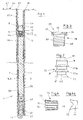
- FIG. 1 shows an anchoring bolt 1 in section.
- the anchoring bolt 1 has a bolt tube 2 with its inner-lying bolt tube bore 3.
- the anchoring bolt 1 has a proximal end at which there is a bolt head 28 and a distal end at which there is a bolt tip 27 are shown.
- the bolt tube 2 is profiled on the outside. This profile 7 is provided to improve the adhesion of the adhesive on the steel wall.
- the inner wall 4 of the bolt tube 2 is not smooth but, as is conventional today, instead has an internal thread 22 which, when the profile 7 is produced on the outer wall, is practically automatically generated with it.
- This internal thread 22 produces indentations 79,80 which render the previously-known extruding pistons unusable.
- the anchoring compound 5, here in the form of a multiple adhesive cartridge arrangement 6, should be squeezed or pressed out effectively from the bolt head 28 in the direction of the deepest part of the borehole by way of this extruding piston 8.
- Part 5a in Figure 5 denotes a second component in an adhesive cartridge 6, which is mixed intensively in the static mixer 61 when the adhesive material is pushed out.
- the extruding piston 8 is reproduced in simplified form, wherein only the insertion end 42 forms a type of hat here.
- a construction of the extruding piston 8 is reproduced more clearly in Figure 2 , wherein a plurality of extruding pistons 8, 8' , 8" are pushed inside one another here for the sake of simplicity.
- a multiple piston arrangement 70 of this type has a plurality of guide and sealing rims 77,77a,77b.
- the extruding piston 8 (only schematically reproduced here) also has a plurality of such guide and sealing rims 77,77a,77b.
- the extruding piston 8 is pressed through along the inner wall 4 of the bolt tube 2 by way of a source of power (not illustrated here), wherein it moves into the bolt tube 2, rotating in some respect and aided by the specially designed guide and sealing rims 77, 77a, 77b.
- a guide element 71 is arranged in front of the extruding piston 8, as shown in Figure 1 .
- This guide element 71 (illustrated in Figure 4 ) is placed with its base 72 on the piston base 12 of the extruding piston 8 and can also expediently be detachably connected thereto.
- This guide element 71 has a plurality of side elements 73, 74 which form a turned-up edge 75 at the end face for scraping inner wall 4 and in order to thus improve the guidance of this guide element 71 for the extruding piston 8.
- the adhesive cartridge 6 with its anchoring compound 5 is held reliably and it is ensured that the adhesive cartridge 6 is moved in the direction of the static mixer 61.
- a plain washer (not shown further here) holds the casing of the adhesive cartridge 6 securely and ensures reliable opening of the entire adhesive cartridge 6, because the washer is pressed down from the lower end of the adhesive cartridge 6.
- the borehole-side end of the bolt tube 2 is denoted by 14 and shows the mixing head constructed there, which ensures that the exiting material of the anchoring compound 5 is pressed reliably into the borehole 44.
- the bolt tube wall 69 does not end with the rock 47 but projects beyond it to then enable the connection of the source of power.
- the rock 47 is secured by the sheathing 46 (which is merely indicated).
- the indentations 79, 80 i.e. the so-called internal thread 22, extend over the entire length of the inner wall 4.
- the seating adapter 29 which is to be seated at the top of the outer edge of the bolt tube wall 69 is advantageously equipped with an external thread 68 to seat it securely on the bolt head 28.
- This external thread 68 advantageously extends over the entire guide part 59 of the seating adaptor 29, wherein the upper edge with the polygonal socket 32 is formed by a support ring 35 onto which a sealing ring 34 is pushed.
- Figure 4a shows a further embodiment of guide element 71, which is likewise possible when using a material which is capable of a limited flexibility.
- the guide element 71 formed as shown in Figure 4a also has the outer edge denoted as turned-up edge 75 here.
- the guide element 71 having the side elements 73, 74, it can likewise guide the discharge piston 8 along the inner wall 4 without the risk of tilting or the like, even with the indentations 79, 80.
- turned-up edge 75 engages indentations 79,80.
- the extruding piston 8 can comprise a support body 9 and a sealing part 10 pushed onto support body 9.
- the support body 9 is made of a material which enables compressed air or an alternative pressure fluid to be applied from the bolt head 28, such that the support body 9 preferably has a thimble-like form, as shown in Figure 5 .
- the support body 9 has an approximately perpendicular annular wall 11 which ends in a piston base 12, which has a projecting edge 15.
- the sealing part 10 is made of a yielding material, particularly rubber, and has a corresponding annular groove 16 such that when the sealing part 10 is pushed onto support body 9 (or vice versa), projecting edge 15 latches into annular groove 16 to fix sealing part 10 on the support body 9.
- Figures 6 to 8 show different embodiments of the sealing part 10, wherein a type of annular bead 19, 20, which is optimally integrated in the respective indentation, is shown in Figures 6 and 7 .
- a plurality of lamellas or flaps 24, 25 are provided, which, as mentioned, serve as guide and support rims 18.
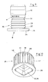
- Figure 10 shows a single-part embodiment of the seating adapter 29
- Figure 9 shows a combined embodiment, wherein the seating adapter 29 is connected to the extruding piston 8 (indicated as 9,10) by way of a predetermined breaking point 31. Therefore, both form a type of tube piece 30, which can be divided by way of the predetermined breaking point 31.
- a sealing ring 34 is pushed onto the support ring 35, whilst, Figure 10 only shows the support ring 35 which has the polygonal socket 32 which here forms a funnel 36.
- the outer wall of the seating adapter 29 has a plurality of longitudinal grooves 37, 38 and spacer webs 39, 40 around it so that a correspondingly formed outer wall 41 is produced.
- the seating adapter 29 shown in Figure 10 is particularly suitable for a smooth inner wall 4, but can also be used with an internal thread 22 under certain circumstances, although the embodiment according to Figure 3 is clearly better for this.
Landscapes
- Engineering & Computer Science (AREA)
- Mining & Mineral Resources (AREA)
- Structural Engineering (AREA)
- Life Sciences & Earth Sciences (AREA)
- General Life Sciences & Earth Sciences (AREA)
- Geochemistry & Mineralogy (AREA)
- Geology (AREA)
- Coating Apparatus (AREA)
- Piles And Underground Anchors (AREA)
- Joining Of Building Structures In Genera (AREA)
- Containers And Packaging Bodies Having A Special Means To Remove Contents (AREA)
- Lining And Supports For Tunnels (AREA)
Description
- The invention relates to an anchoring bolt having an integrated anchoring compound and an extruding piston which acts on this anchoring compound and which, by way of a source of power, may be displaced along the inner wall of the bolt tube, starting from the bolt head and pressing the anchoring compound in the direction of a mixing head associated with the bolt tip.
- Anchoring bolts are rock bolts which primarily serve to stabilise ground formations such as rock in the vicinity of ducts and passages and also tunnels. In the case of a rock bolt or anchoring bolt known from
DE 100 17 750 A1 , a borehole is bored into the ground (such as rock) in a first operating step so that, after the end length has been achieved, a bolt tube having a continuous bolt tube bore can then be introduced into the borehole produced. An anchoring compound, preferably in the form of a multi-chamber adhesive cartridge, is inserted into this bolt tube bore, whereupon the anchoring compound is then pressed into the borehole through a static mixer arranged at the opposite end of the bolt tube by way of an extruding piston. This static mixer is necessary to intensively mix the two components or multiple components of the anchoring compound together so that they then react with one another and harden and thus fix the bolt tube in the borehole so that the rock layers are thereby secured. Serving as the extruding piston inDE 100 17 750 A1 or B4 is a simple plate which is loaded from outside the bolt tube by way of a so-called extruding mechanism so that the plate, pushing the anchoring compound in front of it, is moved through the bolt tube bore. As the figures and the description relating to this known anchoring bolt show, it is assumed here that the bolt tube bore has a smooth wall. Otherwise, it would not be possible to displace the plate loading the anchoring compound without difficulty and, in particular, in sealing manner. However, even with this smooth wall, in the extruding mechanism illustrated therein there is a risk that the extruding piston constructed as a thin disc will cant slightly with the result that adhesive material then escapes past it into the cavity of the bolt tube bore - which cavity should actually be held open - and hinder further actuation of the extruding mechanism. It is moreover disadvantageous and problematic that it is then no longer possible to ensure that the quantity of adhesive mass required for the actual fixing and cementing of the bolt tube is available in the area of operation. However, this problem then becomes substantially greater if the inner wall of the bolt tube is not smooth, as in the construction shown inDE 100 17 750 B4 , but instead profiled. However, this profiling occurs automatically when an outer profile is applied by rollers, as is conventional in bolt tubes of this type. This outer profile presses through onto the inner wall with the result that an extruding piston of this type is not able to carry out its work, or is only able to do so very inadequately. -
US 2006/0153645 A1 discloses a bolt tube in which an adhesive cartridge is arranged and is displaced inside the inner bore of the bolt tube by means of a piston. This piston or extruding mechanism has, on the side wall, bead-like parts for sealing purposes and, at the front, a type of strut by way of which the piston is fixed to the bolt tip so that, after the extrusion of the cartridge, it does not lose its position and, if necessary, continues to seal the bolt tube. This anchoring bolt is disadvantageous in that the extruding mechanism or the extruding piston can only function when the inner wall of the bolt tube bore is smooth. The figures show that the outer surface of the bolt rod or bolt tube is roughened or even provided with slight grooves, although it is clear from the figures, and particularlyFigure 10 , that the inner wall of the inner bore is completely smooth. In a bolt tube which is provided with groove-shaped indentations, an extruding piston of this type would not seal adequately and, in particular, it would not be guided but would either jam, tilt or present other problems. - In principle, the same problems are apparent in an anchoring bolt on the basis of the Provisional Patent Application
ZA2004/10396 US 2006/0153645 A1 , a piston has been used which has no beads or the like opposite the inner wall of the inner bore. Instead, according toFigure 4 , it is provided at both ends with a cap which is arguably intended to assume this sealing function, which it is able to do when the wall is smooth, but not in the construction having the groove-shaped indentations. Even at first glance, it is clear that at least the rear cap will move out of position as soon as the wall is uneven. The front cap will then also lose its function, so that, as a whole, an extruding device of this type is no longer able to fulfill its function. With regard to these two documents relating to the prior art, it should also be noted that an extruding piston of this type is not able to carry out its work, or is only able to do so very inadequately, if the outer profile presses through to the inner wall and therefore even a virtually smooth inner wall is no longer present. - Amelioration of these problems has been sought.
- According to the invention it has been found that where the inner wall of the bolt tube has groove-shaped indentations particularly as a result of the application of the strongly groove-shaped outer profile and where the extruding piston has a support body made of a hard material adapted to the source of power, it is advantageous to provide a sealing part, which is associated with the support body and designed to conform to the inner wall and to promote a "screwing in" of the extruding piston into the bolt tube with the groove-shaped indentations and thereby produce both a sealing and guide function.
- By means of an anchoring bolt of this type, it is for the first time possible - even with a profiled inner wall of the bolt tube - to ensure that the extruding piston used actually presses all of the adhesive material reliably through the static mixer or other mixer into the borehole. Thus, the precisely measured quantity of adhesive is available to fill the cavity between the bolt rod and the borehole wall and thus fix the anchoring bolt or bolt tube effectively in the rock. The extruding piston itself has a sufficiently stable support body, which either absorbs the force of a mechanical plunger and transmits it to the anchoring compound, or which is loaded by hydraulic fluid or compressed air so that it moves reliably along the inner wall of the bolt tube and pushes the anchoring compound in front of it, whereupon the sealing part having a large sealing face always ensures that adhesive does not push past the seal into the cavity located behind it. The large sealing face is produced in that the sealing part forms a sealing face which is sufficient to push all of the adhesive material in the direction of the mixing head by means of the extruding piston. The particular construction of the sealing part here ensures that, even with a pronounced inner profiling, the necessary sealing face by way of which the extruding piston has the continuously even contact pressure against the inner wall is always available. With a profiled inner wall, this sealing face, which is produced or provided by the sealing part, should be, for example, at least somewhat wider than the width of a profile thread. The particular construction of the sealing part results in a screwing-in procedure which ensures that the entire extruding piston is always reliably guided along this rippled inner wall and thereby has a perfect sealing action so that all the adhesive is also pressed effectively into the specified region on the rock or in the rock.
- According to an expedient construction of the invention, it is provided for the extruding piston to be constructed as a tubular piston designed in the shape of a hat, to be introduced into the bolt tube with its piston base pointing towards the adhesive cartridge or anchoring compound and to be formed with its guide and sealing rim, which serves as a sealing part, abutting tightly against the inner wall of the bolt tube with the groove-shaped indentations, sealing against them and guiding the extruding piston. The particular form of the extruding piston ensures that the pressure exerted on it also actually results in the piston moving smoothly along the inner wall of the bolt tube, thereby pressing, as it were, into the groove-shaped indentations and thereby guiding itself and thereby pushing all of the adhesive material in front of it. With this, it exerts such a pressure that the adhesive cartridge opens or is split open on the opposite side so that the adhesive material can exit and move into the static mixer. The description shows that the hat-shaped tubular piston also moves smoothly past the inner wall of the bolt tube because the seal or sealing rim at the same time acts as a guide ring.
- Particularly favourable guidance along the inner wall of the bolt tube is ensured if the extruding piston is constructed in one or more parts. Here, the extruding piston has a length which already substantially prevents canting, wherein this canting is further prevented in that this extruding piston is equipped with the guide means described, relating to the sealing rim.
- The necessary sealing and, at the same time, guidance is then particularly advantageously ensured if the extruding piston has one, two or more guide and sealing rims which are arranged at a spacing from one another and are capable of a limited flexibility. The result of this is that the extruding piston is not only sealed and, at the same time, guided at one point, but instead at several points, wherein it is advantageous if a further guide and sealing rim is present at least at the head of the extruding piston and at the end facing the bolt head. One or more such rims are again advantageously present between these so that an even sealing and guidance is produced overall.
- It was explained above that the extruding piston is pushed or pressed against the adhesive cartridge so that this latter tears open or opens at the end associated with the static mixer in order to release the adhesive in the cartridge. Both to ensure the smooth guidance of the extruding piston and, at the same time, also reliably hold the adhesive cartridge, the invention provides for a guide element with finger-like, resilient side elements to be associated with the extruding piston or multiple piston arrangement and to be integrally formed with its base on the side of the piston base, to be detachably connected thereto or to be present as a single part. This guide element therefore runs in front of the actual extruding piston, receives the end of the adhesive cartridge and thus ensures that the job allocated to it is also carried out optimally. It should be noted here that, at the same time, the sealing effect is thereby also made constant because this guide element ensures that the extruding piston is centred centrally in the bolt tube.
- Since the guide element is intended to have guiding properties, as already shown in the text, it is advantageous if the guide element is designed like a basket and is constructed with resilient side elements which are fixed to its base and have an end-face, outwardly pointing turned-up edge forming a scraper ring. The resilient side elements ensure that the guide element lies practically around the end of the adhesive cartridge and is thereby also centred at the same time, whilst the side elements having the turned-up edge not only ensure this centring but at the same time also ensure that the guide element is also supported on the inner wall of the bolt tube and therefore slides along the inner wall.
- The adhesive material or the anchoring compound comprises a single-chamber or multi-chamber cartridge or else a direct column, so that it is very advantageous if the extruding piston may be adapted to this particular construction of the anchoring compound. This is effected in that the support body is constructed such that it may be equipped with sealing parts of different materials, in particular with regard to their hardness. Here, the sealing part is then virtually pulled over the support body and can therefore be readily exchanged if the conditions of use with regard to the anchoring compound were to change.
- In order to facilitate putting on the sealing part, the invention provides for the support body to be designed like a thimble with an approximately perpendicular annular wall, onto the closed piston base of which a sealing part designed like a hat can be pushed or slipped. This embodiment has the advantage that the sealing part, when pushed through the bolt tube, also deforms automatically so that it can adapt particularly well to the inner wall of the bolt tube. Part of the sealing material can be pushed somewhat away from the piston base, namely as a result of a corresponding load, so that additional sealing beads are produced.
- The multiple support, described above, of the extruding piston against the inner wall can also be achieved in that the sealing part has an outer surface in the region of the annular wall, which outer surface is equipped with lamellas arranged at a spacing. This is advantageous in that, even with short lengths of an extruding piston of this type, it is already possible to achieve even sealing and guidance.
- With relatively coarse threads, it is advantageous if the sealing part has a balloon-like outer surface and/or a deformable coating. Thus, a relatively large mass can push along the inner wall and move into the thread so that, even with complicated inner walls of this type, the necessary sealing action can always be ensured.
- To distribute the adhesive material evenly in the annular channel about the bolt tube, it is advantageous if the support body with its sealing part is constructed such that it may be combined with a seating adapter for a bolt-rotating and extruding device, which seating adapter may be fixed to the bolt head of the bolt tube and projects into the bolt tube, and is preferably detachably connected by way of a predetermined breaking point. This seating adapter enables the necessary connection with the bolt-rotating and extruding device, wherein this should be expediently constructed so that there are no leaks and instead the corresponding pressure force is reliably effected right into the support body of the extruding piston. Whilst the seating adapter then remains on the bolt tube head, the extruding piston moves through the bolt tube in the direction of the mixing head or static mixer. To facilitate assembly, the said predetermined breaking point is advantageous. Thus, both the extruding piston and, at the same time, the seating adapter can be brought into the starting position, wherein the predetermined breaking point yields under an appropriately high pressure so that the seating adapter is then fixed and the support body or the extruding piston can move along the inner wall as described above.
- Irrespective of whether the seating adapter is inserted into the bolt tube with the extruding piston or alone, it is advantageous if it has an outer wall with longitudinal grooves and spacer webs or with an external thread corresponding to the internal thread of the bolt tube. In the latter construction, the seating adapter is rotated practically into the bolt tube, which results in it having a secure seat and, also with the extruding piston arranged in front, ensures that the necessary pressure builds up in the bolt tube for the extruding piston to be pressed against the adhesive cartridge.
- To connect the bolt-rotating and extruding device effectively and tightly to the seating adapter, it is provided for the seating adapter equipped with a square or polygonal socket, an oval or a circular socket to have, at the end facing the bolt head, a support ring which may be combined with a sealing ring and which is dimensioned such that it is supported on the bolt tube wall, wherein the sealing ring is designed such that it may be pushed or clamped onto the support ring. By means of the bolt-rotating and extruding device, the support ring is thus pressed onto the bolt tube wall so that a first sealing action is ensured here. The polygonal or square socket in the seating adapter then acts as a guide and, at the same time, also ensures that the support ring combined with the sealing ring can ensure that the pressure medium, preferably the hydraulic fluid, acts effectively on the extruding piston and ensures that this moves smoothly along the inner wall towards the adhesive cartridge and influences this accordingly. The seating adapter is generally already delivered with a sealing ring pushed onto the support ring, so that it is then ensured that, upon further assembly, this sealing ring also results in the desired successful sealing action. It can also be pushed or clamped on for the first time during the final assembly procedure.
- It is further advantageous if the single- or multi-part extruding piston is designed to form a structural unit with one or more sealing parts and, to this end, is preferably made from elastomers or a resiliently acting material. The extruding piston can then be made available to the respective workman in a complete construction so that it is also ensured that, upon assembly, both parts are then in effective and full working order. This structural unit is then pushed into the bolt tube and acted upon accordingly with pressure or the like so that the extrusion of the adhesive can be carried out evenly and reliably.
- The invention is particularly notable in that, first of all, an extruding piston is produced which is also really worthy of this name. The extruding piston, as a result of the thimble-like construction of the support body or as a result of some other design thereof, is optimally suitable to absorb the applied compressed air or compressed fluid applied and thereby to ensure that it moves smoothly along the inner wall. Moreover, a correspondingly formed support body with a pushed-on sealing part or integrally formed sealing part provides a very advantageously large sealing face, thus ensuring that, upon displacement of the extruding piston along the inner wall of the bolt tube, the adhesive is also effectively and completely pressed out of the bolt tube without the adhesive being able to move along the seal or along the sealing part. This extrusion then proceeds optimally if the inner wall of the bolt tube is profiled, which is almost always the case in today's bolt tubes. It is particularly advantageous here that the extruding piston can be provided with a sealing part constructed according to the conditions, so that an optimally constructed extruding piston can be provided in each case. An extruding piston of this type can be employed both when using adhesive cartridges, preferably multi-chamber cartridges, and with other anchoring compounds, so that, already owing to the versatility of such an extruding piston, considerable advantages over the prior art are evident. In addition to a single extruding piston, it is further advantageous to use a double piston or multiple piston arrangement, especially when each of these individual pistons is provided with a sealing part. These sealing parts, arranged one after another, here ensure both the necessary sealing action and also a smooth guidance of the extruding piston, so that this also moves smoothly when there are corresponding irregularities and when there is an internal thread, and ensures that the adhesive is also actually and exclusively pressed in the direction of the static mixer. For smooth guidance and uniform holding of the adhesive cartridge, a guide element is arranged in front of the actual extruding piston, which guide element has resilient side elements and a turned-up edge so that precise mounting and holding of the adhesive cartridge and smooth guidance along the inner wall of the bolt tube is produced. Together with the extruding piston, a seating adapter is expediently associated with the bolt head or is pushed into the end of the inner bore, wherein this seating adapter ensures an even and secure connection of the bolt-rotating and extruding device and, at the same time, a sealing action in this connecting region.
- Further details and advantages of the inventive subject matter are revealed in the description below of the associated drawing, in which a preferred exemplary embodiment having the details and individual parts necessary for this is illustrated. The drawings show in:
-
Figure 1 shows an anchoring bolt in section, inserted into a borehole with a profiled inner wall; -
Figure 2 shows a multiple piston arrangement, composed of a plurality of individual pistons, in a side view; -
Figure 3 shows a seating adapter with a thread; -
Figure 4 shows a guide element of an extruding piston in a side view with flexible side elements; -
Figure 4a shows a single-part construction of such a guide element; -
Figure 5 shows a section through a bolt tube in the region of the bolt head with a profiled inner wall; -
Figure 5a shows an enlargement in the region of the inserted extruding piston; -
Figure 6 shows a schematic illustration of a support body with a balloon-like sealing part; -
Figure 7 shows a schematic illustration of a support body with a yielding sealing part; -
Figure 8 shows a schematic illustration of a support body with a plurality of lamella-like sealing parts; -
Figure 9 shows a combined seating adapter/extruding piston; and -
Figure 10 shows a seating adapter, reproduced in perspective, with axial longitudinal grooves. -
Figure 1 shows ananchoring bolt 1 in section. Theanchoring bolt 1 has abolt tube 2 with its inner-lying bolt tube bore 3. Theanchoring bolt 1 has a proximal end at which there is abolt head 28 and a distal end at which there is abolt tip 27 are shown. It is made clear that thebolt tube 2 is profiled on the outside. Thisprofile 7 is provided to improve the adhesion of the adhesive on the steel wall. It is moreover clearly shown that theinner wall 4 of thebolt tube 2 is not smooth but, as is conventional today, instead has aninternal thread 22 which, when theprofile 7 is produced on the outer wall, is practically automatically generated with it. Thisinternal thread 22 producesindentations compound 5, here in the form of a multipleadhesive cartridge arrangement 6, should be squeezed or pressed out effectively from thebolt head 28 in the direction of the deepest part of the borehole by way of thisextruding piston 8.Part 5a inFigure 5 denotes a second component in anadhesive cartridge 6, which is mixed intensively in thestatic mixer 61 when the adhesive material is pushed out. - In
Figure 1 , theextruding piston 8 is reproduced in simplified form, wherein only theinsertion end 42 forms a type of hat here. A construction of theextruding piston 8 is reproduced more clearly inFigure 2 , wherein a plurality of extrudingpistons multiple piston arrangement 70 of this type has a plurality of guide and sealingrims - In the illustration according to
Figure 1 , the extruding piston 8 (only schematically reproduced here) also has a plurality of such guide and sealingrims extruding piston 8 is pressed through along theinner wall 4 of thebolt tube 2 by way of a source of power (not illustrated here), wherein it moves into thebolt tube 2, rotating in some respect and aided by the specially designed guide and sealingrims - In addition, it is advantageous if a
guide element 71 is arranged in front of theextruding piston 8, as shown inFigure 1 . This guide element 71 (illustrated inFigure 4 ) is placed with itsbase 72 on thepiston base 12 of theextruding piston 8 and can also expediently be detachably connected thereto. Thisguide element 71 has a plurality ofside elements edge 75 at the end face for scrapinginner wall 4 and in order to thus improve the guidance of thisguide element 71 for theextruding piston 8. At the same time, as shown inFigure 1 , theadhesive cartridge 6 with its anchoringcompound 5 is held reliably and it is ensured that theadhesive cartridge 6 is moved in the direction of thestatic mixer 61. By way of ascreen 62 arranged there, it is ensured that, when theadhesive cartridge 6 is opened, no parts can slip into thestatic mixer 61. A plain washer (not shown further here) holds the casing of theadhesive cartridge 6 securely and ensures reliable opening of the entireadhesive cartridge 6, because the washer is pressed down from the lower end of theadhesive cartridge 6. The borehole-side end of thebolt tube 2 is denoted by 14 and shows the mixing head constructed there, which ensures that the exiting material of the anchoringcompound 5 is pressed reliably into the borehole 44. - It is shown at the
bolt head 28 that thebolt tube wall 69 does not end with therock 47 but projects beyond it to then enable the connection of the source of power. Therock 47 is secured by the sheathing 46 (which is merely indicated). - It is furthermore shown in
Figure 1 that theindentations internal thread 22, extend over the entire length of theinner wall 4. This means that theseating adapter 29 which is to be seated at the top of the outer edge of thebolt tube wall 69 is advantageously equipped with anexternal thread 68 to seat it securely on thebolt head 28. Thisexternal thread 68 advantageously extends over the entire guide part 59 of theseating adaptor 29, wherein the upper edge with thepolygonal socket 32 is formed by asupport ring 35 onto which asealing ring 34 is pushed. - Reference has already been made to
Figure 4. Figure 4a shows a further embodiment ofguide element 71, which is likewise possible when using a material which is capable of a limited flexibility. Theguide element 71 formed as shown inFigure 4a also has the outer edge denoted as turned-upedge 75 here. As in the embodiment according toFigure 4 with theguide element 71 having theside elements discharge piston 8 along theinner wall 4 without the risk of tilting or the like, even with theindentations edge 75 engagesindentations - In the embodiment according to
Figure 5 , it is likewise shown that theextruding piston 8 can comprise asupport body 9 and a sealingpart 10 pushed ontosupport body 9. Thesupport body 9 is made of a material which enables compressed air or an alternative pressure fluid to be applied from thebolt head 28, such that thesupport body 9 preferably has a thimble-like form, as shown inFigure 5 . Accordingly as shown inFigure 5a , thesupport body 9 has an approximately perpendicularannular wall 11 which ends in apiston base 12, which has a projectingedge 15. The sealingpart 10 is made of a yielding material, particularly rubber, and has a correspondingannular groove 16 such that when the sealingpart 10 is pushed onto support body 9 (or vice versa), projectingedge 15 latches intoannular groove 16 to fix sealingpart 10 on thesupport body 9. - The perpendicular
annular wall 11 ofsupport body 9 ofpiston 8 merges into a guide andsupport edge 18 at itsopen end 17. Guide andsupport edge 18 produces a sealingface 13 which ensures effective sealing of theextruding piston 8 against theinner wall 4 of thebolt tube 2. The guide andsupport edge 18 prevents the sealingpart 10 from becoming thinner or being pulled correspondingly long, as it were, upon insertion. Instead, a compression is effected here at the guide andsupport edge 18 so that this still ensures the optimisation of the sealingface 13 which lies tightly against theinner wall 4 of thebolt tube 2.Figure 5a shows that theouter surface 23 of the sealingpart 10 is deformed such that it moves fully into the indentation and thus ensures a reliable and trouble-free pressing out of the anchoringcompound 5. -
Figures 6 to 8 show different embodiments of the sealingpart 10, wherein a type ofannular bead Figures 6 and 7 . According toFigure 8 , a plurality of lamellas or flaps 24, 25 are provided, which, as mentioned, serve as guide and support rims 18. - Whilst
Figure 10 shows a single-part embodiment of theseating adapter 29,Figure 9 shows a combined embodiment, wherein theseating adapter 29 is connected to the extruding piston 8 (indicated as 9,10) by way of apredetermined breaking point 31. Therefore, both form a type oftube piece 30, which can be divided by way of thepredetermined breaking point 31. A sealingring 34 is pushed onto thesupport ring 35, whilst,Figure 10 only shows thesupport ring 35 which has thepolygonal socket 32 which here forms a funnel 36. According toFigure 10 , the outer wall of theseating adapter 29 has a plurality oflongitudinal grooves spacer webs outer wall 41 is produced. Theseating adapter 29 shown inFigure 10 is particularly suitable for a smoothinner wall 4, but can also be used with aninternal thread 22 under certain circumstances, although the embodiment according toFigure 3 is clearly better for this. - All the said features, including those which are revealed in the drawings alone, are to be seen as inventive in their own right and in combination.
Claims (15)
- An anchoring bolt (1) comprising:a bolt tube (2) having an inner wall (4) which forms one or more indentations (79,80); and characterised in that the anchoring bolt (1) further comprises:an extruding piston (8) which has a sealing part (10) to engage the one or more indentations (79,80) to:- seal the extruding piston (8) against the inner wall (4); or to- seal the extruding piston (8) against the inner wall (4) and to guide movement of the extruding piston (8) through the bolt tube (2).
- An anchoring bolt (1) comprising:a bolt tube (2) having an inner wall (4) which forms more than one indentation (79,80); and characterised by:an extruding piston (8) which has a sealing part (10) to engage the more than one indentation (79,80) to guide movement of the extruding piston (8) through the bolt tube (2).
- An anchoring bolt as defined in any one of the preceding claims wherein the extruding piston (8) has a tubular shape in the form of a receptacle, preferably the extruding piston (8) is formed a receptacle shaped sealing part which receives a receptacle shaped support body, preferably the support body resiliently engages the sealing part (10)
- An anchoring bolt (1) as defined in any one of the preceding claims wherein the extruding piston (8) has one or more guide and/or sealing rims for engaging the one or more indentations (79,80), preferably the one or more guide and/or sealing rims are spaced from one another and are capable of a limited flexibility.
- An anchoring bolt (1) as defined in any one of the preceding claims wherein the extruding piston (8) has a guide element (71) for engaging the adhesive compound, preferably the guide element (71) is detachably connected or is fixed to the extruding piston (8).
- An anchoring bolt (1) as defined in claim 5 wherein the guide element (71) has one or more resilient elements for scraping adhesive compound from the inner wall (4).
- An anchoring bolt (1) as defined in any one of the preceding claims wherein the sealing part has a balloon-like outer surface and/or a deformable coating.
- An anchoring bolt (1) as defined in any one of the preceding claims which comprises a seating adaptor (29) for engagement with a bolt-rotation device wherein the extruding piston (8) is detachably combined with the seating adapter (29), preferably the extruding piston (8) is detachably connected by a link that breaks at a predetermined pressure.
- An anchoring bolt (1) as defined in claim 8 wherein the seating adapter (29) has an outer wall with one or more formations for engaging with the one or more indentations (79, 80).
- An anchoring (1) bolt as defined in claim 8 or claim 9 wherein the seating adapter (29) equipped with a square or polygonal socket (32), an oval or a circular socket has, at the end (33) facing the bolt head (28), a support ring (35) which may be combined with a sealing ring (34) and which is dimensioned such that it is supported on the bolt tube wall (69), wherein the sealing ring (34) is designed such that it may be pushed or clamped onto the support ring (35).
- An anchoring bolt (1) as defined in any one of the preceding claims wherein the extruding piston (8) is formed from a resilient material, preferably the extruding piston (8) is formed from an elastomer.
- An anchoring bolt (1) as defined in any one of the preceding claims which has a distal end which, in use, is anchored in a borehole wherein from the distal end of the bolt tube, there is placed the anchoring compound, the guide element, and the extruding piston and wherein the seating adaptor is placed on a proximal end of the anchoring bolt.
- A method of anchoring an anchoring bolt (1) in a borehole which method comprises the steps of:forming an anchoring bolt (1) with a bolt tube (2) having an inner wall (4);forming one or more indentations (79,80) on the inner wall (4);placing in the bolt tube (2) an adhesive compound suitable for anchoring the bolt (1) in the borehole;arranging an extruding piston (8) in the bolt tube (2) adjacent the adhesive compound wherein the extruding piston (8) has a sealing part (10) to engage the one or more indentations (79, 80) to:- seal the extruding piston (8) against the inner wall (4); or to- seal the extruding piston (8) against the inner wall (4) and to guide movement of the extruding piston (8) through the bolt tube (2);placing the anchoring bolt (1) in a borehole;applying pressure to the extruding piston (8) such that the extruding piston (8) forces the adhesive compound out of the bolt tube (2) to anchor the anchoring bolt (1) in the borehole.
- A method of anchoring an anchoring bolt (1) in a borehole which method comprises the steps of:forming an anchoring bolt (1) with a bolt tube (2) having an inner wall (4);forming more than one indentation (79, 80) on the inner wall (4);placing in the bolt tube (2) an adhesive compound suitable for anchoring the bolt (1) in the borehole;arranging an extruding piston (8) in the bolt tube (2) adjacent the adhesive compound wherein the extruding piston (8) has a sealing part to engage the more than one indentation (79, 80) to guide movement of the extruding piston (8) through the bolt tube (2);placing the anchoring bolt (1) in a borehole;applying pressure to the extruding piston (8) such that the extruding piston (8) forces the adhesive compound out of the bolt tube (2) to anchor the anchoring bolt (1) in the borehole.
- A method as defined in claims 13 or 14 wherein the step of forming the one or more indentations (79, 80) comprises applying an outer profile on the anchoring bolt (1).
Priority Applications (1)
| Application Number | Priority Date | Filing Date | Title |
|---|---|---|---|
| PL10731783T PL2438270T3 (en) | 2009-06-04 | 2010-06-04 | Anchoring bolt having an extruding piston |
Applications Claiming Priority (3)
| Application Number | Priority Date | Filing Date | Title |
|---|---|---|---|
| DE102009023886 | 2009-06-04 | ||
| DE102010009106A DE102010009106A1 (en) | 2009-06-04 | 2010-02-24 | Adhesive with integrated gluing column and displaceable piston in the anchor tube |
| PCT/GB2010/050945 WO2010140006A2 (en) | 2009-06-04 | 2010-06-04 | Nchoring bolt having an extruding piston |
Publications (2)
| Publication Number | Publication Date |
|---|---|
| EP2438270A2 EP2438270A2 (en) | 2012-04-11 |
| EP2438270B1 true EP2438270B1 (en) | 2014-03-26 |
Family
ID=43049439
Family Applications (1)
| Application Number | Title | Priority Date | Filing Date |
|---|---|---|---|
| EP10731783.6A Not-in-force EP2438270B1 (en) | 2009-06-04 | 2010-06-04 | Anchoring bolt having an extruding piston |
Country Status (7)
| Country | Link |
|---|---|
| EP (1) | EP2438270B1 (en) |
| CN (1) | CN102803654B (en) |
| AU (1) | AU2010255501B2 (en) |
| CL (1) | CL2011003061A1 (en) |
| DE (1) | DE102010009106A1 (en) |
| PL (1) | PL2438270T3 (en) |
| WO (1) | WO2010140006A2 (en) |
Families Citing this family (3)
| Publication number | Priority date | Publication date | Assignee | Title |
|---|---|---|---|---|
| DE102011086614A1 (en) | 2011-11-18 | 2013-05-23 | Hilti Aktiengesellschaft | rock bolt |
| CN110030025B (en) * | 2019-05-17 | 2024-01-30 | 东北大学 | Self-expansion type pipe joint anchor rod for surrounding rock large deformation and preparation and use methods thereof |
| CN113187533B (en) * | 2021-05-10 | 2023-05-09 | 南通理工学院 | Large-stroke recyclable hydraulic yielding anchor rod |
Family Cites Families (6)
| Publication number | Priority date | Publication date | Assignee | Title |
|---|---|---|---|---|
| DE19631039A1 (en) * | 1996-08-01 | 1998-02-05 | Reburg Patentverwertungs Gmbh | Method of placing rockbolt via medium=filled cavity and drillrod |
| JPH10169394A (en) * | 1996-12-12 | 1998-06-23 | Tokyu Constr Co Ltd | Fixing method of lock bolt and end cap |
| DE10017763B4 (en) * | 2000-04-10 | 2008-11-20 | Hilti Aktiengesellschaft | rock bolts |
| DE10017750B4 (en) | 2000-04-10 | 2008-11-20 | Hilti Aktiengesellschaft | rock bolts |
| CA2530323C (en) | 2004-12-20 | 2013-01-29 | Dywidag-Systems International Pty Limited | Rock bolt |
| AU2007203613A1 (en) * | 2006-08-02 | 2008-02-21 | Minova Australia Pty Limited | Resin Cartridge Insertion Method & Apparatus |
-
2010
- 2010-02-24 DE DE102010009106A patent/DE102010009106A1/en not_active Withdrawn
- 2010-06-04 EP EP10731783.6A patent/EP2438270B1/en not_active Not-in-force
- 2010-06-04 WO PCT/GB2010/050945 patent/WO2010140006A2/en not_active Ceased
- 2010-06-04 CN CN201080024853.9A patent/CN102803654B/en not_active Expired - Fee Related
- 2010-06-04 AU AU2010255501A patent/AU2010255501B2/en not_active Ceased
- 2010-06-04 PL PL10731783T patent/PL2438270T3/en unknown
-
2011
- 2011-12-02 CL CL2011003061A patent/CL2011003061A1/en unknown
Also Published As
| Publication number | Publication date |
|---|---|
| PL2438270T3 (en) | 2014-07-31 |
| AU2010255501A1 (en) | 2011-12-22 |
| EP2438270A2 (en) | 2012-04-11 |
| WO2010140006A3 (en) | 2011-05-12 |
| AU2010255501B2 (en) | 2016-05-19 |
| AU2010255501A8 (en) | 2015-08-27 |
| WO2010140006A2 (en) | 2010-12-09 |
| CN102803654A (en) | 2012-11-28 |
| CN102803654B (en) | 2015-11-25 |
| DE102010009106A1 (en) | 2010-12-09 |
| CL2011003061A1 (en) | 2012-08-31 |
Similar Documents
| Publication | Publication Date | Title |
|---|---|---|
| JP4904314B2 (en) | tool | |
| US4907727A (en) | Dispensing device having improved plunger assemblies | |
| CA2342507C (en) | Tubular anchor(iii) | |
| KR100292590B1 (en) | Sealant Cartridge | |
| CN101378977B (en) | distribute instruments | |
| JP5385074B2 (en) | Drug infusion tool | |
| US7909338B2 (en) | Adapter member of a rock anchor | |
| AU2010255501B2 (en) | Anchoring bolt having an extruding piston | |
| US8250828B2 (en) | Anchor with cement contour | |
| US4430025A (en) | Oblate friction rock stabilizer and installation lubricating cement utilized therewith | |
| JPH0913511A (en) | Back cut anchor locking method | |
| KR200477094Y1 (en) | A silicon gun | |
| CA3007274C (en) | System and method for reducing air ingression into sealant tubes | |
| US7779908B2 (en) | Arrangement for affixing an expandable packer in a hole | |
| US7789589B2 (en) | Fastening element | |
| US7284932B2 (en) | Pressing-out apparatus | |
| US20230392500A1 (en) | Hollow rod shear connector having static mixing system and method for setting a hollow rod shear connector in a rock layer | |
| AU2005201664A1 (en) | Fastening element | |
| KR102654099B1 (en) | Extrusion type Putty Cartridge | |
| US7784648B2 (en) | Press-out tool | |
| JP5702935B2 (en) | Discharge device for filling material and method for filling the same | |
| KR200373321Y1 (en) | Silicon injectiing gun | |
| CN119288374B (en) | A mud blowout preventer box for pressure working equipment | |
| JP7372625B2 (en) | Water faucet tight core installation tool | |
| KR200305695Y1 (en) | Instilling device for cavity formed on the wall of tunnel |
Legal Events
| Date | Code | Title | Description |
|---|---|---|---|
| PUAI | Public reference made under article 153(3) epc to a published international application that has entered the european phase |
Free format text: ORIGINAL CODE: 0009012 |
|
| 17P | Request for examination filed |
Effective date: 20111219 |
|
| AK | Designated contracting states |
Kind code of ref document: A2 Designated state(s): AL AT BE BG CH CY CZ DE DK EE ES FI FR GB GR HR HU IE IS IT LI LT LU LV MC MK MT NL NO PL PT RO SE SI SK SM TR |
|
| DAX | Request for extension of the european patent (deleted) | ||
| 17Q | First examination report despatched |
Effective date: 20130205 |
|
| GRAP | Despatch of communication of intention to grant a patent |
Free format text: ORIGINAL CODE: EPIDOSNIGR1 |
|
| INTG | Intention to grant announced |
Effective date: 20131004 |
|
| GRAS | Grant fee paid |
Free format text: ORIGINAL CODE: EPIDOSNIGR3 |
|
| GRAA | (expected) grant |
Free format text: ORIGINAL CODE: 0009210 |
|
| AK | Designated contracting states |
Kind code of ref document: B1 Designated state(s): AL AT BE BG CH CY CZ DE DK EE ES FI FR GB GR HR HU IE IS IT LI LT LU LV MC MK MT NL NO PL PT RO SE SI SK SM TR |
|
| REG | Reference to a national code |
Ref country code: GB Ref legal event code: FG4D |
|
| REG | Reference to a national code |
Ref country code: CH Ref legal event code: EP |
|
| REG | Reference to a national code |
Ref country code: AT Ref legal event code: REF Ref document number: 659128 Country of ref document: AT Kind code of ref document: T Effective date: 20140415 |
|
| REG | Reference to a national code |
Ref country code: IE Ref legal event code: FG4D |
|
| REG | Reference to a national code |
Ref country code: DE Ref legal event code: R096 Ref document number: 602010014622 Country of ref document: DE Effective date: 20140515 |
|
| REG | Reference to a national code |
Ref country code: SE Ref legal event code: TRGR |
|
| PG25 | Lapsed in a contracting state [announced via postgrant information from national office to epo] |
Ref country code: NO Free format text: LAPSE BECAUSE OF FAILURE TO SUBMIT A TRANSLATION OF THE DESCRIPTION OR TO PAY THE FEE WITHIN THE PRESCRIBED TIME-LIMIT Effective date: 20140626 Ref country code: LT Free format text: LAPSE BECAUSE OF FAILURE TO SUBMIT A TRANSLATION OF THE DESCRIPTION OR TO PAY THE FEE WITHIN THE PRESCRIBED TIME-LIMIT Effective date: 20140326 |
|
| REG | Reference to a national code |
Ref country code: PL Ref legal event code: T3 |
|
| REG | Reference to a national code |
Ref country code: AT Ref legal event code: MK05 Ref document number: 659128 Country of ref document: AT Kind code of ref document: T Effective date: 20140326 |
|
| REG | Reference to a national code |
Ref country code: NL Ref legal event code: VDEP Effective date: 20140326 |
|
| REG | Reference to a national code |
Ref country code: LT Ref legal event code: MG4D |
|
| PG25 | Lapsed in a contracting state [announced via postgrant information from national office to epo] |
Ref country code: LV Free format text: LAPSE BECAUSE OF FAILURE TO SUBMIT A TRANSLATION OF THE DESCRIPTION OR TO PAY THE FEE WITHIN THE PRESCRIBED TIME-LIMIT Effective date: 20140326 Ref country code: HR Free format text: LAPSE BECAUSE OF FAILURE TO SUBMIT A TRANSLATION OF THE DESCRIPTION OR TO PAY THE FEE WITHIN THE PRESCRIBED TIME-LIMIT Effective date: 20140326 |
|
| PG25 | Lapsed in a contracting state [announced via postgrant information from national office to epo] |
Ref country code: RO Free format text: LAPSE BECAUSE OF FAILURE TO SUBMIT A TRANSLATION OF THE DESCRIPTION OR TO PAY THE FEE WITHIN THE PRESCRIBED TIME-LIMIT Effective date: 20140326 Ref country code: EE Free format text: LAPSE BECAUSE OF FAILURE TO SUBMIT A TRANSLATION OF THE DESCRIPTION OR TO PAY THE FEE WITHIN THE PRESCRIBED TIME-LIMIT Effective date: 20140326 Ref country code: NL Free format text: LAPSE BECAUSE OF FAILURE TO SUBMIT A TRANSLATION OF THE DESCRIPTION OR TO PAY THE FEE WITHIN THE PRESCRIBED TIME-LIMIT Effective date: 20140326 Ref country code: CY Free format text: LAPSE BECAUSE OF FAILURE TO SUBMIT A TRANSLATION OF THE DESCRIPTION OR TO PAY THE FEE WITHIN THE PRESCRIBED TIME-LIMIT Effective date: 20140326 Ref country code: BE Free format text: LAPSE BECAUSE OF FAILURE TO SUBMIT A TRANSLATION OF THE DESCRIPTION OR TO PAY THE FEE WITHIN THE PRESCRIBED TIME-LIMIT Effective date: 20140326 Ref country code: IS Free format text: LAPSE BECAUSE OF FAILURE TO SUBMIT A TRANSLATION OF THE DESCRIPTION OR TO PAY THE FEE WITHIN THE PRESCRIBED TIME-LIMIT Effective date: 20140726 |
|
| PG25 | Lapsed in a contracting state [announced via postgrant information from national office to epo] |
Ref country code: AT Free format text: LAPSE BECAUSE OF FAILURE TO SUBMIT A TRANSLATION OF THE DESCRIPTION OR TO PAY THE FEE WITHIN THE PRESCRIBED TIME-LIMIT Effective date: 20140326 Ref country code: SK Free format text: LAPSE BECAUSE OF FAILURE TO SUBMIT A TRANSLATION OF THE DESCRIPTION OR TO PAY THE FEE WITHIN THE PRESCRIBED TIME-LIMIT Effective date: 20140326 Ref country code: ES Free format text: LAPSE BECAUSE OF FAILURE TO SUBMIT A TRANSLATION OF THE DESCRIPTION OR TO PAY THE FEE WITHIN THE PRESCRIBED TIME-LIMIT Effective date: 20140326 |
|
| PG25 | Lapsed in a contracting state [announced via postgrant information from national office to epo] |
Ref country code: PT Free format text: LAPSE BECAUSE OF FAILURE TO SUBMIT A TRANSLATION OF THE DESCRIPTION OR TO PAY THE FEE WITHIN THE PRESCRIBED TIME-LIMIT Effective date: 20140728 |
|
| REG | Reference to a national code |
Ref country code: DE Ref legal event code: R097 Ref document number: 602010014622 Country of ref document: DE |
|
| PG25 | Lapsed in a contracting state [announced via postgrant information from national office to epo] |
Ref country code: MC Free format text: LAPSE BECAUSE OF FAILURE TO SUBMIT A TRANSLATION OF THE DESCRIPTION OR TO PAY THE FEE WITHIN THE PRESCRIBED TIME-LIMIT Effective date: 20140326 Ref country code: LU Free format text: LAPSE BECAUSE OF FAILURE TO SUBMIT A TRANSLATION OF THE DESCRIPTION OR TO PAY THE FEE WITHIN THE PRESCRIBED TIME-LIMIT Effective date: 20140604 Ref country code: DK Free format text: LAPSE BECAUSE OF FAILURE TO SUBMIT A TRANSLATION OF THE DESCRIPTION OR TO PAY THE FEE WITHIN THE PRESCRIBED TIME-LIMIT Effective date: 20140326 |
|
| PLBE | No opposition filed within time limit |
Free format text: ORIGINAL CODE: 0009261 |
|
| REG | Reference to a national code |
Ref country code: CH Ref legal event code: PL |
|
| STAA | Information on the status of an ep patent application or granted ep patent |
Free format text: STATUS: NO OPPOSITION FILED WITHIN TIME LIMIT |
|
| 26N | No opposition filed |
Effective date: 20150106 |
|
| REG | Reference to a national code |
Ref country code: IE Ref legal event code: MM4A |
|
| REG | Reference to a national code |
Ref country code: FR Ref legal event code: ST Effective date: 20150227 |
|
| PG25 | Lapsed in a contracting state [announced via postgrant information from national office to epo] |
Ref country code: IT Free format text: LAPSE BECAUSE OF FAILURE TO SUBMIT A TRANSLATION OF THE DESCRIPTION OR TO PAY THE FEE WITHIN THE PRESCRIBED TIME-LIMIT Effective date: 20140326 |
|
| REG | Reference to a national code |
Ref country code: DE Ref legal event code: R097 Ref document number: 602010014622 Country of ref document: DE Effective date: 20150106 |
|
| PG25 | Lapsed in a contracting state [announced via postgrant information from national office to epo] |
Ref country code: LI Free format text: LAPSE BECAUSE OF NON-PAYMENT OF DUE FEES Effective date: 20140630 Ref country code: IE Free format text: LAPSE BECAUSE OF NON-PAYMENT OF DUE FEES Effective date: 20140604 Ref country code: CH Free format text: LAPSE BECAUSE OF NON-PAYMENT OF DUE FEES Effective date: 20140630 |
|
| PG25 | Lapsed in a contracting state [announced via postgrant information from national office to epo] |
Ref country code: FR Free format text: LAPSE BECAUSE OF NON-PAYMENT OF DUE FEES Effective date: 20140630 |
|
| PG25 | Lapsed in a contracting state [announced via postgrant information from national office to epo] |
Ref country code: SI Free format text: LAPSE BECAUSE OF FAILURE TO SUBMIT A TRANSLATION OF THE DESCRIPTION OR TO PAY THE FEE WITHIN THE PRESCRIBED TIME-LIMIT Effective date: 20140326 |
|
| PG25 | Lapsed in a contracting state [announced via postgrant information from national office to epo] |
Ref country code: MT Free format text: LAPSE BECAUSE OF FAILURE TO SUBMIT A TRANSLATION OF THE DESCRIPTION OR TO PAY THE FEE WITHIN THE PRESCRIBED TIME-LIMIT Effective date: 20140326 |
|
| PG25 | Lapsed in a contracting state [announced via postgrant information from national office to epo] |
Ref country code: SM Free format text: LAPSE BECAUSE OF FAILURE TO SUBMIT A TRANSLATION OF THE DESCRIPTION OR TO PAY THE FEE WITHIN THE PRESCRIBED TIME-LIMIT Effective date: 20140326 |
|
| PG25 | Lapsed in a contracting state [announced via postgrant information from national office to epo] |
Ref country code: GR Free format text: LAPSE BECAUSE OF FAILURE TO SUBMIT A TRANSLATION OF THE DESCRIPTION OR TO PAY THE FEE WITHIN THE PRESCRIBED TIME-LIMIT Effective date: 20140627 |
|
| PG25 | Lapsed in a contracting state [announced via postgrant information from national office to epo] |
Ref country code: HU Free format text: LAPSE BECAUSE OF FAILURE TO SUBMIT A TRANSLATION OF THE DESCRIPTION OR TO PAY THE FEE WITHIN THE PRESCRIBED TIME-LIMIT; INVALID AB INITIO Effective date: 20100604 |
|
| PGFP | Annual fee paid to national office [announced via postgrant information from national office to epo] |
Ref country code: GB Payment date: 20170531 Year of fee payment: 8 Ref country code: DE Payment date: 20170530 Year of fee payment: 8 Ref country code: CZ Payment date: 20170524 Year of fee payment: 8 |
|
| PGFP | Annual fee paid to national office [announced via postgrant information from national office to epo] |
Ref country code: SE Payment date: 20170613 Year of fee payment: 8 Ref country code: BG Payment date: 20170531 Year of fee payment: 8 Ref country code: FI Payment date: 20170609 Year of fee payment: 8 Ref country code: PL Payment date: 20170531 Year of fee payment: 8 |
|
| PGFP | Annual fee paid to national office [announced via postgrant information from national office to epo] |
Ref country code: TR Payment date: 20170601 Year of fee payment: 8 |
|
| PG25 | Lapsed in a contracting state [announced via postgrant information from national office to epo] |
Ref country code: MK Free format text: LAPSE BECAUSE OF FAILURE TO SUBMIT A TRANSLATION OF THE DESCRIPTION OR TO PAY THE FEE WITHIN THE PRESCRIBED TIME-LIMIT Effective date: 20140326 |
|
| PG25 | Lapsed in a contracting state [announced via postgrant information from national office to epo] |
Ref country code: AL Free format text: LAPSE BECAUSE OF FAILURE TO SUBMIT A TRANSLATION OF THE DESCRIPTION OR TO PAY THE FEE WITHIN THE PRESCRIBED TIME-LIMIT Effective date: 20140326 |
|
| REG | Reference to a national code |
Ref country code: DE Ref legal event code: R119 Ref document number: 602010014622 Country of ref document: DE |
|
| REG | Reference to a national code |
Ref country code: SE Ref legal event code: EUG |
|
| PG25 | Lapsed in a contracting state [announced via postgrant information from national office to epo] |
Ref country code: FI Free format text: LAPSE BECAUSE OF NON-PAYMENT OF DUE FEES Effective date: 20180604 Ref country code: SE Free format text: LAPSE BECAUSE OF NON-PAYMENT OF DUE FEES Effective date: 20180605 Ref country code: CZ Free format text: LAPSE BECAUSE OF NON-PAYMENT OF DUE FEES Effective date: 20180604 |
|
| GBPC | Gb: european patent ceased through non-payment of renewal fee |
Effective date: 20180604 |
|
| PG25 | Lapsed in a contracting state [announced via postgrant information from national office to epo] |
Ref country code: DE Free format text: LAPSE BECAUSE OF NON-PAYMENT OF DUE FEES Effective date: 20190101 Ref country code: GB Free format text: LAPSE BECAUSE OF NON-PAYMENT OF DUE FEES Effective date: 20180604 |
|
| PG25 | Lapsed in a contracting state [announced via postgrant information from national office to epo] |
Ref country code: BG Free format text: LAPSE BECAUSE OF NON-PAYMENT OF DUE FEES Effective date: 20190430 |
|
| PG25 | Lapsed in a contracting state [announced via postgrant information from national office to epo] |
Ref country code: PL Free format text: LAPSE BECAUSE OF NON-PAYMENT OF DUE FEES Effective date: 20180604 |
|
| PG25 | Lapsed in a contracting state [announced via postgrant information from national office to epo] |
Ref country code: TR Free format text: LAPSE BECAUSE OF NON-PAYMENT OF DUE FEES Effective date: 20180604 |