EP2437979B1 - Rotor damper and tail rotor with such a rotor damper - Google Patents
Rotor damper and tail rotor with such a rotor damper Download PDFInfo
- Publication number
- EP2437979B1 EP2437979B1 EP09845603.1A EP09845603A EP2437979B1 EP 2437979 B1 EP2437979 B1 EP 2437979B1 EP 09845603 A EP09845603 A EP 09845603A EP 2437979 B1 EP2437979 B1 EP 2437979B1
- Authority
- EP
- European Patent Office
- Prior art keywords
- rotor
- damper
- drive shaft
- hub
- main body
- Prior art date
- Legal status (The legal status is an assumption and is not a legal conclusion. Google has not performed a legal analysis and makes no representation as to the accuracy of the status listed.)
- Active
Links
Images


Classifications
-
- B—PERFORMING OPERATIONS; TRANSPORTING
- B64—AIRCRAFT; AVIATION; COSMONAUTICS
- B64C—AEROPLANES; HELICOPTERS
- B64C27/00—Rotorcraft; Rotors peculiar thereto
- B64C27/82—Rotorcraft; Rotors peculiar thereto characterised by the provision of an auxiliary rotor or fluid-jet device for counter-balancing lifting rotor torque or changing direction of rotorcraft
-
- B—PERFORMING OPERATIONS; TRANSPORTING
- B64—AIRCRAFT; AVIATION; COSMONAUTICS
- B64C—AEROPLANES; HELICOPTERS
- B64C27/00—Rotorcraft; Rotors peculiar thereto
- B64C27/51—Damping of blade movements
-
- B—PERFORMING OPERATIONS; TRANSPORTING
- B64—AIRCRAFT; AVIATION; COSMONAUTICS
- B64C—AEROPLANES; HELICOPTERS
- B64C27/00—Rotorcraft; Rotors peculiar thereto
- B64C27/001—Vibration damping devices
- B64C2027/003—Vibration damping devices mounted on rotor hub, e.g. a rotary force generator
-
- Y—GENERAL TAGGING OF NEW TECHNOLOGICAL DEVELOPMENTS; GENERAL TAGGING OF CROSS-SECTIONAL TECHNOLOGIES SPANNING OVER SEVERAL SECTIONS OF THE IPC; TECHNICAL SUBJECTS COVERED BY FORMER USPC CROSS-REFERENCE ART COLLECTIONS [XRACs] AND DIGESTS
- Y10—TECHNICAL SUBJECTS COVERED BY FORMER USPC
- Y10S—TECHNICAL SUBJECTS COVERED BY FORMER USPC CROSS-REFERENCE ART COLLECTIONS [XRACs] AND DIGESTS
- Y10S416/00—Fluid reaction surfaces, i.e. impellers
- Y10S416/50—Vibration damping features
Definitions
- the present invention relates to a rotor damper for tail rotors of helicopters, according to the preamble of claim 1 and a tail rotor provided with such a rotor damper according to the preamble of claim 9.
- a common type of helicopter is provided with a main rotor and a tail rotor.
- the main rotor supplies the primary forces for flight of the helicopter and the tail rotor provides stability and influence on the flight direction of the helicopter.
- the tail rotor of the helicopter is sensitive for wind disturbances which affects the manoeuvrability of the helicopter. These wind disturbances also creates undesirable vibrations which may be transmitted to the fuselage of the helicopter.
- oscillations of the tail rotor blades are a primary source of undesirable vibrations. Such oscillations may occur from the so-called "scissors mode" motions of the rotor blades in relation to each others. In this mode the blades oscillates relative to the drive shaft and to each others in the plane of rotation of the rotor blades.
- the oscillations and vibrations generated by the tail rotor are undesirable because they increase the mechanical stress of the components in the helicopter.
- Document US-A-3999887 discloses a connecting assembly for the tail rotor of a helicopter.
- the assembly is provided with flexible straps which interconnect the rotor blades with the connecting assembly.
- the connecting assembly is also provided with layers of a viscoelastic material which are disposed normal to the axis of rotation of the drive shaft. By proper selection of the vis-coelastic material for the layers oscillations and vibrations can be reduced through the damping characteristics of the viscoelastic material.
- the layers of viscoelastic material are bound to support or cover plates in the connecting assembly. Bolts and nuts lock the cover plates in a fixed position relative to the drive shaft.
- the objective problem to be solved by the present invention is to increase the manoeuvrability of a helicopter.
- Another objective problem to be solved by the present invention is to achieve a rotor damper which effectively dampens oscillations and vibrations of a tail rotor of a helicopter.
- a further objective problem to be solved by the present invention is to achieve a rotor damper which is easy to replace and which can be replaced in a short period of time.
- a still further objective problem to be solved by the present invention is to easy and in a short period of time change the damping characteristics of a rotor damper.
- a still further objective problem to be solved by the present invention is to achieve a rotor damper for a tail rotor, which is adapted to an unattended helicopter.
- Such a rotor damper effectively dampens oscillations and vibrations of a tail rotor of a helicopter.
- the resilient material in the main body and the flange of the rotor damper will dampen the oscillations and vibrations which emanate from the rotor blades and prevent the oscillations and vibrations from propagate to the drive shaft and further to the helicopter.
- the resilient connection between the hub and the drive shaft also increase the manoeuvrability of the helicopter.
- the rotor damper prevents jerks and high acceleration forces which may occur in connection with a quick changing in the pitch.
- two slits are arranged in the main body, which slits extends in the direction of the length axis.
- the slits in the main body of the rotor damper thus make it possible for the rotor damper to slide into the intended position in the hub and onto the end part of the drive shaft.
- the slits also make it possible to replace the rotor damper with another rotor damper having different damping characteristics.
- the rotor damper is fixated to the drive shaft and in the first bore of the hub by a treaded bolt which is threaded into a threaded hole in an end surface of the free end part of the drive shaft. This makes it easy and in a short period of time change the damping characteristics of a rotor damper.
- a support washer is arranged at an outer surface of the flange of the rotor damper and fixated by the treaded bolt. At least one distance washer is arranged between the support washer and the outer surface of the flange. The effect is that the required dampening characteristics of the tail rotor can be adjusted by adding or removing one or more distance washers.
- the helicopter is an unattended vehicle (UAV).
- UAV unattended vehicle
- Such unattended helicopters have smaller dimensions in relation to full size helicopters and therefore also the stresses on the components in the helicopter, such as the drive shafts, couplings, dampers and rotors, are smaller in an UAV in relation to a full size helicopter.
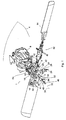
- Fig. 1 shows an exploded view in perspective of a tail rotor 1 provided with a rotor damper 2 according to the invention.
- the tail rotor 1 is arranged on the tail of a helicopter 4, which is only schematically disclosed in fig. 1 .
- the tail rotor 1 comprises a drive shaft 6, which is rotatable arranged in a gearbox 8.
- a hub 12 is arranged at the free end part 10 of the drive shaft 6 .
- Two rotor blades 14 are connected to the hub 12 via a linkage 16, so that the pitch of the blades 14 can be changed during flight of the helicopter 4 in order to manoeuvre the helicopter 4.
- the hub 12 is provided with a first bore 16, which extends through the entire hub 12.
- the dimensions of the first bore 16 is adapted to accommodate the free end part 10 of drive shaft 6 and the hub 12 is connected to the drive shaft 6 in the rotational direction by a pin 18, which extends through a second bore 20 in the hub 12 and trough a substantially diametrically arranged hole 22 in the drive shaft 6.
- the pin 18 is pivotal arranged in the second bore 20 of the hub 12 via bearings 24, such as ball bearings.
- the pin 18 and the bearings 24 are locked in the axial direction of the pin 18 by means of lock plates 26 fixed by screws 28 into the hub 12.
- the rotor damper 2 is made of an elastic material and is arranged in the first bore 16 in the space between the hub 12 and the drive shaft 6. In order to accommodate the rotor damper 2 the dimensions of the first bore 16 is larger than the dimensions of the drive shaft 6.
- the free end part 10 of the drive shaft 6 is substantially circular and the first bore 16 is elongated in a direction which substantially coincides with an axis which extends through the rotor blades 14.
- the outer dimensions of the rotor damper 2 substantially correspond to the inner dimensions of the first bore 16. Therefore, in the embodiment disclosed in fig 1 the rotor damper 2 has a main body 30 which is elongated in a direction perpendicular to is length axis 32. When elongated in a direction perpendicular to is length axis 32 and mounted in the first bore 16 so that the elongated part of the main body 30 substantially coincides with an axis which extends through both rotor blades 14 an effective vibration and dampening effect is achieved when the rotor blades 14 move or vibrate in a direction perpendicular to the rotation plane of the rotor blades 14. The main body 30 then has the possibility to be compressed within the first bore 16 of the hub 12.
- the length axis 32 of the rotor damper 2 substantially coincides with centre axis 34 of the drive shaft 6.
- the main body 30 of the rotor damper 2 is provided with a cylindrical cavity 36 in order to accommodate the free end part 10 of the drive shaft 6.
- the cylindrical cavity 36 has a centre axis which sub-stantially coincides with the length axis 32 of the main body 30 of the rotor damper 2.
- the rotor damper 2 is also provided with a flange 38 connected to the main body 30.
- the flange 38 is made of the same material as the main body 30 of the rotor damper 2.
- the flange 38 is provided with an abutment surface 39 for abutting an outer surface 40 of the hub 12.
- the main body 30 also has an end portion 41 provided with an abutment surface 43 for abutting the distal end 42 of the drive shaft 6 of the tail rotor 1, which abutment surface 43 is substantially parallel to the abutment surface 39 of the flange 38.
- the abutment surfaces 39, 43 of the flange 38 and the end portion 41 have a common plane.
- the distal end 42 of the drive shaft 6 is provided with a threaded hole 44 having a centre axis which substantially coincides with the centre axis 34 of the drive shaft 6.
- a threaded bolt 46 fixates the rotor damper 2 to the drive shaft 6 and in the first bore 16 of the hub 12 when threaded into the threaded hole 44 in the drive shaft 6.
- a support washer 48 is arranged at an outer surface 50 of the end portion 41 of the rotor damper 2 and fixated by the treaded bolt 46.
- the rotor damper 2 is provided with two slits 52 in the main body 30, which slits 52 extends in the direction of the length axis 32 of the main body 30.
- the rotor damper 2 can be mounted in the first bore 16 of the hub 12 by pushing the rotor damper 2 in the axially direction of the drive shaft 6.
- the slits 52 in the main body 30 of the rotor damper 2 thus make it possible for the rotor damper 2 to slide into the intended position in the hub 12 and onto the end part 10 of the drive shaft 6.
- the slits 52 also make it possible to replace the rotor damper 2 with another rotor damper 2 having different damping characteristics.
- the rotor dampers 2 can be made in different materials such as rubber and plastics and also a mix of these materials in order to achieve different dampening characteristics.
- a sleeve 54 may be arranged onto the free end part 10 of the derive shaft 6.
- the rotor damper 2 is arranged over and onto the sleeve 54. Since the main body 30 of the rotor damper 2 is provided with slits 52 the drive shaft 6 and the inner walls of the first bore 16 in the hub 12 may come into contact with each others. The sleeve 54 will therefore prevent the drive shaft 6 and the hub 12 to come into contact and as a result protect the drive shaft 6 and the hub 12 from wear.
- the sleeve 54 is preferably made of a plastic material.
- the sleeve 54 is provided with a substantially diametrical arranged hole 56 to allow the pin 18 to pass through the sleeve 54 when mounted to the free end part 10 of the drive shaft 6.
- Fig. 2 shows a section view along the drive shaft 6 of the tail rotor 1 which is provided with a rotor damper 2 according to the invention.
- the rotor damper 2 is arranged in the space or gap between the drive shaft 6 and the hub 12 and fixed to the distal end 42 of the drive shaft 6 by means of the threaded bolt 46.
- a distance sleeve 58 is arranged on the threaded bolt 46 and the length of the distance sleeve 58 is adapted to the dimensions of the flange 38.
- distance washers 60 are arranged on the outer surface 50 of the end portion 41. Preferably the distance washers 60 are interposed between the support washer 48 and the outer surface 50 of the end portion 41.
- two distance washers 60 are arranged on the outer surface 50 of the end portion 41.
- two distance washers 60 can be adjusted by adding or removing one or more distance washers 60.
- adding a distance washer 60 the pressure from the threaded bolt 46 and the support washer 60 increases on the rotor damper 2 and the material of the rotor damper 2 will therefore be compressed.
- the material of the rotor damper 2 is compressed the resiliency of the rotor damper 2 decreases and the dampening of the tail rotor 1 therefore also decreases.
- Fig. 3 shows a section view along the drive shaft 6 of the tail rotor 1 provided with the rotor damper 2 according to the invention, in an angle of 90° comparing to fig. 2 .
- the pin 18 extends through the drive shaft 6 and the sleeve 54 and is pivotal arranged in the second bore 20 in the hub 12 via the bearings 24. As mentioned above, the pin 18 and the bearings 24 are locked in the axial direction of the pin 18 by means of lock plates 26 fixed by screws 28 into the hub 12. It is also evident from fig. 3 that the sleeve 54 will prevent the drive shaft 6 and the hub 12 to come into contact and as a result protect the shaft 6 and the hub 12 from wear. In the embodiment disclosed in fig. 3 no distance washers 60 are interposed between the outer surface 50 of the end portion 41 of the main body 30 and the support washer 48.
- the helicopter 4 is an unattended vehicle (UAV).
- UAV unattended vehicle
- Such unattended helicopters have smaller dimensions in relation to full size helicopters and therefore also the stresses on the components in the helicopter, such as the drive shafts, couplings, dampers and rotors, are smaller in a UAV in relation to a full size helicopter.
Landscapes
- Engineering & Computer Science (AREA)
- Mechanical Engineering (AREA)
- Aviation & Aerospace Engineering (AREA)
- Vibration Dampers (AREA)
- Turbine Rotor Nozzle Sealing (AREA)
Description
- The present invention relates to a rotor damper for tail rotors of helicopters, according to the preamble of claim 1 and a tail rotor provided with such a rotor damper according to the preamble of claim 9.
- A common type of helicopter is provided with a main rotor and a tail rotor. The main rotor supplies the primary forces for flight of the helicopter and the tail rotor provides stability and influence on the flight direction of the helicopter. The tail rotor of the helicopter is sensitive for wind disturbances which affects the manoeuvrability of the helicopter. These wind disturbances also creates undesirable vibrations which may be transmitted to the fuselage of the helicopter. Also, oscillations of the tail rotor blades are a primary source of undesirable vibrations. Such oscillations may occur from the so-called "scissors mode" motions of the rotor blades in relation to each others. In this mode the blades oscillates relative to the drive shaft and to each others in the plane of rotation of the rotor blades. The oscillations and vibrations generated by the tail rotor are undesirable because they increase the mechanical stress of the components in the helicopter.
- Document
US-A-3999887 discloses a connecting assembly for the tail rotor of a helicopter. The assembly is provided with flexible straps which interconnect the rotor blades with the connecting assembly. The connecting assembly is also provided with layers of a viscoelastic material which are disposed normal to the axis of rotation of the drive shaft. By proper selection of the vis-coelastic material for the layers oscillations and vibrations can be reduced through the damping characteristics of the viscoelastic material. The layers of viscoelastic material are bound to support or cover plates in the connecting assembly. Bolts and nuts lock the cover plates in a fixed position relative to the drive shaft. - Document
US 2164485 A , which is considered to be the closest prior art, discloses a slip clutch device for a propeller, comprising a resilient member arranged between a drive shaft and a hub. The resilient member is constructed such that it permits a slip there between. - The objective problem to be solved by the present invention is to increase the manoeuvrability of a helicopter.
- Another objective problem to be solved by the present invention is to achieve a rotor damper which effectively dampens oscillations and vibrations of a tail rotor of a helicopter.
- A further objective problem to be solved by the present invention is to achieve a rotor damper which is easy to replace and which can be replaced in a short period of time.
- A still further objective problem to be solved by the present invention is to easy and in a short period of time change the damping characteristics of a rotor damper.
- A still further objective problem to be solved by the present invention is to achieve a rotor damper for a tail rotor, which is adapted to an unattended helicopter.
- The above-mentioned objects are achieved by a rotor damper according to claim 1 and a tail rotor according to claim 9.
- Such a rotor damper effectively dampens oscillations and vibrations of a tail rotor of a helicopter. The resilient material in the main body and the flange of the rotor damper will dampen the oscillations and vibrations which emanate from the rotor blades and prevent the oscillations and vibrations from propagate to the drive shaft and further to the helicopter.
- The resilient connection between the hub and the drive shaft also increase the manoeuvrability of the helicopter. When changing the pitch of the rotor blades in order to change the direction of the helicopter the rotor damper prevents jerks and high acceleration forces which may occur in connection with a quick changing in the pitch.
- According to an embodiment of the invention two slits are arranged in the main body, which slits extends in the direction of the length axis. The slits in the main body of the rotor damper thus make it possible for the rotor damper to slide into the intended position in the hub and onto the end part of the drive shaft. The slits also make it possible to replace the rotor damper with another rotor damper having different damping characteristics. According to the embodiment the rotor damper is fixated to the drive shaft and in the first bore of the hub by a treaded bolt which is threaded into a threaded hole in an end surface of the free end part of the drive shaft. This makes it easy and in a short period of time change the damping characteristics of a rotor damper.
- According to an embodiment of the invention a support washer is arranged at an outer surface of the flange of the rotor damper and fixated by the treaded bolt. At least one distance washer is arranged between the support washer and the outer surface of the flange. The effect is that the required dampening characteristics of the tail rotor can be adjusted by adding or removing one or more distance washers.
- According to an embodiment of the invention the helicopter is an unattended vehicle (UAV). Such unattended helicopters have smaller dimensions in relation to full size helicopters and therefore also the stresses on the components in the helicopter, such as the drive shafts, couplings, dampers and rotors, are smaller in an UAV in relation to a full size helicopter.
- Further advantages and features of the invention can be derived from the following detailed description of exemplary embodiments of the invention, with reference to the drawings.
-
Fig. 1 shows an exploded view in perspective of a tail rotor provided with a rotor damper according to the invention, -
Fig. 2 shows a section view along the drive shaft of a tail rotor provided with a rotor damper according to the invention, and -
Fig. 3 shows a section view along the drive shaft of a tail rotor provided with a rotor damper according to the invention, in an angle of 90° comparing tofig. 2 . -
Fig. 1 shows an exploded view in perspective of a tail rotor 1 provided with a rotor damper 2 according to the invention. The tail rotor 1 is arranged on the tail of ahelicopter 4, which is only schematically disclosed infig. 1 . The tail rotor 1 comprises adrive shaft 6, which is rotatable arranged in agearbox 8. At thefree end part 10 of the drive shaft 6 ahub 12 is arranged. Tworotor blades 14 are connected to thehub 12 via alinkage 16, so that the pitch of theblades 14 can be changed during flight of thehelicopter 4 in order to manoeuvre thehelicopter 4. - The
hub 12 is provided with afirst bore 16, which extends through theentire hub 12. The dimensions of thefirst bore 16 is adapted to accommodate thefree end part 10 ofdrive shaft 6 and thehub 12 is connected to thedrive shaft 6 in the rotational direction by apin 18, which extends through asecond bore 20 in thehub 12 and trough a substantially diametrically arrangedhole 22 in thedrive shaft 6. Thepin 18 is pivotal arranged in thesecond bore 20 of thehub 12 viabearings 24, such as ball bearings. Thepin 18 and thebearings 24 are locked in the axial direction of thepin 18 by means oflock plates 26 fixed byscrews 28 into thehub 12. When thedrive shaft 6 is driven by a motor (not disclosed) of thehelicopter 4 the torque from thedrive shaft 6 will be transferred to thehub 12 via thepin 18. - The rotor damper 2 is made of an elastic material and is arranged in the
first bore 16 in the space between thehub 12 and thedrive shaft 6. In order to accommodate the rotor damper 2 the dimensions of thefirst bore 16 is larger than the dimensions of thedrive shaft 6. In the embodiment disclosed infig. 1 thefree end part 10 of thedrive shaft 6 is substantially circular and thefirst bore 16 is elongated in a direction which substantially coincides with an axis which extends through therotor blades 14. - The outer dimensions of the rotor damper 2 substantially correspond to the inner dimensions of the
first bore 16. Therefore, in the embodiment disclosed infig 1 the rotor damper 2 has amain body 30 which is elongated in a direction perpendicular to islength axis 32. When elongated in a direction perpendicular to islength axis 32 and mounted in thefirst bore 16 so that the elongated part of themain body 30 substantially coincides with an axis which extends through bothrotor blades 14 an effective vibration and dampening effect is achieved when therotor blades 14 move or vibrate in a direction perpendicular to the rotation plane of therotor blades 14. Themain body 30 then has the possibility to be compressed within thefirst bore 16 of thehub 12. Thelength axis 32 of the rotor damper 2 substantially coincides withcentre axis 34 of thedrive shaft 6. Themain body 30 of the rotor damper 2 is provided with acylindrical cavity 36 in order to accommodate thefree end part 10 of thedrive shaft 6. Thecylindrical cavity 36 has a centre axis which sub-stantially coincides with thelength axis 32 of themain body 30 of the rotor damper 2. The rotor damper 2 is also provided with aflange 38 connected to themain body 30. Preferably theflange 38 is made of the same material as themain body 30 of the rotor damper 2. Theflange 38 is provided with anabutment surface 39 for abutting anouter surface 40 of thehub 12. When mounted in thefirst bore 16 of thehub 12 and connected to thedrive shaft 6 theabutment surface 39 of theflange 38 of the rotor damper 2 will abut theouter surface 40 of thehub 12. Themain body 30 also has anend portion 41 provided with anabutment surface 43 for abutting thedistal end 42 of thedrive shaft 6 of the tail rotor 1, which abutmentsurface 43 is substantially parallel to theabutment surface 39 of theflange 38. The abutment surfaces 39, 43 of theflange 38 and theend portion 41 have a common plane. Thedistal end 42 of thedrive shaft 6 is provided with a threadedhole 44 having a centre axis which substantially coincides with thecentre axis 34 of thedrive shaft 6. A threadedbolt 46 fixates the rotor damper 2 to thedrive shaft 6 and in thefirst bore 16 of thehub 12 when threaded into the threadedhole 44 in thedrive shaft 6. Preferably asupport washer 48 is arranged at anouter surface 50 of theend portion 41 of the rotor damper 2 and fixated by thetreaded bolt 46. - The rotor damper 2 is provided with two
slits 52 in themain body 30, which slits 52 extends in the direction of thelength axis 32 of themain body 30. When thehub 12 is mounted on thedrive shaft 6 and thepin 18 extends trough thesecond bore 20 in thehub 12 and trough a substantially diametrically arrangedhole 22 in thedrive shaft 6 the rotor damper 2 can be mounted in thefirst bore 16 of thehub 12 by pushing the rotor damper 2 in the axially direction of thedrive shaft 6. Theslits 52 in themain body 30 of the rotor damper 2 thus make it possible for the rotor damper 2 to slide into the intended position in thehub 12 and onto theend part 10 of thedrive shaft 6. Theslits 52 also make it possible to replace the rotor damper 2 with another rotor damper 2 having different damping characteristics. The rotor dampers 2 can be made in different materials such as rubber and plastics and also a mix of these materials in order to achieve different dampening characteristics. - In the embodiment disclosed in
fig. 1 asleeve 54 may be arranged onto thefree end part 10 of the deriveshaft 6. The rotor damper 2 is arranged over and onto thesleeve 54. Since themain body 30 of the rotor damper 2 is provided withslits 52 thedrive shaft 6 and the inner walls of thefirst bore 16 in thehub 12 may come into contact with each others. Thesleeve 54 will therefore prevent thedrive shaft 6 and thehub 12 to come into contact and as a result protect thedrive shaft 6 and thehub 12 from wear. Thesleeve 54 is preferably made of a plastic material. Thesleeve 54 is provided with a substantially diametrical arranged hole 56 to allow thepin 18 to pass through thesleeve 54 when mounted to thefree end part 10 of thedrive shaft 6. -
Fig. 2 shows a section view along thedrive shaft 6 of the tail rotor 1 which is provided with a rotor damper 2 according to the invention. The rotor damper 2 is arranged in the space or gap between thedrive shaft 6 and thehub 12 and fixed to thedistal end 42 of thedrive shaft 6 by means of the threadedbolt 46. Adistance sleeve 58 is arranged on the threadedbolt 46 and the length of thedistance sleeve 58 is adapted to the dimensions of theflange 38. Also,distance washers 60 are arranged on theouter surface 50 of theend portion 41. Preferably thedistance washers 60 are interposed between thesupport washer 48 and theouter surface 50 of theend portion 41. In the disclosed embodiment offig. 2 , twodistance washers 60 are arranged on theouter surface 50 of theend portion 41. As an alternative or a complement to replace the rotor damper 2 in order to achieve the required dampening characteristics of the tail rotor 1 can be adjusted by adding or removing one ormore distance washers 60. When adding adistance washer 60 the pressure from the threadedbolt 46 and thesupport washer 60 increases on the rotor damper 2 and the material of the rotor damper 2 will therefore be compressed. When the material of the rotor damper 2 is compressed the resiliency of the rotor damper 2 decreases and the dampening of the tail rotor 1 therefore also decreases. If adistance washer 60 is removed the pressure from the threadedbolt 46 and thesupport washer 48 decreases on the rotor damper 2 and the material of the rotor damper 2 will therefore be allowed to expand. When the material of the rotor damper 2 is allowed to expand the resiliency of the rotor damper 2 increases and the dampening of the tail rotor 1 therefore also increases. Infig. 2 also thesleeve 54 arranged on thedrive shaft 6 is disclosed. Also, theconnection arrangement 62 of therotor blades 14 to thehub 12 is disclosed. The pitch of therotor blades 14 can be changed by adrive mechanism 64. -
Fig. 3 shows a section view along thedrive shaft 6 of the tail rotor 1 provided with the rotor damper 2 according to the invention, in an angle of 90° comparing tofig. 2 . Thepin 18 extends through thedrive shaft 6 and thesleeve 54 and is pivotal arranged in thesecond bore 20 in thehub 12 via thebearings 24. As mentioned above, thepin 18 and thebearings 24 are locked in the axial direction of thepin 18 by means oflock plates 26 fixed byscrews 28 into thehub 12. It is also evident fromfig. 3 that thesleeve 54 will prevent thedrive shaft 6 and thehub 12 to come into contact and as a result protect theshaft 6 and thehub 12 from wear. In the embodiment disclosed infig. 3 nodistance washers 60 are interposed between theouter surface 50 of theend portion 41 of themain body 30 and thesupport washer 48. - According to an embodiment of the invention the
helicopter 4 is an unattended vehicle (UAV). Such unattended helicopters have smaller dimensions in relation to full size helicopters and therefore also the stresses on the components in the helicopter, such as the drive shafts, couplings, dampers and rotors, are smaller in a UAV in relation to a full size helicopter.
Claims (14)
- A rotor damper for a tail rotor (1) of a helicopter (4), comprising a main body (30) of a resilient material to be arranged between a drive shaft (6) for the tail rotor (1) and a hub (12) on which rotor blades (14) for the tail rotor (1) is coupled, wherein a flange (38) is connected to the main body (30) of the rotor damper (2), which flange (38) is provided with an abutment surface (39) for abutting an outer surface (50) of the hub (12), characterised in that the main body (30) has an end portion (41) provided with an abutment surface (43) for abutting a distal end (42) of the drive shaft (6) of the tail rotor (1), which abutment surface (43) is substantially parallel to the abutment surface (39) of the flange (38).
- A rotor damper according to claim 1, characterised in that the main body (30) of the rotor damper (2) is elongated in a direction perpendicular to is length axis (32).
- A rotor damper according to any of claims 1 - 2, characterised in that flange (38) is made of the same material as the main body (30) of the rotor damper (2).
- A rotor damper according to any of the preceding claims, characterised in that the abutment surfaces (39, 43) of the flange (38) and the end portion (41) has a common plane.
- A rotor damper according to any of the preceding claims, characterised in that a central hole (56) is arranged in the end portion (41), which central hole (56) has a centre axis which coincides with the length axis (32) of the main body (30).
- A rotor damper according to any of the preceding claims, characterised in that two slits (52) are arranged in the main body (30), which slits (52) extend in the direction of the length axis (32) of the main body (30).
- A rotor damper according to any of the preceding claims, characterised in that the material in the rotor damper (2) is rubber, plastic or a combination of rubber and plastic.
- A tail rotor for a helicopter (4), comprising a drive shaft (6) with a free end part (10) and a hub (12) on which rotor blades (14) for the tail rotor (1) is coupled; the hub (12) is provided with a first bore (16), which extends through the entire hub (12), and which first bore (16) is adapted to accommodate the free end part (10) of drive shaft (6), characterised in that a rotor damper (2) according any of claims 1 - 7 is arranged between a drive shaft (6) for the tail rotor (1) and a hub (12).
- A tail rotor according to claim 8, characterised in that the rotor damper (2) is fixated to the drive shaft (6) and in the first bore (16) of the hub (12) by a treaded bolt (46) which is threaded into a threaded hole (44) in a distal end (42) of the free end part (10) of the drive shaft (6).
- A tail rotor according to claim 9, characterised in that a support washer (48) is arranged at an outer surface (50) of an end portion (41) of the rotor damper (2) and fixated by the treaded bolt (46).
- A tail rotor according to claim 10, characterised in that at least one distance washer (60) is arranged between the support washer (48) and the outer surface (50) of the end portion (41).
- A tail rotor according to any of claims 8 - 11, characterised in that hub (12) is connected to the drive shaft (6) by a pin (18), which extends through a second bore (20) in the hub (12) and through a substantially diametrically arranged hole (22) in the drive shaft (6).
- A tail rotor according to claim 12, characterised in that the pin (18) pass through the slits (52) in the main body (30) of the rotor damper (2).
- A tail rotor according to any of claims 8 - 13, characterised in that the helicopter (4) is an unattended vehicle.
Applications Claiming Priority (1)
| Application Number | Priority Date | Filing Date | Title |
|---|---|---|---|
| PCT/SE2009/050645 WO2010140933A1 (en) | 2009-06-02 | 2009-06-02 | Rotor damper and tail rotor with such a rotor damper |
Publications (3)
| Publication Number | Publication Date |
|---|---|
| EP2437979A1 EP2437979A1 (en) | 2012-04-11 |
| EP2437979A4 EP2437979A4 (en) | 2015-04-22 |
| EP2437979B1 true EP2437979B1 (en) | 2016-10-26 |
Family
ID=43297921
Family Applications (1)
| Application Number | Title | Priority Date | Filing Date |
|---|---|---|---|
| EP09845603.1A Active EP2437979B1 (en) | 2009-06-02 | 2009-06-02 | Rotor damper and tail rotor with such a rotor damper |
Country Status (5)
| Country | Link |
|---|---|
| US (1) | US9073636B2 (en) |
| EP (1) | EP2437979B1 (en) |
| BR (1) | BRPI0924584A2 (en) |
| ES (1) | ES2612127T3 (en) |
| WO (1) | WO2010140933A1 (en) |
Cited By (1)
| Publication number | Priority date | Publication date | Assignee | Title |
|---|---|---|---|---|
| CN106516107A (en) * | 2016-11-08 | 2017-03-22 | 芜湖万户航空航天科技有限公司 | Tail slurry clamp shaft |
Families Citing this family (3)
| Publication number | Priority date | Publication date | Assignee | Title |
|---|---|---|---|---|
| JP5801851B2 (en) | 2013-06-28 | 2015-10-28 | ヤマハ発動機株式会社 | Unmanned helicopter |
| JP6102602B2 (en) | 2013-07-23 | 2017-03-29 | ソニー株式会社 | Image processing apparatus, image processing method, image processing program, and imaging apparatus |
| CN106438663A (en) * | 2016-11-08 | 2017-02-22 | 芜湖万户航空航天科技有限公司 | Unmanned plane propeller shaft clamping assembly |
Citations (1)
| Publication number | Priority date | Publication date | Assignee | Title |
|---|---|---|---|---|
| US2164485A (en) * | 1938-10-21 | 1939-07-04 | Gen Motors Corp | Slip clutch device |
Family Cites Families (34)
| Publication number | Priority date | Publication date | Assignee | Title |
|---|---|---|---|---|
| GB478676A (en) * | 1936-07-24 | 1938-01-24 | Leon Thiry | Improvements in or relating to apparatus for transmitting power from a propeller shaft to a propeller |
| US2235605A (en) * | 1937-03-10 | 1941-03-18 | Bugatti Ettore | Screw propeller |
| US2312822A (en) * | 1937-07-15 | 1943-03-02 | Julien Maurice Franc Alexandre | Resilient suspension, particularly for bodies driven with a rotary motion |
| US2556151A (en) * | 1946-05-01 | 1951-06-05 | Morse Chain Co | Quick detachable hub |
| US3045763A (en) * | 1959-10-26 | 1962-07-24 | Perrott William | Shock absorbing positive drive means for marine propellers |
| US3084963A (en) * | 1960-07-29 | 1963-04-09 | Lau Blower Co | Resilent fan hub assembly |
| US3256939A (en) * | 1965-01-11 | 1966-06-21 | Matthew J Novak | Marine propeller |
| US3477794A (en) * | 1967-02-14 | 1969-11-11 | Columbian Bronze Corp | Yielding bushing |
| US3575530A (en) * | 1968-09-05 | 1971-04-20 | Clifton W Hall | Variable pitch propeller |
| US3594892A (en) * | 1969-04-14 | 1971-07-27 | Clevite Corp | Method of producing a multiple compression rate bushing |
| US3701611A (en) * | 1970-12-21 | 1972-10-31 | Outboard Marine Corp | Marine propeller with resilient hub structure |
| FR2285298A1 (en) * | 1974-09-19 | 1976-04-16 | Aerospatiale | TAIL ROTOR ARRANGEMENT FOR GIRAVIONS |
| FR2310920A1 (en) * | 1975-05-14 | 1976-12-10 | Aerospatiale | ROTOR ARRANGEMENT FOR ROTATING BLADE AIRCRAFT |
| US4008980A (en) * | 1975-06-26 | 1977-02-22 | United Technologies Corporation | Composite helicopter spar and means to alleviate stress concentration |
| US3999887A (en) | 1975-07-09 | 1976-12-28 | Lord Corporation | Propeller assembly |
| CA1113912A (en) * | 1977-08-11 | 1981-12-08 | Larry W. Dooley | Compound hub spring system for helicopters |
| US4381902A (en) * | 1979-12-20 | 1983-05-03 | Hughes Helicopters, Inc. | Helicopter tail rotor of the elastomerically-mounted composite flexbeam type |
| US4452591A (en) * | 1980-08-26 | 1984-06-05 | The Goodyear Tire & Rubber Company | Resilient rotary coupling |
| US4382566A (en) * | 1980-12-05 | 1983-05-10 | Rolf Brand | Lightweight aircraft |
| US4566855A (en) * | 1981-08-28 | 1986-01-28 | Costabile John J | Shock absorbing clutch assembly for marine propeller |
| US4522563A (en) * | 1982-07-06 | 1985-06-11 | Bell Helicopter Textron, Inc. | Elastomeric system for mounting a helicopter rotor |
| US4642057A (en) * | 1983-12-19 | 1987-02-10 | Brunswick Corporation | Shock absorbing propeller |
| US4595337A (en) * | 1984-12-20 | 1986-06-17 | Crowe Scott D | Hub for wind machines |
| DE3804203C1 (en) * | 1988-02-11 | 1989-08-17 | Messerschmitt-Boelkow-Blohm Gmbh, 8012 Ottobrunn, De | |
| US5340279A (en) * | 1992-06-22 | 1994-08-23 | United Technologies Corporation | Snubber assembly for a rotor assembly having ducted, coaxial counter-rotating rotors |
| US5667311A (en) * | 1995-03-27 | 1997-09-16 | Maers; Walter | Pivot shaft for a damper assembly |
| US6085384A (en) * | 1999-04-08 | 2000-07-11 | Illinois Tool Works Inc. | One-way hinge damper |
| US6471481B2 (en) * | 2001-01-02 | 2002-10-29 | Turning Point Propellers, Inc. | Hub assembly for marine propeller |
| US6764280B2 (en) * | 2001-03-06 | 2004-07-20 | Bell Helicopter Textron Inc. | Multi-bladed tail rotor hub design for coriolis relief |
| SE521357C2 (en) | 2001-03-30 | 2003-10-28 | Nordic Windpower Ab | Hub for a wind turbine in a wind turbine and a wind turbine with such a hub |
| US7223073B2 (en) * | 2005-05-19 | 2007-05-29 | Peter Dean | Boat propeller |
| US20070177978A1 (en) * | 2006-01-31 | 2007-08-02 | Zhongshan Broad-Ocean Motor Co., Ltd. | Damping structure for a rotor assembly of a motor |
| US20090016896A1 (en) * | 2007-05-25 | 2009-01-15 | Hill Daryl G | Conical washer system for propeller stabilization |
| EP2184229B1 (en) * | 2008-11-11 | 2012-10-17 | AGUSTAWESTLAND S.p.A. | Helicopter rotor |
-
2009
- 2009-06-02 US US13/375,964 patent/US9073636B2/en active Active
- 2009-06-02 ES ES09845603.1T patent/ES2612127T3/en active Active
- 2009-06-02 WO PCT/SE2009/050645 patent/WO2010140933A1/en not_active Ceased
- 2009-06-02 EP EP09845603.1A patent/EP2437979B1/en active Active
- 2009-06-02 BR BRPI0924584A patent/BRPI0924584A2/en not_active IP Right Cessation
Patent Citations (1)
| Publication number | Priority date | Publication date | Assignee | Title |
|---|---|---|---|---|
| US2164485A (en) * | 1938-10-21 | 1939-07-04 | Gen Motors Corp | Slip clutch device |
Cited By (1)
| Publication number | Priority date | Publication date | Assignee | Title |
|---|---|---|---|---|
| CN106516107A (en) * | 2016-11-08 | 2017-03-22 | 芜湖万户航空航天科技有限公司 | Tail slurry clamp shaft |
Also Published As
| Publication number | Publication date |
|---|---|
| EP2437979A4 (en) | 2015-04-22 |
| WO2010140933A1 (en) | 2010-12-09 |
| EP2437979A1 (en) | 2012-04-11 |
| ES2612127T3 (en) | 2017-05-12 |
| US9073636B2 (en) | 2015-07-07 |
| US20120148409A1 (en) | 2012-06-14 |
| BRPI0924584A2 (en) | 2019-09-24 |
Similar Documents
| Publication | Publication Date | Title |
|---|---|---|
| RU2499734C2 (en) | Helicopter rotor and helicopter with said rotor | |
| RU2517643C2 (en) | Helicopter rotor and helicopter with said rotor (versions) | |
| KR101281162B1 (en) | A rotorcraft rotor with blades hinged in flap and in lag | |
| US11767105B2 (en) | Mount for supporting a component and attenuating noise | |
| US11040771B2 (en) | Rotor hub | |
| US9073636B2 (en) | Rotor damper and tail rotor with such a rotor damper | |
| US6764280B2 (en) | Multi-bladed tail rotor hub design for coriolis relief | |
| KR101634184B1 (en) | Helicopter | |
| US20140308123A1 (en) | Bearing for rotor blade | |
| EP3208192B1 (en) | Vibration damping device and damping method for a rotor of an aircraft capable of hovering | |
| US10752346B2 (en) | Rotor assembly with composite static mast | |
| CA2820936C (en) | Elastomeric bearing housing and mating grip for helicopter rotor system | |
| EP2390180B1 (en) | Non-rotating universal joint for a helicopter drive unit | |
| KR101227106B1 (en) | A blade damper, and a rotor fitted with such a damper | |
| US11655020B2 (en) | Non rotationally constrained friction damper for drive shaft | |
| US11142307B2 (en) | Lead-lag damper integrated inside a blade of a rotor | |
| US20220268320A1 (en) | Overload coupling for rotating drive systems | |
| JP6600673B2 (en) | Flexible joint | |
| WO2016025491A1 (en) | Viscous damper | |
| US20030083134A1 (en) | Flexible coupling device | |
| CN121368687A (en) | Vibration isolator |
Legal Events
| Date | Code | Title | Description |
|---|---|---|---|
| PUAI | Public reference made under article 153(3) epc to a published international application that has entered the european phase |
Free format text: ORIGINAL CODE: 0009012 |
|
| 17P | Request for examination filed |
Effective date: 20111212 |
|
| AK | Designated contracting states |
Kind code of ref document: A1 Designated state(s): AT BE BG CH CY CZ DE DK EE ES FI FR GB GR HR HU IE IS IT LI LT LU LV MC MK MT NL NO PL PT RO SE SI SK TR |
|
| DAX | Request for extension of the european patent (deleted) | ||
| RA4 | Supplementary search report drawn up and despatched (corrected) |
Effective date: 20150325 |
|
| RIC1 | Information provided on ipc code assigned before grant |
Ipc: B64C 27/35 20060101ALI20150319BHEP Ipc: B64C 27/82 20060101AFI20150319BHEP Ipc: B64C 11/12 20060101ALI20150319BHEP Ipc: B64C 27/51 20060101ALI20150319BHEP Ipc: B64C 27/00 20060101ALN20150319BHEP |
|
| 17Q | First examination report despatched |
Effective date: 20151126 |
|
| GRAP | Despatch of communication of intention to grant a patent |
Free format text: ORIGINAL CODE: EPIDOSNIGR1 |
|
| RIC1 | Information provided on ipc code assigned before grant |
Ipc: B64C 11/12 20060101ALI20160422BHEP Ipc: B64C 27/35 20060101ALI20160422BHEP Ipc: B64C 27/00 20060101ALN20160422BHEP Ipc: B64C 27/51 20060101ALI20160422BHEP Ipc: B64C 27/82 20060101AFI20160422BHEP |
|
| INTG | Intention to grant announced |
Effective date: 20160510 |
|
| GRAS | Grant fee paid |
Free format text: ORIGINAL CODE: EPIDOSNIGR3 |
|
| RAP1 | Party data changed (applicant data changed or rights of an application transferred) |
Owner name: UMS SKELDAR SWEDEN AB |
|
| GRAA | (expected) grant |
Free format text: ORIGINAL CODE: 0009210 |
|
| AK | Designated contracting states |
Kind code of ref document: B1 Designated state(s): AT BE BG CH CY CZ DE DK EE ES FI FR GB GR HR HU IE IS IT LI LT LU LV MC MK MT NL NO PL PT RO SE SI SK TR |
|
| REG | Reference to a national code |
Ref country code: GB Ref legal event code: FG4D |
|
| REG | Reference to a national code |
Ref country code: CH Ref legal event code: EP |
|
| REG | Reference to a national code |
Ref country code: AT Ref legal event code: REF Ref document number: 839805 Country of ref document: AT Kind code of ref document: T Effective date: 20161115 |
|
| REG | Reference to a national code |
Ref country code: IE Ref legal event code: FG4D |
|
| REG | Reference to a national code |
Ref country code: DE Ref legal event code: R096 Ref document number: 602009042022 Country of ref document: DE |
|
| REG | Reference to a national code |
Ref country code: SE Ref legal event code: TRGR |
|
| REG | Reference to a national code |
Ref country code: LT Ref legal event code: MG4D |
|
| PG25 | Lapsed in a contracting state [announced via postgrant information from national office to epo] |
Ref country code: LV Free format text: LAPSE BECAUSE OF FAILURE TO SUBMIT A TRANSLATION OF THE DESCRIPTION OR TO PAY THE FEE WITHIN THE PRESCRIBED TIME-LIMIT Effective date: 20161026 |
|
| REG | Reference to a national code |
Ref country code: NL Ref legal event code: MP Effective date: 20161026 |
|
| PG25 | Lapsed in a contracting state [announced via postgrant information from national office to epo] |
Ref country code: GR Free format text: LAPSE BECAUSE OF FAILURE TO SUBMIT A TRANSLATION OF THE DESCRIPTION OR TO PAY THE FEE WITHIN THE PRESCRIBED TIME-LIMIT Effective date: 20170127 Ref country code: LT Free format text: LAPSE BECAUSE OF FAILURE TO SUBMIT A TRANSLATION OF THE DESCRIPTION OR TO PAY THE FEE WITHIN THE PRESCRIBED TIME-LIMIT Effective date: 20161026 Ref country code: NO Free format text: LAPSE BECAUSE OF FAILURE TO SUBMIT A TRANSLATION OF THE DESCRIPTION OR TO PAY THE FEE WITHIN THE PRESCRIBED TIME-LIMIT Effective date: 20170126 |
|
| REG | Reference to a national code |
Ref country code: ES Ref legal event code: FG2A Ref document number: 2612127 Country of ref document: ES Kind code of ref document: T3 Effective date: 20170512 |
|
| PG25 | Lapsed in a contracting state [announced via postgrant information from national office to epo] |
Ref country code: FI Free format text: LAPSE BECAUSE OF FAILURE TO SUBMIT A TRANSLATION OF THE DESCRIPTION OR TO PAY THE FEE WITHIN THE PRESCRIBED TIME-LIMIT Effective date: 20161026 Ref country code: PL Free format text: LAPSE BECAUSE OF FAILURE TO SUBMIT A TRANSLATION OF THE DESCRIPTION OR TO PAY THE FEE WITHIN THE PRESCRIBED TIME-LIMIT Effective date: 20161026 Ref country code: NL Free format text: LAPSE BECAUSE OF FAILURE TO SUBMIT A TRANSLATION OF THE DESCRIPTION OR TO PAY THE FEE WITHIN THE PRESCRIBED TIME-LIMIT Effective date: 20161026 Ref country code: PT Free format text: LAPSE BECAUSE OF FAILURE TO SUBMIT A TRANSLATION OF THE DESCRIPTION OR TO PAY THE FEE WITHIN THE PRESCRIBED TIME-LIMIT Effective date: 20170227 Ref country code: IS Free format text: LAPSE BECAUSE OF FAILURE TO SUBMIT A TRANSLATION OF THE DESCRIPTION OR TO PAY THE FEE WITHIN THE PRESCRIBED TIME-LIMIT Effective date: 20170226 Ref country code: BE Free format text: LAPSE BECAUSE OF FAILURE TO SUBMIT A TRANSLATION OF THE DESCRIPTION OR TO PAY THE FEE WITHIN THE PRESCRIBED TIME-LIMIT Effective date: 20161026 Ref country code: HR Free format text: LAPSE BECAUSE OF FAILURE TO SUBMIT A TRANSLATION OF THE DESCRIPTION OR TO PAY THE FEE WITHIN THE PRESCRIBED TIME-LIMIT Effective date: 20161026 |
|
| REG | Reference to a national code |
Ref country code: FR Ref legal event code: PLFP Year of fee payment: 9 |
|
| REG | Reference to a national code |
Ref country code: DE Ref legal event code: R097 Ref document number: 602009042022 Country of ref document: DE |
|
| PG25 | Lapsed in a contracting state [announced via postgrant information from national office to epo] |
Ref country code: CZ Free format text: LAPSE BECAUSE OF FAILURE TO SUBMIT A TRANSLATION OF THE DESCRIPTION OR TO PAY THE FEE WITHIN THE PRESCRIBED TIME-LIMIT Effective date: 20161026 Ref country code: EE Free format text: LAPSE BECAUSE OF FAILURE TO SUBMIT A TRANSLATION OF THE DESCRIPTION OR TO PAY THE FEE WITHIN THE PRESCRIBED TIME-LIMIT Effective date: 20161026 Ref country code: RO Free format text: LAPSE BECAUSE OF FAILURE TO SUBMIT A TRANSLATION OF THE DESCRIPTION OR TO PAY THE FEE WITHIN THE PRESCRIBED TIME-LIMIT Effective date: 20161026 Ref country code: DK Free format text: LAPSE BECAUSE OF FAILURE TO SUBMIT A TRANSLATION OF THE DESCRIPTION OR TO PAY THE FEE WITHIN THE PRESCRIBED TIME-LIMIT Effective date: 20161026 Ref country code: SK Free format text: LAPSE BECAUSE OF FAILURE TO SUBMIT A TRANSLATION OF THE DESCRIPTION OR TO PAY THE FEE WITHIN THE PRESCRIBED TIME-LIMIT Effective date: 20161026 |
|
| PG25 | Lapsed in a contracting state [announced via postgrant information from national office to epo] |
Ref country code: BG Free format text: LAPSE BECAUSE OF FAILURE TO SUBMIT A TRANSLATION OF THE DESCRIPTION OR TO PAY THE FEE WITHIN THE PRESCRIBED TIME-LIMIT Effective date: 20170126 Ref country code: IT Free format text: LAPSE BECAUSE OF FAILURE TO SUBMIT A TRANSLATION OF THE DESCRIPTION OR TO PAY THE FEE WITHIN THE PRESCRIBED TIME-LIMIT Effective date: 20161026 |
|
| PLBE | No opposition filed within time limit |
Free format text: ORIGINAL CODE: 0009261 |
|
| STAA | Information on the status of an ep patent application or granted ep patent |
Free format text: STATUS: NO OPPOSITION FILED WITHIN TIME LIMIT |
|
| 26N | No opposition filed |
Effective date: 20170727 |
|
| PG25 | Lapsed in a contracting state [announced via postgrant information from national office to epo] |
Ref country code: SI Free format text: LAPSE BECAUSE OF FAILURE TO SUBMIT A TRANSLATION OF THE DESCRIPTION OR TO PAY THE FEE WITHIN THE PRESCRIBED TIME-LIMIT Effective date: 20161026 |
|
| PG25 | Lapsed in a contracting state [announced via postgrant information from national office to epo] |
Ref country code: MC Free format text: LAPSE BECAUSE OF FAILURE TO SUBMIT A TRANSLATION OF THE DESCRIPTION OR TO PAY THE FEE WITHIN THE PRESCRIBED TIME-LIMIT Effective date: 20161026 |
|
| REG | Reference to a national code |
Ref country code: CH Ref legal event code: PL |
|
| GBPC | Gb: european patent ceased through non-payment of renewal fee |
Effective date: 20170602 |
|
| REG | Reference to a national code |
Ref country code: IE Ref legal event code: MM4A |
|
| PG25 | Lapsed in a contracting state [announced via postgrant information from national office to epo] |
Ref country code: CH Free format text: LAPSE BECAUSE OF NON-PAYMENT OF DUE FEES Effective date: 20170630 Ref country code: LI Free format text: LAPSE BECAUSE OF NON-PAYMENT OF DUE FEES Effective date: 20170630 Ref country code: GB Free format text: LAPSE BECAUSE OF NON-PAYMENT OF DUE FEES Effective date: 20170602 Ref country code: LU Free format text: LAPSE BECAUSE OF NON-PAYMENT OF DUE FEES Effective date: 20170602 Ref country code: IE Free format text: LAPSE BECAUSE OF NON-PAYMENT OF DUE FEES Effective date: 20170602 |
|
| REG | Reference to a national code |
Ref country code: FR Ref legal event code: PLFP Year of fee payment: 10 |
|
| PG25 | Lapsed in a contracting state [announced via postgrant information from national office to epo] |
Ref country code: MT Free format text: LAPSE BECAUSE OF NON-PAYMENT OF DUE FEES Effective date: 20170602 |
|
| REG | Reference to a national code |
Ref country code: AT Ref legal event code: UEP Ref document number: 839805 Country of ref document: AT Kind code of ref document: T Effective date: 20161026 |
|
| PG25 | Lapsed in a contracting state [announced via postgrant information from national office to epo] |
Ref country code: HU Free format text: LAPSE BECAUSE OF FAILURE TO SUBMIT A TRANSLATION OF THE DESCRIPTION OR TO PAY THE FEE WITHIN THE PRESCRIBED TIME-LIMIT; INVALID AB INITIO Effective date: 20090602 |
|
| PG25 | Lapsed in a contracting state [announced via postgrant information from national office to epo] |
Ref country code: CY Free format text: LAPSE BECAUSE OF NON-PAYMENT OF DUE FEES Effective date: 20161026 |
|
| PG25 | Lapsed in a contracting state [announced via postgrant information from national office to epo] |
Ref country code: MK Free format text: LAPSE BECAUSE OF FAILURE TO SUBMIT A TRANSLATION OF THE DESCRIPTION OR TO PAY THE FEE WITHIN THE PRESCRIBED TIME-LIMIT Effective date: 20161026 |
|
| PG25 | Lapsed in a contracting state [announced via postgrant information from national office to epo] |
Ref country code: TR Free format text: LAPSE BECAUSE OF FAILURE TO SUBMIT A TRANSLATION OF THE DESCRIPTION OR TO PAY THE FEE WITHIN THE PRESCRIBED TIME-LIMIT Effective date: 20161026 |
|
| P01 | Opt-out of the competence of the unified patent court (upc) registered |
Effective date: 20230525 |
|
| PGFP | Annual fee paid to national office [announced via postgrant information from national office to epo] |
Ref country code: DE Payment date: 20250521 Year of fee payment: 17 |
|
| PGFP | Annual fee paid to national office [announced via postgrant information from national office to epo] |
Ref country code: FR Payment date: 20250423 Year of fee payment: 17 |
|
| PGFP | Annual fee paid to national office [announced via postgrant information from national office to epo] |
Ref country code: AT Payment date: 20250519 Year of fee payment: 17 |
|
| PGFP | Annual fee paid to national office [announced via postgrant information from national office to epo] |
Ref country code: SE Payment date: 20250414 Year of fee payment: 17 |
|
| PGFP | Annual fee paid to national office [announced via postgrant information from national office to epo] |
Ref country code: ES Payment date: 20250829 Year of fee payment: 17 |