EP2437373A2 - Power supply apparatus, power supply system and method of supplying power thereof - Google Patents
Power supply apparatus, power supply system and method of supplying power thereof Download PDFInfo
- Publication number
- EP2437373A2 EP2437373A2 EP11172602A EP11172602A EP2437373A2 EP 2437373 A2 EP2437373 A2 EP 2437373A2 EP 11172602 A EP11172602 A EP 11172602A EP 11172602 A EP11172602 A EP 11172602A EP 2437373 A2 EP2437373 A2 EP 2437373A2
- Authority
- EP
- European Patent Office
- Prior art keywords
- output
- power converter
- power
- solar cell
- driving
- Prior art date
- Legal status (The legal status is an assumption and is not a legal conclusion. Google has not performed a legal analysis and makes no representation as to the accuracy of the status listed.)
- Granted
Links
Images


Classifications
-
- H—ELECTRICITY
- H02—GENERATION; CONVERSION OR DISTRIBUTION OF ELECTRIC POWER
- H02J—ELECTRIC POWER NETWORKS; CIRCUIT ARRANGEMENTS OR SYSTEMS FOR SUPPLYING OR DISTRIBUTING ELECTRIC POWER; SYSTEMS FOR STORING ELECTRIC ENERGY
- H02J7/00—Circuit arrangements for charging or discharging batteries or for supplying loads from batteries
- H02J7/34—Parallel operation in networks using both storage and other DC sources, e.g. providing buffering
- H02J7/35—Parallel operation in networks using both storage and other DC sources, e.g. providing buffering with light sensitive cells
-
- H—ELECTRICITY
- H02—GENERATION; CONVERSION OR DISTRIBUTION OF ELECTRIC POWER
- H02H—EMERGENCY PROTECTIVE CIRCUIT ARRANGEMENTS
- H02H7/00—Emergency protective circuit arrangements specially adapted for specific types of electric machines or apparatus or for sectionalised protection of cable or line systems, and effecting automatic switching in the event of an undesired change from normal working conditions
- H02H7/10—Emergency protective circuit arrangements specially adapted for specific types of electric machines or apparatus or for sectionalised protection of cable or line systems, and effecting automatic switching in the event of an undesired change from normal working conditions for converters; for rectifiers
- H02H7/12—Emergency protective circuit arrangements specially adapted for specific types of electric machines or apparatus or for sectionalised protection of cable or line systems, and effecting automatic switching in the event of an undesired change from normal working conditions for converters; for rectifiers for static converters or rectifiers
- H02H7/1213—Emergency protective circuit arrangements specially adapted for specific types of electric machines or apparatus or for sectionalised protection of cable or line systems, and effecting automatic switching in the event of an undesired change from normal working conditions for converters; for rectifiers for static converters or rectifiers for DC-DC converters
-
- H—ELECTRICITY
- H02—GENERATION; CONVERSION OR DISTRIBUTION OF ELECTRIC POWER
- H02J—ELECTRIC POWER NETWORKS; CIRCUIT ARRANGEMENTS OR SYSTEMS FOR SUPPLYING OR DISTRIBUTING ELECTRIC POWER; SYSTEMS FOR STORING ELECTRIC ENERGY
- H02J7/00—Circuit arrangements for charging or discharging batteries or for supplying loads from batteries
- H02J7/34—Parallel operation in networks using both storage and other DC sources, e.g. providing buffering
- H02J7/345—Parallel operation in networks using both storage and other DC sources, e.g. providing buffering using capacitors as storage or buffering devices
-
- G—PHYSICS
- G05—CONTROLLING; REGULATING
- G05F—SYSTEMS FOR REGULATING ELECTRIC OR MAGNETIC VARIABLES
- G05F1/00—Automatic systems in which deviations of an electric quantity from one or more predetermined values are detected at the output of the system and fed back to a device within the system to restore the detected quantity to its predetermined value or values, i.e. retroactive systems
- G05F1/66—Regulating electric power
- G05F1/67—Regulating electric power to the maximum power available from a generator, e.g. from solar cell
-
- H—ELECTRICITY
- H02—GENERATION; CONVERSION OR DISTRIBUTION OF ELECTRIC POWER
- H02J—ELECTRIC POWER NETWORKS; CIRCUIT ARRANGEMENTS OR SYSTEMS FOR SUPPLYING OR DISTRIBUTING ELECTRIC POWER; SYSTEMS FOR STORING ELECTRIC ENERGY
- H02J2101/00—Supply or distribution of decentralised, dispersed or local electric power generation
- H02J2101/20—Dispersed power generation using renewable energy sources
- H02J2101/22—Solar energy
- H02J2101/24—Photovoltaics
-
- Y—GENERAL TAGGING OF NEW TECHNOLOGICAL DEVELOPMENTS; GENERAL TAGGING OF CROSS-SECTIONAL TECHNOLOGIES SPANNING OVER SEVERAL SECTIONS OF THE IPC; TECHNICAL SUBJECTS COVERED BY FORMER USPC CROSS-REFERENCE ART COLLECTIONS [XRACs] AND DIGESTS
- Y02—TECHNOLOGIES OR APPLICATIONS FOR MITIGATION OR ADAPTATION AGAINST CLIMATE CHANGE
- Y02E—REDUCTION OF GREENHOUSE GAS [GHG] EMISSIONS, RELATED TO ENERGY GENERATION, TRANSMISSION OR DISTRIBUTION
- Y02E10/00—Energy generation through renewable energy sources
- Y02E10/50—Photovoltaic [PV] energy
- Y02E10/56—Power conversion systems, e.g. maximum power point trackers
Definitions
- the present invention relates to a power supply apparatus, a power supply system and a method of supplying power thereof, and more particularly, to a power supply apparatus, a power supply system and a method of supplying power thereof, in which sunlight is absorbed and converted into electric power, thereby supplying power.
- a conventional converter that converts electric power output from a solar cell of absorbing sunlight employs a control method for reducing a charging current in accordance with input power from the solar cell through maximum power point tracking (MPPT), so that power conversion can be performed by keeping the maximum available value, i.e., the maximum voltage of the output power from the solar cell.
- MPPT maximum power point tracking
- a maximum output occurs when a source resistance of the solar cell equals a load resistance of a load realized by the solar cell.
- FIG. 1 is a graph showing power conversion based on the MPPT control, in which a dotted line indicates an electric current output from the solar cell and a solid line indicates an output voltage of the solar cell. Since power is the product of voltage and current, it is possible to find out the maximum power, as shown by line "A". Thus, it will be appreciated that current is decreased at a constant voltage V oc (open circuit voltage) when tracking a point of current decreased in accordance with incident energy of the solar cell.
- V oc open circuit voltage
- the MPPT control is a method of controlling the power to be always output at a maximum power point by measuring current and voltage at an output terminal of the solar cell, receiving the values of the measured current and voltage through an analog-digital converter (ADC), decreasing a duty ratio of the converter if the measured current and voltage are lower than the maximum power point, and increasing the duty ratio of the converter if the measured current and voltage are higher than the maximum power point.
- ADC analog-digital converter
- the conventional converter employing the MPPT control has to rapidly decrease/increase the duty ratio in order to output power at the maximum power point in accordance with the rapid variation of the incident energy. At this time, the converter is under undue electrical stress, and noise occurs due to voltage variation at an input terminal of the converter.
- an energy storage tank such as a lithium ion battery may be provided at the input terminal of the converter.
- the incident solar energy exceeds the capacity of the energy storage tank, the same problem may arise as described above.
- the energy storage tank is expensive.
- the conventional converter based on the MPPT control does not take into account any load variation.
- one or more exemplary embodiments of the present invention provide a power supply, a power supply system and a method of supplying power thereof, in which a converter to convert output from a solar cell is predicted and controlled by taking variation in incident solar energy, load, etc. into account, thereby stably driving the converter with the minimum electrical stress.
- a power supply apparatus including a solar cell module which includes at least one solar cell to absorb sunlight, a power converter which converts power output from the solar cell module and supplies the converted power to a load, and a driving controller which measures the output of the solar cell module and controls the power converter having a preset duty ratio to start operating in accordance with the measured output.
- the driving controller may control the power converter having the preset duty ratio to operate for a predetermined period of time in accordance with the measured output.
- the driving controller may include a solar cell module measuring unit to measure the output of the solar cell module.
- the driving controller may include a driving time calculator to calculate a driving time of the power converter in accordance with the output measured by the solar cell module measuring unit.
- the driving controller may include a capacitor to charge the output of the solar cell module, and the driving time calculator may calculate the driving time of the power converter in accordance with the charged capacity.
- the driving controller may include an output measuring unit to measure the output from the power converter to a load.
- the driving controller may include a driving time calculator to calculate a driving time of the power converter in accordance with difference between the charged output and the measured output of the power converter.
- the driving controller includes a capacitor to charge the output of the solar cell module, and the driving time calculator may calculate the driving time of the power converter in accordance with the charged output and the measured output of the power converter.
- the driving controller may include a driving level calculator to calculate a driving level of the power converter in accordance with the measured output of the solar cell module, and the power converter may include a driving comparator to compare whether the power converter is driven in accordance with the calculated driving level.
- the driving controller may include an output measuring unit to measure output from the power converter to a load, and the driving level calculator may calculate the driving level of the power converter in accordance with difference between the measured output from the solar cell module and the measured output from the power converter.
- the driving controller may include a capacitor to charge the output of the solar cell module, and the driving level calculator may calculate a driving level of the power converter in accordance with difference between the charged output and the measured output of the power converter.
- the power converter may include a direct current-direct current (DC-DC) converter.
- DC-DC direct current-direct current
- the driving controller may include a differential amplifying unit to amplify difference between the measured output of the solar cell module and the measured output of the power converter.
- a power supply system including a power supply apparatus which includes a solar cell module including at least one solar cell to absorb sunlight, a power converter converting power output from the solar cell module and supplying the converted power to an electronic apparatus, and a driving controller measuring the output of the solar cell module and controlling the power converter having a preset duty ratio to start operating in accordance with the measured output, and the electronic apparatus which includes a battery unit, and a system unit operating by receiving power having a predetermined level from at least one of the battery unit and the power supply apparatus.
- the driving controller may control the power converter having the preset duty ratio to operate for a predetermined period of time in accordance with the measured output.
- the system unit may receive the power having a predetermined level from only the battery unit when a predetermined driving time of the power converter is terminated.
- the driving controller may include a solar cell module measuring unit to measure the output of the solar cell module; and an output measuring unit to measure the output from the power converter to the electronic apparatus.
- the driving controller may include a driving time calculator to calculate a driving time of the power converter in accordance with difference between the measured output of the solar cell module and the measured output of the power converter.
- the driving controller may include a capacitor to charge the output of the solar cell module, and the driving time calculator may calculate the driving time of the power converter in accordance with difference between the charged capacity and the measured output of the power converter.
- the driving time calculator may receive information about a mode state of the system unit from the electronic apparatus, and calculates the driving time on the basis of preset output-information of the power converter with respect to the received information.
- the mode state of the system unit may include an operating mode, a normal mode and a standby mode.
- the driving controller may include a driving level calculator to calculate a driving level of the power converter in accordance with difference between the measured output of the solar cell module and the measured output of the power converter, and the power converter may include a driving comparator to compare whether the power converter is driven in accordance with the calculated driving level.
- the driving controller may include a capacitor to charge the output of the solar cell module, and the driving level calculator may calculate a driving level of the power converter in accordance with difference between the charged output and the measured output of the power converter.
- the driving level calculator may receive information about a mode state of the system unit from the electronic apparatus, and calculate the driving time on the basis of preset output-information of the power converter with respect to the received information.
- the mode state of the system unit may include an operating mode, a normal mode and a standby mode.
- the power converter may include a direct current-direct current (DC-DC) converter.
- DC-DC direct current-direct current
- the driving controller may include a differential amplifying unit to amplify difference between the measured output of the solar cell module and the measured output of the power converter.
- Still another feature may be achieved by providing a power supplying method of a power supply apparatus, the method including outputting power by absorbing sunlight from a solar cell module; measuring the output of the solar cell module, controlling a power converter having a preset duty ratio to start operating in accordance with the measured output, and supplying the converted power to a load.
- the controlling the power converter may include controlling the power converter having the preset duty ratio to operate for a predetermined period of time in accordance with the measured output.
- the method may further include calculating a driving time of the power converter in accordance with the measured output.
- the method may further include measuring the output from the power converter to the load.
- the calculating the driving time may include calculating the driving time of the power converter in accordance with difference between the measured output of the solar cell module and the measured output of the power converter.
- a power supplying method of a power supply system including, outputting power by absorbing sunlight from a solar cell module; measuring the output of the solar cell module, controlling a power converter having a preset duty ratio to start operating in accordance with the measured output; outputting power converted by the power converter to an electronic apparatus, and supplying a system unit of the electronic apparatus with power having a predetermined level from at least one of the power converter and a battery unit of the electronic apparatus.
- the controlling the power converter may include controlling the power converter having the preset duty ratio to operate for a predetermined period of time in accordance with the measured output.
- the supplying the system unit with power may include supplying the system unit with the power having a predetermined level from only the battery unit when a predetermined driving time of the power converter is terminated.
- the method may further include measuring the output from the power converter to the electronic apparatus.
- the method may further include calculating a driving time of the power converter in accordance with difference between the measured output of the solar cell module and the measured output of the power converter.
- the calculating the driving time may include receiving information about a mode state of the system unit from the electronic apparatus, and calculating the driving time on the basis of preset output-information of the power converter with respect to the received information.
- the mode state of the system unit may include an operating mode, a normal mode and a standby mode.
- a power supply apparatus including a power converter to output a converted power based on a solar cell output power, the power supply apparatus comprising a driving controller to determine the converted power output from the power converter and to control the operation of the power converter according to a preset duty ratio based on the determined converted power.
- a power supply apparatus to power a load comprising a power converter including a switching device operable in response to a gate pulse having a duty ratio to convert power from a solar cell into a converted power that is supplied to the load, and a driving controller to generate the gate pulse and to control the power converter by adjusting the duty ratio of the gate pulse based on the converted power output by the power converter.
- a power supply apparatus comprising a solar cell module including at least one solar cell to absorb sunlight, a power converter to convert power output from the solar cell module and to supply the converted power to a load, and a driving controller to measure the output of the solar cell module and to operate the power converter according to a preset duty ratio over a predetermined period of time based on the measured output.
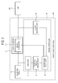
- FIG. 2 is a control block diagram of a power supply apparatus according to a first exemplary embodiment.
- the power supply apparatus 100 includes a solar cell module 10, a power converter 20 and a driving controller 30.
- the solar cell module 10 includes at least one solar cell to absorb sunlight, and outputs a direct current (DC) power from the absorbed sunlight.
- the solar cell included in the solar cell module 10 may be formed of semiconductor material, including but not limited to, amorphous silicon, monocrystalline silicon, polycrystalline silicon, and a compound semiconductor. Also, a plurality of solar cells may be connected in series and/or in parallel to constitute a solar cell array, thereby acquiring a predetermined voltage and/or current.
- the power converter 20 converts output from the solar cell module 10 and supplies the converted power to a load 200.
- the power converter 20 may include, but is not limited to, a voltage-fed self-excited inverter, or a DC-DC converter, which uses a self-extinction switching device.
- the switching device may include, but is not limited to, a gate turn-off thyristor, an insulated gate bipolar transistor, a power transistor, and a power metal oxide semiconductor field effect transistor (MOSFET).
- the converted power output (i.e., power, voltage, frequency, etc.) of the power converter 20 may be controlled by adjusting an on/off duty (hereinafter, referred to as a "duty ratio") of a gate pulse supplied to the switching device of the power converter 20 based on the converted power output from the power converter 20, which is described in greater detail below.
- a duty ratio an on/off duty
- the load 200 receives the power output from the power converter 20.
- the load may include, but is not limited to, a motor, a commercial AC system and combination thereof.
- the driving controller 30 measures the output of the solar cell module 10, for example, the DC power output, and controls the power converter 20 having a preset duty ratio to start operating in accordance with the measured output, which is discussed further below. Also, the driving controller 30 measures the output of the solar cell module 10, and controls the power converter 20 having a preset duty ratio to operate for a predetermined period of time corresponding to the measured output, which is also described in greater detail below.
- the driving controller 30 includes a solar cell module measuring unit 31, a driving time calculator 33, an output measuring unit 35, and a capacitor 37.
- the solar cell module measuring unit 31 determines DC power, i.e. voltage and/or current, output from the solar cell module 10. That is, based on the measured output voltage and current from the solar cell module 10, the solar cell module measuring unit 31 may calculate the output power.
- the driving controller 30 may preset a predetermined duty ratio to minimize electrical stress on the power converter 20 based on the measured output voltage and current determined by the cell module measuring unit 31. Thus, the driving controller 30 may control the power converter 20 to operating according to a predetermined duty ratio that is based on the measured output of the solar cell module 10.
- the driving time calculator 33 is in electrical communication with the solar cell module measuring unit 31 and the power converter 20 to control operation of the power converter 20 based on a calculated driving time. More specifically, the driving time calculator 33 calculates a predetermined period of time during which the power converter 20 operates, i.e., the driving time, on the basis of the output voltage and current measured by the solar cell module measuring unit 31, and outputs a driving control signal to drive the power converter 20, accordingly. Thus, the driving controller 30 may control the power converter 20 to be driven according to the calculated driving time.
- the driving controller 30 may previously set up a predetermined duty ratio to minimize electrical stress on the power converter 20 on the basis of the measured output voltage and current.
- the driving time calculator 33 may calculate a predetermined period of time, during which the power converter 20 operates, by taking the duty ratio into account in accordance with the output of the solar cell module 10.
- the measured output of the power converter 20 is communicated to the driving controller 30 as a feedback control signal.
- the output measuring unit 35 measures the output, for example a current output and/or a voltage output, from the power converter 20 to the load 200. Accordingly, the output measuring unit 35 outputs the measured output to the driving time calculator 33 as a feedback control signal.
- the driving controller 30 may control the power converter 20 having a predetermined duty ratio to start operating based on the feedback control signal.
- the driving controller 30 may operate the power converter 20 according to a predetermined duty ratio based on an output value obtained by subtracting the output of the power converter 20 measured by the output measuring unit 35 from the output measured by the solar cell module measuring unit 31.
- the driving controller 30 may control the power converter 20 to have a predetermined duty ratio, and it may drive the power converter 20 for a predetermined period of time in accordance with an output value obtained by subtracting the output of the power converter 20 measured by the output measuring unit 35 from the output measured by the solar cell module measuring unit 31. More specifically, the driving time calculator 33 may calculate a predetermined period of time, during which the power converter 20 operates, in consideration of the communicated output of the power converter 20, along with the measured output of the solar cell module 10. That is, a predetermined period of time over which the power converter 20 having the preset duty ratio is driven may be calculated on the basis of difference between the measured output of the solar cell module 10 and the communicated output of the power converter 20.
- the capacitor 37 is coupled between the solar cell module 10 and the solar cell module measuring unit, and receives the output from the solar cell module 10. Accordingly, the capacitor 37 is charged in response to the output of the solar cell module 10 to generate a charged voltage of the capacitor 37.
- the solar cell module measuring unit 31 measures the output of the solar cell module 10
- a charged voltage of the capacitor 37 may be measured.
- the measured value of the voltage charged in the capacitor 37 may be communicated to the driving time calculator 33. Accordingly, the driving time calculator 33 may calculate a period of time, during which the power converter 20 operates, on the basis of the measured value of the voltage charged in the capacitor 37 and/or the output value of the power converter 20 measured by the output measuring unit 35.
- the driving time calculator 33 may use the following expression to calculate a predetermined period of time AT over which the power converter 20 may be driven.
- V conv - V min 1 / C x I solar - I load ⁇ T
- V conv is a voltage input to the power converter 20
- V min is a voltage output from the power converter 20 to the load 200
- C is the capacitance of the capacitor 37
- I solar is a current output from the solar cell module
- I load is a current output from the power converter 20 to the load 200.
- the driving controller 30 in at least one exemplary embodiment previously calculates and sets up the period of time over which the power converter 20 is to be driven, thereby stably driving the power converter 20. Accordingly, as opposed to the conventional MPPT control method, there is no need for controlling the power converter 20 to track the maximum power point and continuously change the duty ratio, so that the power converter 20 may be driven with the minimum electrical stress.
- the power converter 20 and the driving controller 30 may be achieved by a digital circuit.
- the output measured by the solar cell module measuring unit 31 and the output measured by the output measuring unit 35 are converted into digital output values and input to the driving controller 30. If the converted digital output value is communicated to the driving time calculator 33 and the driving period of time is calculated, the driving controller 30 sets up the power converter 20 with the calculated driving period of time, thereby controlling the driving period of time of the power converter 20.
- FIG. 3 is a control block diagram of a power supply apparatus according to a second exemplary embodiment.
- the power supply apparatus of the second exemplary embodiment further includes a driving level calculator 39 instead of the driving time calculator 33 of the driving controller 30.
- the power converter 20 includes a driving comparator 21.
- the driving circuit 21 may comprise an analog circuit. Accordingly, except for the driving comparator 21 and the driving level calculator 39, the power supply apparatus of the second exemplary embodiment is similar to the first exemplary embodiment, and thus repetitive descriptions thereof will be avoided as necessary.
- the driving level calculator 39 determines a driving level of the power converter 20 in accordance with the output of the solar cell module 10 measured by the solar cell module measuring unit 31.
- the power to be converted by the power converter 20 is determined by taking the preset duty ratio into account in accordance with the measured output of the solar cell module.
- the driving level calculator 39 determines the power to be converted by the power converter 20. More specifically, the driving level calculator 39 takes into account the preset duty ratio by calculating a difference between the measured output of the solar cell module 10 and the output of the power converter 20 measured by the output measuring unit 35. Accordingly, the driving level calculator 39 outputs a driving level signal to the power converter 20 that indicates a driving level of the power converter 20. Thus, the driving controller 30 may control the power converter 20 to operate in accordance with the calculated driving level.
- the driving comparator 21 of the power converter 20 illustrated in FIG. 3 determines whether the power converter 20 is driven in accordance with the calculated driving level.
- the power converter 20 includes a capacitor (not shown) connected to one end of the driving comparator 21. If the power converter 20 receives a driving level calculated by the driving level calculator 39, the power converter 20 sets up a charging capacity of the capacitor (not shown) in accordance with the driving level.
- the power converter 20 converts power output from the solar cell module
- the current in the power converter 20 is charged in the capacitor.
- the driving comparator 21 compares the calculated driving level communicated from the driving level calculator 39 with a converted power level of the power converter 20. If the calculated driving level is equal to the converted power level, the power converter 20 stops operating. At this time, the charging completed capacitor realizes an open circuit, and the capacitor (not shown) is discharged. In response to the discharged output of the capacitor, an analog timer (not shown) connected to one end of the capacitor (not shown) is reset. Accordingly, the power converter 20 is controlled to operate during a predetermined period of time.
- the driving controller 30 may drive the power converter 20 within an acceptable range in accordance with the driving level calculated by the driving level calculator 39.
- FIG. 4 is a control block diagram of a power supply apparatus according to a third exemplary embodiment of the present invention.
- the driving controller 30 in the third exemplary embodiment of FIG. 4 is realized as an analog circuit.
- the power supply apparatus of the third exemplary embodiment illustrated in FIG. 4 is similar the second exemplary embodiment of FIG. 3 , and thus repetitive descriptions thereof will be avoided as necessary.
- Both the driving controller 30 and the power converter 20 in the third exemplary embodiment of FIG. 4 are achieved by analog circuits, so that they are different from the respective digital circuits of the first exemplary embodiment illustrated in FIG. 2 .
- the driving controller 30 measures an output current I and an output voltage V of the solar cell module 10, and communicates the measured outputs to a differential amplifying unit 32 via an analog amplifying unit 34.
- the differential amplifying unit 32 amplifies a difference between the output value received from the analog amplifying unit 34 and the output value of the power converter 20 received from the output measuring unit 35. Accordingly, an amplified result is communicated as a driving level to the driving comparator 21 of the power converter 20.
- the power converter 20 receiving the driving level operates in a similar manner to the power converter 20 described in the second exemplary embodiment of FIG. 2 .
- FIG. 5 illustrates an exemplary embodiment including a power converter that operates in the power supply apparatus according to the exemplary embodiments illustrated in FIGS. 2-4 .
- the maximum power point is tracked in accordance with incident solar energy in order to increase/decrease the duty ratio of the solar converter, thereby outputting power at the maximum power point.
- the solar converter With the rapid variation of the incident solar energy, the solar converter must rapidly increase or decrease its duty ratio in accordance with the incident solar energy, and thus the solar converter realizes undue electrical stress.
- diagrams "A” and “B” show examples of solar cell module outputs measured by the solar cell module measuring unit. That is, diagrams "A” and “B” show the difference between the output of the solar cell module and the output of the power converter 20, determined by the output measuring unit 35.
- A refers to the duty ratio of the power converter 20
- OT refers to a driving time of the power converter 20.
- the driving controller 30 may previously set up the duty ratio of the power converter 20.
- the driving time of the power converter 20 is calculated on the basis of the foregoing Expression 1 by taking the duty ratio into account in accordance with the output of the solar cell module, measured by the solar cell module measuring unit 31; or the difference between the output of the solar cell module and the output of the power converter 20, measured by the output measuring unit 35.
- the solar cell module output shown in diagram (A) is greater than the solar cell module output shown in diagram (B), measured by the solar cell module measuring unit 31.
- the difference between the output of the solar cell module and the output of the power converter 20, measured by the output measuring unit 35, is greater in diagram (A) than in diagram (B).
- the driving time ⁇ T of the power converter 20 in diagram (A) is longer than the driving time ⁇ T' of the power converter 20 in diagram (B).
- the power converter 20 having the preset duty ratio is varied during the driving time, so that the power converter 20 is significantly free from the electrical stress of the conventional solar converter, since the power converter 20 is driven by the preset duty ratio even though the incident solar energy and/or the load is largely varied.
- FIG. 6 is a schematic view of a power supply system according to an exemplary embodiment.
- the power supply system includes the power supply apparatus 100 and an electronic apparatus 300.
- the power supply apparatus 100 may include the power supply apparatuses 100 according to the exemplary embodiments illustrated in FIGS. 2-4 discussed in detail above.
- the electronic apparatus 300 includes a system unit 310 and a battery unit 320.
- the electronic apparatus 300 includes a chargeable battery, which may be any portable mobile electronic apparatus.
- various mobile electronic apparatuses may include a laptop computer, a personal computer such as a net-book computer, a mobile phone, a portable media player etc.
- the system unit 310 may perform various functions in accordance with the kind of electronic apparatus 300.
- the operation of the system unit 310 may include a plurality of system modes, including but not limited to, an operating mode, a normal mode and a standby mode.
- the operating mode all components such as a central processing unit (CPU) or the like included in the system unit 310 operate to thereby allow a user to use the functions of the electronic apparatus 300.
- the normal mode all components such as the CPU or the like of the system unit 310 are provided with power and are on standby to operate.
- the standby mode as a power protection mode of the electronic apparatus, only one or more components, such as the CPU, is supplied with power but the other components of the system unit are not supplied with the power.
- the operation mode consumes the most power, while the standby mode consumes the least power.
- the system unit 310 may serve as a load of the power supply apparatus 100.
- the system unit 310 communicates an operation state of the system unit 310 to the power supply apparatus 100. That is, information about whether the system unit 310 is in the operating mode, the normal mode or the standby mode may be communicated to the power supply apparatus 100.
- the battery unit 320 has a predetermined battery capacity to store energy, and is capable of supplying operation power to the system unit 310 if there is no commercial power supplied from the exterior.
- the system unit 310 may receive the operation power from at least one of the battery unit 320 and the power supply apparatus 100.
- the power supply apparatus 100 supplies the power output from the power converter 20 to the system unit 310.
- the output measuring unit 35 included in the driving controller 30 of the power supply apparatus 100 measures the output from the power converter 20 to the system unit 310, and communicates the measured output to the driving time calculator 33 or the driving level calculator 39.
- the solar cell module measuring unit 31 measures the output of the solar cell module, and communicates the measured output to the driving time calculator 33 or the driving level calculator 39.
- the driving time calculator 33 calculates the driving time of the power converter 20 by taking the preset duty ratio in accordance with the difference between the measured output of the solar cell module and the measured output of the power converter 20. Accordingly, the driving controller 30 drives the power converter 20 in accordance with the calculated driving time.
- the driving level calculator 39 calculates the power to be converted by the power converter 20 by taking the preset duty ratio in accordance with the difference between the measured output of the solar cell module and the measured output of the power converter 20. Accordingly, the driving level calculator 39 outputs a driving level signal to the power converter 20 that indicates a driving level of the power converter 20. Thus, the driving controller 30 may control the power converter 20 to operate in accordance with the calculated driving level.
- the driving time calculator 33 or the driving level calculator 39 may calculate the driving time or the driving level based on the measured value from the solar cell module measuring unit 31 and the output measuring unit 35 in real time.
- the driving controller 30 may more quickly calculate the driving time and/or the driving level on the basis of the output information of the power converter previously set corresponding to the information about the state of the system mode.
- a graph illustrates power supplied from a battery unit 320 and the power supply apparatus 100 to a system unit 310 of the power supply system of FIG. 6 .
- FIG. 7 illustrates a case where the power supplied from the power converter 20 in the power supply apparatus 100 does not satisfy the power necessary to operate the system unit 310 in all of the system modes, i.e., the operating mode, the normal mode and the standby mode.
- the system unit 310 receives the necessary power from both the power supply apparatus 100 and the battery unit 320.
- the power converted by the power converter 20 of the power supply apparatus 100 is most consumed by the system unit 310 when the system unit 310 is in the operating mode. At this time, an electric current quickly flows from the power converter 20 to the system unit 310, the driving time of the power converter 20 predicted by Expression 1 is shorter than those of the normal mode and the standby mode.
- the power is output to the system unit 310 and the battery unit 30 keeps outputting a predetermined first power level while the power is output from the power supply apparatus 100.
- the first power level may be a low power level.
- the second power level may be a high power level greater than the low power level.
- the system unit 310 may receive the power having a constant level regardless of the power output of the power supply apparatus 100.
- FIG. 8 is a control flowchart of the power supply apparatus according to exemplary embodiments illustrated in FIGS. 2-4 .
- the solar cell module measuring unit 31 measures the output of the solar cell module 10 (S12).
- the output from the power converter 20 to the load is measured by the output measuring unit 35 (S13).
- the measured output from the solar cell module 10 and the measured output from the power converter 20 are communicated to the driving controller 30, and the driving controller 30 calculates the time over which the power converter 20 having the preset duty ratio is driven in accordance with the difference between the measured output from the solar cell module 10 and the measured output from the power converter 20 (S14).
- the driving controller 30 controls the power converter 20 to operate during the calculated driving time (S15), and the power converted by the power converter 20 is output to a load (S16).
- FIG. 9 is a control flowchart of a power supply system according to at least one exemplary embodiment.
- the solar cell module measuring unit 31 measures the output of the solar cell module 10 (S22).
- the output from the power converter 20 to the electronic apparatus 300 is measured by the output measuring unit 35 (S23).
- the measured output from the solar cell module 10 and the measured output from the power converter 20 are communicated to the driving controller 30, and the driving controller 30 calculates the time over which the power converter 20 having the preset duty ratio is driven in accordance with the difference between the measured output from the solar cell module 10 and the measured output from the power converter 20 (S24).
- the driving controller 30 controls the power converter 20 to operate during the calculated driving time (S25), and the power converted by the power converter 20 is output to a load (S26).
- At least one of the power output from the power converter 20 and the power having a predetermined level output from the battery unit 320 of the electronic apparatus 300 is supplied to the system unit 310 of the electronic apparatus 300 (S27). In this case, if a predetermined driving time of the power converter 20 is terminated, the power having a predetermined level from only the battery 320 is supplied to the system unit 310.
- a power supply, a power supply system and a method of supplying power thereof in which a power converter to convert output from a solar cell is predicted and controlled by taking variation in the incident energy, load, etc. into account, thereby stably driving the power converter with the minimum electrical stress, avoiding noise due to voltage variation at an input terminal of the power converter, and avoiding additional design of a super-capacitor, a secondary battery, etc. necessary to store energy in order to provide against large variation of the incident solar energy at the input terminal of the conventional converter.
Landscapes
- Engineering & Computer Science (AREA)
- Power Engineering (AREA)
- Life Sciences & Earth Sciences (AREA)
- Sustainable Development (AREA)
- Sustainable Energy (AREA)
- Physics & Mathematics (AREA)
- Electromagnetism (AREA)
- General Physics & Mathematics (AREA)
- Radar, Positioning & Navigation (AREA)
- Automation & Control Theory (AREA)
- Control Of Electrical Variables (AREA)
- Charge And Discharge Circuits For Batteries Or The Like (AREA)
Abstract
Description
- The present invention relates to a power supply apparatus, a power supply system and a method of supplying power thereof, and more particularly, to a power supply apparatus, a power supply system and a method of supplying power thereof, in which sunlight is absorbed and converted into electric power, thereby supplying power.
- A conventional converter that converts electric power output from a solar cell of absorbing sunlight employs a control method for reducing a charging current in accordance with input power from the solar cell through maximum power point tracking (MPPT), so that power conversion can be performed by keeping the maximum available value, i.e., the maximum voltage of the output power from the solar cell. In a conventional MPPT, a maximum output occurs when a source resistance of the solar cell equals a load resistance of a load realized by the solar cell.
-
FIG. 1 is a graph showing power conversion based on the MPPT control, in which a dotted line indicates an electric current output from the solar cell and a solid line indicates an output voltage of the solar cell. Since power is the product of voltage and current, it is possible to find out the maximum power, as shown by line "A". Thus, it will be appreciated that current is decreased at a constant voltage Voc (open circuit voltage) when tracking a point of current decreased in accordance with incident energy of the solar cell. The MPPT control is a method of controlling the power to be always output at a maximum power point by measuring current and voltage at an output terminal of the solar cell, receiving the values of the measured current and voltage through an analog-digital converter (ADC), decreasing a duty ratio of the converter if the measured current and voltage are lower than the maximum power point, and increasing the duty ratio of the converter if the measured current and voltage are higher than the maximum power point. - However, if the incident energy to the solar cell is rapidly varied with rapid variation of sunshine, the conventional converter employing the MPPT control has to rapidly decrease/increase the duty ratio in order to output power at the maximum power point in accordance with the rapid variation of the incident energy. At this time, the converter is under undue electrical stress, and noise occurs due to voltage variation at an input terminal of the converter.
- To reduce the electrical stress on the converter due to rapid variation in the incident solar energy, an energy storage tank such as a lithium ion battery may be provided at the input terminal of the converter. However, if the incident solar energy exceeds the capacity of the energy storage tank, the same problem may arise as described above. Further, there is a shortcoming in that the energy storage tank is expensive. Also, there is a problem in that the conventional converter based on the MPPT control does not take into account any load variation.
- Accordingly, one or more exemplary embodiments of the present invention provide a power supply, a power supply system and a method of supplying power thereof, in which a converter to convert output from a solar cell is predicted and controlled by taking variation in incident solar energy, load, etc. into account, thereby stably driving the converter with the minimum electrical stress.
- Additional features and utilities of the present invention will be set forth in part in the description which follows and, in part, will be obvious from the description, or may be learned by practice of the present invention.
- The foregoing and/or other features may be achieved by providing a power supply apparatus including a solar cell module which includes at least one solar cell to absorb sunlight, a power converter which converts power output from the solar cell module and supplies the converted power to a load, and a driving controller which measures the output of the solar cell module and controls the power converter having a preset duty ratio to start operating in accordance with the measured output.
- The driving controller may control the power converter having the preset duty ratio to operate for a predetermined period of time in accordance with the measured output.
- The driving controller may include a solar cell module measuring unit to measure the output of the solar cell module.
- The driving controller may include a driving time calculator to calculate a driving time of the power converter in accordance with the output measured by the solar cell module measuring unit.
- The driving controller may include a capacitor to charge the output of the solar cell module, and the driving time calculator may calculate the driving time of the power converter in accordance with the charged capacity.
- The driving controller may include an output measuring unit to measure the output from the power converter to a load.
- The driving controller may include a driving time calculator to calculate a driving time of the power converter in accordance with difference between the charged output and the measured output of the power converter.
- The driving controller includes a capacitor to charge the output of the solar cell module, and the driving time calculator may calculate the driving time of the power converter in accordance with the charged output and the measured output of the power converter.
- The driving controller may include a driving level calculator to calculate a driving level of the power converter in accordance with the measured output of the solar cell module, and the power converter may include a driving comparator to compare whether the power converter is driven in accordance with the calculated driving level.
- The driving controller may include an output measuring unit to measure output from the power converter to a load, and the driving level calculator may calculate the driving level of the power converter in accordance with difference between the measured output from the solar cell module and the measured output from the power converter.
- The driving controller may include a capacitor to charge the output of the solar cell module, and the driving level calculator may calculate a driving level of the power converter in accordance with difference between the charged output and the measured output of the power converter.
- The power converter may include a direct current-direct current (DC-DC) converter.
- The driving controller may include a differential amplifying unit to amplify difference between the measured output of the solar cell module and the measured output of the power converter.
- According to another aspect of the present invention, there is provided a power supply system including a power supply apparatus which includes a solar cell module including at least one solar cell to absorb sunlight, a power converter converting power output from the solar cell module and supplying the converted power to an electronic apparatus, and a driving controller measuring the output of the solar cell module and controlling the power converter having a preset duty ratio to start operating in accordance with the measured output, and the electronic apparatus which includes a battery unit, and a system unit operating by receiving power having a predetermined level from at least one of the battery unit and the power supply apparatus.
- The driving controller may control the power converter having the preset duty ratio to operate for a predetermined period of time in accordance with the measured output.
- The system unit may receive the power having a predetermined level from only the battery unit when a predetermined driving time of the power converter is terminated.
- The driving controller may include a solar cell module measuring unit to measure the output of the solar cell module; and an output measuring unit to measure the output from the power converter to the electronic apparatus.
- The driving controller may include a driving time calculator to calculate a driving time of the power converter in accordance with difference between the measured output of the solar cell module and the measured output of the power converter.
- The driving controller may include a capacitor to charge the output of the solar cell module, and the driving time calculator may calculate the driving time of the power converter in accordance with difference between the charged capacity and the measured output of the power converter.
- The driving time calculator may receive information about a mode state of the system unit from the electronic apparatus, and calculates the driving time on the basis of preset output-information of the power converter with respect to the received information.
- The mode state of the system unit may include an operating mode, a normal mode and a standby mode.
- The driving controller may include a driving level calculator to calculate a driving level of the power converter in accordance with difference between the measured output of the solar cell module and the measured output of the power converter, and the power converter may include a driving comparator to compare whether the power converter is driven in accordance with the calculated driving level.
- The driving controller may include a capacitor to charge the output of the solar cell module, and the driving level calculator may calculate a driving level of the power converter in accordance with difference between the charged output and the measured output of the power converter.
- The driving level calculator may receive information about a mode state of the system unit from the electronic apparatus, and calculate the driving time on the basis of preset output-information of the power converter with respect to the received information.
- The mode state of the system unit may include an operating mode, a normal mode and a standby mode.
- The power converter may include a direct current-direct current (DC-DC) converter.
- The driving controller may include a differential amplifying unit to amplify difference between the measured output of the solar cell module and the measured output of the power converter.
- Still another feature may be achieved by providing a power supplying method of a power supply apparatus, the method including outputting power by absorbing sunlight from a solar cell module; measuring the output of the solar cell module, controlling a power converter having a preset duty ratio to start operating in accordance with the measured output, and supplying the converted power to a load.
- The controlling the power converter may include controlling the power converter having the preset duty ratio to operate for a predetermined period of time in accordance with the measured output.
- The method may further include calculating a driving time of the power converter in accordance with the measured output.
- The method may further include measuring the output from the power converter to the load.
- The calculating the driving time may include calculating the driving time of the power converter in accordance with difference between the measured output of the solar cell module and the measured output of the power converter.
- According to yet another aspect of the present invention, there isprovided a power supplying method of a power supply system, the method including, outputting power by absorbing sunlight from a solar cell module; measuring the output of the solar cell module, controlling a power converter having a preset duty ratio to start operating in accordance with the measured output; outputting power converted by the power converter to an electronic apparatus, and supplying a system unit of the electronic apparatus with power having a predetermined level from at least one of the power converter and a battery unit of the electronic apparatus.
- The controlling the power converter may include controlling the power converter having the preset duty ratio to operate for a predetermined period of time in accordance with the measured output.
- The supplying the system unit with power may include supplying the system unit with the power having a predetermined level from only the battery unit when a predetermined driving time of the power converter is terminated.
- The method may further include measuring the output from the power converter to the electronic apparatus.
- The method may further include calculating a driving time of the power converter in accordance with difference between the measured output of the solar cell module and the measured output of the power converter.
- The calculating the driving time may include receiving information about a mode state of the system unit from the electronic apparatus, and calculating the driving time on the basis of preset output-information of the power converter with respect to the received information.
- The mode state of the system unit may include an operating mode, a normal mode and a standby mode.
- According to another aspect of the present invention, there is provided a power supply apparatus including a power converter to output a converted power based on a solar cell output power, the power supply apparatus comprising a driving controller to determine the converted power output from the power converter and to control the operation of the power converter according to a preset duty ratio based on the determined converted power.
- According to yet another aspect of the present invention, there is provided a power supply apparatus to power a load comprising a power converter including a switching device operable in response to a gate pulse having a duty ratio to convert power from a solar cell into a converted power that is supplied to the load, and a driving controller to generate the gate pulse and to control the power converter by adjusting the duty ratio of the gate pulse based on the converted power output by the power converter.
- According to still another aspect of the present invention, there is provided a power supply apparatus comprising a solar cell module including at least one solar cell to absorb sunlight, a power converter to convert power output from the solar cell module and to supply the converted power to a load, and a driving controller to measure the output of the solar cell module and to operate the power converter according to a preset duty ratio over a predetermined period of time based on the measured output.
- The above and/or other features of the present invention will become apparent and more readily appreciated from the following description of the exemplary embodiments, taken in conjunction with the accompanying drawings, in which:
-
FIG. 1 illustrates a view of a conventional (maximum power point tracking (MPPT) control method; -
FIG. 2 is a control block diagram of a power supply apparatus according to a first exemplary embodiment; -
FIG. 3 is a control block diagram of a power supply apparatus according to a second exemplary embodiment; -
FIG. 4 is a control block diagram of a power supply apparatus according to a third exemplary embodiment; -
FIG. 5 illustrates an exemplary embodiment that a power converter operates in the power supply apparatus according to the first to third exemplary embodiment; -
FIG. 6 is a schematic view of a power supply system according to an exemplary embodiment; -
FIG. 7 is a graph showing power supplied from a battery unit and the power supply apparatus to a system unit in the power supply system ofFIG. 6 ; -
FIG. 8 is a control flowchart of the power supply apparatus according to the first to third exemplary embodiment; and -
FIG. 9 is a control flowchart of a power supply system according to an exemplary embodiment. - Reference will now be made in detail to exemplary embodiments of the present invention, examples of which are illustrated in the accompanying drawings, wherein like reference numerals refer to the like elements throughout.
- The exemplary embodiments are described below in order to explain the present invention by referring to the figures.
-
FIG. 2 is a control block diagram of a power supply apparatus according to a first exemplary embodiment. Thepower supply apparatus 100 includes asolar cell module 10, apower converter 20 and a drivingcontroller 30. - The
solar cell module 10 includes at least one solar cell to absorb sunlight, and outputs a direct current (DC) power from the absorbed sunlight. The solar cell included in thesolar cell module 10 may be formed of semiconductor material, including but not limited to, amorphous silicon, monocrystalline silicon, polycrystalline silicon, and a compound semiconductor. Also, a plurality of solar cells may be connected in series and/or in parallel to constitute a solar cell array, thereby acquiring a predetermined voltage and/or current. - The
power converter 20 converts output from thesolar cell module 10 and supplies the converted power to aload 200. - The
power converter 20 may include, but is not limited to, a voltage-fed self-excited inverter, or a DC-DC converter, which uses a self-extinction switching device. The switching device may include, but is not limited to, a gate turn-off thyristor, an insulated gate bipolar transistor, a power transistor, and a power metal oxide semiconductor field effect transistor (MOSFET). - The converted power output (i.e., power, voltage, frequency, etc.) of the
power converter 20 may be controlled by adjusting an on/off duty (hereinafter, referred to as a "duty ratio") of a gate pulse supplied to the switching device of thepower converter 20 based on the converted power output from thepower converter 20, which is described in greater detail below. - The
load 200 receives the power output from thepower converter 20. The load may include, but is not limited to, a motor, a commercial AC system and combination thereof. - The driving
controller 30 measures the output of thesolar cell module 10, for example, the DC power output, and controls thepower converter 20 having a preset duty ratio to start operating in accordance with the measured output, which is discussed further below. Also, the drivingcontroller 30 measures the output of thesolar cell module 10, and controls thepower converter 20 having a preset duty ratio to operate for a predetermined period of time corresponding to the measured output, which is also described in greater detail below. - More specifically, the driving
controller 30 includes a solar cellmodule measuring unit 31, a driving time calculator 33, anoutput measuring unit 35, and acapacitor 37. - The solar cell
module measuring unit 31 determines DC power, i.e. voltage and/or current, output from thesolar cell module 10. That is, based on the measured output voltage and current from thesolar cell module 10, the solar cellmodule measuring unit 31 may calculate the output power. - The driving
controller 30 may preset a predetermined duty ratio to minimize electrical stress on thepower converter 20 based on the measured output voltage and current determined by the cellmodule measuring unit 31. Thus, the drivingcontroller 30 may control thepower converter 20 to operating according to a predetermined duty ratio that is based on the measured output of thesolar cell module 10. - The driving time calculator 33 is in electrical communication with the solar cell
module measuring unit 31 and thepower converter 20 to control operation of thepower converter 20 based on a calculated driving time. More specifically, the driving time calculator 33 calculates a predetermined period of time during which thepower converter 20 operates, i.e., the driving time, on the basis of the output voltage and current measured by the solar cellmodule measuring unit 31, and outputs a driving control signal to drive thepower converter 20, accordingly. Thus, the drivingcontroller 30 may control thepower converter 20 to be driven according to the calculated driving time. - The driving
controller 30 may previously set up a predetermined duty ratio to minimize electrical stress on thepower converter 20 on the basis of the measured output voltage and current. Thus, the driving time calculator 33 may calculate a predetermined period of time, during which thepower converter 20 operates, by taking the duty ratio into account in accordance with the output of thesolar cell module 10. - The measured output of the
power converter 20 is communicated to the drivingcontroller 30 as a feedback control signal. Theoutput measuring unit 35 measures the output, for example a current output and/or a voltage output, from thepower converter 20 to theload 200. Accordingly, theoutput measuring unit 35 outputs the measured output to the driving time calculator 33 as a feedback control signal. - The driving
controller 30 may control thepower converter 20 having a predetermined duty ratio to start operating based on the feedback control signal. - More specifically, the driving
controller 30 may operate thepower converter 20 according to a predetermined duty ratio based on an output value obtained by subtracting the output of thepower converter 20 measured by theoutput measuring unit 35 from the output measured by the solar cellmodule measuring unit 31. - Also, the driving
controller 30 may control thepower converter 20 to have a predetermined duty ratio, and it may drive thepower converter 20 for a predetermined period of time in accordance with an output value obtained by subtracting the output of thepower converter 20 measured by theoutput measuring unit 35 from the output measured by the solar cellmodule measuring unit 31. More specifically, the driving time calculator 33 may calculate a predetermined period of time, during which thepower converter 20 operates, in consideration of the communicated output of thepower converter 20, along with the measured output of thesolar cell module 10. That is, a predetermined period of time over which thepower converter 20 having the preset duty ratio is driven may be calculated on the basis of difference between the measured output of thesolar cell module 10 and the communicated output of thepower converter 20. - Referring again to
FIG. 3 , thecapacitor 37 is coupled between thesolar cell module 10 and the solar cell module measuring unit, and receives the output from thesolar cell module 10. Accordingly, thecapacitor 37 is charged in response to the output of thesolar cell module 10 to generate a charged voltage of thecapacitor 37. Thus, when the solar cellmodule measuring unit 31 measures the output of thesolar cell module 10, a charged voltage of thecapacitor 37 may be measured. - The measured value of the voltage charged in the
capacitor 37 may be communicated to the driving time calculator 33. Accordingly, the driving time calculator 33 may calculate a period of time, during which thepower converter 20 operates, on the basis of the measured value of the voltage charged in thecapacitor 37 and/or the output value of thepower converter 20 measured by theoutput measuring unit 35. - Here, the driving time calculator 33 may use the following expression to calculate a predetermined period of time AT over which the
power converter 20 may be driven.
where Vconv is a voltage input to thepower converter 20, Vmin is a voltage output from thepower converter 20 to theload 200, C is the capacitance of thecapacitor 37, Isolar is a current output from the solar cell module, and Iload is a current output from thepower converter 20 to theload 200. - Thus, the driving
controller 30 in at least one exemplary embodiment previously calculates and sets up the period of time over which thepower converter 20 is to be driven, thereby stably driving thepower converter 20. Accordingly, as opposed to the conventional MPPT control method, there is no need for controlling thepower converter 20 to track the maximum power point and continuously change the duty ratio, so that thepower converter 20 may be driven with the minimum electrical stress. - In at least one exemplary embodiment, the
power converter 20 and the drivingcontroller 30 may be achieved by a digital circuit. The output measured by the solar cellmodule measuring unit 31 and the output measured by theoutput measuring unit 35 are converted into digital output values and input to the drivingcontroller 30. If the converted digital output value is communicated to the driving time calculator 33 and the driving period of time is calculated, the drivingcontroller 30 sets up thepower converter 20 with the calculated driving period of time, thereby controlling the driving period of time of thepower converter 20. -
FIG. 3 is a control block diagram of a power supply apparatus according to a second exemplary embodiment. - As compared with the power supply apparatus of the first exemplary embodiment, the power supply apparatus of the second exemplary embodiment further includes a
driving level calculator 39 instead of the driving time calculator 33 of the drivingcontroller 30. Further, thepower converter 20 includes a drivingcomparator 21. In at least one exemplary embodiment, the drivingcircuit 21 may comprise an analog circuit. Accordingly, except for the drivingcomparator 21 and thedriving level calculator 39, the power supply apparatus of the second exemplary embodiment is similar to the first exemplary embodiment, and thus repetitive descriptions thereof will be avoided as necessary. - Referring to
FIG. 3 , thedriving level calculator 39 determines a driving level of thepower converter 20 in accordance with the output of thesolar cell module 10 measured by the solar cellmodule measuring unit 31. - The power to be converted by the
power converter 20 is determined by taking the preset duty ratio into account in accordance with the measured output of the solar cell module. - Also, the
driving level calculator 39 determines the power to be converted by thepower converter 20. More specifically, thedriving level calculator 39 takes into account the preset duty ratio by calculating a difference between the measured output of thesolar cell module 10 and the output of thepower converter 20 measured by theoutput measuring unit 35. Accordingly, thedriving level calculator 39 outputs a driving level signal to thepower converter 20 that indicates a driving level of thepower converter 20. Thus, the drivingcontroller 30 may control thepower converter 20 to operate in accordance with the calculated driving level. - The driving
comparator 21 of thepower converter 20 illustrated inFIG. 3 determines whether thepower converter 20 is driven in accordance with the calculated driving level. - More specifically, according to at least one exemplary embodiment illustrated in
FIG. 3 , thepower converter 20 includes a capacitor (not shown) connected to one end of the drivingcomparator 21. If thepower converter 20 receives a driving level calculated by thedriving level calculator 39, thepower converter 20 sets up a charging capacity of the capacitor (not shown) in accordance with the driving level. - While the
power converter 20 converts power output from the solar cell module, the current in thepower converter 20 is charged in the capacitor. When the electric charging level of the capacitor reaches a preset capacity, the drivingcomparator 21 compares the calculated driving level communicated from thedriving level calculator 39 with a converted power level of thepower converter 20. If the calculated driving level is equal to the converted power level, thepower converter 20 stops operating. At this time, the charging completed capacitor realizes an open circuit, and the capacitor (not shown) is discharged. In response to the discharged output of the capacitor, an analog timer (not shown) connected to one end of the capacitor (not shown) is reset. Accordingly, thepower converter 20 is controlled to operate during a predetermined period of time. - In the power supply apparatus according to at least one exemplary embodiment, the driving
controller 30 may drive thepower converter 20 within an acceptable range in accordance with the driving level calculated by thedriving level calculator 39. -
FIG. 4 is a control block diagram of a power supply apparatus according to a third exemplary embodiment of the present invention. - As opposed to the power supply apparatus of the second exemplary embodiment illustrated in
FIG. 3 , the drivingcontroller 30 in the third exemplary embodiment ofFIG. 4 is realized as an analog circuit. Besides providing the drivingcontroller 30 as an analog circuit, the power supply apparatus of the third exemplary embodiment illustrated inFIG. 4 is similar the second exemplary embodiment ofFIG. 3 , and thus repetitive descriptions thereof will be avoided as necessary. Both the drivingcontroller 30 and thepower converter 20 in the third exemplary embodiment ofFIG. 4 are achieved by analog circuits, so that they are different from the respective digital circuits of the first exemplary embodiment illustrated inFIG. 2 . - In this exemplary embodiment, the driving
controller 30 measures an output current I and an output voltage V of thesolar cell module 10, and communicates the measured outputs to adifferential amplifying unit 32 via ananalog amplifying unit 34. The output value from thepower converter 20 to theload 200, measured by theoutput measuring unit 35, is communicated to thedifferential amplifying unit 32. - The
differential amplifying unit 32 amplifies a difference between the output value received from theanalog amplifying unit 34 and the output value of thepower converter 20 received from theoutput measuring unit 35. Accordingly, an amplified result is communicated as a driving level to the drivingcomparator 21 of thepower converter 20. Thepower converter 20 receiving the driving level operates in a similar manner to thepower converter 20 described in the second exemplary embodiment ofFIG. 2 . -
FIG. 5 illustrates an exemplary embodiment including a power converter that operates in the power supply apparatus according to the exemplary embodiments illustrated inFIGS. 2-4 . - In a solar converter employing a conventional MPPT control method, the maximum power point is tracked in accordance with incident solar energy in order to increase/decrease the duty ratio of the solar converter, thereby outputting power at the maximum power point.
- With the rapid variation of the incident solar energy, the solar converter must rapidly increase or decrease its duty ratio in accordance with the incident solar energy, and thus the solar converter realizes undue electrical stress.
- However, the
power converter 20 shown inFIG. 5 reduces the electrical stress on the solar converter, similar to the exemplary embodiments illustrated inFIGS. 2-4 . Referring toFIG. 5 , diagrams "A" and "B" show examples of solar cell module outputs measured by the solar cell module measuring unit. That is, diagrams "A" and "B" show the difference between the output of the solar cell module and the output of thepower converter 20, determined by theoutput measuring unit 35. - In
FIG. 5 , "A" refers to the duty ratio of thepower converter 20, and "OT" refers to a driving time of thepower converter 20. - The driving
controller 30 may previously set up the duty ratio of thepower converter 20. Thus, the driving time of thepower converter 20 is calculated on the basis of the foregoing Expression 1 by taking the duty ratio into account in accordance with the output of the solar cell module, measured by the solar cellmodule measuring unit 31; or the difference between the output of the solar cell module and the output of thepower converter 20, measured by theoutput measuring unit 35. - Referring further to
FIG. 5 , the solar cell module output shown in diagram (A) is greater than the solar cell module output shown in diagram (B), measured by the solar cellmodule measuring unit 31. Put another way, the difference between the output of the solar cell module and the output of thepower converter 20, measured by theoutput measuring unit 35, is greater in diagram (A) than in diagram (B). As shown inFIG. 5 , it is be appreciated that the driving time ΔT of thepower converter 20 in diagram (A) is longer than the driving time ΔT' of thepower converter 20 in diagram (B). - Therefore, the
power converter 20 having the preset duty ratio is varied during the driving time, so that thepower converter 20 is significantly free from the electrical stress of the conventional solar converter, since thepower converter 20 is driven by the preset duty ratio even though the incident solar energy and/or the load is largely varied. -
FIG. 6 is a schematic view of a power supply system according to an exemplary embodiment. - The power supply system includes the
power supply apparatus 100 and anelectronic apparatus 300. - The
power supply apparatus 100 may include thepower supply apparatuses 100 according to the exemplary embodiments illustrated inFIGS. 2-4 discussed in detail above. - The
electronic apparatus 300 includes asystem unit 310 and abattery unit 320. - The
electronic apparatus 300 includes a chargeable battery, which may be any portable mobile electronic apparatus. For example, various mobile electronic apparatuses may include a laptop computer, a personal computer such as a net-book computer, a mobile phone, a portable media player etc. - The
system unit 310 may perform various functions in accordance with the kind ofelectronic apparatus 300. The operation of thesystem unit 310 may include a plurality of system modes, including but not limited to, an operating mode, a normal mode and a standby mode. In the operating mode, all components such as a central processing unit (CPU) or the like included in thesystem unit 310 operate to thereby allow a user to use the functions of theelectronic apparatus 300. In the normal mode, all components such as the CPU or the like of thesystem unit 310 are provided with power and are on standby to operate. In the standby mode, as a power protection mode of the electronic apparatus, only one or more components, such as the CPU, is supplied with power but the other components of the system unit are not supplied with the power. Regarding the power consumption with respect to each system mode described above, the operation mode consumes the most power, while the standby mode consumes the least power. Thesystem unit 310 may serve as a load of thepower supply apparatus 100. - The
system unit 310 communicates an operation state of thesystem unit 310 to thepower supply apparatus 100. That is, information about whether thesystem unit 310 is in the operating mode, the normal mode or the standby mode may be communicated to thepower supply apparatus 100. - The
battery unit 320 has a predetermined battery capacity to store energy, and is capable of supplying operation power to thesystem unit 310 if there is no commercial power supplied from the exterior. - Thus, the
system unit 310 may receive the operation power from at least one of thebattery unit 320 and thepower supply apparatus 100. - The
power supply apparatus 100 supplies the power output from thepower converter 20 to thesystem unit 310. - Accordingly, the
output measuring unit 35 included in the drivingcontroller 30 of thepower supply apparatus 100 measures the output from thepower converter 20 to thesystem unit 310, and communicates the measured output to the driving time calculator 33 or thedriving level calculator 39. - Also, the solar cell
module measuring unit 31 measures the output of the solar cell module, and communicates the measured output to the driving time calculator 33 or thedriving level calculator 39. - The driving time calculator 33 calculates the driving time of the
power converter 20 by taking the preset duty ratio in accordance with the difference between the measured output of the solar cell module and the measured output of thepower converter 20. Accordingly, the drivingcontroller 30 drives thepower converter 20 in accordance with the calculated driving time. - The
driving level calculator 39 calculates the power to be converted by thepower converter 20 by taking the preset duty ratio in accordance with the difference between the measured output of the solar cell module and the measured output of thepower converter 20. Accordingly, thedriving level calculator 39 outputs a driving level signal to thepower converter 20 that indicates a driving level of thepower converter 20. Thus, the drivingcontroller 30 may control thepower converter 20 to operate in accordance with the calculated driving level. - As described above, the driving time calculator 33 or the
driving level calculator 39 may calculate the driving time or the driving level based on the measured value from the solar cellmodule measuring unit 31 and theoutput measuring unit 35 in real time. - Alternatively, if the
system unit 310 communicates information about a system mode of thepower supply apparatus 100, the drivingcontroller 30 may more quickly calculate the driving time and/or the driving level on the basis of the output information of the power converter previously set corresponding to the information about the state of the system mode. - Referring to
FIG. 7 , a graph illustrates power supplied from abattery unit 320 and thepower supply apparatus 100 to asystem unit 310 of the power supply system ofFIG. 6 . - More specifically,
FIG. 7 illustrates a case where the power supplied from thepower converter 20 in thepower supply apparatus 100 does not satisfy the power necessary to operate thesystem unit 310 in all of the system modes, i.e., the operating mode, the normal mode and the standby mode. Thus, thesystem unit 310 receives the necessary power from both thepower supply apparatus 100 and thebattery unit 320. - The power converted by the
power converter 20 of thepower supply apparatus 100 is most consumed by thesystem unit 310 when thesystem unit 310 is in the operating mode. At this time, an electric current quickly flows from thepower converter 20 to thesystem unit 310, the driving time of thepower converter 20 predicted by Expression 1 is shorter than those of the normal mode and the standby mode. - During the driving time of the
power supply apparatus 100, the power is output to thesystem unit 310 and thebattery unit 30 keeps outputting a predetermined first power level while the power is output from thepower supply apparatus 100. The first power level may be a low power level. - However, if the driving time of the
power converter 20 is terminated and thepower converter 20 suspends operating, there is no output from thepower converter 20 to thesystem unit 310. In this case, the power output from thebattery unit 320 is changed to have a second power level necessary to operate thesystem unit 310. - The second power level may be a high power level greater than the low power level.
- Thus, the
system unit 310 may receive the power having a constant level regardless of the power output of thepower supply apparatus 100. -
FIG. 8 is a control flowchart of the power supply apparatus according to exemplary embodiments illustrated inFIGS. 2-4 . - When a solar cell absorbs sunlight and the
solar cell module 10 outputs power (S11), the solar cellmodule measuring unit 31 measures the output of the solar cell module 10 (S12). - Also, the output from the
power converter 20 to the load is measured by the output measuring unit 35 (S13). - The measured output from the
solar cell module 10 and the measured output from thepower converter 20 are communicated to the drivingcontroller 30, and the drivingcontroller 30 calculates the time over which thepower converter 20 having the preset duty ratio is driven in accordance with the difference between the measured output from thesolar cell module 10 and the measured output from the power converter 20 (S14). - The driving
controller 30 controls thepower converter 20 to operate during the calculated driving time (S15), and the power converted by thepower converter 20 is output to a load (S16). -
FIG. 9 is a control flowchart of a power supply system according to at least one exemplary embodiment. - When a solar cell absorbs sunlight and the
solar cell module 10 outputs power (S21), the solar cellmodule measuring unit 31 measures the output of the solar cell module 10 (S22). - Also, the output from the
power converter 20 to theelectronic apparatus 300 is measured by the output measuring unit 35 (S23). - The measured output from the
solar cell module 10 and the measured output from thepower converter 20 are communicated to the drivingcontroller 30, and the drivingcontroller 30 calculates the time over which thepower converter 20 having the preset duty ratio is driven in accordance with the difference between the measured output from thesolar cell module 10 and the measured output from the power converter 20 (S24). - The driving
controller 30 controls thepower converter 20 to operate during the calculated driving time (S25), and the power converted by thepower converter 20 is output to a load (S26). - At least one of the power output from the
power converter 20 and the power having a predetermined level output from thebattery unit 320 of theelectronic apparatus 300 is supplied to thesystem unit 310 of the electronic apparatus 300 (S27). In this case, if a predetermined driving time of thepower converter 20 is terminated, the power having a predetermined level from only thebattery 320 is supplied to thesystem unit 310. - As described above, there are provided a power supply, a power supply system and a method of supplying power thereof, in which a power converter to convert output from a solar cell is predicted and controlled by taking variation in the incident energy, load, etc. into account, thereby stably driving the power converter with the minimum electrical stress, avoiding noise due to voltage variation at an input terminal of the power converter, and avoiding additional design of a super-capacitor, a secondary battery, etc. necessary to store energy in order to provide against large variation of the incident solar energy at the input terminal of the conventional converter.
- Although a few exemplary embodiments have been shown and described, it will be appreciated by those skilled in the art that changes may be made in these exemplary embodiments without departing from the invention, the scope of which is defined in the appended claims.
Claims (15)
- A power supply apparatus comprising:a solar cell module including at least one solar cell to absorb sunlight;a power converter to convert power output from the solar cell module and to supply the converted power to a load; anda driving controller to measure the output of the solar cell module and to control the power converter having a preset duty ratio to start operating for a predetermined period of time based on the measured output.
- The power supply apparatus according to claim 1, wherein the driving controller comprises a solar cell module measuring unit to measure the output of the solar cell module.
- The power supply apparatus according to claim 2, wherein the driving controller comprises a driving time calculator to calculate a driving time of the power converter based on the output measured by the solar cell module measuring unit.
- The power supply apparatus according to claim 3, wherein the driving controller comprises a capacitor to charge in response to the output of the solar cell module to generate a charged voltage, and
the driving time calculator calculates the driving time of the power converter based on the charged voltage of the capacitor. - The power supply apparatus according to claim 2, wherein the driving controller comprises an output measuring unit to measure the output from the power converter to a load.
- The power supply apparatus according to claim 5, wherein the driving controller comprises a driving time calculator to calculate a driving time of the power converter based on a difference between the charged voltage of the capacitor and the measured output of the power converter.
- The power supply apparatus according to claim 6, wherein the driving controller comprises a capacitor to charge in response to the output of the solar cell module to generate a charged voltage, and
wherein the driving time calculator calculates the driving time of the power converter based on the charged voltage of the capacitor and the measured output of the power converter. - The power supply apparatus according to claim 2, wherein the driving controller comprises a driving level calculator to calculate a driving level of the power converter based on the measured output of the solar cell module, and
wherein the power converter comprises a driving comparator to compare whether the power converter is driven based on the calculated driving level. - The power supply apparatus according to claim 8, wherein the driving controller comprises an output measuring unit to measure an output from the power converter to a load, and
the driving level calculator calculates the driving level of the power converter based on a difference between the measured output from the solar cell module and the measured output from the power converter. - The power supply apparatus according to claim 9, wherein the driving controller comprises a capacitor to charge in response to the output of the solar cell module, and
the driving level calculator calculates a driving level of the power converter based on a difference between the charged voltage of the capacitor and the measured output of the power converter. - The power supply apparatus according to claim 1, wherein the power converter comprises a direct current (DC)-direct current (DC) converter.
- The power supply apparatus according to claim 5, wherein the driving controller comprises a differential amplifying unit to amplify a difference between the measured output of the solar cell module and the measured output of the power converter.
- A power supply system comprising:a power supply apparatus including a solar cell module having at least one solar cell to absorb sunlight;a power converter to convert power output from the solar cell module and to supply the converted power to an electronic apparatus; anda driving controller to measure the output of the solar cell module and to control the power converter having a preset duty ratio to start operating based on the measured output,wherein the electronic apparatus comprises:a battery unit; anda system unit to operate in response to receiving power having a predetermined level from at least one of the battery unit and the power supply apparatus.
- The power supply system according to claim 13, wherein the system unit receives the power having a predetermined level from only the battery unit when a predetermined driving time of the power converter is terminated.
- The power supply system according to claim 14, wherein the driving controller receives information about a mode state of the system unit from the electronic apparatus, and calculates the driving time on the basis of preset output-information of the power converter with respect to the received information, and
wherein the mode state of the system unit comprises an operating mode, a normal mode and a standby mode.
Applications Claiming Priority (1)
| Application Number | Priority Date | Filing Date | Title |
|---|---|---|---|
| KR1020100095781A KR101727521B1 (en) | 2010-10-01 | 2010-10-01 | Power supply apparatus, power supply system and method of supplying power thereof |
Publications (3)
| Publication Number | Publication Date |
|---|---|
| EP2437373A2 true EP2437373A2 (en) | 2012-04-04 |
| EP2437373A3 EP2437373A3 (en) | 2016-09-07 |
| EP2437373B1 EP2437373B1 (en) | 2019-03-06 |
Family
ID=45470239
Family Applications (1)
| Application Number | Title | Priority Date | Filing Date |
|---|---|---|---|
| EP11172602.2A Not-in-force EP2437373B1 (en) | 2010-10-01 | 2011-07-04 | Power supply apparatus, power supply system and method of supplying power thereof |
Country Status (3)
| Country | Link |
|---|---|
| US (1) | US9647488B2 (en) |
| EP (1) | EP2437373B1 (en) |
| KR (1) | KR101727521B1 (en) |
Cited By (1)
| Publication number | Priority date | Publication date | Assignee | Title |
|---|---|---|---|---|
| CN104267778A (en) * | 2014-09-17 | 2015-01-07 | 河海大学常州校区 | Power integral-based maximum power point tracking method for photo-voltaic power generation |
Families Citing this family (9)
| Publication number | Priority date | Publication date | Assignee | Title |
|---|---|---|---|---|
| US8466582B2 (en) * | 2010-12-03 | 2013-06-18 | Enphase Energy, Inc. | Method and apparatus for applying an electric field to a photovoltaic element |
| US8988096B1 (en) * | 2011-03-06 | 2015-03-24 | Sunpower Corporation | Flash testing of photovoltaic modules with integrated electronics |
| US9459139B2 (en) * | 2011-09-06 | 2016-10-04 | Morgan Solar Inc. | Photovoltaic generating system with control unit for controlling output power conversion and actuation of photovoltaic tracker units |
| US20130181692A1 (en) * | 2012-01-12 | 2013-07-18 | Ritek Corporation | Power supply system |
| US8988030B2 (en) * | 2012-11-13 | 2015-03-24 | Schlumberger Technology Corporation | Power control for electrical applications over long cables |
| RU2550360C1 (en) * | 2013-12-03 | 2015-05-10 | Федеральное государственное бюджетное образовательное учреждение высшего профессионального образования "Нижегородский государственный технический университет им. Р.Е. Алексеева", НГТУ | Method of load supply from solar battery |
| US11205900B2 (en) * | 2019-01-14 | 2021-12-21 | Samsung Electronics Co., Ltd. | Device and method with power control |
| RU2721476C1 (en) * | 2019-03-19 | 2020-05-19 | Акционерное общество "Авиационная электроника и коммуникационные системы" (АО "АВЭКС") | Method of pulse stabilization of direct voltage on load of solar generator |
| KR102245969B1 (en) * | 2019-11-21 | 2021-04-29 | 연세대학교 산학협력단 | System and Method for Controlling Constant Power Generation of Photovoltaic System |
Family Cites Families (12)
| Publication number | Priority date | Publication date | Assignee | Title |
|---|---|---|---|---|
| JP3382434B2 (en) | 1995-09-22 | 2003-03-04 | キヤノン株式会社 | Battery power supply voltage control device and voltage control method |
| CA2403725A1 (en) | 2000-03-22 | 2001-09-27 | The Board Of Trustees Of The University Of Illinois | Oscillatorless dc-dc power converter |
| US6586887B1 (en) * | 2002-03-06 | 2003-07-01 | Hitachi High-Technologies Corporation | High-frequency power supply apparatus for plasma generation apparatus |
| FR2843464B1 (en) * | 2002-08-09 | 2006-09-08 | Cit Alcatel | CIRCUIT FOR CONDITIONING A SOURCE AT THE MAXIMUM POWER POINT |
| CN1820405A (en) * | 2003-07-10 | 2006-08-16 | 皇家飞利浦电子股份有限公司 | Switched mode power supply |
| JP4719434B2 (en) * | 2004-07-22 | 2011-07-06 | 長野日本無線株式会社 | Solar cell power generator |
| CN101495924B (en) * | 2006-07-27 | 2011-07-27 | 西铁城控股株式会社 | Electronic device |
| TWI331264B (en) * | 2006-12-26 | 2010-10-01 | Richtek Technology Corp | Analog photovoltaic power circuit |
| KR100994806B1 (en) | 2008-02-01 | 2010-11-17 | 엘지전자 주식회사 | Power management controller of the system and its control method |
| JP2010034108A (en) * | 2008-07-25 | 2010-02-12 | Daido Gakuen | Cooling device and cooling method for solar cell panel |
| US8629658B1 (en) * | 2009-12-22 | 2014-01-14 | Linear Technology Corporation | Method and system for solar panel peak-power transfer using input voltage regulation |
| US8803489B2 (en) * | 2010-07-16 | 2014-08-12 | Virginia Tech Intellectual Properties, Inc. | Adaptive on-time control for power factor correction stage light load efficiency |
-
2010
- 2010-10-01 KR KR1020100095781A patent/KR101727521B1/en not_active Expired - Fee Related
-
2011
- 2011-07-04 EP EP11172602.2A patent/EP2437373B1/en not_active Not-in-force
- 2011-09-09 US US13/228,862 patent/US9647488B2/en not_active Expired - Fee Related
Non-Patent Citations (1)
| Title |
|---|
| None |
Cited By (2)
| Publication number | Priority date | Publication date | Assignee | Title |
|---|---|---|---|---|
| CN104267778A (en) * | 2014-09-17 | 2015-01-07 | 河海大学常州校区 | Power integral-based maximum power point tracking method for photo-voltaic power generation |
| CN104267778B (en) * | 2014-09-17 | 2016-02-10 | 河海大学常州校区 | A kind of photovoltaic maximum power point tracking based on power differential |
Also Published As
| Publication number | Publication date |
|---|---|
| US9647488B2 (en) | 2017-05-09 |
| KR20120034313A (en) | 2012-04-12 |
| KR101727521B1 (en) | 2017-04-17 |
| EP2437373B1 (en) | 2019-03-06 |
| EP2437373A3 (en) | 2016-09-07 |
| US20120081088A1 (en) | 2012-04-05 |
Similar Documents
| Publication | Publication Date | Title |
|---|---|---|
| EP2437373B1 (en) | Power supply apparatus, power supply system and method of supplying power thereof | |
| CN102088244B (en) | Maximum power point tracking converter and maximum power point tracking method | |
| US9413185B2 (en) | Energy storage device and method for controlling the same | |
| JP3986503B2 (en) | Circuit structures, additional modules, and solar equipment systems | |
| US8901889B2 (en) | Discharge control apparatus and discharge control method | |
| US20100244573A1 (en) | Hybrid power delivery system and method | |
| US20120187897A1 (en) | Battery charger for use with low voltage energy harvesting device | |
| US20130049673A1 (en) | Photo-voltaic array fed switched capacitor dc-dc converter based battery charging for li-ion batteries | |
| EP1528654A1 (en) | Circuit for battery/capacitor power source | |
| US20080036432A1 (en) | Power supply device | |
| JP2002369407A (en) | Backup power supply with peak cut function | |
| JP2012191838A (en) | Battery pack, electric tool, adapter for connecting battery pack and electric tool, and electric tool system | |
| WO2013118336A1 (en) | Power conversion device | |
| KR20060047861A (en) | Power supply and control method used for the power supply | |
| US20140253014A1 (en) | Charging control device, solar power generation system and charging control method | |
| JP2011250608A (en) | Solar cell system | |
| US9473041B2 (en) | Switching power supply apparatus with improved power conversion efficency to reduce power usage | |
| US10063090B2 (en) | Solar power generation device and control method of solar power generation device | |
| JP2009207239A (en) | Charging controller for solar cells | |
| US20130285476A1 (en) | Power supply device, inverter device, power tool | |
| WO2018138710A1 (en) | Dc power supply system | |
| US9559538B1 (en) | Switch mode battery charger with improved battery charging time | |
| CN113507135B (en) | Energy conversion system and method for photovoltaic power generation system | |
| JP2007335373A (en) | Fuel cell system | |
| JP2011211812A (en) | Power unit |
Legal Events
| Date | Code | Title | Description |
|---|---|---|---|
| PUAI | Public reference made under article 153(3) epc to a published international application that has entered the european phase |
Free format text: ORIGINAL CODE: 0009012 |
|
| AK | Designated contracting states |
Kind code of ref document: A2 Designated state(s): AL AT BE BG CH CY CZ DE DK EE ES FI FR GB GR HR HU IE IS IT LI LT LU LV MC MK MT NL NO PL PT RO RS SE SI SK SM TR |
|
| AX | Request for extension of the european patent |
Extension state: BA ME |
|
| RAP1 | Party data changed (applicant data changed or rights of an application transferred) |
Owner name: SAMSUNG ELECTRONICS CO., LTD. |
|
| PUAL | Search report despatched |
Free format text: ORIGINAL CODE: 0009013 |
|
| AK | Designated contracting states |
Kind code of ref document: A3 Designated state(s): AL AT BE BG CH CY CZ DE DK EE ES FI FR GB GR HR HU IE IS IT LI LT LU LV MC MK MT NL NO PL PT RO RS SE SI SK SM TR |
|
| AX | Request for extension of the european patent |
Extension state: BA ME |
|
| RIC1 | Information provided on ipc code assigned before grant |
Ipc: H02J 7/34 20060101AFI20160729BHEP Ipc: H02J 7/35 20060101ALI20160729BHEP |
|
| STAA | Information on the status of an ep patent application or granted ep patent |
Free format text: STATUS: REQUEST FOR EXAMINATION WAS MADE |
|
| 17P | Request for examination filed |
Effective date: 20161130 |
|
| RBV | Designated contracting states (corrected) |
Designated state(s): AL AT BE BG CH CY CZ DE DK EE ES FI FR GB GR HR HU IE IS IT LI LT LU LV MC MK MT NL NO PL PT RO RS SE SI SK SM TR |
|
| STAA | Information on the status of an ep patent application or granted ep patent |
Free format text: STATUS: EXAMINATION IS IN PROGRESS |
|
| 17Q | First examination report despatched |
Effective date: 20170906 |
|
| GRAP | Despatch of communication of intention to grant a patent |
Free format text: ORIGINAL CODE: EPIDOSNIGR1 |
|
| STAA | Information on the status of an ep patent application or granted ep patent |
Free format text: STATUS: GRANT OF PATENT IS INTENDED |
|
| RIC1 | Information provided on ipc code assigned before grant |
Ipc: G05F 1/67 20060101ALN20180829BHEP Ipc: H02J 7/34 20060101AFI20180829BHEP Ipc: H02J 7/35 20060101ALI20180829BHEP |
|
| INTG | Intention to grant announced |
Effective date: 20180913 |
|
| GRAS | Grant fee paid |
Free format text: ORIGINAL CODE: EPIDOSNIGR3 |
|
| GRAA | (expected) grant |
Free format text: ORIGINAL CODE: 0009210 |
|
| STAA | Information on the status of an ep patent application or granted ep patent |
Free format text: STATUS: THE PATENT HAS BEEN GRANTED |
|
| RAP1 | Party data changed (applicant data changed or rights of an application transferred) |
Owner name: SAMSUNG ELECTRONICS CO., LTD. |
|
| AK | Designated contracting states |
Kind code of ref document: B1 Designated state(s): AL AT BE BG CH CY CZ DE DK EE ES FI FR GB GR HR HU IE IS IT LI LT LU LV MC MK MT NL NO PL PT RO RS SE SI SK SM TR |
|
| REG | Reference to a national code |
Ref country code: GB Ref legal event code: FG4D |
|
| REG | Reference to a national code |
Ref country code: CH Ref legal event code: EP Ref country code: AT Ref legal event code: REF Ref document number: 1105860 Country of ref document: AT Kind code of ref document: T Effective date: 20190315 |
|
| REG | Reference to a national code |
Ref country code: DE Ref legal event code: R096 Ref document number: 602011056805 Country of ref document: DE |
|
| REG | Reference to a national code |
Ref country code: IE Ref legal event code: FG4D |
|
| REG | Reference to a national code |
Ref country code: NL Ref legal event code: FP |
|
| REG | Reference to a national code |
Ref country code: LT Ref legal event code: MG4D |
|
| PG25 | Lapsed in a contracting state [announced via postgrant information from national office to epo] |
Ref country code: SE Free format text: LAPSE BECAUSE OF FAILURE TO SUBMIT A TRANSLATION OF THE DESCRIPTION OR TO PAY THE FEE WITHIN THE PRESCRIBED TIME-LIMIT Effective date: 20190306 Ref country code: NO Free format text: LAPSE BECAUSE OF FAILURE TO SUBMIT A TRANSLATION OF THE DESCRIPTION OR TO PAY THE FEE WITHIN THE PRESCRIBED TIME-LIMIT Effective date: 20190606 Ref country code: FI Free format text: LAPSE BECAUSE OF FAILURE TO SUBMIT A TRANSLATION OF THE DESCRIPTION OR TO PAY THE FEE WITHIN THE PRESCRIBED TIME-LIMIT Effective date: 20190306 Ref country code: LT Free format text: LAPSE BECAUSE OF FAILURE TO SUBMIT A TRANSLATION OF THE DESCRIPTION OR TO PAY THE FEE WITHIN THE PRESCRIBED TIME-LIMIT Effective date: 20190306 |
|
| PG25 | Lapsed in a contracting state [announced via postgrant information from national office to epo] |
Ref country code: BG Free format text: LAPSE BECAUSE OF FAILURE TO SUBMIT A TRANSLATION OF THE DESCRIPTION OR TO PAY THE FEE WITHIN THE PRESCRIBED TIME-LIMIT Effective date: 20190606 Ref country code: RS Free format text: LAPSE BECAUSE OF FAILURE TO SUBMIT A TRANSLATION OF THE DESCRIPTION OR TO PAY THE FEE WITHIN THE PRESCRIBED TIME-LIMIT Effective date: 20190306 Ref country code: LV Free format text: LAPSE BECAUSE OF FAILURE TO SUBMIT A TRANSLATION OF THE DESCRIPTION OR TO PAY THE FEE WITHIN THE PRESCRIBED TIME-LIMIT Effective date: 20190306 Ref country code: HR Free format text: LAPSE BECAUSE OF FAILURE TO SUBMIT A TRANSLATION OF THE DESCRIPTION OR TO PAY THE FEE WITHIN THE PRESCRIBED TIME-LIMIT Effective date: 20190306 Ref country code: GR Free format text: LAPSE BECAUSE OF FAILURE TO SUBMIT A TRANSLATION OF THE DESCRIPTION OR TO PAY THE FEE WITHIN THE PRESCRIBED TIME-LIMIT Effective date: 20190607 |
|
| REG | Reference to a national code |
Ref country code: AT Ref legal event code: MK05 Ref document number: 1105860 Country of ref document: AT Kind code of ref document: T Effective date: 20190306 |
|
| PG25 | Lapsed in a contracting state [announced via postgrant information from national office to epo] |
Ref country code: SK Free format text: LAPSE BECAUSE OF FAILURE TO SUBMIT A TRANSLATION OF THE DESCRIPTION OR TO PAY THE FEE WITHIN THE PRESCRIBED TIME-LIMIT Effective date: 20190306 Ref country code: IT Free format text: LAPSE BECAUSE OF FAILURE TO SUBMIT A TRANSLATION OF THE DESCRIPTION OR TO PAY THE FEE WITHIN THE PRESCRIBED TIME-LIMIT Effective date: 20190306 Ref country code: RO Free format text: LAPSE BECAUSE OF FAILURE TO SUBMIT A TRANSLATION OF THE DESCRIPTION OR TO PAY THE FEE WITHIN THE PRESCRIBED TIME-LIMIT Effective date: 20190306 Ref country code: EE Free format text: LAPSE BECAUSE OF FAILURE TO SUBMIT A TRANSLATION OF THE DESCRIPTION OR TO PAY THE FEE WITHIN THE PRESCRIBED TIME-LIMIT Effective date: 20190306 Ref country code: AL Free format text: LAPSE BECAUSE OF FAILURE TO SUBMIT A TRANSLATION OF THE DESCRIPTION OR TO PAY THE FEE WITHIN THE PRESCRIBED TIME-LIMIT Effective date: 20190306 Ref country code: PT Free format text: LAPSE BECAUSE OF FAILURE TO SUBMIT A TRANSLATION OF THE DESCRIPTION OR TO PAY THE FEE WITHIN THE PRESCRIBED TIME-LIMIT Effective date: 20190706 Ref country code: CZ Free format text: LAPSE BECAUSE OF FAILURE TO SUBMIT A TRANSLATION OF THE DESCRIPTION OR TO PAY THE FEE WITHIN THE PRESCRIBED TIME-LIMIT Effective date: 20190306 Ref country code: ES Free format text: LAPSE BECAUSE OF FAILURE TO SUBMIT A TRANSLATION OF THE DESCRIPTION OR TO PAY THE FEE WITHIN THE PRESCRIBED TIME-LIMIT Effective date: 20190306 |
|
| PG25 | Lapsed in a contracting state [announced via postgrant information from national office to epo] |
Ref country code: SM Free format text: LAPSE BECAUSE OF FAILURE TO SUBMIT A TRANSLATION OF THE DESCRIPTION OR TO PAY THE FEE WITHIN THE PRESCRIBED TIME-LIMIT Effective date: 20190306 Ref country code: PL Free format text: LAPSE BECAUSE OF FAILURE TO SUBMIT A TRANSLATION OF THE DESCRIPTION OR TO PAY THE FEE WITHIN THE PRESCRIBED TIME-LIMIT Effective date: 20190306 |
|
| REG | Reference to a national code |
Ref country code: DE Ref legal event code: R097 Ref document number: 602011056805 Country of ref document: DE |
|
| PG25 | Lapsed in a contracting state [announced via postgrant information from national office to epo] |
Ref country code: AT Free format text: LAPSE BECAUSE OF FAILURE TO SUBMIT A TRANSLATION OF THE DESCRIPTION OR TO PAY THE FEE WITHIN THE PRESCRIBED TIME-LIMIT Effective date: 20190306 Ref country code: IS Free format text: LAPSE BECAUSE OF FAILURE TO SUBMIT A TRANSLATION OF THE DESCRIPTION OR TO PAY THE FEE WITHIN THE PRESCRIBED TIME-LIMIT Effective date: 20190706 |
|
| PLBE | No opposition filed within time limit |
Free format text: ORIGINAL CODE: 0009261 |
|
| STAA | Information on the status of an ep patent application or granted ep patent |
Free format text: STATUS: NO OPPOSITION FILED WITHIN TIME LIMIT |
|
| PG25 | Lapsed in a contracting state [announced via postgrant information from national office to epo] |
Ref country code: DK Free format text: LAPSE BECAUSE OF FAILURE TO SUBMIT A TRANSLATION OF THE DESCRIPTION OR TO PAY THE FEE WITHIN THE PRESCRIBED TIME-LIMIT Effective date: 20190306 |
|
| 26N | No opposition filed |
Effective date: 20191209 |
|
| PG25 | Lapsed in a contracting state [announced via postgrant information from national office to epo] |
Ref country code: MC Free format text: LAPSE BECAUSE OF FAILURE TO SUBMIT A TRANSLATION OF THE DESCRIPTION OR TO PAY THE FEE WITHIN THE PRESCRIBED TIME-LIMIT Effective date: 20190306 Ref country code: SI Free format text: LAPSE BECAUSE OF FAILURE TO SUBMIT A TRANSLATION OF THE DESCRIPTION OR TO PAY THE FEE WITHIN THE PRESCRIBED TIME-LIMIT Effective date: 20190306 |
|
| REG | Reference to a national code |
Ref country code: CH Ref legal event code: PL |
|
| PG25 | Lapsed in a contracting state [announced via postgrant information from national office to epo] |
Ref country code: TR Free format text: LAPSE BECAUSE OF FAILURE TO SUBMIT A TRANSLATION OF THE DESCRIPTION OR TO PAY THE FEE WITHIN THE PRESCRIBED TIME-LIMIT Effective date: 20190306 |
|
| REG | Reference to a national code |
Ref country code: BE Ref legal event code: MM Effective date: 20190731 |
|
| PG25 | Lapsed in a contracting state [announced via postgrant information from national office to epo] |
Ref country code: CH Free format text: LAPSE BECAUSE OF NON-PAYMENT OF DUE FEES Effective date: 20190731 Ref country code: LU Free format text: LAPSE BECAUSE OF NON-PAYMENT OF DUE FEES Effective date: 20190704 Ref country code: LI Free format text: LAPSE BECAUSE OF NON-PAYMENT OF DUE FEES Effective date: 20190731 Ref country code: BE Free format text: LAPSE BECAUSE OF NON-PAYMENT OF DUE FEES Effective date: 20190731 |
|
| PG25 | Lapsed in a contracting state [announced via postgrant information from national office to epo] |
Ref country code: FR Free format text: LAPSE BECAUSE OF NON-PAYMENT OF DUE FEES Effective date: 20190731 |
|
| PG25 | Lapsed in a contracting state [announced via postgrant information from national office to epo] |
Ref country code: IE Free format text: LAPSE BECAUSE OF NON-PAYMENT OF DUE FEES Effective date: 20190704 |
|
| PGFP | Annual fee paid to national office [announced via postgrant information from national office to epo] |
Ref country code: GB Payment date: 20200624 Year of fee payment: 10 Ref country code: NL Payment date: 20200623 Year of fee payment: 10 |
|
| PGFP | Annual fee paid to national office [announced via postgrant information from national office to epo] |
Ref country code: DE Payment date: 20200622 Year of fee payment: 10 |
|
| PG25 | Lapsed in a contracting state [announced via postgrant information from national office to epo] |
Ref country code: CY Free format text: LAPSE BECAUSE OF FAILURE TO SUBMIT A TRANSLATION OF THE DESCRIPTION OR TO PAY THE FEE WITHIN THE PRESCRIBED TIME-LIMIT Effective date: 20190306 |
|
| PG25 | Lapsed in a contracting state [announced via postgrant information from national office to epo] |
Ref country code: MT Free format text: LAPSE BECAUSE OF FAILURE TO SUBMIT A TRANSLATION OF THE DESCRIPTION OR TO PAY THE FEE WITHIN THE PRESCRIBED TIME-LIMIT Effective date: 20190306 Ref country code: HU Free format text: LAPSE BECAUSE OF FAILURE TO SUBMIT A TRANSLATION OF THE DESCRIPTION OR TO PAY THE FEE WITHIN THE PRESCRIBED TIME-LIMIT; INVALID AB INITIO Effective date: 20110704 |
|
| REG | Reference to a national code |
Ref country code: DE Ref legal event code: R119 Ref document number: 602011056805 Country of ref document: DE |
|
| REG | Reference to a national code |
Ref country code: NL Ref legal event code: MM Effective date: 20210801 |
|
| GBPC | Gb: european patent ceased through non-payment of renewal fee |
Effective date: 20210704 |
|
| PG25 | Lapsed in a contracting state [announced via postgrant information from national office to epo] |
Ref country code: GB Free format text: LAPSE BECAUSE OF NON-PAYMENT OF DUE FEES Effective date: 20210704 Ref country code: DE Free format text: LAPSE BECAUSE OF NON-PAYMENT OF DUE FEES Effective date: 20220201 |
|
| PG25 | Lapsed in a contracting state [announced via postgrant information from national office to epo] |
Ref country code: NL Free format text: LAPSE BECAUSE OF NON-PAYMENT OF DUE FEES Effective date: 20210801 |
|
| PG25 | Lapsed in a contracting state [announced via postgrant information from national office to epo] |
Ref country code: MK Free format text: LAPSE BECAUSE OF FAILURE TO SUBMIT A TRANSLATION OF THE DESCRIPTION OR TO PAY THE FEE WITHIN THE PRESCRIBED TIME-LIMIT Effective date: 20190306 |