EP2437367A2 - Grille électrique à coordination de chargement pour circuits de courant admissible limité - Google Patents
Grille électrique à coordination de chargement pour circuits de courant admissible limité Download PDFInfo
- Publication number
- EP2437367A2 EP2437367A2 EP20110180161 EP11180161A EP2437367A2 EP 2437367 A2 EP2437367 A2 EP 2437367A2 EP 20110180161 EP20110180161 EP 20110180161 EP 11180161 A EP11180161 A EP 11180161A EP 2437367 A2 EP2437367 A2 EP 2437367A2
- Authority
- EP
- European Patent Office
- Prior art keywords
- power
- powered device
- draw
- electrically powered
- intelligent
- Prior art date
- Legal status (The legal status is an assumption and is not a legal conclusion. Google has not performed a legal analysis and makes no representation as to the accuracy of the status listed.)
- Withdrawn
Links
Images


Classifications
-
- H—ELECTRICITY
- H02—GENERATION; CONVERSION OR DISTRIBUTION OF ELECTRIC POWER
- H02J—CIRCUIT ARRANGEMENTS OR SYSTEMS FOR SUPPLYING OR DISTRIBUTING ELECTRIC POWER; SYSTEMS FOR STORING ELECTRIC ENERGY
- H02J1/00—Circuit arrangements for dc mains or dc distribution networks
- H02J1/14—Balancing the load in a network
Definitions
- Embodiments of the subject matter described herein relate generally to systems and methods for reducing electrical system loads drawn concurrently by devices requiring intermittent power.
- Demand factor is prevalent in residential applications.
- the demand factor is an estimate of how many devices might be simultaneously operating at any one time. All residential cabling and protective features are derated by this amount, thereby being somewhat cheaper.
- the demand factor is not properly calculated or if too many devices simultaneously attempt to draw power, then the circuit breaker or fuse will trip. Circuit breaker tripping is considered an accepted risk, principally because devices can be unplugged and redistributed to different outlets in a home if necessary.
- circuit breaker tripping While excessive power draw can cause circuit breakers to trip, it also has the potential to overheat the electrical wiring. Excessive power cycling also increases stress on systems and components, increasing failure rates and reducing the useful lifespan of the equipment.
- a system includes a power bus, a first electrical device that is able to intermittently draw power from the power bus, a second electrical device that is able to intermittently draws power from the power bus, and a means for sensing when the second electrical device is intermittently drawing power.
- the first electrical device is inhibited from drawing power from the power bus.
- a method includes the operations of connecting a number of intelligent loads to an electrical circuit, energizing the electrical circuit, and coordinating the drawing of power by the intelligent loads to prevent a circuit breaker from disconnecting the electrical circuit from the power source.
- an apparatus in an embodiment, includes a switch for intermittently drawing power from a power bus, a load in communication with the switch, a sensor that detects the electrical state of the power bus, and a controller that is in communication with the switch and sensor, and controls the intermittent drawing of power from the power bus for powering the load based in part on the electrical state of the power bus.
- a conservative approach when designing an electrical system for powering multiple devices is to design the electrical system to handle the sum of the expected maximum loads drawn by each device. That sum determines the electrical capacity of the wires used to connect the devices to the power source and also determines the circuit protection necessary to protect the circuit and the other connected devices.
- FIG. 1 an example diagram of a simplified system 100 is presented.
- a series of loads 102, 104, 106, 108, 110 (collectively loads 112) each draw up to 5 Amps of current each when turned on.
- Each of the loads 112 is connected to a circuit breaker 130 through a common wire, or bus 120.
- the circuit breaker 130 is connected to the power source 140 through a power wire, alternatively known as a power feed 122.
- a demand factor is estimated at 80%.
- a demand factor of 80% indicates that the simplified system 100 is designed so that no more than 80% of the maximum current draw for all of the loads 112 together is anticipated at any one time.
- the maximum possible current draw for the loads 112 together is 25 Amps (5 total loads, 102 104, 106, 108, 110, each drawing 5 Amps when turned on), assuming that all of the loads 112 draw current at the same time.
- the bus 120 and protective features therefore only have to support a maximum of 20 Amps, however the bus 120 may be larger to reduce voltage drops along the length of the bus 120 due to the loads 112.
- the wire of the bus 120 is sized appropriately to handle 20 Amps.
- the simplified system 100 has drawbacks however. If too many of the loads 112 draw power at the same time, the circuit breaker 130 will trip. If one of the loads 112 malfunctions but draws less than 20 Amps, then the circuit breaker 130 will not trip despite the fault condition. Also, when more than one load 112 is drawing power from the bus 120, different loads 112 may see different voltages based on voltage drops across the bus 120. For example, if loads 102, 104, and 106 are drawing current from the bus 120, then the voltage present at loads 108 and 110 may be reduced somewhat from the voltage provided by the power source 140.
- the load coordinating system 200 has a power source 140 that provides power to a circuit breaker 130 through a power feed 122.
- the load coordinating system 200 advantageously uses a low power bus 220 that connects the circuit breaker 130 to the intelligent loads 202, 204, 206, 208, 210 (collectively intelligent loads 212.)
- the intelligent loads 212 coordinate with other intelligent loads 212 when drawing power from the low power bus 220.
- the intelligent load 212 comprises a load 112, and a sense/control 300.
- the sense/control 300 has a switch 318 for interconnecting the load 112, the energy storage means 302, and the low power bus 220.
- the sense/control 300 has an energy storage means 302.
- one or more intelligent loads 212 share an energy storage means 302.
- the energy storage means 302 is a battery, such as a rechargeable Nickel-Cadmium (NiCad), Lithium-Ion (Li-Ion), or lithium polymer battery.
- the energy storage means 302 is a capacitive device.
- the energy storage means 302 stores sufficient energy to power an intelligent load 212 for one or more full activations. By providing power for one or more uses, the energy storage means 302 allows the intelligent load 212 to wait for extended periods of time to schedule power drawing from the low power bus 220 for recharging the energy storage means.
- the energy storage means 302 provides power for operation of the sensing electronics 304 associated with an intelligent load 212.
- the energy storage means 302 provides an initial source of power for the intelligent load 212 to enable sensing of the current state of the low power bus 220. This allows the intelligent load 212 to slow start when power is first presented on the low power bus 220. This prevents a common cause of nuisance trips, which occur when power is first presented on a bus 120. This condition occurs when multiple loads 112 immediately begin to draw power as soon as the bus 120 is energized after having been powered off for a period of time. By preventing the intelligent load 212 from immediately drawing power simultaneously when the low power bus 220 is first energized, one cause of nuisance trips is eliminated.
- the sense/control 300 has sensing electronics 304 that enables sensing of the current state of the low power bus 220.
- one or more intelligent loads 212 share sensing electronics 304.
- the sensing electronics 304 comprises means for sensing the voltage, current, or power particulars of the low power pus.
- means for sensing include a voltage sensor, an amperage sensor, a magnetic field sensor for example an inductive coil 306 for placement in proximity to, or around, the low power bus 220, an electric field sensor 308 such as a Hall effect device, a solid-state sensor, or any other electrical, magnetic, or electromagnetic sensor as would be understood in the art.
- the sensing electronics 304 directly senses the electrical condition of the low power bus 220, for example by monitoring the voltage on the low power bus 220 or the current passing through a portion of the low power bus 220. In embodiments, the sensing electronics 304 passively monitors the low power bus 220 using sensors 306, 308 that monitor capacitive or magnetic changes due to changes in electric or magnetic fields proximate to the low power bus 220. In an embodiment, the sensing electronics 304 includes associated circuitry to produce a signal indicating the current state of the low power bus 220.
- the sensing electronics 304 comprises an analog to digital converter (A/D convertor 310), a processor or CPU 312 for controlling interactions between elements of the sense/control 300, and/or a communications port 316 for receiving a sense signal from an external device.
- the CPU 312 is any kind of processor including, but not limited to, a DSP, an ARM processor, a programmable logic device, an ASIC, or any other processor as would be understood by one familiar in the art.
- the CPU 312 is electronics adapted to perform decisions based on inputs from the other components of the sense/control.
- the CPU 312 therefore is a controller that determines when the switch 318 interconnects the load 112, the energy storage means 302, and the low power bus 220. As inputs, the CPU can use programming, inputs from sensors 306, 308, inputs from other devices such as other intelligent loads 212, inputs from other components of the sense/control 300, or inputs received as communications signals from the communications port 316.
- the sense/control 300 and/or sensing electronics 304 are completely integrated into the intelligent load 212.
- the sensing electronics 304 or sense/control 300 is an ASIC, hybrid chip, or other customizable chip, circuit or combination of chips and/or circuits for performing the sensing or sense/control functions.
- the sensing electronics 304 is separate from the rest of the intelligent load 212.
- the sensing electronics 304 includes a sense input 314 for connecting the sensing electronics 304 with the sensors 306, 308 or a sense output (not shown) of another intelligent load 212.
- the intelligent load 212 further comprises a communications port or communication means 316 for exchanging signals with other intelligent loads 212.
- the communications means 316 includes one or more data lines, a serial data communications port, a wireless data communications package, and a power line communications device for communicating over the low power bus 220.
- each intelligent load 212 of the load coordinating system 200 uses the sensing electronics 304 to sense the current state of the low power bus 220.
- an intelligent load 212 coordinates with other intelligent loads 212 to schedule power draws from the low power bus 220.
- the intelligent loads 212 schedule power draws with the circuit breaker 130 or a computer system (not shown) that perform intelligent queuing or scheduling of power draws.
- both loads 112 and intelligent loads 212 are present on the same bus 120, 220.
- the intelligent loads 212 wait until power is not being drawn on the low power bus 220 before attempting to draw power.
- the intelligent loads 212 determine whether there is available capacity left on the low power bus 220 before drawing power, thereby allowing two or more intelligent loads 212 to simultaneously draw power without tripping the circuit breaker 130.
- the intelligent loads 212 detect whether or not to activate and draw current.
- the intelligent loads 212 are prioritized, for example using dip switches, or any other means of establishing priority. The highest priority intelligent load 212 activates first.
- the intelligent load 212 that is activated first draws power first.
- the other intelligent loads 212 go into standby mode for a chosen length of time. The length of time can be static, for example 1 second before trying again, or can use a back-off method, such as increasing the amount of time between attempts in 500 msec increments.
- the length of time can also be adaptive or have a random variable, such a 500 msec +/- 200 msec before retesting the low power bus 220.
- some intelligent loads 122 will see a delay before activating. The faster each intelligent load 212 activates to draw current and then deactivates, the larger the number of intelligent loads 212 that can be installed together on a common low power bus 220 if the latency between activating is low.
- an intelligent load 212 can signal another intelligent load 212 to deactivate allowing an override function.
- some intelligent loads 212 may start activating to charge the energy storage means 302. If a user attempts to activate another intelligent load 212 manually, that intelligent load 212 sends a signal to the other intelligent loads 212 to deactivate.
- the intelligent loads 212 communicate with other intelligent loads 212, with a circuit breaker 130, with a power source 140, or with a computing system (not shown) to coordinate power draws.
- an intelligent load 212 may communicate with a power source 140, such as a generator of an aircraft engine, to signal an anticipated use power, thereby allowing the generator to idle when power is not needed.
- An intelligent load 212 may communicate with a circuit breaker 130, thereby alerting the circuit breaker 130 to anticipated power use.
- the power draw from a device or intelligent load 212 is characterized, enabling intelligent circuit breaking for power drawing activity outside of the expected range for normal power drawing activities. If the power draw is out of the expected range of acceptable power use for that intelligent load 212, the circuit breaker 130 intelligently trips.
- the circuit breaker 130 compares profiles of anticipated power use to actual power use by the intelligent load 212.
- activation of a door lock may have a particular signature profile that can be used as a template to identify proper power draw by the intelligent load 212 associated with the door lock activation.
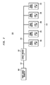
- a current chart 400 and voltage chart 410 for 28 V solenoids is illustrated.
- the current chart 400 and voltage chart 410 illustrate that the current draw 402 and voltage drop 404 for solenoids have an identifiable characteristic, a spike that occurs shortly after energizing, that can be used to develop a signature profile.
- a current draw 402 and voltage drop 404 are illustrated for a 28 V circuit, powering six 0.4 Amp solenoids as loads 112.
- the configuration for the current chart 400 and voltage chart 410 of Figures 4a and 4b is similar to the simplified system 100 in that no intelligent loads 212 are utilized.
- the initial current draw 402 is 0 Amps and the voltage drop 404 is 0 V.
- the bus 120 is a nominal 28 V circuit.
- one solenoid load 112 is activated, causing 0.4 Amps of current to be drawn. This also causes an approximate 0.75 V drop on the 28 V circuit.
- solenoid loads 112 are activated and deactivated.
- multiple solenoids are activated causing up to 1.8 Amps to be drawn, and causing a 3.5 V drop in the 28 V circuit.
- the circuit breaker 130, power source 140, and wiring 122, 120 must be capable of handling 1.8 Amps to prevent overheating or a circuit breaker 130 from tripping.
- the solenoid loads 112 or other loads 112 must be capable of operating using the lower 24.5 voltage provided on the 28 V circuit during periods of heavy utilization.
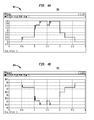
- a reduced current draw 502 and reduced voltage drop 504 are illustrated for a 28 V circuit, powering six 0.4 Amp solenoids configured as intelligent loads 212.
- the initial reduced current draw 502 is 0 Amps and the reduced voltage drop 504 is 0 V.
- the lower bus 220 is a nominal 28 V circuit.
- one solenoid configured as an intelligent load 212 is activated, causing 0.4 Amps of current to be drawn. This also causes an approximate 0.75 V drop on the 28 V circuit.
- no other solenoids configured as intelligent loads 212 activate until the first solenoid deactivates.
- the disclosed system and method provides substantial improvements when used for powering intelligent loads 500 that are used intermittently, for example electronic lock, cargo door motors, and single use maintenance displays.
- These and other low-usage loads can be installed with a minimum amount of power infrastructure necessary to support them, thereby allowing the electrical system designer to use lower power components, generators and wiring.
- Low power generators and wiring are generally smaller, have a lower cost, and have a lower weight, resulting in savings in space utilization, lower costs during manufacturing, and lower recurring fuel costs for the customer because of the decreased weight of the aircraft. Therefore the disclosed system and method advantageously permits the design and implementation of economical power systems and power infrastructures that are smaller and lighter than systems designed using conventional approaches.
- an exemplary flowchart of the method of operation 600 for an intelligent load 212 is presented.
- power is turned on 602 to the low power bus 220.
- the intelligent load 212 enters a state of waiting for activation 604, for example a user activating the intelligent load 212, such as a user opening a cargo door.
- the intelligent load 212 monitors the low power bus 220 for other intelligent loads 212 that might be actively drawing current from the low power bus 220. If another load is actively drawing current, then the intelligent load 212 delays 610 activating and then monitors 608 the low power bus 220 again. If no other load 212 is drawing current, the intelligent load 212 activates or operates 612 after which the intelligent load 212 returns to the operation of waiting for activation 604.
- An apparatus comprising: a switch for intermittently drawing power from a power bus; a load in electrical communication with said switch; a sensor for sensing an electrical state of said power bus; and a controller in communications with said switch and said sensing means; and wherein said controller controls said switch to intermittently draw power from said power bus for powering said load, based at least in part on said electrical state of said power bus.
- the apparatus may further comprise: a battery in electrical communication with said power bus through said switch; and wherein said battery is charged with a stored power using an intermittent power draw through said switch; and wherein said load is in electrical communication with said battery; and wherein said battery provides said stored power to said load when said switch is not drawing power from said power bus.
- said controller prevents said switch from drawing power from said power bus based upon a condition selected from the group consisting of a voltage drop on said power bus due to a second load drawing power from said power bus; a current increase on said power bus due to said second load drawing power from said power bus; and a received signal indicating said power bus is in use.
Landscapes
- Engineering & Computer Science (AREA)
- Power Engineering (AREA)
- Remote Monitoring And Control Of Power-Distribution Networks (AREA)
- Supply And Distribution Of Alternating Current (AREA)
Applications Claiming Priority (1)
| Application Number | Priority Date | Filing Date | Title |
|---|---|---|---|
| US12/896,691 US20120080940A1 (en) | 2010-10-01 | 2010-10-01 | Load Coordinating Power Draw for Limited Ampacity Circuits |
Publications (1)
| Publication Number | Publication Date |
|---|---|
| EP2437367A2 true EP2437367A2 (fr) | 2012-04-04 |
Family
ID=44719338
Family Applications (1)
| Application Number | Title | Priority Date | Filing Date |
|---|---|---|---|
| EP20110180161 Withdrawn EP2437367A2 (fr) | 2010-10-01 | 2011-09-06 | Grille électrique à coordination de chargement pour circuits de courant admissible limité |
Country Status (5)
| Country | Link |
|---|---|
| US (1) | US20120080940A1 (fr) |
| EP (1) | EP2437367A2 (fr) |
| JP (1) | JP2012080762A (fr) |
| CN (1) | CN102447257A (fr) |
| CA (1) | CA2747916A1 (fr) |
Families Citing this family (15)
| Publication number | Priority date | Publication date | Assignee | Title |
|---|---|---|---|---|
| US8679674B2 (en) * | 2005-03-25 | 2014-03-25 | Front Edge Technology, Inc. | Battery with protective packaging |
| US7846579B2 (en) | 2005-03-25 | 2010-12-07 | Victor Krasnov | Thin film battery with protective packaging |
| US8865340B2 (en) | 2011-10-20 | 2014-10-21 | Front Edge Technology Inc. | Thin film battery packaging formed by localized heating |
| US9887429B2 (en) | 2011-12-21 | 2018-02-06 | Front Edge Technology Inc. | Laminated lithium battery |
| US8864954B2 (en) | 2011-12-23 | 2014-10-21 | Front Edge Technology Inc. | Sputtering lithium-containing material with multiple targets |
| US9077000B2 (en) | 2012-03-29 | 2015-07-07 | Front Edge Technology, Inc. | Thin film battery and localized heat treatment |
| US9257695B2 (en) | 2012-03-29 | 2016-02-09 | Front Edge Technology, Inc. | Localized heat treatment of battery component films |
| US9159964B2 (en) | 2012-09-25 | 2015-10-13 | Front Edge Technology, Inc. | Solid state battery having mismatched battery cells |
| US8753724B2 (en) | 2012-09-26 | 2014-06-17 | Front Edge Technology Inc. | Plasma deposition on a partially formed battery through a mesh screen |
| US9356320B2 (en) | 2012-10-15 | 2016-05-31 | Front Edge Technology Inc. | Lithium battery having low leakage anode |
| KR20170003523A (ko) * | 2014-05-06 | 2017-01-09 | 마이크로칩 테크놀로지 인코포레이티드 | Usb 전력 포트 제어 |
| US10008739B2 (en) | 2015-02-23 | 2018-06-26 | Front Edge Technology, Inc. | Solid-state lithium battery with electrolyte |
| US10608432B2 (en) * | 2018-03-30 | 2020-03-31 | Midea Group Co., Ltd. | Appliance power management system |
| US11223201B1 (en) | 2020-07-10 | 2022-01-11 | Richard Bailey | Electrical power sharing system and method |
| JP7189191B2 (ja) | 2020-10-26 | 2022-12-13 | 矢崎総業株式会社 | 電源制御装置 |
Family Cites Families (35)
| Publication number | Priority date | Publication date | Assignee | Title |
|---|---|---|---|---|
| FR2088954A5 (fr) * | 1970-04-30 | 1972-01-07 | Radiotechnique Compelec | |
| US3925680A (en) * | 1975-04-04 | 1975-12-09 | William A Dixon | Method and system for regulating peak residential power demand |
| US4560909A (en) * | 1982-09-28 | 1985-12-24 | General Electric Company | Dual load remote power control for a ceiling fan |
| US4520274A (en) * | 1983-07-22 | 1985-05-28 | Stants Richard O | Method and apparatus for controlling the loads or a plurality of units on a shared source |
| US4777379A (en) * | 1984-11-02 | 1988-10-11 | Young Danny J | Power cycling apparatus |
| US4847722A (en) * | 1987-09-17 | 1989-07-11 | Bennett Robert P | Refrigerator and microwave oven and overdemand interrupt circuit |
| US4880954A (en) * | 1988-06-03 | 1989-11-14 | Bennett Robert P | Combined refrigerator and microwave oven with timed overload protection |
| JP2915037B2 (ja) * | 1990-01-08 | 1999-07-05 | 株式会社日立製作所 | 自動車用電気負荷の運転制御システム |
| US5504400A (en) * | 1994-09-23 | 1996-04-02 | Dalnodar; David C. | Two-channel AC light dimmer and lighting system |
| US5521359A (en) * | 1995-04-18 | 1996-05-28 | Bone; Charles A. | System for coordinating operation of microwave oven with a second appliance |
| US5883445A (en) * | 1996-10-22 | 1999-03-16 | Holman; Frank T. | Power sharing device |
| US5844326A (en) * | 1997-06-23 | 1998-12-01 | Cruising Equipment Company, Inc. | Managed electrical outlet for providing rank-ordered over-current protection |
| US6157008A (en) * | 1999-07-08 | 2000-12-05 | Maytag Corporation | Power distribution system for an appliance |
| US6826029B2 (en) * | 2001-08-30 | 2004-11-30 | The Boeing Company | Methods and apparatus for distributing electrical power |
| US20050280970A1 (en) * | 2004-06-16 | 2005-12-22 | Cyber Switching, Inc. | Current protection apparatus and method |
| DE10233876B4 (de) * | 2002-07-25 | 2005-03-03 | Austriamicrosystems Ag | Schaltungsanordnung zur Steuerung von zwei unabhängigen, mit einer gleichgerichteten Wechselspannung betreibbaren Lasten |
| US20040075343A1 (en) * | 2002-09-05 | 2004-04-22 | Paul Wareham | System and method for power load management |
| US6940272B2 (en) * | 2002-10-10 | 2005-09-06 | Green Socket Ltd. | Electric socket control device |
| US7373222B1 (en) * | 2003-09-29 | 2008-05-13 | Rockwell Automation Technologies, Inc. | Decentralized energy demand management |
| CA2543311A1 (fr) * | 2003-10-24 | 2005-05-06 | Square D Company | Systeme intelligent de commande de gestion d'energie |
| US7514815B2 (en) * | 2004-09-28 | 2009-04-07 | American Power Conversion Corporation | System and method for allocating power to loads |
| DE602005014883D1 (de) * | 2004-10-05 | 2009-07-23 | 2D2C Inc | Elektrisches stromverteilungssystem |
| US7547990B2 (en) * | 2005-07-12 | 2009-06-16 | Diran Varzhabedian | Backup power system for electrical appliances |
| WO2007082351A1 (fr) * | 2006-01-23 | 2007-07-26 | Datatainer Pty Ltd | Appareil de traitement de données |
| US7486056B2 (en) * | 2006-11-15 | 2009-02-03 | Elster Electricity, Llc | Input current or voltage limited power supply |
| TWI430534B (zh) * | 2007-05-08 | 2014-03-11 | American Power Conv Corp | 替代來源能量管理技術 |
| US7781908B2 (en) * | 2007-07-19 | 2010-08-24 | Igo, Inc. | Output power port management control |
| US20090164820A1 (en) * | 2007-12-24 | 2009-06-25 | Hewlett-Packard Development Company, L.P. | Methods and apparatus for managing power on a computer in the event of a power interruption |
| US7658625B2 (en) * | 2008-03-07 | 2010-02-09 | Microsoft Corporation | AC Power adapter with swiveling plug having folding prongs |
| TWI364518B (en) * | 2008-07-29 | 2012-05-21 | Ind Tech Res Inst | Power saving managing method and system using the same |
| US8504215B1 (en) * | 2008-11-04 | 2013-08-06 | Symantec Corporation | Systems and methods for using alternate power sources to manage the power draw on a power grid |
| JP2012514971A (ja) * | 2009-01-06 | 2012-06-28 | アクセス ビジネス グループ インターナショナル リミテッド ライアビリティ カンパニー | 装置電力コンプライアンスを有するワイヤレス充電システム |
| US8497658B2 (en) * | 2009-01-22 | 2013-07-30 | Qualcomm Incorporated | Adaptive power control for wireless charging of devices |
| US8315745B2 (en) * | 2009-04-24 | 2012-11-20 | Hunter Defense Technologies, Inc. | Mobile micro-grid power system controller and method |
| US8626319B2 (en) * | 2010-09-29 | 2014-01-07 | Rockwell Automation Technologies, Inc. | Modular energy load management |
-
2010
- 2010-10-01 US US12/896,691 patent/US20120080940A1/en not_active Abandoned
-
2011
- 2011-08-03 CA CA 2747916 patent/CA2747916A1/fr not_active Abandoned
- 2011-09-06 EP EP20110180161 patent/EP2437367A2/fr not_active Withdrawn
- 2011-09-23 CN CN2011102916127A patent/CN102447257A/zh active Pending
- 2011-09-26 JP JP2011209877A patent/JP2012080762A/ja not_active Withdrawn
Non-Patent Citations (1)
| Title |
|---|
| None |
Also Published As
| Publication number | Publication date |
|---|---|
| CA2747916A1 (fr) | 2012-04-01 |
| CN102447257A (zh) | 2012-05-09 |
| US20120080940A1 (en) | 2012-04-05 |
| JP2012080762A (ja) | 2012-04-19 |
Similar Documents
| Publication | Publication Date | Title |
|---|---|---|
| EP2437367A2 (fr) | Grille électrique à coordination de chargement pour circuits de courant admissible limité | |
| CN103633565B (zh) | 配电柜 | |
| EP2492133B1 (fr) | Dispositif de charge universel | |
| US9331523B2 (en) | Power control device and power control method | |
| EP2830188B1 (fr) | Chargeur sans fil équipé d'une alimentation électrique auxiliaire et dispositif de puissance auxiliaire | |
| KR101616233B1 (ko) | 충 방전 장치 | |
| US9193272B2 (en) | Jump-starting method and device for implementing the method | |
| US8917061B2 (en) | System and method for battery cell balancing | |
| JP2017123777A (ja) | 電荷移動管理方法および電荷移動装置 | |
| US20030155814A1 (en) | Device for power supply in a multi-voltage electric system of a motor vehicle | |
| US20110127935A1 (en) | Drive unit | |
| US20170077722A1 (en) | Battery pack, cell module and cell module assembly | |
| US20110304304A1 (en) | Charge controller and method of operating the same | |
| KR101383194B1 (ko) | 차량을 위한 온―보드 전기 시스템 및 또한 온―보드 전기 시스템을 위한 제어 장치 | |
| JP2019092257A (ja) | 制御装置、制御システム、蓄電装置及びプログラム | |
| CN105322641A (zh) | 包括用于调节输出的旁路电路的电池备用单元和系统 | |
| US10407005B2 (en) | Vehicle power supply control device | |
| CN107069691A (zh) | 用于故障穿越的系统和方法 | |
| EP2635799B1 (fr) | Dispositif d'activation et procédé d'activation pour un système à double batterie | |
| WO2013122073A1 (fr) | Dispositif de charge et d'alimentation électriques, dispositif de gestion de charge et d'alimentation électriques, système de gestion d'énergie et procédé de gestion de charge et d'alimentation électriques | |
| US10511177B2 (en) | Modular charging system and method of delivering electric power through the same | |
| CN105846519A (zh) | 用于从ac供电系统对高压电池电力充电的方法和设备 | |
| JP2022075347A (ja) | 充電制御装置、充電システム、充電制御方法及びプログラム | |
| CN101908773A (zh) | 电池组充/放电系统及方法 | |
| CN113839456B (zh) | 一种电能传输系统和方法 |
Legal Events
| Date | Code | Title | Description |
|---|---|---|---|
| PUAI | Public reference made under article 153(3) epc to a published international application that has entered the european phase |
Free format text: ORIGINAL CODE: 0009012 |
|
| 17P | Request for examination filed |
Effective date: 20110906 |
|
| AK | Designated contracting states |
Kind code of ref document: A2 Designated state(s): AL AT BE BG CH CY CZ DE DK EE ES FI FR GB GR HR HU IE IS IT LI LT LU LV MC MK MT NL NO PL PT RO RS SE SI SK SM TR |
|
| AX | Request for extension of the european patent |
Extension state: BA ME |
|
| STAA | Information on the status of an ep patent application or granted ep patent |
Free format text: STATUS: THE APPLICATION HAS BEEN WITHDRAWN |
|
| 18W | Application withdrawn |
Effective date: 20141209 |