EP2437105B1 - Display apparatus - Google Patents
Display apparatus Download PDFInfo
- Publication number
- EP2437105B1 EP2437105B1 EP11177847.8A EP11177847A EP2437105B1 EP 2437105 B1 EP2437105 B1 EP 2437105B1 EP 11177847 A EP11177847 A EP 11177847A EP 2437105 B1 EP2437105 B1 EP 2437105B1
- Authority
- EP
- European Patent Office
- Prior art keywords
- light
- substrate
- display apparatus
- body part
- light source
- Prior art date
- Legal status (The legal status is an assumption and is not a legal conclusion. Google has not performed a legal analysis and makes no representation as to the accuracy of the status listed.)
- Not-in-force
Links
Images


Classifications
-
- G—PHYSICS
- G02—OPTICS
- G02F—OPTICAL DEVICES OR ARRANGEMENTS FOR THE CONTROL OF LIGHT BY MODIFICATION OF THE OPTICAL PROPERTIES OF THE MEDIA OF THE ELEMENTS INVOLVED THEREIN; NON-LINEAR OPTICS; FREQUENCY-CHANGING OF LIGHT; OPTICAL LOGIC ELEMENTS; OPTICAL ANALOGUE/DIGITAL CONVERTERS
- G02F1/00—Devices or arrangements for the control of the intensity, colour, phase, polarisation or direction of light arriving from an independent light source, e.g. switching, gating or modulating; Non-linear optics
- G02F1/01—Devices or arrangements for the control of the intensity, colour, phase, polarisation or direction of light arriving from an independent light source, e.g. switching, gating or modulating; Non-linear optics for the control of the intensity, phase, polarisation or colour
- G02F1/13—Devices or arrangements for the control of the intensity, colour, phase, polarisation or direction of light arriving from an independent light source, e.g. switching, gating or modulating; Non-linear optics for the control of the intensity, phase, polarisation or colour based on liquid crystals, e.g. single liquid crystal display cells
- G02F1/133—Constructional arrangements; Operation of liquid crystal cells; Circuit arrangements
- G02F1/1333—Constructional arrangements; Manufacturing methods
- G02F1/133308—Support structures for LCD panels, e.g. frames or bezels
-
- G—PHYSICS
- G02—OPTICS
- G02F—OPTICAL DEVICES OR ARRANGEMENTS FOR THE CONTROL OF LIGHT BY MODIFICATION OF THE OPTICAL PROPERTIES OF THE MEDIA OF THE ELEMENTS INVOLVED THEREIN; NON-LINEAR OPTICS; FREQUENCY-CHANGING OF LIGHT; OPTICAL LOGIC ELEMENTS; OPTICAL ANALOGUE/DIGITAL CONVERTERS
- G02F1/00—Devices or arrangements for the control of the intensity, colour, phase, polarisation or direction of light arriving from an independent light source, e.g. switching, gating or modulating; Non-linear optics
- G02F1/01—Devices or arrangements for the control of the intensity, colour, phase, polarisation or direction of light arriving from an independent light source, e.g. switching, gating or modulating; Non-linear optics for the control of the intensity, phase, polarisation or colour
- G02F1/13—Devices or arrangements for the control of the intensity, colour, phase, polarisation or direction of light arriving from an independent light source, e.g. switching, gating or modulating; Non-linear optics for the control of the intensity, phase, polarisation or colour based on liquid crystals, e.g. single liquid crystal display cells
- G02F1/133—Constructional arrangements; Operation of liquid crystal cells; Circuit arrangements
- G02F1/1333—Constructional arrangements; Manufacturing methods
- G02F1/1335—Structural association of cells with optical devices, e.g. polarisers or reflectors
- G02F1/1336—Illuminating devices
- G02F1/133615—Edge-illuminating devices, i.e. illuminating from the side
-
- G—PHYSICS
- G02—OPTICS
- G02F—OPTICAL DEVICES OR ARRANGEMENTS FOR THE CONTROL OF LIGHT BY MODIFICATION OF THE OPTICAL PROPERTIES OF THE MEDIA OF THE ELEMENTS INVOLVED THEREIN; NON-LINEAR OPTICS; FREQUENCY-CHANGING OF LIGHT; OPTICAL LOGIC ELEMENTS; OPTICAL ANALOGUE/DIGITAL CONVERTERS
- G02F1/00—Devices or arrangements for the control of the intensity, colour, phase, polarisation or direction of light arriving from an independent light source, e.g. switching, gating or modulating; Non-linear optics
- G02F1/01—Devices or arrangements for the control of the intensity, colour, phase, polarisation or direction of light arriving from an independent light source, e.g. switching, gating or modulating; Non-linear optics for the control of the intensity, phase, polarisation or colour
- G02F1/13—Devices or arrangements for the control of the intensity, colour, phase, polarisation or direction of light arriving from an independent light source, e.g. switching, gating or modulating; Non-linear optics for the control of the intensity, phase, polarisation or colour based on liquid crystals, e.g. single liquid crystal display cells
- G02F1/133—Constructional arrangements; Operation of liquid crystal cells; Circuit arrangements
- G02F1/1333—Constructional arrangements; Manufacturing methods
- G02F1/133308—Support structures for LCD panels, e.g. frames or bezels
- G02F1/133314—Back frames
-
- G—PHYSICS
- G02—OPTICS
- G02F—OPTICAL DEVICES OR ARRANGEMENTS FOR THE CONTROL OF LIGHT BY MODIFICATION OF THE OPTICAL PROPERTIES OF THE MEDIA OF THE ELEMENTS INVOLVED THEREIN; NON-LINEAR OPTICS; FREQUENCY-CHANGING OF LIGHT; OPTICAL LOGIC ELEMENTS; OPTICAL ANALOGUE/DIGITAL CONVERTERS
- G02F1/00—Devices or arrangements for the control of the intensity, colour, phase, polarisation or direction of light arriving from an independent light source, e.g. switching, gating or modulating; Non-linear optics
- G02F1/01—Devices or arrangements for the control of the intensity, colour, phase, polarisation or direction of light arriving from an independent light source, e.g. switching, gating or modulating; Non-linear optics for the control of the intensity, phase, polarisation or colour
- G02F1/13—Devices or arrangements for the control of the intensity, colour, phase, polarisation or direction of light arriving from an independent light source, e.g. switching, gating or modulating; Non-linear optics for the control of the intensity, phase, polarisation or colour based on liquid crystals, e.g. single liquid crystal display cells
- G02F1/133—Constructional arrangements; Operation of liquid crystal cells; Circuit arrangements
- G02F1/1333—Constructional arrangements; Manufacturing methods
- G02F1/133308—Support structures for LCD panels, e.g. frames or bezels
- G02F1/13332—Front frames
-
- G—PHYSICS
- G02—OPTICS
- G02F—OPTICAL DEVICES OR ARRANGEMENTS FOR THE CONTROL OF LIGHT BY MODIFICATION OF THE OPTICAL PROPERTIES OF THE MEDIA OF THE ELEMENTS INVOLVED THEREIN; NON-LINEAR OPTICS; FREQUENCY-CHANGING OF LIGHT; OPTICAL LOGIC ELEMENTS; OPTICAL ANALOGUE/DIGITAL CONVERTERS
- G02F1/00—Devices or arrangements for the control of the intensity, colour, phase, polarisation or direction of light arriving from an independent light source, e.g. switching, gating or modulating; Non-linear optics
- G02F1/01—Devices or arrangements for the control of the intensity, colour, phase, polarisation or direction of light arriving from an independent light source, e.g. switching, gating or modulating; Non-linear optics for the control of the intensity, phase, polarisation or colour
- G02F1/13—Devices or arrangements for the control of the intensity, colour, phase, polarisation or direction of light arriving from an independent light source, e.g. switching, gating or modulating; Non-linear optics for the control of the intensity, phase, polarisation or colour based on liquid crystals, e.g. single liquid crystal display cells
- G02F1/133—Constructional arrangements; Operation of liquid crystal cells; Circuit arrangements
- G02F1/1333—Constructional arrangements; Manufacturing methods
- G02F1/133308—Support structures for LCD panels, e.g. frames or bezels
- G02F1/133322—Mechanical guidance or alignment of LCD panel support components
-
- G—PHYSICS
- G02—OPTICS
- G02F—OPTICAL DEVICES OR ARRANGEMENTS FOR THE CONTROL OF LIGHT BY MODIFICATION OF THE OPTICAL PROPERTIES OF THE MEDIA OF THE ELEMENTS INVOLVED THEREIN; NON-LINEAR OPTICS; FREQUENCY-CHANGING OF LIGHT; OPTICAL LOGIC ELEMENTS; OPTICAL ANALOGUE/DIGITAL CONVERTERS
- G02F1/00—Devices or arrangements for the control of the intensity, colour, phase, polarisation or direction of light arriving from an independent light source, e.g. switching, gating or modulating; Non-linear optics
- G02F1/01—Devices or arrangements for the control of the intensity, colour, phase, polarisation or direction of light arriving from an independent light source, e.g. switching, gating or modulating; Non-linear optics for the control of the intensity, phase, polarisation or colour
- G02F1/13—Devices or arrangements for the control of the intensity, colour, phase, polarisation or direction of light arriving from an independent light source, e.g. switching, gating or modulating; Non-linear optics for the control of the intensity, phase, polarisation or colour based on liquid crystals, e.g. single liquid crystal display cells
- G02F1/133—Constructional arrangements; Operation of liquid crystal cells; Circuit arrangements
- G02F1/1333—Constructional arrangements; Manufacturing methods
- G02F1/1335—Structural association of cells with optical devices, e.g. polarisers or reflectors
- G02F1/133524—Light-guides, e.g. fibre-optic bundles, louvered or jalousie light-guides
-
- G—PHYSICS
- G02—OPTICS
- G02F—OPTICAL DEVICES OR ARRANGEMENTS FOR THE CONTROL OF LIGHT BY MODIFICATION OF THE OPTICAL PROPERTIES OF THE MEDIA OF THE ELEMENTS INVOLVED THEREIN; NON-LINEAR OPTICS; FREQUENCY-CHANGING OF LIGHT; OPTICAL LOGIC ELEMENTS; OPTICAL ANALOGUE/DIGITAL CONVERTERS
- G02F1/00—Devices or arrangements for the control of the intensity, colour, phase, polarisation or direction of light arriving from an independent light source, e.g. switching, gating or modulating; Non-linear optics
- G02F1/01—Devices or arrangements for the control of the intensity, colour, phase, polarisation or direction of light arriving from an independent light source, e.g. switching, gating or modulating; Non-linear optics for the control of the intensity, phase, polarisation or colour
- G02F1/13—Devices or arrangements for the control of the intensity, colour, phase, polarisation or direction of light arriving from an independent light source, e.g. switching, gating or modulating; Non-linear optics for the control of the intensity, phase, polarisation or colour based on liquid crystals, e.g. single liquid crystal display cells
- G02F1/133—Constructional arrangements; Operation of liquid crystal cells; Circuit arrangements
- G02F1/1333—Constructional arrangements; Manufacturing methods
- G02F1/1335—Structural association of cells with optical devices, e.g. polarisers or reflectors
- G02F1/1336—Illuminating devices
- G02F1/133602—Direct backlight
- G02F1/133608—Direct backlight including particular frames or supporting means
-
- G—PHYSICS
- G02—OPTICS
- G02F—OPTICAL DEVICES OR ARRANGEMENTS FOR THE CONTROL OF LIGHT BY MODIFICATION OF THE OPTICAL PROPERTIES OF THE MEDIA OF THE ELEMENTS INVOLVED THEREIN; NON-LINEAR OPTICS; FREQUENCY-CHANGING OF LIGHT; OPTICAL LOGIC ELEMENTS; OPTICAL ANALOGUE/DIGITAL CONVERTERS
- G02F1/00—Devices or arrangements for the control of the intensity, colour, phase, polarisation or direction of light arriving from an independent light source, e.g. switching, gating or modulating; Non-linear optics
- G02F1/01—Devices or arrangements for the control of the intensity, colour, phase, polarisation or direction of light arriving from an independent light source, e.g. switching, gating or modulating; Non-linear optics for the control of the intensity, phase, polarisation or colour
- G02F1/13—Devices or arrangements for the control of the intensity, colour, phase, polarisation or direction of light arriving from an independent light source, e.g. switching, gating or modulating; Non-linear optics for the control of the intensity, phase, polarisation or colour based on liquid crystals, e.g. single liquid crystal display cells
- G02F1/133—Constructional arrangements; Operation of liquid crystal cells; Circuit arrangements
- G02F1/1333—Constructional arrangements; Manufacturing methods
- G02F1/1335—Structural association of cells with optical devices, e.g. polarisers or reflectors
- G02F1/1336—Illuminating devices
- G02F1/133628—Illuminating devices with cooling means
-
- G—PHYSICS
- G02—OPTICS
- G02F—OPTICAL DEVICES OR ARRANGEMENTS FOR THE CONTROL OF LIGHT BY MODIFICATION OF THE OPTICAL PROPERTIES OF THE MEDIA OF THE ELEMENTS INVOLVED THEREIN; NON-LINEAR OPTICS; FREQUENCY-CHANGING OF LIGHT; OPTICAL LOGIC ELEMENTS; OPTICAL ANALOGUE/DIGITAL CONVERTERS
- G02F2201/00—Constructional arrangements not provided for in groups G02F1/00 - G02F7/00
- G02F2201/46—Fixing elements
- G02F2201/465—Snap -fit
Definitions
- the subject matter described herein relates to a backlight assembly and a display apparatus having the backlight assembly.
- a display apparatus such as a liquid crystal display or an electrophoretic display, includes a liquid crystal display panel or an electrophoretic display panel to display an image.
- the display apparatus since the liquid crystal display panel or the electrophoretic display panel is not self-emissive, the display apparatus requires a backlight assembly to supply the liquid crystal display panel or the electrophoretic display panel with light.
- the backlight assembly includes a plurality of light sources.
- the backlight assembly includes a light emitting diode as the light source, which has properties such as low power consumption, lightweight, and slimness when compared to a cold cathode fluorescent lamp.
- WO 2009/118942 discloses a display apparatus as recited in the pre-characterising portion of claim 1.
- the invention provides a display apparatus as in claim 1.
- Exemplary embodiments of the subject matter described herein provide a backlight assembly capable of improving heat dissipating property and reducing display defects.
- Exemplary embodiments of the subject matter described herein provide a display apparatus having the backlight assembly.
- a backlight assembly includes a light source unit, a support, further referred to as supporter, a light guide plate, and alternatively a display panel.
- the light source unit includes a substrate and a plurality of light sources arranged on a front surface of the substrate to emit a light
- the supporter supports the light source unit
- the light guide plate includes a light incident surface to which the light is incident and a light exiting surface from which the light exits.
- the light incident surface of the light guide plate faces the front surface of the substrate
- the supporter includes a body part making contact with a rear surface of the light source unit, a bottom part extending from a lower portion of the body part in a direction substantially parallel to the light exiting surface, a protruding part disposed on the bottom part and comprising a surface making contact with the substrate, and a cover part coupled to the body part to cover an upper portion of the substrate and press the substrate in a direction in which the bottom part is disposed.
- the surface of the protruding part is inclined to the front surface of the substrate.
- the protruding part is extended in a longitudinal direction of the substrate.
- the protruding part is provided in a plural number and the protruding parts are arranged in a longitudinal direction of the substrate.
- the cover part includes a first portion making contact with an upper portion of the body part, a second portion extending from the first portion and comprising a surface making contact with the substrate, and a coupling member coupling the first portion to the body part.
- the coupling member may be a screw, hook, or elastic clip.
- the display apparatus of claim may further include a mold frame provided at at least one side of the supporter to support an end of the display panel, and the cover part may be integrally formed with the mold frame.
- the display apparatus may further include a bottom chassis to accommodate the light source unit, the supporter, and the light guide plate therein, and the body part, the bottom part, and the protruding part may be integrally formed with the bottom chassis.
- the display apparatus does not need heat radiation tape, heat radiation grease, an additional screw hole, and thus the assembling process for the display apparatus may become simplified and the manufacturing cost for the display apparatus may be reduced.
- FIG. 1 is an exploded perspective view showing a display apparatus according to a first exemplary embodiment
- FIG. 2 is a cross-sectional view taken along a line I-I' of FIG. 1 ;
- FIG. 3 is a partial perspective view showing a backlight assembly in the display apparatus of FIG. 1 ;
- FIG 4 is a cross-sectional view taken along a line II-II' of FIG 3 ;
- FIG 5 is a partial perspective view showing a backlight assembly of a display apparatus according to a second exemplary embodiment
- FIG 6 is a cross-sectional view taken along a line III-III' of FIG 5 ;
- FIG 7 is a partial perspective view showing a backlight assembly of a display apparatus according to a third exemplary embodiment
- FIG. 8 is a cross-sectional view taken along a IV-IV of FIG 7 ;
- FIG 9 is a cross-sectional view showing a backlight assembly of a display apparatus according to a fourth exemplary embodiment.
- FIG 10 is a cross-sectional view showing a backlight assembly of a display apparatus according to a fifth exemplary embodiment
- FIG 11 is a cross-sectional view showing a display apparatus according to a sixth exemplary embodiment.
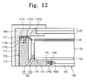
- FIG 12 is a cross-sectional view showing a display apparatus according to a seventh exemplary embodiment.
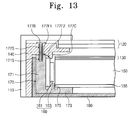
- FIG 13 is a cross-sectional view showing a display apparatus according to an eighth exemplary embodiment.
- first, second, etc. may be used herein to describe various elements, components, regions, layers and/or sections, these elements, components, regions, layers and/or sections should not be limited by these terms. These terms are only used to distinguish one element, component, region, layer or section from another region, layer or section. Thus, a first element, component, region, layer or section discussed below could be termed a second element, component, region, layer or section without departing from the teachings of the present invention.
- spatially relative terms such as “beneath”, “below”, “lower”, “above”, “upper” and the like, may be used herein for ease of description to describe one element or feature's relationship to another element(s) or feature(s) as illustrated in the figures. It will be understood that the spatially relative terms are intended to encompass different orientations of the device in use or operation in addition to the orientation depicted in the figures. For example, if the device in the figures is turned over, elements described as “below” or “beneath” other elements or features would then be oriented “above” the other elements or features. Thus, the exemplary term “below” can encompass both an orientation of above and below. The device may be otherwise oriented (rotated 90 degrees or at other orientations) and the spatially relative descriptors used herein interpreted accordingly.
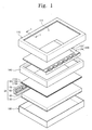
- FIG 1 is an exploded perspective view showing a display apparatus according to a first exemplary embodiment and FIG 2 is a cross-sectional view taken along a line I-I' of FIG 1 .
- a display apparatus includes a display panel 120, a mold frame 140, a backlight assembly BA, a bottom chassis 180, and a top chassis 110.
- the display panel 120 displays an image.
- the display panel 120 may be a liquid crystal display panel or an electrophoretic display panel.
- the liquid crystal display panel will be described as an example for the display panel.
- the display panel 120 has a rectangular plate-like shape including a long side and a short side.
- the display panel 120 includes a first substrate 124, a second substrate 122 facing the first substrate 124, and a liquid crystal layer (not shown) disposed between the first substrate 124 and the second substrate 122.
- the first substrate 124 may include pixel electrodes (not shown) and thin film transistors (not shown) electrically connected to the pixel electrodes in one-to-one correspondence. Each thin film transistor switches a driving signal applied to a corresponding pixel electrode of the pixel electrodes.
- the second substrate 122 may include a common electrode (not shown) that forms an electric field together with the pixel electrodes to control arrangement of liquid crystal molecules of the liquid crystal layer.
- the display panel 120 may drive the liquid crystal layer and display an image.
- the mold frame 140 is provided along an end of the display panel 120 and disposed below the display panel 120 to support the display panel 120.
- the mold frame 140 has a substantially rectangular ring shape.
- the mold frame 140 may be provided in singular or plural numbers.
- the backlight assembly BA is provided under the display panel 120 to supply a light to the display panel 120.
- the backlight assembly BA includes a light source part, a light guide plate 150, an optical sheet 130, and a reflective sheet 155. Details of the backlight assembly BA will be described later.
- the top chassis 110 is disposed on the display panel 120.
- the top chassis 110 covers a front end of the display panel 120 and a side surface of the mold frame 140 or a side surface of the bottom chassis 180.
- the top chassis 111 is provided with a window 111 formed therethrough to expose a display area of the display panel 120.
- the bottom chassis 180 is disposed under the backlight assembly BA to accommodate the backlight assembly BA.
- the bottom chassis 180 may include a bottom portion 181 substantially parallel to a rear surface of the reflective sheet 155 and a sidewall portion 183 upwardly extended from the bottom portion 181.
- the backlight assembly BA is accommodated in a space defined by the bottom portion 181 and the sidewall portion 183.
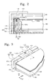
- FIG 3 is a partial perspective view showing a backlight assembly in the display apparatus of FIG 1 and
- FIG 4 is a cross-sectional view taken along a line II-II' of FIG 3 .
- the backlight assembly BA includes the light source part that emits the light, a light guide plate 150 that guides the light to the display panel 120, the optical sheet 130 that improves the light efficiency of the light, and the reflective sheet 155 that changes a path in which the light travels.
- a direction in which the light emitting from the light source part travels is referred to as a first direction D1
- a direction substantially parallel to an upper surface of the bottom chassis 180 and vertical to the first direction D1 is referred to as a second direction D2
- a direction substantially vertical to the first direction D1 and the second direction D2 is referred to as a third direction D3.
- the third direction D3 is a direction from the reflective sheet 155 to the display panel 120.
- the light source part provides the light traveling in the first direction D1 to the light guide plate 150.
- the light source part includes a light source unit 160 supplying the light to the light guide plate 150 and a supporter 170 supporting the light source unit 160.
- the light guide plate 150 has a rectangular plate-like shape and is disposed under the display panel 120. Most wide two surfaces of surfaces forming the light guide plate 150 are positioned parallel to the display panel 120.
- the light guide plate 150 guides the light to the display panel 120.
- the light guide plate 150 includes a light incident surface 151A to which the light is incident and a light exiting surface 151B from which the light exits.
- the light incident surface 151 A faces a front face of the light source unit 160.
- the light emitted from the light source unit 160 is incident inside the light guide plate 150 through the light incident surface 151A.
- the light exiting surface 151B faces the display panel 120.
- the light that is incident inside the light guide plate 150 travels to the display panel 120 through the light emitting surface 151B.
- the light incident surface 151A and the light exiting surface 151B are connected to each other, but it should not be limited thereto or thereby.
- the positions of the light incident surface 151A and the light exiting surface 151B depend on the position of the light source unit 160.
- the light incident surface 151A and the light exiting surface 151B are positioned to be parallel to each other.
- one light incident surface 151A has been shown, but the number of the light incident surfaces should not be limited thereto.
- the light source unit 160 may be provided in plural numbers and the light source units may be disposed along the side surface of the light guide plate 150. In this case, plural light incident surfaces exist in the light guide plate.
- the light guide plate 150 may be formed of a transparent polymer resin such as polycarbonate, polymethylmethacrylate, etc.
- the optical sheet 130 is disposed between the light guide plate 150 and the display panel 120 to control the light emitted from the light source unit 160.
- the optical sheet 130 includes a diffusion sheet 136, a prism sheet 134, and a protective sheet 132, which are sequentially stacked on the light guide plate 150.
- the diffusion sheet 136 diffuses the light and the prism sheet 134 condenses the diffused light such that the light travels to a direction vertical to the lower surface of the display panel 120.
- the protective sheet 132 is disposed on the prism sheet 134 to protect the prism sheet 134 from external impacts.
- one optical sheet 136, one prism sheet 134, and one protective sheet 132 have been shown, but the optical sheet 136, the prism sheet 134, or the protective sheet 132 may be provided in plural numbers or omitted.
- the reflective sheet 155 is disposed under the light guide plate 150 to reflect the light, which does not travel to the display panel 120, to the display panel 120.
- the reflective sheet 155 includes a material that reflects the light.
- the reflective sheet 155 is disposed on the bottom chassis 180 to reflect the light. As a result, the reflective sheet 155 may increase an amount of the light supplied to the display panel 120.
- the light source unit 160 includes a substrate 161 and a plurality of light sources 163.
- the substrate 161 has a rectangular-plate shape.
- the substrate 161 has a front surface facing the light incident surface 151A of the light guide plate 150 and being spaced apart from the light incident surface 151A.
- the light sources 163 are mounted on the front surface of the substrate 161 that is spaced apart from the light guide plate 150.
- the light sources 163 may be various light sources, such as a point light source, a line light source, a surface light source, etc., but it should not be limited thereto.
- a light emitting diode (LED) used as a point light source will be described as a representative example.
- the LED may be provided in plural numbers and arranged in a line along the second direction D2 on the substrate 161.
- the supporter 170 is disposed adjacent to the light source unit 160 to support and hold the light source unit 160.
- the supporter 170 includes a body part 171, a bottom part 173, a protruding part 175, and a cover part 177.
- the body part 171 includes a front surface substantially parallel to the light incident surface 151A and a rear surface opposite to the front surface.
- the body part 171 is extended in the second direction D2 corresponding to the substrate 161 and the front surface of the body part 171 makes contact with the rear surface of the substrate 161.
- the rear surface of the body part 171 makes contact with the bottom chassis 180.
- the body part 171 is provided with a first coupling recess 171 S to which the cover part 177 is coupled.
- the first coupling recess 171 S is provided at upper portion of the body part 171, but it should not be limited thereto. That is, the first coupling recess 171 S may be provided at a side portion of the body part 171.
- the bottom part 173 is extended in the first direction D1 from an end of the body part 171 such that a portion of the bottom part 173 is disposed under the light guide plate 150.
- the end portion of the bottom part 173 in the first direction D1 is partially overlapped with an end of the light guide plate 150 when viewed in a plan view.
- An upper surface of the bottom part 173 is provided to be substantially parallel to the light exiting surface 151B to support the light guide plate 150, the optical sheet 130, and the reflective sheet 155.
- the protruding part 175 is provided on the bottom part 173 and disposed between the body part 171 and the reflective sheet 155.
- the protruding part 175 has a wedge shape and is upwardly protruded toward the third direction D3.
- the protruding part 175 is extended in the second direction D2.
- the wedge shape of the protruding part 175 has a substantial triangular shape of which a width of the triangular shape is gradually decreased from the bottom part 173 to the third direction D3 in a cross-sectional view taken along the first direction D1.
- the triangular shape may be a right-angled triangular shape including a hypotenuse side facing the substrate 161 of the light source unit 160.
- the surface of the protruding part 175, which is corresponding to the hypotenuse side, is inclined to the light exiting surface 151B.
- the protruding part 175 is extended in the second direction D2 and is provided in a singular form, however it should not be limited thereto. That is, the protruding portion 175 may have a short length such that the protruding portion 175 partially makes contact with the lower portion of the substrate 161. In this case, the protruding part 175 may be provided in a plural number in the second direction D2.
- the cover part 177 includes a fixing portion 177C and a first coupling member 177B.
- the cover part 177 presses the light source unit 160 to the downward direction to prevent the light source unit 160 from being separated in the upward direction.
- the fixing portion 177C has a plate-like shape.
- the fixing portion 177C includes a first portion 177C1 and a second portion 177C2.
- the first portion 177C1 is substantially parallel to the light exiting surface 151B and covers the upper surface of the body part 171, and the second portion 177C2 is disposed on the upper end of the substrate 161 and bent to the substrate 161, thereby making contact with the upper end of the substrate 161.
- the second portion 177C2 is inclined to the light exiting surface 151B and the second portion 177C2 and the substrate 161 form an acute angle.
- the fixing portion 177C is provided with a second through hole 177S having the same diameter as the first coupling recess 171S.
- the fixing portion 177C may be extended in the second direction D2 to cover the whole upper surface of the substrate 161, but is should not be limited thereto. That is, as shown in FIG 3 , the fixing portion 177C may be provided to cover a portion of the upper surface of the substrate 161. In addition, the fixing portion 177C may be provided in a plural number.
- the first coupling member 177B may be a screw coupled with the first coupling recess 171 S and the second through hole 177S.
- the first coupling member 177B passes through the second through hole 177S and is coupled with the first coupling recess 171 S.
- the first coupling member 177B allows the cover part 177 to press the substrate 161 to the downward direction in addition to the function of coupling the cover part 177 to the body part 171.
- the supporter 170 and the fixing portion 177C may be formed of a metal material having a good elasticity, such as stainless, phosphor bronze, etc., but it should not be limited thereto.
- the fixing portion 177C may be formed of a plastic material having superior elasticity.
- the light source unit 160 is firmly fixed to the supporter 170.
- the light source unit 160 is disposed between the body part 171 and the protruding part 175.
- the cover part 177 is disposed on the light source unit 160 and the body part 171 and is coupled with the body part 171 by using the first coupling member 177B. Accordingly, a first force F1 is applied to the substrate 161 from the upward direction to the downward direction (e.g., a reverse direction to the third direction D3).
- the substrate 161 moves downwardly by the first force F1 and the substrate 161 makes contact with the hypotenuse side of the protruding part 175, the first force F1 is converted to a second force F2 operated to a reverse direction to the first direction D1.
- the substrate 161 may be firmly fixed to the body part 171 of the supporter 170.
- the angle ⁇ is in a range of about 15 degrees to about 75 degrees.
- the angle ⁇ is larger than 75 degrees, the space in which the substrate 161 is fixed to the bottom part 173 is insufficient, and when the angle ⁇ is smaller than 15 degrees, the substrate 161 may not be firmly fixed to the body part 171 because the second force F2 is insufficient.
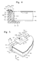
- FIG 5 is a partial perspective view showing a backlight assembly of a display apparatus according to a second exemplary embodiment
- FIG 6 is a cross-sectional view taken along a line III-III' of FIG 5 .
- the cover part 177 presses the light source unit 160 and the light guide plate 150 to the downward direction to fix the light source unit 160 and the light guide plate 150 to the supporter 170.
- the cover part 177 includes a fixing portion 177C, an extending portion 177E, and a first coupling member 177B.
- the fixing portion 177C has a plate-like shape.
- the fixing portion 177C includes a first portion 177C1 and a second portion 177C2.
- the first portion 177C1 is substantially parallel to the light exiting surface 151B and covers the upper surface of the body part 171, and the second portion 177C2 is disposed on the upper end of the substrate 161 and bent to the substrate 161, thereby making contact with the upper end of the substrate 161.
- the second portion 177C2 is inclined to the light exiting surface 151B and the second portion 177C2 and the substrate 161 form an acute angle.
- the second portion 177C2 of the fixing portion 177C covers the upper end of the substrate 161 and presses the light source unit 160 to the downward direction.
- the extending portion 177E has a plate-like shape.
- the extending portion 177E includes a first portion 177E1 and a second portion 177E2.
- the first portion 177E1 is substantially parallel to the light exiting surface 151B and covers the upper surface of the body part 171, and the second portion 177E2 is disposed on the upper end of the optical sheet 130 and the light guide plate 150 and bent to the downward direction, thereby making contact with the upper end of the optical sheet 130.
- the second portion 177E2 is overlapped with an end of the light guide plate 150 in a plan view.
- the second portion 177E2 of the extending portion 177E presses the upper end of the optical sheet 130 disposed on the light guide plate 150 to the downward direction.
- the first portion 177C1 of the fixing portion 177C is connected with the first portion 177E1 of the extending portion 177E in the same horizontal plane as shown in FIG 5 .
- the fixing portion 177C and the extending portion 177E may be integrally formed with each other, and in this case the fixing portion 177C and the extending portion 177E integrally formed with the fixing portion 177C are extended in the second direction D2.
- the fixing portion 177C and the extending portion 177E are provided in a singular form, but it should not be limited thereto. That is, the fixing portion 177C and the extending portion 177E may be provided in a plural number such that the fixing portion 177C and the extending portion 177E partially cover the upper of the substrate 161.
- At least one portion of the first portion 177C1 of the fixing portion 177C or the first portion 177E1 of the extending portion 177E is provided with a second through hole 177S having the same diameter as the first coupling recess 171S of the body part 171.
- the first coupling member 177B is used to couple the fixing portion 177C and the extending portion 177E to the body part 171.
- the first coupling member 177B may be a screw coupled to the first coupling recess 171 S of the body part 171 and the second through hole 177S formed through the first portion 177C1 of the fixing portion 177C or the first portion 177E1 of the extending portion 177E.
- the first coupling member 177B is coupled to the first coupling recess 171 S after passing through the second through hole 177S.
- the light source unit 160 and supporter 170 are fixed to each other and the optical sheet 130 and the light guide plate 150 are firmly fixed to the supporter 171.
- the optical sheet 130 and the light guide plate 150 may be prevented from sagging.
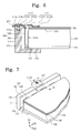
- FIG 7 is a partial perspective view showing a backlight assembly of a display apparatus according to a third exemplary embodiment
- FIG. 8 is a cross-sectional view taken along a IV-IV' of FIG 7 .
- the cover part 177 may be formed of a material having elasticity, such as rubber-based material, silicon-based material, or the like, to fix the body part 171 and the substrate 161.
- the cover part 177 includes a first portion 177P1 disposed on the body part 171 and the substrate 161, a second portion 177P2 extended in the downward direction from both ends of the first portion 177P1 in the first direction D1, and the first coupling member 177B.
- the second portion 177P2 includes a first protrusion protruded from a first end of the first portion 177P1 and a second protrusion protruded from a second end of the first portion 177P1.
- the first portion 177P1 and the second portion 177P2 are integrally formed with each other.
- a distance between a lower end of the first protrusion and a lower end of the second protrusion is smaller than a sum of a thickness of the supporter 170 and a thickness of the substrate 161 before the cover part 177 is coupled with the supporter 170 and the substrate 161.
- the lower surface of the first portion 177P1 makes contact with the upper surface of the body part 171 and the upper end of the substrate 161 and the second portion 177P2 makes contact with the rear surface of the body part 171 and the front surface of the substrate 161. Since the distance between the first and second protrusions is smaller than the sum of the thickness of the body part 171 and the thickness of the substrate 161, the first and second protrusions may make contact with the body part 171 and the substrate 161, respectively, by their elasticity, thereby firmly fixing the substrate 161 to the supporter 170.
- the first portion 177P1 is provided with the second through hole 177S having the same diameter as the first coupling recess 171S to correspond to the first coupling recess 171S.
- the first coupling member 177B may be a screw coupled with the first coupling recess 171 S and the second through hole 177S to couple the first portion 177P1 of the cover part 177 to the body part 171.
- the first coupling member 177B is coupled with the first coupling recess 171 S after passing through the second through hole 177S.
- the first coupling member 177B may press the substrate 161 downward direction by using the first and second portions 177P1 and 177P2 while coupling the first portion 177P1 of the cover part 177 to the body part 171.
- the cover part 177 is formed of the material having elasticity, so assemblability between the supporter 170 and the substrate 161 may be improved.
- the first coupling member 177B is provided to couple the first portion 177P1 of the cover part 177 to the supporter 170 and the substrate 161, but it should not be limited thereto. That is, in the case that the supporter 170 and the substrate 161 are sufficiently supported by the elasticity of the cover part 177, the first coupling member 177B will be removed from the display apparatus according to the third exemplary embodiment.
- FIG 9 is a cross-sectional view showing a backlight assembly of a display apparatus according to a fourth exemplary embodiment
- FIG 10 is a cross-sectional view showing a backlight assembly of a display apparatus according to a fifth exemplary embodiment.
- FIG 9 shows that the cover part 177 is hook-coupled to the body part 171
- FIG 10 shows that the cover part 177 is coupled to the body part 171 by using a clip.
- the first coupling member may be a hook 177HK.
- the supporter 170 is provided with a first hook hole 171H instead of the first coupling recess 171 S and the cover part 177 is provided with a second hook hole 177H instead of the second through hole 177S.
- the first hook hole 171H is formed by recessing a portion of the upper surface of the body part 171 of the supporter 170 to the downward direction.
- the second hook hole 177H is formed through the cover part 177.
- a catching jaw is formed in the first hook hole 171H to prevent the hook 177HK, which is inserted into the first hook hole 171H after passing through the second hook hole 177H, from being separated from the first hook hole 171H.
- the hook 177HK is inserted into the first hook hole 171H after passing through the second hook hole 177H, so that the body part 171 is coupled with the fixing portion 177C.
- the first coupling member may be a clip 177SP having elasticity.
- the clip 177SP should not be limited to a specific shape as long as the clip 177SP may apply forces to the rear surface of the body part 171, the front surface of the substrate 161, and the downward direction.
- the first coupling member may have a plate-like shape or a linear shape.
- FIG 11 is a cross-sectional view showing a display apparatus according to a sixth exemplary embodiment.
- the supporter 170 is integrally formed with the bottom chassis 180.
- the supporter 170 includes the body part 171, the bottom part 173, the protruding part 175, and the cover part 177.
- the supporter 170 has the same structure and function as the supporter 170 according to the first exemplary embodiment except for the structure that the body part 171, the bottom part 173, and the protruding part 175 are integrally formed with the bottom chassis 180.
- the cover part 177 has the same structure and function as the cover part 177 according to the first exemplary embodiment.
- the supporter 170 is integrally formed with the bottom chassis 180, the supporter 170 and the bottom chassis 180 may be easily manufactured through a single process. In addition, since the supporter 170 may not move in the bottom chassis 180, the light source unit 160 may be stably accommodated in the supporter 170.
- FIG 12 is a cross-sectional view showing a display apparatus according to a seventh exemplary embodiment.
- a bottom chassis 180 includes a bottom portion 181 disposed under the reflective sheet 155 and a sidewall (not shown) extended upwardly from the bottom portion 181.
- the supporter 170 serves as the sidewall at an end of the bottom portion 181 adjacent to the supporter.
- the bottom portion 181 is provided with a third coupling recess 180S formed at the end thereof adjacent to the supporter 170.
- the light source unit 160, the light guide plate 150, the optical sheet 130, and the reflective sheet 155 are accommodated in the space defined by the bottom portion 181, the sidewall, and the supporter 170.
- the supporter 170 includes a body part 171, a bottom part 173, a protruding part 175, a cover part 177, and a coupling part 179.
- the body part 171 includes a front surface substantially parallel to the light incident surface 151A and a rear surface opposite to the front surface.
- the body part 171 is extended in the second direction D2 corresponding to the substrate 161 and the front surface of the body part 171 makes contact with the rear surface of the substrate 161.
- the rear surface of the body part 171 makes contact with the mold frame 140.
- the body part 171 is provided with a first coupling recess 171 S formed at the upper thereof
- the bottom part 173 is extended from a lower end of the body part 171 such that a portion thereof is disposed under the light guide plate 150 and is substantially parallel to the light exiting surface 151B. When viewed in a plan view, the end of the bottom part 173 in the first direction D1 is overlapped with the end of the light guide plate 150.
- the coupling part 179 is provided at the end of the bottom part 173 in the first direction D1.
- the coupling part 179 is overlapped with the end of the bottom portion 181 of the bottom chassis 180.
- the coupling part 179 is provided with a fourth through hole 179S having the same diameter as the third coupling recess 180S to correspond to the third coupling recess 180S of the bottom portion 181 of the bottom chassis 180.
- the bottom chassis 180 and the bottom part 173 are coupled to each other by a second screw 179B that is coupled to the third coupling recess 180S of the bottom chassis 180 after passing through the fourth through hole 179S of the bottom part 173.
- the protruding part 175 has the same structure and function as the protruding part 175 according to the first exemplary embodiment, and thus detailed description of the protruding part 175 will be omitted.
- the bottom chassis 180 and the supporter 170 may be formed of a metal material having superior elasticity, such as stainless, phosphor bronze, etc.
- FIG 13 is a cross-sectional view showing a display apparatus according to an eighth exemplary embodiment.
- the mold frame 140 and the supporter 170 may have the structures different from those according to the first exemplary embodiment.
- the mold frame 140 is provided along the end of the display panel 120 and disposed below the display panel 120 to support the display panel 120.
- the mold frame 140 has a substantially rectangular ring shape.
- the supporter 170 is positioned at a position adjacent to the light source unit 160 to support the light source unit 160.
- the supporter 170 includes a body part 171, a bottom part 173, and a protruding part 175. Since the body part 171, the bottom part 173, and the protruding part 175 have the same structure and function as those according to the first exemplary embodiment, detailed descriptions thereof will be omitted.
- the mold frame 140 includes a fixing portion 177C and a first coupling member 177B.
- the cover part 177 presses the light source unit 160 from the upward direction to the downward direction to prevent the light source unit 160 from being separated upwardly.
- the fixing portion 177C is protruded from a lower surface of the mold frame 140 and integrally formed with the mold frame 140.
- the fixing portion 177C includes a first lower surface 177F1 substantially parallel to the light exiting surface 151B to cover the upper surface of the body part 171 and a second lower surface 177F2 bent to the substrate 161 while being extended from the first lower surface 177F1.
- the second lower surface 177F2 of the fixing portion 177C makes contact with the upper end of the substrate 161.
- the second lower surface 177F2 is inclined to the light exiting surface 151B and forms an acute angle with the substrate 161 therebetween.
- the second lower surface 177F2 covers the upper end of the substrate 161 and presses the light source unit 160 to the downward direction.
- the mold frame 140 is provided with a second through hole 177S having the same diameter as a first coupling recess 171S of the body part 171 to correspond to the first coupling recess 171S of the body part 171.
- the first coupling member 177B may be a screw coupled to the first coupling recess 171 S after the second through hole 177S, so that the mold frame 140 may be coupled to the body part 171.
- the display apparatus may prevent the light source unit 160 from being distanced from the supporter 170, thereby preventing defects such as light emitting diode of LED.
- the light source unit and the supporter are firmly fixed to each other. Accordingly, heat generated from the light source unit can be easily discharged through the light source unit and the supporter making contact with the light source unit without heat radiation tape or heat radiation grease.
- the distance between the light source unit and the supporter is equal to or less than 0.03mm.
- LEDs may be regularly arranged on the substrate, and thus defects, such as dark area, spot, etc., may be prevented. Since the display apparatus does not need the heat radiation tape, the heat radiation grease, additional screw hole, the assembling process for the display apparatus may become simplified and the manufacturing cost for the display apparatus may be reduced.
Description
- The subject matter described herein relates to a backlight assembly and a display apparatus having the backlight assembly.
- A display apparatus, such as a liquid crystal display or an electrophoretic display, includes a liquid crystal display panel or an electrophoretic display panel to display an image. However, since the liquid crystal display panel or the electrophoretic display panel is not self-emissive, the display apparatus requires a backlight assembly to supply the liquid crystal display panel or the electrophoretic display panel with light.
- The backlight assembly includes a plurality of light sources. In some applications, the backlight assembly includes a light emitting diode as the light source, which has properties such as low power consumption, lightweight, and slimness when compared to a cold cathode fluorescent lamp.
WO 2009/118942 discloses a display apparatus as recited in the pre-characterising portion of claim 1. - The invention provides a display apparatus as in claim 1. Exemplary embodiments of the subject matter described herein provide a backlight assembly capable of improving heat dissipating property and reducing display defects.
- Exemplary embodiments of the subject matter described herein provide a display apparatus having the backlight assembly.
- According to the exemplary embodiments, a backlight assembly includes a light source unit, a support, further referred to as supporter, a light guide plate, and alternatively a display panel. The light source unit includes a substrate and a plurality of light sources arranged on a front surface of the substrate to emit a light, the supporter supports the light source unit, and the light guide plate includes a light incident surface to which the light is incident and a light exiting surface from which the light exits. The light incident surface of the light guide plate faces the front surface of the substrate
- The supporter includes a body part making contact with a rear surface of the light source unit, a bottom part extending from a lower portion of the body part in a direction substantially parallel to the light exiting surface, a protruding part disposed on the bottom part and comprising a surface making contact with the substrate, and a cover part coupled to the body part to cover an upper portion of the substrate and press the substrate in a direction in which the bottom part is disposed.
- The surface of the protruding part is inclined to the front surface of the substrate. The protruding part is extended in a longitudinal direction of the substrate. In addition, the protruding part is provided in a plural number and the protruding parts are arranged in a longitudinal direction of the substrate.
- The cover part includes a first portion making contact with an upper portion of the body part, a second portion extending from the first portion and comprising a surface making contact with the substrate, and a coupling member coupling the first portion to the body part. The coupling member may be a screw, hook, or elastic clip.
- The display apparatus of claim may further include a mold frame provided at at least one side of the supporter to support an end of the display panel, and the cover part may be integrally formed with the mold frame. In addition, the display apparatus may further include a bottom chassis to accommodate the light source unit, the supporter, and the light guide plate therein, and the body part, the bottom part, and the protruding part may be integrally formed with the bottom chassis.
- According to the above, the display apparatus does not need heat radiation tape, heat radiation grease, an additional screw hole, and thus the assembling process for the display apparatus may become simplified and the manufacturing cost for the display apparatus may be reduced.
- The above and other advantages of the will become readily apparent by reference to the following detailed description when considered in conjunction with the accompanying drawings wherein:
-
FIG. 1 is an exploded perspective view showing a display apparatus according to a first exemplary embodiment; -
FIG. 2 is a cross-sectional view taken along a line I-I' ofFIG. 1 ; -
FIG. 3 is a partial perspective view showing a backlight assembly in the display apparatus ofFIG. 1 ; -
FIG 4 is a cross-sectional view taken along a line II-II' ofFIG 3 ; -
FIG 5 is a partial perspective view showing a backlight assembly of a display apparatus according to a second exemplary embodiment; -
FIG 6 is a cross-sectional view taken along a line III-III' ofFIG 5 ; -
FIG 7 is a partial perspective view showing a backlight assembly of a display apparatus according to a third exemplary embodiment; -
FIG. 8 is a cross-sectional view taken along a IV-IV ofFIG 7 ; -
FIG 9 is a cross-sectional view showing a backlight assembly of a display apparatus according to a fourth exemplary embodiment; -
FIG 10 is a cross-sectional view showing a backlight assembly of a display apparatus according to a fifth exemplary embodiment; -
FIG 11 is a cross-sectional view showing a display apparatus according to a sixth exemplary embodiment; -
FIG 12 is a cross-sectional view showing a display apparatus according to a seventh exemplary embodiment; and -
FIG 13 is a cross-sectional view showing a display apparatus according to an eighth exemplary embodiment. - It will be understood that when an element or layer is referred to as being "on", "connected to" or "coupled to" another element or layer, it can be directly on, connected or coupled to the other element or layer or intervening elements or layers may be present. In contrast, when an element is referred to as being "directly on," "directly connected to" or "directly coupled to" another element or layer, there are no intervening elements or layers present. Like numbers refer to like elements throughout. As used herein, the term "and/or" includes any and all combinations of one or more of the associated listed items.
- It will be understood that, although the terms first, second, etc. may be used herein to describe various elements, components, regions, layers and/or sections, these elements, components, regions, layers and/or sections should not be limited by these terms. These terms are only used to distinguish one element, component, region, layer or section from another region, layer or section. Thus, a first element, component, region, layer or section discussed below could be termed a second element, component, region, layer or section without departing from the teachings of the present invention.
- Spatially relative terms, such as "beneath", "below", "lower", "above", "upper" and the like, may be used herein for ease of description to describe one element or feature's relationship to another element(s) or feature(s) as illustrated in the figures. It will be understood that the spatially relative terms are intended to encompass different orientations of the device in use or operation in addition to the orientation depicted in the figures. For example, if the device in the figures is turned over, elements described as "below" or "beneath" other elements or features would then be oriented "above" the other elements or features. Thus, the exemplary term "below" can encompass both an orientation of above and below. The device may be otherwise oriented (rotated 90 degrees or at other orientations) and the spatially relative descriptors used herein interpreted accordingly.
- The terminology used herein is for the purpose of describing particular embodiments only and is not intended to be limiting of the invention. As used herein, the singular forms, "a", "an" and "the" are intended to include the plural forms as well, unless the context clearly indicates otherwise. It will be further understood that the terms "includes" and/or "including", when used in this specification, specify the presence of stated features, integers, steps, operations, elements, and/or components, but do not preclude the presence or addition of one or more other features, integers, steps, operations, elements, components, and/or groups thereof.
- Unless otherwise defined, all terms (including technical and scientific terms) used herein have the same meaning as commonly understood by one of ordinary skill in the art to which the subject matter pertains. It will be further understood that terms, such as those defined in commonly used dictionaries, should be interpreted as having a meaning that is consistent with their meaning in the context of the relevant art and will not be interpreted in an idealized or overly formal sense unless expressly so defined herein.
- Hereinafter, the subject matter will be explained in detail with reference to the accompanying drawings.
-
FIG 1 is an exploded perspective view showing a display apparatus according to a first exemplary embodiment andFIG 2 is a cross-sectional view taken along a line I-I' ofFIG 1 . - Referring to
FIGS. 1 and2 , a display apparatus includes adisplay panel 120, amold frame 140, a backlight assembly BA, abottom chassis 180, and atop chassis 110. - The
display panel 120 displays an image. Thedisplay panel 120 may be a liquid crystal display panel or an electrophoretic display panel. In the present exemplary embodiment, the liquid crystal display panel will be described as an example for the display panel. - The
display panel 120 has a rectangular plate-like shape including a long side and a short side. Thedisplay panel 120 includes a first substrate 124, asecond substrate 122 facing the first substrate 124, and a liquid crystal layer (not shown) disposed between the first substrate 124 and thesecond substrate 122. - According to the present exemplary embodiment, the first substrate 124 may include pixel electrodes (not shown) and thin film transistors (not shown) electrically connected to the pixel electrodes in one-to-one correspondence. Each thin film transistor switches a driving signal applied to a corresponding pixel electrode of the pixel electrodes. In addition, the
second substrate 122 may include a common electrode (not shown) that forms an electric field together with the pixel electrodes to control arrangement of liquid crystal molecules of the liquid crystal layer. Thus, thedisplay panel 120 may drive the liquid crystal layer and display an image. - The
mold frame 140 is provided along an end of thedisplay panel 120 and disposed below thedisplay panel 120 to support thedisplay panel 120. Themold frame 140 has a substantially rectangular ring shape. Themold frame 140 may be provided in singular or plural numbers. - The backlight assembly BA is provided under the
display panel 120 to supply a light to thedisplay panel 120. The backlight assembly BA includes a light source part, alight guide plate 150, anoptical sheet 130, and areflective sheet 155. Details of the backlight assembly BA will be described later. - The
top chassis 110 is disposed on thedisplay panel 120. Thetop chassis 110 covers a front end of thedisplay panel 120 and a side surface of themold frame 140 or a side surface of thebottom chassis 180. Thetop chassis 111 is provided with awindow 111 formed therethrough to expose a display area of thedisplay panel 120. - The
bottom chassis 180 is disposed under the backlight assembly BA to accommodate the backlight assembly BA. Thebottom chassis 180 may include abottom portion 181 substantially parallel to a rear surface of thereflective sheet 155 and asidewall portion 183 upwardly extended from thebottom portion 181. The backlight assembly BA is accommodated in a space defined by thebottom portion 181 and thesidewall portion 183. -
FIG 3 is a partial perspective view showing a backlight assembly in the display apparatus ofFIG 1 andFIG 4 is a cross-sectional view taken along a line II-II' ofFIG 3 . - Referring to
FIGS. 3 and4 , the backlight assembly BA includes the light source part that emits the light, alight guide plate 150 that guides the light to thedisplay panel 120, theoptical sheet 130 that improves the light efficiency of the light, and thereflective sheet 155 that changes a path in which the light travels. - For the convenience of explanation, a direction in which the light emitting from the light source part travels is referred to as a first direction D1, a direction substantially parallel to an upper surface of the
bottom chassis 180 and vertical to the first direction D1 is referred to as a second direction D2, and a direction substantially vertical to the first direction D1 and the second direction D2 is referred to as a third direction D3. The third direction D3 is a direction from thereflective sheet 155 to thedisplay panel 120. - The light source part provides the light traveling in the first direction D1 to the
light guide plate 150. The light source part includes alight source unit 160 supplying the light to thelight guide plate 150 and asupporter 170 supporting thelight source unit 160. - The
light guide plate 150 has a rectangular plate-like shape and is disposed under thedisplay panel 120. Most wide two surfaces of surfaces forming thelight guide plate 150 are positioned parallel to thedisplay panel 120. Thelight guide plate 150 guides the light to thedisplay panel 120. Thelight guide plate 150 includes alight incident surface 151A to which the light is incident and alight exiting surface 151B from which the light exits. Thelight incident surface 151 A faces a front face of thelight source unit 160. The light emitted from thelight source unit 160 is incident inside thelight guide plate 150 through thelight incident surface 151A. Thelight exiting surface 151B faces thedisplay panel 120. The light that is incident inside thelight guide plate 150 travels to thedisplay panel 120 through thelight emitting surface 151B. - In the present exemplary embodiment, the
light incident surface 151A and thelight exiting surface 151B are connected to each other, but it should not be limited thereto or thereby. For instance, the positions of thelight incident surface 151A and thelight exiting surface 151B depend on the position of thelight source unit 160. In the case that thelight source unit 160 is disposed under thelight guide plate 150 and thedisplay panel 120, thelight incident surface 151A and thelight exiting surface 151B are positioned to be parallel to each other. In addition, in the present exemplary embodiment, onelight incident surface 151A has been shown, but the number of the light incident surfaces should not be limited thereto. That is, thelight source unit 160 may be provided in plural numbers and the light source units may be disposed along the side surface of thelight guide plate 150. In this case, plural light incident surfaces exist in the light guide plate. Thelight guide plate 150 may be formed of a transparent polymer resin such as polycarbonate, polymethylmethacrylate, etc. - The
optical sheet 130 is disposed between thelight guide plate 150 and thedisplay panel 120 to control the light emitted from thelight source unit 160. Theoptical sheet 130 includes adiffusion sheet 136, a prism sheet 134, and aprotective sheet 132, which are sequentially stacked on thelight guide plate 150. Thediffusion sheet 136 diffuses the light and the prism sheet 134 condenses the diffused light such that the light travels to a direction vertical to the lower surface of thedisplay panel 120. Thus, the light exiting from the prism sheet 134 is substantially vertically incident to thedisplay panel 120. Theprotective sheet 132 is disposed on the prism sheet 134 to protect the prism sheet 134 from external impacts. In the present exemplary embodiment, oneoptical sheet 136, one prism sheet 134, and oneprotective sheet 132 have been shown, but theoptical sheet 136, the prism sheet 134, or theprotective sheet 132 may be provided in plural numbers or omitted. - The
reflective sheet 155 is disposed under thelight guide plate 150 to reflect the light, which does not travel to thedisplay panel 120, to thedisplay panel 120. Thereflective sheet 155 includes a material that reflects the light. Thereflective sheet 155 is disposed on thebottom chassis 180 to reflect the light. As a result, thereflective sheet 155 may increase an amount of the light supplied to thedisplay panel 120. - The
light source unit 160 includes asubstrate 161 and a plurality oflight sources 163. Thesubstrate 161 has a rectangular-plate shape. Thesubstrate 161 has a front surface facing thelight incident surface 151A of thelight guide plate 150 and being spaced apart from thelight incident surface 151A. Thelight sources 163 are mounted on the front surface of thesubstrate 161 that is spaced apart from thelight guide plate 150. Thelight sources 163 may be various light sources, such as a point light source, a line light source, a surface light source, etc., but it should not be limited thereto. In the present exemplary embodiment, a light emitting diode (LED) used as a point light source will be described as a representative example. The LED may be provided in plural numbers and arranged in a line along the second direction D2 on thesubstrate 161. - The
supporter 170 is disposed adjacent to thelight source unit 160 to support and hold thelight source unit 160. - The
supporter 170 includes abody part 171, abottom part 173, a protrudingpart 175, and acover part 177. - The
body part 171 includes a front surface substantially parallel to thelight incident surface 151A and a rear surface opposite to the front surface. Thebody part 171 is extended in the second direction D2 corresponding to thesubstrate 161 and the front surface of thebody part 171 makes contact with the rear surface of thesubstrate 161. Although not shown inFIGS. 3 and4 , the rear surface of thebody part 171 makes contact with thebottom chassis 180. Thebody part 171 is provided with afirst coupling recess 171 S to which thecover part 177 is coupled. In the present exemplary embodiment, thefirst coupling recess 171 S is provided at upper portion of thebody part 171, but it should not be limited thereto. That is, thefirst coupling recess 171 S may be provided at a side portion of thebody part 171. - The
bottom part 173 is extended in the first direction D1 from an end of thebody part 171 such that a portion of thebottom part 173 is disposed under thelight guide plate 150. The end portion of thebottom part 173 in the first direction D1 is partially overlapped with an end of thelight guide plate 150 when viewed in a plan view. An upper surface of thebottom part 173 is provided to be substantially parallel to thelight exiting surface 151B to support thelight guide plate 150, theoptical sheet 130, and thereflective sheet 155. - The protruding
part 175 is provided on thebottom part 173 and disposed between thebody part 171 and thereflective sheet 155. The protrudingpart 175 has a wedge shape and is upwardly protruded toward the third direction D3. In addition, the protrudingpart 175 is extended in the second direction D2. The wedge shape of theprotruding part 175 has a substantial triangular shape of which a width of the triangular shape is gradually decreased from thebottom part 173 to the third direction D3 in a cross-sectional view taken along the first direction D1. In this case, the triangular shape may be a right-angled triangular shape including a hypotenuse side facing thesubstrate 161 of thelight source unit 160. The surface of theprotruding part 175, which is corresponding to the hypotenuse side, is inclined to thelight exiting surface 151B. - The protruding
part 175 is extended in the second direction D2 and is provided in a singular form, however it should not be limited thereto. That is, the protrudingportion 175 may have a short length such that the protrudingportion 175 partially makes contact with the lower portion of thesubstrate 161. In this case, the protrudingpart 175 may be provided in a plural number in the second direction D2. - The
cover part 177 includes a fixingportion 177C and afirst coupling member 177B. Thecover part 177 presses thelight source unit 160 to the downward direction to prevent thelight source unit 160 from being separated in the upward direction. - The fixing
portion 177C has a plate-like shape. The fixingportion 177C includes a first portion 177C1 and a second portion 177C2. The first portion 177C1 is substantially parallel to thelight exiting surface 151B and covers the upper surface of thebody part 171, and the second portion 177C2 is disposed on the upper end of thesubstrate 161 and bent to thesubstrate 161, thereby making contact with the upper end of thesubstrate 161. The second portion 177C2 is inclined to thelight exiting surface 151B and the second portion 177C2 and thesubstrate 161 form an acute angle. - The fixing
portion 177C is provided with a second throughhole 177S having the same diameter as thefirst coupling recess 171S. - The fixing
portion 177C may be extended in the second direction D2 to cover the whole upper surface of thesubstrate 161, but is should not be limited thereto. That is, as shown inFIG 3 , the fixingportion 177C may be provided to cover a portion of the upper surface of thesubstrate 161. In addition, the fixingportion 177C may be provided in a plural number. - The
first coupling member 177B may be a screw coupled with thefirst coupling recess 171 S and the second throughhole 177S. Thefirst coupling member 177B passes through the second throughhole 177S and is coupled with thefirst coupling recess 171 S. Thefirst coupling member 177B allows thecover part 177 to press thesubstrate 161 to the downward direction in addition to the function of coupling thecover part 177 to thebody part 171. - The
supporter 170 and the fixingportion 177C may be formed of a metal material having a good elasticity, such as stainless, phosphor bronze, etc., but it should not be limited thereto. Particularly, the fixingportion 177C may be formed of a plastic material having superior elasticity. - According to the backlight assembly BA, the
light source unit 160 is firmly fixed to thesupporter 170. In other words, thelight source unit 160 is disposed between thebody part 171 and theprotruding part 175. Thecover part 177 is disposed on thelight source unit 160 and thebody part 171 and is coupled with thebody part 171 by using thefirst coupling member 177B. Accordingly, a first force F1 is applied to thesubstrate 161 from the upward direction to the downward direction (e.g., a reverse direction to the third direction D3). Since thesubstrate 161 moves downwardly by the first force F1 and thesubstrate 161 makes contact with the hypotenuse side of theprotruding part 175, the first force F1 is converted to a second force F2 operated to a reverse direction to the first direction D1. Thus, thesubstrate 161 may be firmly fixed to thebody part 171 of thesupporter 170. - When assuming that an angle between the hypotenuse side of the
protruding part 175 and thelight exiting surface 151B is theta θ in the cross-sectional view taken along the first direction D1, the angle θ is in a range of about 15 degrees to about 75 degrees. When the angle θ is larger than 75 degrees, the space in which thesubstrate 161 is fixed to thebottom part 173 is insufficient, and when the angle θ is smaller than 15 degrees, thesubstrate 161 may not be firmly fixed to thebody part 171 because the second force F2 is insufficient. - Hereinafter, various exemplary embodiments will be described and different parts will be mainly described in order to avoid redundancy. In addition, the same parts will be assigned the same reference numerals and detailed description of the same parts will be omitted.
-
FIG 5 is a partial perspective view showing a backlight assembly of a display apparatus according to a second exemplary embodiment, andFIG 6 is a cross-sectional view taken along a line III-III' ofFIG 5 . - Referring to
FIGS. 5 and6 , thecover part 177 presses thelight source unit 160 and thelight guide plate 150 to the downward direction to fix thelight source unit 160 and thelight guide plate 150 to thesupporter 170. - In the second exemplary embodiment, the
cover part 177 includes a fixingportion 177C, an extendingportion 177E, and afirst coupling member 177B. - The fixing
portion 177C has a plate-like shape. The fixingportion 177C includes a first portion 177C1 and a second portion 177C2. The first portion 177C1 is substantially parallel to thelight exiting surface 151B and covers the upper surface of thebody part 171, and the second portion 177C2 is disposed on the upper end of thesubstrate 161 and bent to thesubstrate 161, thereby making contact with the upper end of thesubstrate 161. The second portion 177C2 is inclined to thelight exiting surface 151B and the second portion 177C2 and thesubstrate 161 form an acute angle. The second portion 177C2 of the fixingportion 177C covers the upper end of thesubstrate 161 and presses thelight source unit 160 to the downward direction. - The extending
portion 177E has a plate-like shape. The extendingportion 177E includes a first portion 177E1 and a second portion 177E2. The first portion 177E1 is substantially parallel to thelight exiting surface 151B and covers the upper surface of thebody part 171, and the second portion 177E2 is disposed on the upper end of theoptical sheet 130 and thelight guide plate 150 and bent to the downward direction, thereby making contact with the upper end of theoptical sheet 130. The second portion 177E2 is overlapped with an end of thelight guide plate 150 in a plan view. The second portion 177E2 of the extendingportion 177E presses the upper end of theoptical sheet 130 disposed on thelight guide plate 150 to the downward direction. - The first portion 177C1 of the fixing
portion 177C is connected with the first portion 177E1 of the extendingportion 177E in the same horizontal plane as shown inFIG 5 . The fixingportion 177C and the extendingportion 177E may be integrally formed with each other, and in this case the fixingportion 177C and the extendingportion 177E integrally formed with the fixingportion 177C are extended in the second direction D2. Thus, the fixingportion 177C and the extendingportion 177E are provided in a singular form, but it should not be limited thereto. That is, the fixingportion 177C and the extendingportion 177E may be provided in a plural number such that the fixingportion 177C and the extendingportion 177E partially cover the upper of thesubstrate 161. - At least one portion of the first portion 177C1 of the fixing
portion 177C or the first portion 177E1 of the extendingportion 177E is provided with a second throughhole 177S having the same diameter as thefirst coupling recess 171S of thebody part 171. - The
first coupling member 177B is used to couple the fixingportion 177C and the extendingportion 177E to thebody part 171. Thefirst coupling member 177B may be a screw coupled to thefirst coupling recess 171 S of thebody part 171 and the second throughhole 177S formed through the first portion 177C1 of the fixingportion 177C or the first portion 177E1 of the extendingportion 177E. Thefirst coupling member 177B is coupled to thefirst coupling recess 171 S after passing through the second throughhole 177S. - According to the display apparatus of the second exemplary embodiment, the
light source unit 160 andsupporter 170 are fixed to each other and theoptical sheet 130 and thelight guide plate 150 are firmly fixed to thesupporter 171. Thus, theoptical sheet 130 and thelight guide plate 150 may be prevented from sagging. -
FIG 7 is a partial perspective view showing a backlight assembly of a display apparatus according to a third exemplary embodiment, andFIG. 8 is a cross-sectional view taken along a IV-IV' ofFIG 7 . - Referring to
FIGS. 7 and8 , thecover part 177 may be formed of a material having elasticity, such as rubber-based material, silicon-based material, or the like, to fix thebody part 171 and thesubstrate 161. - The
cover part 177 includes a first portion 177P1 disposed on thebody part 171 and thesubstrate 161, a second portion 177P2 extended in the downward direction from both ends of the first portion 177P1 in the first direction D1, and thefirst coupling member 177B. - The second portion 177P2 includes a first protrusion protruded from a first end of the first portion 177P1 and a second protrusion protruded from a second end of the first portion 177P1. The first portion 177P1 and the second portion 177P2 are integrally formed with each other. A distance between a lower end of the first protrusion and a lower end of the second protrusion is smaller than a sum of a thickness of the
supporter 170 and a thickness of thesubstrate 161 before thecover part 177 is coupled with thesupporter 170 and thesubstrate 161. - When the
cover part 177 is coupled to thesupporter 170 and thesubstrate 161, the lower surface of the first portion 177P1 makes contact with the upper surface of thebody part 171 and the upper end of thesubstrate 161 and the second portion 177P2 makes contact with the rear surface of thebody part 171 and the front surface of thesubstrate 161. Since the distance between the first and second protrusions is smaller than the sum of the thickness of thebody part 171 and the thickness of thesubstrate 161, the first and second protrusions may make contact with thebody part 171 and thesubstrate 161, respectively, by their elasticity, thereby firmly fixing thesubstrate 161 to thesupporter 170. - The first portion 177P1 is provided with the second through
hole 177S having the same diameter as thefirst coupling recess 171S to correspond to thefirst coupling recess 171S. - The
first coupling member 177B may be a screw coupled with thefirst coupling recess 171 S and the second throughhole 177S to couple the first portion 177P1 of thecover part 177 to thebody part 171. Thefirst coupling member 177B is coupled with thefirst coupling recess 171 S after passing through the second throughhole 177S. Thefirst coupling member 177B may press thesubstrate 161 downward direction by using the first and second portions 177P1 and 177P2 while coupling the first portion 177P1 of thecover part 177 to thebody part 171. - According to the third exemplary embodiment, the
cover part 177 is formed of the material having elasticity, so assemblability between thesupporter 170 and thesubstrate 161 may be improved. In addition, thefirst coupling member 177B is provided to couple the first portion 177P1 of thecover part 177 to thesupporter 170 and thesubstrate 161, but it should not be limited thereto. That is, in the case that thesupporter 170 and thesubstrate 161 are sufficiently supported by the elasticity of thecover part 177, thefirst coupling member 177B will be removed from the display apparatus according to the third exemplary embodiment. -
FIG 9 is a cross-sectional view showing a backlight assembly of a display apparatus according to a fourth exemplary embodiment, andFIG 10 is a cross-sectional view showing a backlight assembly of a display apparatus according to a fifth exemplary embodiment. In detail,FIG 9 shows that thecover part 177 is hook-coupled to thebody part 171 andFIG 10 shows that thecover part 177 is coupled to thebody part 171 by using a clip. - Referring to
FIG 9 , the first coupling member may be a hook 177HK. Thus, thesupporter 170 is provided with afirst hook hole 171H instead of thefirst coupling recess 171 S and thecover part 177 is provided with asecond hook hole 177H instead of the second throughhole 177S. Thefirst hook hole 171H is formed by recessing a portion of the upper surface of thebody part 171 of thesupporter 170 to the downward direction. Thesecond hook hole 177H is formed through thecover part 177. A catching jaw is formed in thefirst hook hole 171H to prevent the hook 177HK, which is inserted into thefirst hook hole 171H after passing through thesecond hook hole 177H, from being separated from thefirst hook hole 171H. The hook 177HK is inserted into thefirst hook hole 171H after passing through thesecond hook hole 177H, so that thebody part 171 is coupled with the fixingportion 177C. - Referring to
FIG 10 , the first coupling member may be a clip 177SP having elasticity. The clip 177SP should not be limited to a specific shape as long as the clip 177SP may apply forces to the rear surface of thebody part 171, the front surface of thesubstrate 161, and the downward direction. For instance, the first coupling member may have a plate-like shape or a linear shape. -
FIG 11 is a cross-sectional view showing a display apparatus according to a sixth exemplary embodiment. - Referring to
FIG 11 , thesupporter 170 is integrally formed with thebottom chassis 180. - The
supporter 170 includes thebody part 171, thebottom part 173, the protrudingpart 175, and thecover part 177. Thesupporter 170 has the same structure and function as thesupporter 170 according to the first exemplary embodiment except for the structure that thebody part 171, thebottom part 173, and theprotruding part 175 are integrally formed with thebottom chassis 180. In addition, thecover part 177 has the same structure and function as thecover part 177 according to the first exemplary embodiment. - Since the
supporter 170 is integrally formed with thebottom chassis 180, thesupporter 170 and thebottom chassis 180 may be easily manufactured through a single process. In addition, since thesupporter 170 may not move in thebottom chassis 180, thelight source unit 160 may be stably accommodated in thesupporter 170. -
FIG 12 is a cross-sectional view showing a display apparatus according to a seventh exemplary embodiment. - Referring to
FIG 12 , abottom chassis 180 includes abottom portion 181 disposed under thereflective sheet 155 and a sidewall (not shown) extended upwardly from thebottom portion 181. In the present exemplary embodiment, thesupporter 170 serves as the sidewall at an end of thebottom portion 181 adjacent to the supporter. Thebottom portion 181 is provided with athird coupling recess 180S formed at the end thereof adjacent to thesupporter 170. - The
light source unit 160, thelight guide plate 150, theoptical sheet 130, and thereflective sheet 155 are accommodated in the space defined by thebottom portion 181, the sidewall, and thesupporter 170. - The
supporter 170 includes abody part 171, abottom part 173, a protrudingpart 175, acover part 177, and acoupling part 179. - The
body part 171 includes a front surface substantially parallel to thelight incident surface 151A and a rear surface opposite to the front surface. Thebody part 171 is extended in the second direction D2 corresponding to thesubstrate 161 and the front surface of thebody part 171 makes contact with the rear surface of thesubstrate 161. The rear surface of thebody part 171 makes contact with themold frame 140. Thebody part 171 is provided with afirst coupling recess 171 S formed at the upper thereof - The
bottom part 173 is extended from a lower end of thebody part 171 such that a portion thereof is disposed under thelight guide plate 150 and is substantially parallel to thelight exiting surface 151B. When viewed in a plan view, the end of thebottom part 173 in the first direction D1 is overlapped with the end of thelight guide plate 150. - The
coupling part 179 is provided at the end of thebottom part 173 in the first direction D1. Thecoupling part 179 is overlapped with the end of thebottom portion 181 of thebottom chassis 180. Thecoupling part 179 is provided with a fourth throughhole 179S having the same diameter as thethird coupling recess 180S to correspond to thethird coupling recess 180S of thebottom portion 181 of thebottom chassis 180. Thebottom chassis 180 and thebottom part 173 are coupled to each other by asecond screw 179B that is coupled to thethird coupling recess 180S of thebottom chassis 180 after passing through the fourth throughhole 179S of thebottom part 173. - The protruding
part 175 has the same structure and function as the protrudingpart 175 according to the first exemplary embodiment, and thus detailed description of theprotruding part 175 will be omitted. - The
bottom chassis 180 and thesupporter 170 may be formed of a metal material having superior elasticity, such as stainless, phosphor bronze, etc. -
FIG 13 is a cross-sectional view showing a display apparatus according to an eighth exemplary embodiment. - Referring to
FIG 13 , themold frame 140 and thesupporter 170 may have the structures different from those according to the first exemplary embodiment. - The
mold frame 140 is provided along the end of thedisplay panel 120 and disposed below thedisplay panel 120 to support thedisplay panel 120. Themold frame 140 has a substantially rectangular ring shape. Thesupporter 170 is positioned at a position adjacent to thelight source unit 160 to support thelight source unit 160. - The
supporter 170 includes abody part 171, abottom part 173, and aprotruding part 175. Since thebody part 171, thebottom part 173, and theprotruding part 175 have the same structure and function as those according to the first exemplary embodiment, detailed descriptions thereof will be omitted. - The
mold frame 140 includes a fixingportion 177C and afirst coupling member 177B. Thecover part 177 presses thelight source unit 160 from the upward direction to the downward direction to prevent thelight source unit 160 from being separated upwardly. - The fixing
portion 177C is protruded from a lower surface of themold frame 140 and integrally formed with themold frame 140. The fixingportion 177C includes a first lower surface 177F1 substantially parallel to thelight exiting surface 151B to cover the upper surface of thebody part 171 and a second lower surface 177F2 bent to thesubstrate 161 while being extended from the first lower surface 177F1. The second lower surface 177F2 of the fixingportion 177C makes contact with the upper end of thesubstrate 161. The second lower surface 177F2 is inclined to thelight exiting surface 151B and forms an acute angle with thesubstrate 161 therebetween. The second lower surface 177F2 covers the upper end of thesubstrate 161 and presses thelight source unit 160 to the downward direction. - The
mold frame 140 is provided with a second throughhole 177S having the same diameter as afirst coupling recess 171S of thebody part 171 to correspond to thefirst coupling recess 171S of thebody part 171. - The
first coupling member 177B may be a screw coupled to thefirst coupling recess 171 S after the second throughhole 177S, so that themold frame 140 may be coupled to thebody part 171. - As described above, the display apparatus according to the above-mentioned exemplary embodiments may prevent the
light source unit 160 from being distanced from thesupporter 170, thereby preventing defects such as light emitting diode of LED. - In addition, the light source unit and the supporter are firmly fixed to each other. Accordingly, heat generated from the light source unit can be easily discharged through the light source unit and the supporter making contact with the light source unit without heat radiation tape or heat radiation grease.
- Further, in the case that the light source unit is fixed to the supporter according to the first exemplary embodiment, the distance between the light source unit and the supporter is equal to or less than 0.03mm.
- In addition, according to the above exemplary embodiments, LEDs may be regularly arranged on the substrate, and thus defects, such as dark area, spot, etc., may be prevented. Since the display apparatus does not need the heat radiation tape, the heat radiation grease, additional screw hole, the assembling process for the display apparatus may become simplified and the manufacturing cost for the display apparatus may be reduced.
- Although the exemplary embodiments have been described, it is understood that the subject matter described herein should not be limited to these exemplary embodiments but various changes and modifications can be made by one ordinary skilled in the art within the scope as hereinafter claimed.
Claims (14)
- A display apparatus comprising:a light source unit (160) comprising a substrate (161) and a plurality of light sources (163) arranged on a front surface of the substrate to emit light;a support (170) supporting the light source unit;a light guide plate (150) comprising a light incident surface (151A) at which the light is incident and a light exiting surface (151B) from which the light exits, the light incident surface of the light guide plate facing the front surface of the substrate; anda display panel (120) receiving the light from the light guide plate to display an image, the support comprising:a body part (171) making contact with a rear surface of the light source unit;a bottom part (173) extending from a lower portion of the body part in a direction substantially parallel to the light exiting surface;a protruding part (175) disposed on the bottom part and comprising a surface making contact with the substrate; anda cover part (177) coupled to the body part to cover an upper portion of the substrate and to press the substrate in the direction of the bottom part,characterized in thatthe surface of the protruding part which makes contact with the substrate is inclined to the bottom part at an angle in the range of 15 degrees to 75 degrees.
- The display apparatus of claim 1, wherein the protruding part extends in a longitudinal direction of the substrate.
- The display apparatus of claim 1, wherein the protruding part is provided in a plural number and the protruding parts are arranged in the longitudinal direction of the substrate.
- The display apparatus of claim 1, wherein the cover part comprises:a first portion (177 P1) making contact with an upper portion of the body part;a second portion (177 P2) extending from the first portion and comprising a surface making contact with the substrate; anda coupling member (177 B, 177 H, 177 SP) coupling the first portion to the body part.
- The display apparatus of claim 5, wherein the cover part further comprises an extending portion (177 E) that covers a portion of the light exiting surface to press the light guide plate in, the direction of the bottom part.
- The display apparatus of claim 5, wherein the cover part comprises a through hole (177 S), the body part comprises a coupling recess (171 S), and the coupling member (177 B) is a screw that is coupled to the coupling recess after passing through the through hole.
- The display apparatus of claim 5, wherein the cover part comprises a through hole, the body part comprises a coupling recess, and the coupling member is a hook (177 HK) that is coupled to the coupling recess after passing through the through hole.
- The display apparatus of claim 5, wherein the cover part is a clip (177 SP) that makes contact with a front surface of the light source unit and a rear surface of the body part to press the light source unit to the body part and to press the body part to the light source unit.
- The display apparatus of claim 5, further comprising a mold frame (140) provided at at least one side of the supporter to support an end of the display panel.
- The display apparatus of claim 9, wherein the mold frame comprises a through hole (177 S), the body part comprises a coupling recess (171 S), and the coupling member (177 B) is a screw that is coupled to the coupling recess after passing through the through hole.
- The display apparatus of claim 1, wherein the supporter is provided in a plural number.
- The display apparatus of claim 1, further comprising a bottom chassis (188) to accommodate the light source unit, the supporter, and the light guide plate therein
- The display apparatus of claim 12, wherein the body part, the bottom part, and the protruding part are integrally formed with the bottom chassis.
- The display apparatus of claim 12, wherein the bottom part is partially overlapped with the bottom chassis when viewed in a plan view.
Applications Claiming Priority (1)
| Application Number | Priority Date | Filing Date | Title |
|---|---|---|---|
| KR1020100096072A KR101717931B1 (en) | 2010-10-01 | 2010-10-01 | Back light assembly and display apparatus having the same |
Publications (2)
| Publication Number | Publication Date |
|---|---|
| EP2437105A1 EP2437105A1 (en) | 2012-04-04 |
| EP2437105B1 true EP2437105B1 (en) | 2014-03-05 |
Family
ID=44674279
Family Applications (1)
| Application Number | Title | Priority Date | Filing Date |
|---|---|---|---|
| EP11177847.8A Not-in-force EP2437105B1 (en) | 2010-10-01 | 2011-08-17 | Display apparatus |
Country Status (5)
| Country | Link |
|---|---|
| US (1) | US8602627B2 (en) |
| EP (1) | EP2437105B1 (en) |
| JP (1) | JP5888923B2 (en) |
| KR (1) | KR101717931B1 (en) |
| CN (1) | CN102444841B (en) |
Families Citing this family (27)
| Publication number | Priority date | Publication date | Assignee | Title |
|---|---|---|---|---|
| JP5983031B2 (en) * | 2011-08-17 | 2016-08-31 | セイコーエプソン株式会社 | Liquid crystal display device and electronic device |
| JP5909920B2 (en) * | 2011-08-17 | 2016-04-27 | セイコーエプソン株式会社 | LIGHTING DEVICE, LIQUID CRYSTAL DISPLAY DEVICE, AND ELECTRONIC DEVICE |
| CN104040413B (en) * | 2012-02-13 | 2016-03-23 | 夏普株式会社 | Display device and radiovisor |
| CN104583675A (en) * | 2012-09-03 | 2015-04-29 | 夏普株式会社 | Lighting apparatus, display apparatus, and television receiver |
| CN102798059B (en) * | 2012-09-11 | 2014-08-13 | 深圳市华星光电技术有限公司 | Edge-lighting backlight module |
| JP2014085653A (en) * | 2012-10-26 | 2014-05-12 | Funai Electric Co Ltd | Display device |
| CN102901054A (en) * | 2012-10-31 | 2013-01-30 | 深圳市华星光电技术有限公司 | Light coupling structure of backlight module |
| CN103032766A (en) * | 2012-12-12 | 2013-04-10 | 京东方科技集团股份有限公司 | Backlight module and display device |
| CN203115716U (en) * | 2013-03-05 | 2013-08-07 | 深圳市华星光电技术有限公司 | Backlight module and liquid crystal display |
| JP2014228776A (en) * | 2013-05-24 | 2014-12-08 | 船井電機株式会社 | Display device |
| KR102040184B1 (en) * | 2013-05-31 | 2019-11-04 | 엘지이노텍 주식회사 | Circuit board, lighting device having the circuit board and board housing |
| JP6153026B2 (en) * | 2013-08-02 | 2017-06-28 | エルジー ディスプレイ カンパニー リミテッド | Liquid crystal display device and method of manufacturing liquid crystal display device |
| CN105700238B (en) * | 2013-08-05 | 2019-03-15 | 青岛海信电器股份有限公司 | Side-light type liquid crystal module, directly-down liquid crystal mould group and television set |
| TWI507794B (en) * | 2013-10-25 | 2015-11-11 | Radiant Opto Electronics Corp | Backlight module and liquid crystal display |
| CN105683789A (en) * | 2013-11-26 | 2016-06-15 | 堺显示器制品株式会社 | Backlight device and display device |
| TWI561898B (en) * | 2014-01-28 | 2016-12-11 | Radiant Opto Electronics Corp | Light source module and lamp |
| KR102205419B1 (en) * | 2014-02-04 | 2021-01-21 | 삼성디스플레이 주식회사 | Curved backlight assembly and curved display device having the same |
| KR102243856B1 (en) * | 2014-04-07 | 2021-04-26 | 삼성디스플레이 주식회사 | Display apparatus |
| KR102367068B1 (en) | 2015-03-31 | 2022-02-24 | 삼성전자주식회사 | Display apparatus |
| CN104896385A (en) | 2015-06-30 | 2015-09-09 | 京东方光科技有限公司 | Display panel, backlight source, back plate of backlight source and integral cementite structure of backlight source |
| CN105824150A (en) * | 2016-05-06 | 2016-08-03 | 深圳市华星光电技术有限公司 | Backlight unit and mounting bracket thereof |
| KR20180065734A (en) * | 2016-12-08 | 2018-06-18 | 삼성전자주식회사 | Packing materials for display apparatus and packing method for display apparatus |
| KR102618433B1 (en) * | 2016-12-27 | 2023-12-26 | 엘지디스플레이 주식회사 | Light source module, back light unit and liquid crystal display device using the same |
| KR102616775B1 (en) * | 2016-12-30 | 2023-12-21 | 엘지디스플레이 주식회사 | Liquid crystal display device |
| KR20190034368A (en) * | 2017-09-22 | 2019-04-02 | 삼성디스플레이 주식회사 | Backlight unit and display device including the same |
| JP7403377B2 (en) | 2020-04-14 | 2023-12-22 | 三菱電機株式会社 | lighting equipment |
| CN215523219U (en) * | 2021-06-25 | 2022-01-14 | 广东英维克技术有限公司 | Radiator in TV LED lamp area |
Family Cites Families (13)
| Publication number | Priority date | Publication date | Assignee | Title |
|---|---|---|---|---|
| US5016141A (en) | 1990-05-09 | 1991-05-14 | Hughes Aircraft Company | Printed circuit board edge-locking device |
| JPH11298177A (en) | 1998-04-15 | 1999-10-29 | Matsushita Electric Works Ltd | Radiation structure of heating part and electrodeless lamp using it |
| JP3678083B2 (en) | 1999-11-17 | 2005-08-03 | 松下電工株式会社 | Heat dissipating structure of heat generating component and electrodeless discharge lamp lighting device using the same |
| JP2007163620A (en) * | 2005-12-12 | 2007-06-28 | Hitachi Displays Ltd | Liquid crystal display device and backlight device |
| JP4654920B2 (en) * | 2006-01-19 | 2011-03-23 | 三菱電機株式会社 | Light source device and liquid crystal display device |
| KR100797438B1 (en) | 2006-11-13 | 2008-01-23 | 주식회사 비에스이 | Microphone without curling process and method of assemblying the microphone |
| ES2328996B1 (en) | 2007-10-02 | 2010-08-30 | Diseño De Sistemas En Silicio, S.A. | INDUCTIVE MULTIINJECTION DEVICE ON MULTIPLE DRIVERS. |
| JP5073808B2 (en) * | 2008-02-28 | 2012-11-14 | シャープ株式会社 | Backlight unit and liquid crystal display device |
| WO2009118942A1 (en) * | 2008-03-28 | 2009-10-01 | シャープ株式会社 | Backlight unit and liquid crystal display device |
| JP2009245884A (en) * | 2008-03-31 | 2009-10-22 | Sanken Electric Co Ltd | Planar light source device |
| US8384846B2 (en) | 2008-09-26 | 2013-02-26 | Samsung Electronics Co., Ltd. | Backlight unit and liquid crystal display having the same |
| KR20100077677A (en) * | 2008-12-29 | 2010-07-08 | 삼성전자주식회사 | Backlight unit and liquid crystal display having the same |
| KR101670715B1 (en) | 2010-01-08 | 2016-11-10 | 삼성디스플레이 주식회사 | Backlight unit and liquid crystal display having the same |
-
2010
- 2010-10-01 KR KR1020100096072A patent/KR101717931B1/en active IP Right Grant
-
2011
- 2011-07-27 US US13/192,370 patent/US8602627B2/en not_active Expired - Fee Related
- 2011-08-17 EP EP11177847.8A patent/EP2437105B1/en not_active Not-in-force
- 2011-09-27 CN CN201110295846.9A patent/CN102444841B/en not_active Expired - Fee Related
- 2011-10-03 JP JP2011219023A patent/JP5888923B2/en not_active Expired - Fee Related
Also Published As
| Publication number | Publication date |
|---|---|
| CN102444841A (en) | 2012-05-09 |
| US20120081925A1 (en) | 2012-04-05 |
| EP2437105A1 (en) | 2012-04-04 |
| KR20120034478A (en) | 2012-04-12 |
| JP2012078832A (en) | 2012-04-19 |
| CN102444841B (en) | 2016-01-20 |
| JP5888923B2 (en) | 2016-03-22 |
| KR101717931B1 (en) | 2017-03-21 |
| US8602627B2 (en) | 2013-12-10 |
Similar Documents
| Publication | Publication Date | Title |
|---|---|---|
| EP2437105B1 (en) | Display apparatus | |
| US8905617B2 (en) | Display apparatus | |
| EP1914574B1 (en) | Backlight assembly and liquid crystal display device including the same | |
| US8885119B2 (en) | Display device comprising a light-sourcing unit fixing frame with a lateral extension portion and a fixing protrusion which interlocks the light-sourcing unit fixing frame to a housing | |
| US9454037B2 (en) | Backlight unit and display device having the same | |
| US8167445B2 (en) | Backlight assembly | |
| EP2202456B1 (en) | Backlight unit and liquid crystal display having the same | |
| US8654273B2 (en) | Liquid crystal display with printed circuit board on sidewall of frame | |
| US20120099341A1 (en) | Backlight assembly and display apparatus having the same | |
| US20120163023A1 (en) | Display apparatus having thermally protected backlight assembly | |
| US20150219955A1 (en) | Display device | |
| US9500893B2 (en) | Display device | |
| US20140043855A1 (en) | Backlight assembly and display apparatus having the same | |
| US20100265426A1 (en) | Display apparatus | |
| US20080074576A1 (en) | Backlight unit, liquid crystal display having the same, and a method of assembling the backlight unit | |
| US20140118994A1 (en) | Display module and display apparatus having the same | |
| US9791737B2 (en) | Display device | |
| US20080186427A1 (en) | Backlight assembly | |
| US20110304795A1 (en) | Backlight assembly and display apparatus including the same | |
| US20120176814A1 (en) | Display module | |
| US10007047B2 (en) | Display apparatus having thermally protected backlight assembly | |
| US10302854B2 (en) | Display apparatus | |
| KR20110094597A (en) | Back light unit having sliding mount structure for led package | |
| US20190113797A1 (en) | Display device | |
| US10302848B2 (en) | Curved display device |
Legal Events
| Date | Code | Title | Description |
|---|---|---|---|
| PUAI | Public reference made under article 153(3) epc to a published international application that has entered the european phase |
Free format text: ORIGINAL CODE: 0009012 |
|
| AK | Designated contracting states |
Kind code of ref document: A1 Designated state(s): AL AT BE BG CH CY CZ DE DK EE ES FI FR GB GR HR HU IE IS IT LI LT LU LV MC MK MT NL NO PL PT RO RS SE SI SK SM TR |
|
| AX | Request for extension of the european patent |
Extension state: BA ME |
|
| 17P | Request for examination filed |
Effective date: 20120730 |
|
| RAP1 | Party data changed (applicant data changed or rights of an application transferred) |
Owner name: SAMSUNG ELECTRONICS CO., LTD. |
|
| RAP1 | Party data changed (applicant data changed or rights of an application transferred) |
Owner name: SAMSUNG DISPLAY CO., LTD. |
|
| 17Q | First examination report despatched |
Effective date: 20130415 |
|
| GRAP | Despatch of communication of intention to grant a patent |
Free format text: ORIGINAL CODE: EPIDOSNIGR1 |
|
| INTG | Intention to grant announced |
Effective date: 20131113 |
|
| GRAS | Grant fee paid |
Free format text: ORIGINAL CODE: EPIDOSNIGR3 |
|
| GRAA | (expected) grant |
Free format text: ORIGINAL CODE: 0009210 |
|
| AK | Designated contracting states |
Kind code of ref document: B1 Designated state(s): AL AT BE BG CH CY CZ DE DK EE ES FI FR GB GR HR HU IE IS IT LI LT LU LV MC MK MT NL NO PL PT RO RS SE SI SK SM TR |
|
| REG | Reference to a national code |
Ref country code: GB Ref legal event code: FG4D |
|
| REG | Reference to a national code |
Ref country code: CH Ref legal event code: EP |
|
| REG | Reference to a national code |
Ref country code: AT Ref legal event code: REF Ref document number: 655251 Country of ref document: AT Kind code of ref document: T Effective date: 20140315 |
|
| REG | Reference to a national code |
Ref country code: IE Ref legal event code: FG4D |
|
| REG | Reference to a national code |
Ref country code: DE Ref legal event code: R096 Ref document number: 602011005194 Country of ref document: DE Effective date: 20140417 |
|
| REG | Reference to a national code |
Ref country code: AT Ref legal event code: MK05 Ref document number: 655251 Country of ref document: AT Kind code of ref document: T Effective date: 20140305 |
|
| REG | Reference to a national code |
Ref country code: NL Ref legal event code: VDEP Effective date: 20140305 |
|
| PG25 | Lapsed in a contracting state [announced via postgrant information from national office to epo] |
Ref country code: LT Free format text: LAPSE BECAUSE OF FAILURE TO SUBMIT A TRANSLATION OF THE DESCRIPTION OR TO PAY THE FEE WITHIN THE PRESCRIBED TIME-LIMIT Effective date: 20140305 Ref country code: NO Free format text: LAPSE BECAUSE OF FAILURE TO SUBMIT A TRANSLATION OF THE DESCRIPTION OR TO PAY THE FEE WITHIN THE PRESCRIBED TIME-LIMIT Effective date: 20140605 |
|
| REG | Reference to a national code |
Ref country code: LT Ref legal event code: MG4D |
|
| PG25 | Lapsed in a contracting state [announced via postgrant information from national office to epo] |
Ref country code: FI Free format text: LAPSE BECAUSE OF FAILURE TO SUBMIT A TRANSLATION OF THE DESCRIPTION OR TO PAY THE FEE WITHIN THE PRESCRIBED TIME-LIMIT Effective date: 20140305 Ref country code: SE Free format text: LAPSE BECAUSE OF FAILURE TO SUBMIT A TRANSLATION OF THE DESCRIPTION OR TO PAY THE FEE WITHIN THE PRESCRIBED TIME-LIMIT Effective date: 20140305 Ref country code: CY Free format text: LAPSE BECAUSE OF FAILURE TO SUBMIT A TRANSLATION OF THE DESCRIPTION OR TO PAY THE FEE WITHIN THE PRESCRIBED TIME-LIMIT Effective date: 20140305 Ref country code: AT Free format text: LAPSE BECAUSE OF FAILURE TO SUBMIT A TRANSLATION OF THE DESCRIPTION OR TO PAY THE FEE WITHIN THE PRESCRIBED TIME-LIMIT Effective date: 20140305 |
|
| PG25 | Lapsed in a contracting state [announced via postgrant information from national office to epo] |
Ref country code: HR Free format text: LAPSE BECAUSE OF FAILURE TO SUBMIT A TRANSLATION OF THE DESCRIPTION OR TO PAY THE FEE WITHIN THE PRESCRIBED TIME-LIMIT Effective date: 20140305 Ref country code: RS Free format text: LAPSE BECAUSE OF FAILURE TO SUBMIT A TRANSLATION OF THE DESCRIPTION OR TO PAY THE FEE WITHIN THE PRESCRIBED TIME-LIMIT Effective date: 20140305 Ref country code: LV Free format text: LAPSE BECAUSE OF FAILURE TO SUBMIT A TRANSLATION OF THE DESCRIPTION OR TO PAY THE FEE WITHIN THE PRESCRIBED TIME-LIMIT Effective date: 20140305 |
|
| PG25 | Lapsed in a contracting state [announced via postgrant information from national office to epo] |
Ref country code: RO Free format text: LAPSE BECAUSE OF FAILURE TO SUBMIT A TRANSLATION OF THE DESCRIPTION OR TO PAY THE FEE WITHIN THE PRESCRIBED TIME-LIMIT Effective date: 20140305 Ref country code: EE Free format text: LAPSE BECAUSE OF FAILURE TO SUBMIT A TRANSLATION OF THE DESCRIPTION OR TO PAY THE FEE WITHIN THE PRESCRIBED TIME-LIMIT Effective date: 20140305 Ref country code: BG Free format text: LAPSE BECAUSE OF FAILURE TO SUBMIT A TRANSLATION OF THE DESCRIPTION OR TO PAY THE FEE WITHIN THE PRESCRIBED TIME-LIMIT Effective date: 20140605 Ref country code: IS Free format text: LAPSE BECAUSE OF FAILURE TO SUBMIT A TRANSLATION OF THE DESCRIPTION OR TO PAY THE FEE WITHIN THE PRESCRIBED TIME-LIMIT Effective date: 20140705 Ref country code: CZ Free format text: LAPSE BECAUSE OF FAILURE TO SUBMIT A TRANSLATION OF THE DESCRIPTION OR TO PAY THE FEE WITHIN THE PRESCRIBED TIME-LIMIT Effective date: 20140305 Ref country code: NL Free format text: LAPSE BECAUSE OF FAILURE TO SUBMIT A TRANSLATION OF THE DESCRIPTION OR TO PAY THE FEE WITHIN THE PRESCRIBED TIME-LIMIT Effective date: 20140305 Ref country code: BE Free format text: LAPSE BECAUSE OF FAILURE TO SUBMIT A TRANSLATION OF THE DESCRIPTION OR TO PAY THE FEE WITHIN THE PRESCRIBED TIME-LIMIT Effective date: 20140305 |
|
| PG25 | Lapsed in a contracting state [announced via postgrant information from national office to epo] |
Ref country code: SK Free format text: LAPSE BECAUSE OF FAILURE TO SUBMIT A TRANSLATION OF THE DESCRIPTION OR TO PAY THE FEE WITHIN THE PRESCRIBED TIME-LIMIT Effective date: 20140305 Ref country code: ES Free format text: LAPSE BECAUSE OF FAILURE TO SUBMIT A TRANSLATION OF THE DESCRIPTION OR TO PAY THE FEE WITHIN THE PRESCRIBED TIME-LIMIT Effective date: 20140305 Ref country code: PL Free format text: LAPSE BECAUSE OF FAILURE TO SUBMIT A TRANSLATION OF THE DESCRIPTION OR TO PAY THE FEE WITHIN THE PRESCRIBED TIME-LIMIT Effective date: 20140305 |
|
| REG | Reference to a national code |
Ref country code: DE Ref legal event code: R097 Ref document number: 602011005194 Country of ref document: DE |
|
| PG25 | Lapsed in a contracting state [announced via postgrant information from national office to epo] |
Ref country code: PT Free format text: LAPSE BECAUSE OF FAILURE TO SUBMIT A TRANSLATION OF THE DESCRIPTION OR TO PAY THE FEE WITHIN THE PRESCRIBED TIME-LIMIT Effective date: 20140707 |
|
| PLBE | No opposition filed within time limit |
Free format text: ORIGINAL CODE: 0009261 |
|
| STAA | Information on the status of an ep patent application or granted ep patent |
Free format text: STATUS: NO OPPOSITION FILED WITHIN TIME LIMIT |
|
| PG25 | Lapsed in a contracting state [announced via postgrant information from national office to epo] |
Ref country code: DK Free format text: LAPSE BECAUSE OF FAILURE TO SUBMIT A TRANSLATION OF THE DESCRIPTION OR TO PAY THE FEE WITHIN THE PRESCRIBED TIME-LIMIT Effective date: 20140305 |
|
| 26N | No opposition filed |
Effective date: 20141208 |
|
| REG | Reference to a national code |
Ref country code: DE Ref legal event code: R097 Ref document number: 602011005194 Country of ref document: DE Effective date: 20141208 |
|
| PG25 | Lapsed in a contracting state [announced via postgrant information from national office to epo] |
Ref country code: MC Free format text: LAPSE BECAUSE OF FAILURE TO SUBMIT A TRANSLATION OF THE DESCRIPTION OR TO PAY THE FEE WITHIN THE PRESCRIBED TIME-LIMIT Effective date: 20140305 Ref country code: IT Free format text: LAPSE BECAUSE OF FAILURE TO SUBMIT A TRANSLATION OF THE DESCRIPTION OR TO PAY THE FEE WITHIN THE PRESCRIBED TIME-LIMIT Effective date: 20140305 Ref country code: LU Free format text: LAPSE BECAUSE OF FAILURE TO SUBMIT A TRANSLATION OF THE DESCRIPTION OR TO PAY THE FEE WITHIN THE PRESCRIBED TIME-LIMIT Effective date: 20140817 |
|
| REG | Reference to a national code |
Ref country code: CH Ref legal event code: PL |
|
| PG25 | Lapsed in a contracting state [announced via postgrant information from national office to epo] |
Ref country code: LI Free format text: LAPSE BECAUSE OF NON-PAYMENT OF DUE FEES Effective date: 20140831 Ref country code: CH Free format text: LAPSE BECAUSE OF NON-PAYMENT OF DUE FEES Effective date: 20140831 |
|
| REG | Reference to a national code |
Ref country code: IE Ref legal event code: MM4A |
|
| PG25 | Lapsed in a contracting state [announced via postgrant information from national office to epo] |
Ref country code: SI Free format text: LAPSE BECAUSE OF FAILURE TO SUBMIT A TRANSLATION OF THE DESCRIPTION OR TO PAY THE FEE WITHIN THE PRESCRIBED TIME-LIMIT Effective date: 20140305 |
|
| PG25 | Lapsed in a contracting state [announced via postgrant information from national office to epo] |
Ref country code: IE Free format text: LAPSE BECAUSE OF NON-PAYMENT OF DUE FEES Effective date: 20140817 |
|
| PG25 | Lapsed in a contracting state [announced via postgrant information from national office to epo] |
Ref country code: SM Free format text: LAPSE BECAUSE OF FAILURE TO SUBMIT A TRANSLATION OF THE DESCRIPTION OR TO PAY THE FEE WITHIN THE PRESCRIBED TIME-LIMIT Effective date: 20140305 |
|
| PG25 | Lapsed in a contracting state [announced via postgrant information from national office to epo] |
Ref country code: GR Free format text: LAPSE BECAUSE OF FAILURE TO SUBMIT A TRANSLATION OF THE DESCRIPTION OR TO PAY THE FEE WITHIN THE PRESCRIBED TIME-LIMIT Effective date: 20140606 Ref country code: MT Free format text: LAPSE BECAUSE OF FAILURE TO SUBMIT A TRANSLATION OF THE DESCRIPTION OR TO PAY THE FEE WITHIN THE PRESCRIBED TIME-LIMIT Effective date: 20140305 |
|
| REG | Reference to a national code |
Ref country code: FR Ref legal event code: PLFP Year of fee payment: 6 |
|
| PG25 | Lapsed in a contracting state [announced via postgrant information from national office to epo] |
Ref country code: TR Free format text: LAPSE BECAUSE OF FAILURE TO SUBMIT A TRANSLATION OF THE DESCRIPTION OR TO PAY THE FEE WITHIN THE PRESCRIBED TIME-LIMIT Effective date: 20140305 Ref country code: HU Free format text: LAPSE BECAUSE OF FAILURE TO SUBMIT A TRANSLATION OF THE DESCRIPTION OR TO PAY THE FEE WITHIN THE PRESCRIBED TIME-LIMIT; INVALID AB INITIO Effective date: 20110817 |
|
| REG | Reference to a national code |
Ref country code: FR Ref legal event code: PLFP Year of fee payment: 7 |
|
| PG25 | Lapsed in a contracting state [announced via postgrant information from national office to epo] |
Ref country code: MK Free format text: LAPSE BECAUSE OF FAILURE TO SUBMIT A TRANSLATION OF THE DESCRIPTION OR TO PAY THE FEE WITHIN THE PRESCRIBED TIME-LIMIT Effective date: 20140305 |
|
| REG | Reference to a national code |
Ref country code: FR Ref legal event code: PLFP Year of fee payment: 8 |
|
| PG25 | Lapsed in a contracting state [announced via postgrant information from national office to epo] |
Ref country code: AL Free format text: LAPSE BECAUSE OF FAILURE TO SUBMIT A TRANSLATION OF THE DESCRIPTION OR TO PAY THE FEE WITHIN THE PRESCRIBED TIME-LIMIT Effective date: 20140305 |
|
| PGFP | Annual fee paid to national office [announced via postgrant information from national office to epo] |
Ref country code: GB Payment date: 20200807 Year of fee payment: 10 Ref country code: FR Payment date: 20200811 Year of fee payment: 10 Ref country code: DE Payment date: 20200806 Year of fee payment: 10 |
|
| REG | Reference to a national code |
Ref country code: DE Ref legal event code: R119 Ref document number: 602011005194 Country of ref document: DE |
|
| GBPC | Gb: european patent ceased through non-payment of renewal fee |
Effective date: 20210817 |
|
| PG25 | Lapsed in a contracting state [announced via postgrant information from national office to epo] |
Ref country code: GB Free format text: LAPSE BECAUSE OF NON-PAYMENT OF DUE FEES Effective date: 20210817 Ref country code: FR Free format text: LAPSE BECAUSE OF NON-PAYMENT OF DUE FEES Effective date: 20210831 Ref country code: DE Free format text: LAPSE BECAUSE OF NON-PAYMENT OF DUE FEES Effective date: 20220301 |