EP2437006A1 - Refrigeration cycle device - Google Patents
Refrigeration cycle device Download PDFInfo
- Publication number
- EP2437006A1 EP2437006A1 EP10780235A EP10780235A EP2437006A1 EP 2437006 A1 EP2437006 A1 EP 2437006A1 EP 10780235 A EP10780235 A EP 10780235A EP 10780235 A EP10780235 A EP 10780235A EP 2437006 A1 EP2437006 A1 EP 2437006A1
- Authority
- EP
- European Patent Office
- Prior art keywords
- pipe
- compression mechanism
- oil
- outlet pipe
- refrigerant
- Prior art date
- Legal status (The legal status is an assumption and is not a legal conclusion. Google has not performed a legal analysis and makes no representation as to the accuracy of the status listed.)
- Withdrawn
Links
Images




Classifications
-
- F—MECHANICAL ENGINEERING; LIGHTING; HEATING; WEAPONS; BLASTING
- F25—REFRIGERATION OR COOLING; COMBINED HEATING AND REFRIGERATION SYSTEMS; HEAT PUMP SYSTEMS; MANUFACTURE OR STORAGE OF ICE; LIQUEFACTION SOLIDIFICATION OF GASES
- F25B—REFRIGERATION MACHINES, PLANTS OR SYSTEMS; COMBINED HEATING AND REFRIGERATION SYSTEMS; HEAT PUMP SYSTEMS
- F25B31/00—Compressor arrangements
- F25B31/002—Lubrication
-
- F—MECHANICAL ENGINEERING; LIGHTING; HEATING; WEAPONS; BLASTING
- F25—REFRIGERATION OR COOLING; COMBINED HEATING AND REFRIGERATION SYSTEMS; HEAT PUMP SYSTEMS; MANUFACTURE OR STORAGE OF ICE; LIQUEFACTION SOLIDIFICATION OF GASES
- F25B—REFRIGERATION MACHINES, PLANTS OR SYSTEMS; COMBINED HEATING AND REFRIGERATION SYSTEMS; HEAT PUMP SYSTEMS
- F25B2400/00—Component parts or details not otherwise provided for in this subclass
- F25B2400/07—Details of compressors or related parts
- F25B2400/075—Details of compressors or related parts with parallel compressors
-
- F—MECHANICAL ENGINEERING; LIGHTING; HEATING; WEAPONS; BLASTING
- F25—REFRIGERATION OR COOLING; COMBINED HEATING AND REFRIGERATION SYSTEMS; HEAT PUMP SYSTEMS; MANUFACTURE OR STORAGE OF ICE; LIQUEFACTION SOLIDIFICATION OF GASES
- F25B—REFRIGERATION MACHINES, PLANTS OR SYSTEMS; COMBINED HEATING AND REFRIGERATION SYSTEMS; HEAT PUMP SYSTEMS
- F25B2500/00—Problems to be solved
- F25B2500/01—Geometry problems, e.g. for reducing size
Definitions
- the present invention relates to refrigeration cycle apparatuses.
- Patent Literature 1 discloses a refrigeration cycle apparatus having a pipe arrangement shown in Fig. 7 , as a refrigeration cycle apparatus in which measures are taken to prevent the imbalance in the amount of oil.
- the refrigeration cycle apparatus of Patent Literature 1 includes a first compressor 92, a second compressor 93, and a third compressor 94.
- a refrigerant is supplied to the compressors 92, 93, and 94, respectively, through a main suction pipe 95.
- the main suction pipe 95 is provided with a main curved portion 96 and a main branch portion 97.
- the main suction pipe 95 branches at the main branch portion 97 into a first suction branch pipe 98 for supplying the refrigerant to the first compressor 92 and a suction connection pipe 99 for supplying the refrigerant to the compressors 93 and 94.
- the main curved portion 96 is an elbow pipe connecting an upstream-side pipe with a downstream-side pipe at a right angle.
- the main branch portion 97 includes a first branch passage 97a and a second branch passage 97b.
- the first branch passage 97a is located below and outside the second branch passage 97b in the radial direction of the main curved portion 96. That is, the first branch passage 97a is provided obliquely below the second branch passage 97b at an angle of 45°.
- the first suction branch pipe 98 is connected to the first branch passage 97a, and the suction connection pipe 99 is connected to the second branch passage 97b.
- the refrigerant and oil mixed therein flow through the main suction pipe 95.
- Gravity and centrifugal force generated in the main curved portion 96 act on the refrigerant and the oil.
- the size of the suction pipes for the compressors 92, 93, and 94 is increased, which may make it difficult to place the refrigeration cycle apparatus in a housing (i.e., a housing for an outdoor unit). Furthermore, if the posture of the main branch portion 97 is wrong or the connection accuracy of the main branch portion 97 is low, a sufficient effect may not be obtained.
- the present invention provides a refrigeration cycle apparatus including: a first compressor having a first compression mechanism, an expansion mechanism, a shaft coupling the first compression mechanism and the expansion mechanism to each other, and a first closed casing accommodating the first compression mechanism, the expansion mechanism, and the shaft; a second compressor having a second compression mechanism disposed in parallel with the first compression mechanism, and a second closed casing accommodating the second compression mechanism; a radiator for cooling a refrigerant compressed by the first compression mechanism and the refrigerant compressed by the second compression mechanism; an evaporator for evaporating the refrigerant expanded by the expansion mechanism; and a pipe branching portion serving as a flow passage for introducing the refrigerant from the evaporator to the first compression mechanism and the second compression mechanism, respectively, the pipe branching portion including an inlet pipe for receiving the refrigerant from the evaporator, a first branch outlet pipe for introducing the refrigerant flowing into the inlet pipe to the first compression mechanism, and a second branch outlet pipe for introducing the refrigerant flowing
- the first compressor has the expansion mechanism for recovering power from the refrigerant, in addition to the first compression mechanism for compressing the refrigerant. Therefore, the amount of oil mixed with the refrigerant in the first compressor and discharged to the outside (refrigerant circuit) usually exceeds the amount of oil mixed with the refrigerant in the second compressor and discharged to the outside. In other words, the amount of oil used in the first compressor is greater than the amount of oil used in the second compressor. In such a case, the amount of oil in the first compressor and the amount of oil in the second compressor can be balanced by returning the oil preferentially to the first compressor.
- the inlet pipe and the first branch outlet pipe form an obtuse angle or an angle of 180° therebetween, and the inlet pipe and the second branch outlet pipe form an acute angle therebetween.
- the liquid phase oil tends to flow to the first branch outlet pipe. That is, the amount of oil returned to the first compressor exceeds the amount of oil returned to the second compressor.
- an appropriate amount of oil is always held in each of the first compressor and the second compressor.
- a refrigeration cycle apparatus 100 of the present embodiment includes a first compressor 10 1, a second compressor 102, a radiator 4, and an evaporator 6. These devices are connected by flow passages 3a to 3d so as to form a refrigerant circuit 105.
- the flow passages 3a to 3d typically are refrigerant pipes.
- the refrigerant circuit 105 is filled with a refrigerant, such as carbon dioxide or hydrofluorocarbon, as a working fluid.
- the first compressor 101 includes a first closed casing 9, a first compression mechanism 1, an expansion mechanism 5, a first motor 11, a first oil pump 15, and a first shaft 23.
- the axial direction of the first shaft 23 is parallel to the vertical direction.
- the first compression mechanism 1 is disposed in the upper part of the first closed casing 9.
- the expansion mechanism 5 is disposed in the lower part of the first closed casing 9.
- the first motor 11 is disposed between the first compression mechanism 1 and the expansion mechanism 5.
- the first compression mechanism 1, the expansion mechanism 5, and the first motor 11 are coupled together by the first shaft 23.
- the power recovered from the refrigerant in the expansion mechanism 5 is transferred to the first compression mechanism 1 through the first shaft 23. Thereby, the load on the first motor 11 is reduced, and thus the efficiency of the refrigeration cycle apparatus 100 is improved.
- This type of compressor is often called an expander-integrated compressor.
- the detailed configuration of an expander-integrated compressor is disclosed in, for example, WO 2008/087795 A1 .
- the first closed casing 9 has a cylindrical shape with its upper and lower ends closed.
- a first oil reservoir 13 is formed in the bottom portion of the first closed casing 9. Oil for lubricating and sealing the first compression mechanism 1 and the expansion mechanism 5 is held in the first oil reservoir 13. The expansion mechanism 5 is immersed in the oil in the first oil reservoir 13.
- the first compression mechanism 1 and the expansion mechanism 5 are both positive displacement fluid mechanisms.
- the first compression mechanism 1 is a scroll compression mechanism
- the expansion mechanism 5 is a two-stage rotary expansion mechanism.
- the types of the first compression mechanism 1 and the expansion mechanism 5 are not limited. The types such as a rotary type (including a rolling piston type, a swing type, and a sliding vane type) and a scroll type can be used as appropriate.
- the first shaft 23 oil supply passages 28a and 28b extending in the axial direction are formed.
- the oil is supplied to the first compression mechanism 1 and the expansion mechanism 5 through the oil supply passages 28a and 28b, respectively. Since the first compression mechanism 1 and the expansion mechanism 5 are coupled together by the first shaft 23, the rotational speed of the first compression mechanism 1 is always equal to that of the expansion mechanism 5.
- the first shaft 23 may be composed of a plurality of parts. In this case, a gear, a clutch, a torque converter, or the like may be provided to make the rotational speed of the first compression mechanism 1 different from that of the expansion mechanism 5.
- the first oil pump 15 is disposed between the first compression mechanism 1 and the expansion mechanism 5 to supply the oil in the first oil reservoir 13 to the first compression mechanism 1.
- the first oil pump 15 is, for example, a positive displacement oil pump.
- the first shaft 23 penetrates the first oil pump 15 so that the first oil pump 15 is driven by the first shaft 23.
- the first oil pump 15 has a suction port 25 opening into the first oil reservoir 13. That is, the oil level S1 in the first oil reservoir 13 is higher than the suction port 25.
- the oil in the first oil reservoir 13 is drawn into the first oil pump 15 through the suction port 25, and introduced to the oil supply passage 28a.
- the first motor 11 is mounted coaxially with the first shaft 23 between the first oil pump 15 and the first compression mechanism 1 so as to drive the first compression mechanism 1.
- a first bearing member 17 for supporting the first shaft 23 is provided between the first motor 11 and the first oil pump 15.
- the first bearing member 17 is formed of a flat circular plate, for example, and is fixed to the first closed casing 9.
- the first bearing member 17 also has a function of preventing the oil in the first oil reservoir 13 from being agitated by the swirl flow generated by the first motor 11.
- a flow suppressing plate 27 is provided between the first oil pump 15 and the expansion mechanism 5.
- a gap is formed between the flow suppressing plate 27 and the first closed casing 9 so that the oil can flow through the gap.
- the role of the flow suppressing plate 27 mainly is to prevent, as much as possible, the mixing of the oil above the flow suppressing plate 27 and the oil below the flow suppressing plate 27.
- the normal direction of the flow suppressing plate 27 is parallel to the axial direction of the first shaft 23.
- a spacer 42 is provided below the flow suppressing plate 27 to keep a certain distance between the expansion mechanism 5 and the flow suppressing plate 27.
- the spacer 42 may be integrated with another component, for example, with the flow suppressing plate 27.
- a suction pipe 7 and a discharge pipe 19 further are connected to the first closed casing 9.
- the suction pipe 7 and the discharge pipe 19 constitute the branch portions of the flow passage 3d and the flow passage 3a, respectively.
- the suction pipe 7 penetrates the wall (side wall) of the first closed casing 9 and is connected to the first compression mechanism 1.
- the refrigerant is drawn directly into the first compression mechanism 1 not through the internal space of the first closed casing 9 but through the suction pipe 7.
- the discharge pipe 19 penetrates the wall (upper wall) of the first closed casing 9 and opens into the internal space of the first closed casing 9.
- the refrigerant compressed by the first compression mechanism 1 is discharged into the internal space of the first closed casing 9, flows through the internal space, and then is introduced to the radiator 4 through the discharge pipe 19. That is, the first compressor 101 belongs to a high pressure shell type compressor in which the internal space of the first closed casing 9 is filled with compressed refrigerant.
- a high pressure shell type compressor is advantageous in reducing the amount of oil discharged from the compressor because the oil mixed in the refrigerant can be separated from the refrigerant by the gravity of the oil or the centrifugal force generated by the motor. Furthermore, since the heat of the motor can be transferred to the refrigerant, the heating capacity is increased.
- a suction pipe 21 and a discharge pipe 22 further are connected to the first closed casing 9.
- the suction pipe 21 and the discharge pipe 22 each penetrate the wall (side wall) of the first closed casing 9 and are connected to the expansion mechanism 5.
- the refrigerant is drawn directly into the expansion mechanism 5 not through the internal space of the first closed casing 9 but through the suction pipe 21.
- the expanded refrigerant is discharged directly to the outside of the first closed casing 9 through the discharge pipe 22, and introduced to the evaporator 6.
- the second compressor 102 includes a second closed casing 10, a second compression mechanism 2, a second motor 12, a second oil pump 16, and a second shaft 24.
- the axial direction of the second shaft 24 is parallel to the vertical direction.
- the second compression mechanism 2 is disposed in the upper part of the second closed casing 10.
- the second compression mechanism 2, the second motor 12, and the second oil pump 16 are placed in this order from the top.
- the second closed casing 10 has a cylindrical shape with its upper and lower ends closed.
- the area of the horizontal cross section of the second closed casing 10 is equal to, for example, the area of the horizontal cross section of the first closed casing 9.
- a second oil reservoir 14 is formed in the bottom portion of the second closed casing 10. Oil for lubricating and sealing the second compression mechanism 2 is held in the second oil reservoir 14.
- the height of the bottom surface of the second closed casing 10 is equal to, for example, the height of the bottom surface of the first closed casing 9 in the vertical direction.
- the positional relationship between the closed casings 9 and 10 in the vertical direction is not particularly limited.
- the positional relationship between the closed casings 9 and 10 may be adjusted so that the position of the first compression mechanism 1 coincides with the position of the second compression mechanism 2 in the vertical direction.
- the second compression mechanism 2 also is a positive displacement fluid mechanism.
- the second compression mechanism 2 is a scroll compression mechanism.
- the type of the second compression mechanism 2 also is not limited.
- the volumetric capacity of the second compression mechanism 2 may be equal to or different from that of the first compression mechanism 1.
- the second compression mechanism 2 of the same type and the same volumetric capacity as those of the first compression mechanism 1 is very advantageous in terms of cost and controllability.
- the second shaft 24 couples the second compression mechanism 2 coaxially with the second motor 12 for driving the second compression mechanism 2.
- an oil supply passage 29 extending in the axial direction is formed.
- the second oil pump 16 is disposed at the end (lower end) of the second shaft 24 to supply the oil in the second oil reservoir 14 to the second compression mechanism 2.
- the second oil pump 16 is, for example, a positive displacement or centrifugal oil pump.
- the second oil pump 16 has a suction port 26 opening into the second oil reservoir 14. That is, the oil level S2 in the second oil reservoir 14 is higher than the suction port 26.
- the oil in the second oil reservoir 14 is drawn into the second oil pump 16 through the suction port 26, and introduced to the oil supply passage 29.
- the oil is supplied to the second compression mechanism 2 through the oil supply passage 29.
- a second bearing member 18 for supporting the lower part of the second shaft 24 is provided between the second motor 12 and the second oil pump 16.
- the second bearing member 18 is formed of a flat circular plate, for example, and is fixed to the second closed casing 10.
- the second bearing member 18 also has a function of preventing the oil in the second oil reservoir 14 from being agitated by the swirl flow generated by the second motor 12.
- a suction pipe 8 and a discharge pipe 20 further are connected to the second closed casing 10.
- the suction pipe 8 and the discharge pipe 20 constitute the branch portions of the flow passage 3d and the flow passage 3a, respectively.
- the suction pipe 8 penetrates the wall (side wall) of the second closed casing 10 and is connected to the second compression mechanism 2.
- the refrigerant is drawn directly into the second compression mechanism 2 not through the internal space of the second closed casing 10 but through the suction pipe 8.
- the discharge pipe 20 penetrates the wall (upper wall) of the second closed casing 10 and opens into the internal space of the second closed casing 10.
- the refrigerant compressed by the second compression mechanism 2 is discharged into the internal space of the second closed casing 10, flows through the internal space, and then is introduced to the radiator 4 through the discharge pipe 20.
- the second compressor 102 belongs to a high pressure shell type compressor in which the internal space of the second closed casing 10 is filled with compressed refrigerant.
- the second compression mechanism 2 is disposed in parallel with the first compression mechanism 1.
- the discharge pipe 19 serves as a discharge passage for introducing the refrigerant compressed by the first compression mechanism 1 from the internal space of the first closed casing 9 to the radiator 4.
- the discharge pipe 20 serves as a discharge passage for introducing the refrigerant compressed by the second compression mechanism 2 from the internal space of the second closed casing 10 to the radiator 4.
- the discharge pipe 19 and the discharge pipe 20 constitute the branch portions of the flow passage 3a for introducing the compressed refrigerant to the radiator 4.
- the suction pipe 7 and the suction pipe 8 constitute the branch portions of the flow passage 3d for introducing the refrigerant to be compressed to the first compression mechanism 1 and the second compression mechanism 2, respectively.
- the refrigerant is evaporated in the evaporator 6 and then compressed by either the first compression mechanism 1 or the second compression mechanism 2.
- the refrigerant compressed by the first compression mechanism 1 and the refrigerant compressed by the second compression mechanism 2 are merged together and flow into the radiator 4.
- the internal space of the first closed casing 9 and the internal space of the second closed casing 10 are in communication with each other through the discharge pipe 19 and the discharge pipe 20. That is, the discharge pipe 19 and the discharge pipe 20 serve also as pressure equalizing pipes.
- a pipe branching portion 30 is provided in the flow passage 3d for introducing the refrigerant from the evaporator 6 to the first compression mechanism 1 and the second compression mechanism 2, respectively.
- the pipe branching portion 30 is a pipe called a "Y-junction tube" with one inlet and two outlets.
- a Y-junction tube having an asymmetrical shape is used as the pipe branching portion 30.
- the pipe branching portion 30 includes an inlet pipe 31, a first branch outlet pipe 32, and a second branch outlet pipe 33.
- the inlet pipe 31 is a portion for receiving the refrigerant from the evaporator 6.
- the first branch outlet pipe 32 is a portion for introducing the refrigerant flowing into the inlet pipe 31 to the first compression mechanism 1.
- the second branch outlet pipe 33 is a portion for introducing the refrigerant flowing into the inlet pipe 31 to the second compression mechanism 2.
- the angle ⁇ (first branch angle) between the inlet pipe 31 and the first branch outlet pipe 32 is an obtuse angle.
- the angle ⁇ (second branch angle) between the inlet pipe 31 and the second branch outlet pipe 33 is an acute angle.
- the refrigerant is compressed by the first compression mechanism 1 or the second compression mechanism 2.
- the compressed refrigerant is introduced to the radiator 4 through the flow passage 3a.
- a part of the oil in the first oil reservoir 13 is mixed into the compressed refrigerant and flows outside the first closed casing 9.
- a part of the oil in the second oil reservoir 14 is mixed into the compressed refrigerant and flows outside the second closed casing 10.
- the refrigerant is cooled in the radiator 4, and then introduced into the expansion mechanism 5 through the flow passage 3b.
- the expansion mechanism 5 expands the refrigerant and recovers power from the refrigerant.
- the expanded refrigerant is introduced into the evaporator 6 through the flow passage 3c.
- a part of the oil in the first oil reservoir 13 is mixed into the expanded refrigerant and flows outside the first closed casing 9.
- the oil is mixed into the refrigerant in both of the first compression mechanism 1 and the expansion mechanism 5.
- the oil is mixed into the refrigerant only in the second compression mechanism 2. Therefore, the amount of oil taken out of the first oil reservoir 13 is usually greater than the amount of oil taken out of the second oil reservoir 14.
- the refrigerant is evaporated in the evaporator 6, and then introduced into the inlet pipe 31 of the pipe branching portion 30 through the flow passage 3d.
- the refrigerant is in the gas phase, and the oil is in the liquid phase. Since the angle ⁇ , is greater than the angle ⁇ , the pressure drop gradient caused by the flow of the refrigerant and oil from the inlet pipe 31 to the second branch outlet pipe 33 is larger than that caused by the flow of the refrigerant and oil from the inlet pipe 31 to the first branch outlet pipe 32.
- the "pressure drop gradient” means a pressure gradient based on a pressure drop.
- the compression mechanisms 1 and 2 are located downstream of the pipe branching portion 30, and the flow rates of the refrigerant in the branch outlet pipes 32 and 33 depend on the rotational speeds and volumetric capacities of the compression mechanisms 1 and 2, respectively. Therefore, there is a certain validity in the finding that the difference in the pressure drop gradient affects the distribution of the oil in the pipe branching portion 30, although the phenomenon in the pipe branching portion 30 cannot always be explained just in general terms above.
- An inertial force acting on a liquid phase oil is greater than that acting on a gas phase refrigerant.
- the angle ⁇ between the inlet pipe 31 and the first branch outlet pipe 32 is greater than the angle ⁇ between the inlet pipe 31 and the second branch outlet pipe 33, the oil tends to flow into the first branch outlet pipe 32.
- the pipe branching portion 30 can be constructed so that the ratio between the amount of oil flowing into the first branch outlet pipe 32 and the amount of oil flowing into the second branch outlet pipe 33 (distribution ratio of oil) falls within, for example, the range of 6:4 to 9:1 when the first compression mechanism 1 and the second compression mechanism 2 have the same volumetric capacity and the same rotational speed, although it depends on other various conditions.
- the amount of oil taken out of the first oil reservoir 13 is greater than the amount of oil taken out of the second oil reservoir 14.
- the oil distribution function of the pipe branching portion 30 makes it possible to return more oil to the first compression mechanism 101 than to the second compression mechanism 102.
- the difference in the amount of oil taken can be balanced out, and the oil levels S1 and S2 in the compressors can be maintained approximately constant.
- an imbalance does not occur between the amount of oil in the first oil reservoir 13 and that in the second oil reservoir 14, and an appropriate amount of oil can always be held in each of the oil reservoirs 13 and 14. Therefore, the reliability of the refrigeration cycle apparatus 100 also is enhanced.
- the angle ⁇ is set to an obtuse angle.
- the angle ⁇ is, for example, in the range of 100° to 170°, and preferably in the range of 120° to 160°.
- the angle ⁇ is, for example, in the range of 10° to 60°, and preferably in the range of 20° to 40°.
- the angle ⁇ and the angle ⁇ are set in these ranges, it is certainly possible to allow more oil to flow into the first branch outlet pipe 32 than into the second branch outlet pipe 33.
- the angle ⁇ is 150°
- the angle ⁇ is 30°.
- first branch outlet pipe 32 and the second branch outlet pipe 33 are located on the same straight line, as in the present embodiment, the first branch outlet pipe 32 and the second branch outlet pipe 33 can be formed of a single pipe.
- the structure of the pipe branching portion 30 is simplified, and therefore variations in the quality are reduced in mass production and a desired effect is obtained stably.
- the angle ⁇ can be defined as an angle between the center line L 1 of the inlet pipe 31 and the center line L 2 of the first branch outlet pipe 32.
- the angle ⁇ can be defined as an angle between the center line L 1 of the inlet pipe 31 and the center line L 3 of the second branch outlet pipe 32. More precisely, the angle between the center line L 1 and the center line L 2 on a plane including the center line L 1 and the center line L 2 is regarded as the angle ⁇ .
- the angle between the center line L 1 and the center line L 3 on a plane including the center line L 1 and the center line L 3 is regarded as the angle ⁇ .
- the center line L 2 coincides with the center line L 3 . That is, the center line L 1 of the inlet pipe 31 and the center line L 2 of the first branch outlet pipe 32 are located on the same plane, and the center line L 1 of the inlet pipe 31 and the center line L 3 of the second branch outlet pipe 33 are located on the same plane. Therefore, the center line L 1 , the center line L 2 , and the center line L 3 are located on the same plane.
- the inlet pipe 31, the first branch outlet pipe 32, and the second branch outlet pipe 33 each do not necessarily be formed of a straight pipe. These pipes may each be formed of a curved pipe.
- the first branch outlet pipe 32 extends downwardly and the second branch outlet pipe 33 extends upwardly in the vertical direction.
- the pipe branching portion 30 When the pipe branching portion 30 is mounted in such a posture, oil is allowed to flow into the first branch outlet pipe 32 more easily under the influence of gravity. Even if the pipe branching portion 30 is disposed in any posture, of course, the oil distribution function of the pipe branching portion 30 is sufficiently fulfilled.
- the center line L 1 of the inlet pipe 31 is parallel to the vertical direction, and the center lines L 2 and L 3 of the branch outlet pipes 32 and 33 are inclined at 60° with respect to the horizontal direction.
- the inlet port of the first compression mechanism 1 formed in the first closed casing 9 is located below the branch point CP of the pipe branching portion 30 in the vertical direction. This positional relationship eliminates the need for a U-shaped portion between the pipe branching portion 30 and the inlet port of the first compression mechanism 1, and therefore the oil can be smoothly introduced into the first compression mechanism 1. Furthermore, there is no need to consider the stagnation of oil in such a U-shaped portion.
- Fig. 3 shows another example of the mounting of the pipe branching portion 30.
- the center line L 2 of the first branch outlet pipe 32 is parallel to the vertical direction, and the center line L 1 of the inlet pipe 31 is inclined at a predetermined angle (90° - angle ⁇ ) with respect to the horizontal direction.
- the height h 1 from the reference plane to the branch point CP is greater than the height h 2 from the reference plane to a joint between the suction pipe 7 and the first closed casing 9.
- the flow passage from the pipe branching portion 30 to a joint between the suction pipe 8 and the second closed casing 10 includes a U-shaped portion 35. Compared to the structure shown in Fig. 1 and Fig. 2 , this structure allows a higher proportion of oil to be returned to the first compressor 101, and therefore it is effective if more oil is expected to be returned to the first compressor 101.
- the angle ⁇ may be 180°. That is, in the pipe branching portion 30a shown in Fig. 4 , the inlet pipe 31 and the first branch outlet pipe 32 are located on the same straight line. The angle ⁇ between the inlet pipe 31 and the second branch outlet pipe 33 is an acute angle.
- This pipe branching portion 30a also allows the oil distribution function to be fulfilled, and the oil can be returned to the first compressor 101 preferentially.
- the cross sectional shapes and dimensions of the pipes that constitute the pipe branching portion 30 are not particularly limited.
- the inlet pipe 31, the first branch outlet pipe 32, and the second branch outlet pipe 33 each have a circular cross section.
- the first branch outlet pipe 32 has a larger flow passage area than that of the second branch outlet pipe 33.
- the inner diameter D 2 of the first branch outlet pipe 32 is larger than the inner diameter D 3 of the second branch outlet pipe 33.
- the inner diameter D 1 of the inlet pipe 31 is equal to the inner diameter D 2 of the first branch outlet pipe 32.
- ester oil such as polyol ester oil
- carbonate oil such as polyethylene glycol (PAG) oil
- PAG polyalkylene glycol
- PVE polyvinyl ether
- the first closed casing 9 is connected to the second closed casing 10 by an oil equalizing pipe 50.
- the opening 51 of the oil equalizing pipe 50 in the first closed casing 9 is located between the suction port 25 of the first oil pump 15 and the first motor 11 in the axial direction of the first shaft 23. Specifically, the opening 51 is located in the vicinity of the lower surface of the first bearing member 17 between the suction port 25 and the first bearing member 17.
- the opening 52 of the oil equalizing pipe 50 in the second closed casing 10 is located between the suction port 26 of the second oil pump 16 and the second motor 12 in the axial direction of the second shaft 24. Specifically, the opening 52 is located in the vicinity of the upper surface of the second bearing member 18 between the second bearing member 18 and the second motor 12.
- the oil equalizing pipe 50 when there is an excess of oil in the first oil reservoir 13, the excess oil automatically moves from the first oil reservoir 13 to the second oil reservoir 14. That is, the amounts of oil are automatically balanced. Specifically, when the oil level S 1 of the first oil reservoir 13 reaches the opening 51, the oil flows from the first oil reservoir 13 to the second oil reservoir 14. The oil level S1 of the first oil reservoir 13 is always maintained at the lower end of the opening 51. The oil level S2 of the second oil reservoir 14 is always maintained slightly below the second bearing member 18. With a combined use of this oil equalizing pipe 50 and the pipe branching portion 30, there is no need to change the dimensions and shape of the pipe branching portion 30 according to the specifications of the first compressor 101 and the second compressor 102. The oil equalizing pipe 50 can be eliminated, of course.
- the temperature of the oil flowing from the first oil reservoir 13 to the second oil reservoir 14 through the oil equalizing pipe 50 is relatively high.
- high temperature oil moves from the first oil reservoir 13 to the second oil reservoir 14, it is easy to maintain the state in which relatively low temperature oil is retained around the expansion mechanism 5. That is, the heat transfer between the first compression mechanism 1 and the expansion mechanism 5 through the oil can be suppressed. Thereby, an increase in the temperature of the expanded refrigerant and a decrease in the temperature of the compressed refrigerant can be prevented, and as a result, the efficiency of the refrigeration cycle apparatus 100 also is enhanced.
- valves may be provided on the refrigerant circuit 105.
- a valve 61, a valve 62, a valve 63, and a valve 64 are provided in the suction pipe 7, the suction pipe 8, the discharge pipe 19, and the discharge pipe 20, respectively.
- a valve 65 and a valve 66 are provided in the suction pipe 21 and the discharge pipe 22, respectively, on the expansion mechanism 5 side.
- a valve 67 is provided in the oil equalizing pipe 50.
- These valves 61 to 67 can be used to prevent air and moisture from entering the refrigerant circuit 105 when the first compressor 101 or the second compressor 102 is insulated (separated) from the refrigerant circuit 105 for the maintenance, for example.
- the valves 62 and 64 can be used to insulate (separate) the second compressor 102 from the refrigerant circuit 105 when the refrigeration cycle apparatus 100 is operated using only the first compressor 101.
- the valve 61 is provided in the suction pipe 7, that is, in the suction passage communicating the pipe branching portion 30 and the inlet port of the first compression mechanism 1.
- a valve including no pressure reducing portion such as a throttle
- the internal flow passage of the valve 61 has a constant area throughout the passage between the inlet and the outlet of the valve 61 when it is fully opened.
- This valve 61 can be a ball valve, for example.
- the valve 61 includes a housing 76 having an in-valve flow passage 70 (internal flow passage), and a ball 74 disposed in the housing 76 so as to partition the in-valve flow passage 70 into an upstream side and a downstream side.
- the ball 74 closes the in-valve flow passage 70.
- the ball 74 is rotated 90° and a through-hole 72 formed in the ball 74 faces the in-valve flow passage 70.
- the through-hole 72 has the same cross sectional area as the in-valve flow passage 70.
- valve 61 in the suction pipe 7, the oil flowing into the suction pipe 7 through the first branch outlet pipe 32 can flow smoothly into the first compressor 101 (more specifically, into the first compression mechanism 1) without stagnating in the valve 61. This is significant in returning an appropriate amount of oil to the first compressor 101, and contributes to the improvement of the reliability of the refrigeration cycle apparatus 100. Valves similar to the valve 61 can also be used for the other valves 62 to 67.
- the suction pipe 7 serving as a suction passage communicating the pipe branching portion 30 with the inlet port of the first compression mechanism 1 includes a portion 7a (referred to as a vertical portion) parallel to the vertical direction.
- the valve 61 is provided in this vertical portion 7a.
- One end of the vertical portion 7a is connected to the first branch outlet pipe 32 of the pipe branching portion 30.
- the other end of the vertical portion 7a is inserted into the first closed casing 9 so as to be connected to the first compression mechanism 1.
- the oil flows into the suction pipe 7 through the pipe branching portion 30 and further flows downwardly through the vertical portion 7a. Therefore, even if the valve 61 has a pressure reducing portion such as a throttle and the oil can stagnate temporarily in the valve 61, the oil can flow out of the valve 61 by its own gravity so as to flow into the first compressor 101.
- the present invention can also be applied to a refrigeration cycle apparatus in which the expansion mechanism 5 is eliminated from the first compressor 101, that is, a refrigeration cycle apparatus including a plurality of standard compressors.
- the refrigeration cycle apparatus of the present invention can be used for apparatuses such as a water heater, a hot water heating apparatus, and an air conditioner.
Landscapes
- Engineering & Computer Science (AREA)
- Physics & Mathematics (AREA)
- Mechanical Engineering (AREA)
- Thermal Sciences (AREA)
- General Engineering & Computer Science (AREA)
- Applications Or Details Of Rotary Compressors (AREA)
- Compressor (AREA)
Abstract
A refrigeration cycle apparatus (100) includes a first compressor (101), a second compressor (102), a radiator (4), an evaporator (6), and a pipe branching portion (30). The first compressor (101) has a first compression mechanism (1) and an expansion mechanism (5). The second compressor (102) has a second compression mechanism (2). The pipe branching portion (30) serves as a flow passage for introducing a refrigerant from the evaporator (6) to the first compression mechanism (1) and the second compression mechanism (2), respectively. The pipe branching portion (30) includes an inlet pipe (31) for receiving the refrigerant from the evaporator (6), a first branch outlet pipe (32) for introducing the refrigerant flowing into the inlet pipe (31) to the first compression mechanism (1), and a second branch outlet pipe (33) for introducing the refrigerant flowing into the inlet pipe (31) to the second compression mechanism (2). The inlet pipe (31) and the first branch outlet pipe (32) form an obtuse angle or an angle of 180° therebetween, and the inlet pipe (31) and the second branch outlet pipe (33) form an acute angle therebetween.
Description
- The present invention relates to refrigeration cycle apparatuses.
- There has been known a refrigeration cycle apparatus including a plurality of compressors connected in parallel with each other to increase its refrigeration capacity or to respond to changes in refrigeration load. In such a refrigeration cycle apparatus, differences in the volumetric capacity and operation control among the compressors may result in an imbalance in the amount of oil among the compressors with the passage of the operation time. That is, a shortage of oil may occur in one compressor, while an excess of oil may occur in another compressor.
Patent Literature 1 discloses a refrigeration cycle apparatus having a pipe arrangement shown inFig. 7 , as a refrigeration cycle apparatus in which measures are taken to prevent the imbalance in the amount of oil. - As shown in
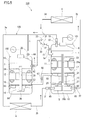
Fig. 7 , the refrigeration cycle apparatus ofPatent Literature 1 includes afirst compressor 92, asecond compressor 93, and athird compressor 94. A refrigerant is supplied to thecompressors main suction pipe 95. Themain suction pipe 95 is provided with a maincurved portion 96 and amain branch portion 97. Themain suction pipe 95 branches at themain branch portion 97 into a firstsuction branch pipe 98 for supplying the refrigerant to thefirst compressor 92 and asuction connection pipe 99 for supplying the refrigerant to thecompressors - The main
curved portion 96 is an elbow pipe connecting an upstream-side pipe with a downstream-side pipe at a right angle. Themain branch portion 97 includes afirst branch passage 97a and asecond branch passage 97b. Thefirst branch passage 97a is located below and outside thesecond branch passage 97b in the radial direction of the maincurved portion 96. That is, thefirst branch passage 97a is provided obliquely below thesecond branch passage 97b at an angle of 45°. The firstsuction branch pipe 98 is connected to thefirst branch passage 97a, and thesuction connection pipe 99 is connected to thesecond branch passage 97b. - During the operation of the refrigeration cycle apparatus, the refrigerant and oil mixed therein flow through the
main suction pipe 95. Gravity and centrifugal force generated in the maincurved portion 96 act on the refrigerant and the oil. There is a density difference between the refrigerant and the oil. Therefore, in the downstream of the maincurved portion 96, the refrigerant flows in the upper and inner part in the radial direction of the maincurved portion 96, and the oil flows in the lower and outer part in the radial direction of the maincurved portion 96. That is, the oil tends to flow into thefirst branch passage 97a, and a relatively large amount of oil is returned to thefirst compressor 92. If there is an excess of oil in thefirst compressor 92, the oil is transferred from thefirst compressor 92 to thesecond compressor 93 and thethird compressor 94 through an oil equalizing pipe. -
Patent Literature 1JP 2007-333376 A - With the pipe arrangement shown in
Fig. 7 , the size of the suction pipes for thecompressors main branch portion 97 is wrong or the connection accuracy of themain branch portion 97 is low, a sufficient effect may not be obtained. - It is an object of the present invention to provide a technique for returning an appropriate amount of oil to each of a plurality of compressors.
- The present invention provides a refrigeration cycle apparatus including: a first compressor having a first compression mechanism, an expansion mechanism, a shaft coupling the first compression mechanism and the expansion mechanism to each other, and a first closed casing accommodating the first compression mechanism, the expansion mechanism, and the shaft; a second compressor having a second compression mechanism disposed in parallel with the first compression mechanism, and a second closed casing accommodating the second compression mechanism; a radiator for cooling a refrigerant compressed by the first compression mechanism and the refrigerant compressed by the second compression mechanism; an evaporator for evaporating the refrigerant expanded by the expansion mechanism; and a pipe branching portion serving as a flow passage for introducing the refrigerant from the evaporator to the first compression mechanism and the second compression mechanism, respectively, the pipe branching portion including an inlet pipe for receiving the refrigerant from the evaporator, a first branch outlet pipe for introducing the refrigerant flowing into the inlet pipe to the first compression mechanism, and a second branch outlet pipe for introducing the refrigerant flowing into the inlet pipe to the second compression mechanism, wherein the inlet pipe and the first branch outlet pipe form an obtuse angle or an angle of 180° therebetween, and the inlet pipe and the second branch outlet pipe form an acute angle therebetween.
- In the present invention mentioned above, the first compressor has the expansion mechanism for recovering power from the refrigerant, in addition to the first compression mechanism for compressing the refrigerant. Therefore, the amount of oil mixed with the refrigerant in the first compressor and discharged to the outside (refrigerant circuit) usually exceeds the amount of oil mixed with the refrigerant in the second compressor and discharged to the outside. In other words, the amount of oil used in the first compressor is greater than the amount of oil used in the second compressor. In such a case, the amount of oil in the first compressor and the amount of oil in the second compressor can be balanced by returning the oil preferentially to the first compressor.
- According to the present invention, the inlet pipe and the first branch outlet pipe form an obtuse angle or an angle of 180° therebetween, and the inlet pipe and the second branch outlet pipe form an acute angle therebetween. With this structure, the liquid phase oil tends to flow to the first branch outlet pipe. That is, the amount of oil returned to the first compressor exceeds the amount of oil returned to the second compressor. As a result, an appropriate amount of oil is always held in each of the first compressor and the second compressor.
Particularly in the case where the present invention is applied to a refrigeration cycle apparatus including first and second compressors having different structures, excellent effects are obtained. -
-
Fig. 1 is a configuration diagram of a refrigeration cycle apparatus according to an embodiment of the present invention. -
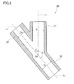
Fig. 2 is an enlarged cross-sectional view of a pipe branching portion shown inFig. 1 . -
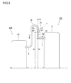
Fig. 3 is a schematic diagram showing a suitable positional relationship between the pipe branching portion and respective compressors. -
Fig. 4 is a schematic diagram showing another structure of the pipe branching portion. -
Fig. 5 is a configuration diagram of a refrigeration cycle apparatus according to a modification. -
Fig. 6A is a cross-sectional view of a valve in a closed position, provided in a suction pipe. -
Fig. 6B is a cross-sectional view of the valve in an open position, provided in the suction pipe. -
Fig. 7 is a perspective view of a pipe arrangement in a conventional refrigeration cycle apparatus including a plurality of compressors. - Hereinafter, an embodiment of the present invention will be described with reference to the drawings. The present invention is not limited to the following embodiment.
- As shown in
Fig. 1 , arefrigeration cycle apparatus 100 of the present embodiment includes afirst compressor 10 1, asecond compressor 102, a radiator 4, and anevaporator 6. These devices are connected byflow passages 3a to 3d so as to form arefrigerant circuit 105. Theflow passages 3a to 3d typically are refrigerant pipes. Therefrigerant circuit 105 is filled with a refrigerant, such as carbon dioxide or hydrofluorocarbon, as a working fluid. - The
first compressor 101 includes a first closedcasing 9, afirst compression mechanism 1, anexpansion mechanism 5, afirst motor 11, afirst oil pump 15, and afirst shaft 23. The axial direction of thefirst shaft 23 is parallel to the vertical direction. Thefirst compression mechanism 1 is disposed in the upper part of the first closedcasing 9. Theexpansion mechanism 5 is disposed in the lower part of the first closedcasing 9. Thefirst motor 11 is disposed between thefirst compression mechanism 1 and theexpansion mechanism 5. Thefirst compression mechanism 1, theexpansion mechanism 5, and thefirst motor 11 are coupled together by thefirst shaft 23. The power recovered from the refrigerant in theexpansion mechanism 5 is transferred to thefirst compression mechanism 1 through thefirst shaft 23. Thereby, the load on thefirst motor 11 is reduced, and thus the efficiency of therefrigeration cycle apparatus 100 is improved. This type of compressor is often called an expander-integrated compressor. The detailed configuration of an expander-integrated compressor is disclosed in, for example,WO 2008/087795 A1 . - The first
closed casing 9 has a cylindrical shape with its upper and lower ends closed. Afirst oil reservoir 13 is formed in the bottom portion of the firstclosed casing 9. Oil for lubricating and sealing thefirst compression mechanism 1 and theexpansion mechanism 5 is held in thefirst oil reservoir 13. Theexpansion mechanism 5 is immersed in the oil in thefirst oil reservoir 13. - In the present embodiment, the
first compression mechanism 1 and theexpansion mechanism 5 are both positive displacement fluid mechanisms. Specifically, thefirst compression mechanism 1 is a scroll compression mechanism, and theexpansion mechanism 5 is a two-stage rotary expansion mechanism. The types of thefirst compression mechanism 1 and theexpansion mechanism 5 are not limited. The types such as a rotary type (including a rolling piston type, a swing type, and a sliding vane type) and a scroll type can be used as appropriate. - In the
first shaft 23,oil supply passages first compression mechanism 1 and theexpansion mechanism 5 through theoil supply passages first compression mechanism 1 and theexpansion mechanism 5 are coupled together by thefirst shaft 23, the rotational speed of thefirst compression mechanism 1 is always equal to that of theexpansion mechanism 5. Thefirst shaft 23 may be composed of a plurality of parts. In this case, a gear, a clutch, a torque converter, or the like may be provided to make the rotational speed of thefirst compression mechanism 1 different from that of theexpansion mechanism 5. - The
first oil pump 15 is disposed between thefirst compression mechanism 1 and theexpansion mechanism 5 to supply the oil in thefirst oil reservoir 13 to thefirst compression mechanism 1. Thefirst oil pump 15 is, for example, a positive displacement oil pump. Thefirst shaft 23 penetrates thefirst oil pump 15 so that thefirst oil pump 15 is driven by thefirst shaft 23. Thefirst oil pump 15 has asuction port 25 opening into thefirst oil reservoir 13. That is, the oil level S1 in thefirst oil reservoir 13 is higher than thesuction port 25. The oil in thefirst oil reservoir 13 is drawn into thefirst oil pump 15 through thesuction port 25, and introduced to theoil supply passage 28a. - The
first motor 11 is mounted coaxially with thefirst shaft 23 between thefirst oil pump 15 and thefirst compression mechanism 1 so as to drive thefirst compression mechanism 1. - A
first bearing member 17 for supporting thefirst shaft 23 is provided between thefirst motor 11 and thefirst oil pump 15. Thefirst bearing member 17 is formed of a flat circular plate, for example, and is fixed to the firstclosed casing 9. Thefirst bearing member 17 also has a function of preventing the oil in thefirst oil reservoir 13 from being agitated by the swirl flow generated by thefirst motor 11. - A
flow suppressing plate 27 is provided between thefirst oil pump 15 and theexpansion mechanism 5. A gap is formed between theflow suppressing plate 27 and the firstclosed casing 9 so that the oil can flow through the gap. The role of theflow suppressing plate 27 mainly is to prevent, as much as possible, the mixing of the oil above theflow suppressing plate 27 and the oil below theflow suppressing plate 27. As theflow suppressing plate 27, for example, a single or a plurality of flat circular plates can be used. The normal direction of theflow suppressing plate 27 is parallel to the axial direction of thefirst shaft 23. Aspacer 42 is provided below theflow suppressing plate 27 to keep a certain distance between theexpansion mechanism 5 and theflow suppressing plate 27. Thespacer 42 may be integrated with another component, for example, with theflow suppressing plate 27. - A
suction pipe 7 and adischarge pipe 19 further are connected to the firstclosed casing 9. Thesuction pipe 7 and thedischarge pipe 19 constitute the branch portions of theflow passage 3d and theflow passage 3a, respectively. Thesuction pipe 7 penetrates the wall (side wall) of the firstclosed casing 9 and is connected to thefirst compression mechanism 1. The refrigerant is drawn directly into thefirst compression mechanism 1 not through the internal space of the firstclosed casing 9 but through thesuction pipe 7. Thedischarge pipe 19 penetrates the wall (upper wall) of the firstclosed casing 9 and opens into the internal space of the firstclosed casing 9. In the present embodiment, the refrigerant compressed by thefirst compression mechanism 1 is discharged into the internal space of the firstclosed casing 9, flows through the internal space, and then is introduced to the radiator 4 through thedischarge pipe 19. That is, thefirst compressor 101 belongs to a high pressure shell type compressor in which the internal space of the firstclosed casing 9 is filled with compressed refrigerant. - Generally, a high pressure shell type compressor is advantageous in reducing the amount of oil discharged from the compressor because the oil mixed in the refrigerant can be separated from the refrigerant by the gravity of the oil or the centrifugal force generated by the motor. Furthermore, since the heat of the motor can be transferred to the refrigerant, the heating capacity is increased.
- A
suction pipe 21 and adischarge pipe 22 further are connected to the firstclosed casing 9. Thesuction pipe 21 and thedischarge pipe 22 each penetrate the wall (side wall) of the firstclosed casing 9 and are connected to theexpansion mechanism 5. The refrigerant is drawn directly into theexpansion mechanism 5 not through the internal space of the firstclosed casing 9 but through thesuction pipe 21. The expanded refrigerant is discharged directly to the outside of the firstclosed casing 9 through thedischarge pipe 22, and introduced to theevaporator 6. - The
second compressor 102 includes a secondclosed casing 10, asecond compression mechanism 2, asecond motor 12, asecond oil pump 16, and asecond shaft 24. The axial direction of thesecond shaft 24 is parallel to the vertical direction. Thesecond compression mechanism 2 is disposed in the upper part of the secondclosed casing 10. Thesecond compression mechanism 2, thesecond motor 12, and thesecond oil pump 16 are placed in this order from the top. - The second
closed casing 10 has a cylindrical shape with its upper and lower ends closed. The area of the horizontal cross section of the secondclosed casing 10 is equal to, for example, the area of the horizontal cross section of the firstclosed casing 9. Asecond oil reservoir 14 is formed in the bottom portion of the secondclosed casing 10. Oil for lubricating and sealing thesecond compression mechanism 2 is held in thesecond oil reservoir 14. The height of the bottom surface of the secondclosed casing 10 is equal to, for example, the height of the bottom surface of the firstclosed casing 9 in the vertical direction. However, the positional relationship between theclosed casings closed casings first compression mechanism 1 coincides with the position of thesecond compression mechanism 2 in the vertical direction. - In the present embodiment, the
second compression mechanism 2 also is a positive displacement fluid mechanism. Specifically, thesecond compression mechanism 2 is a scroll compression mechanism. Like thefirst compression mechanism 1, the type of thesecond compression mechanism 2 also is not limited. The volumetric capacity of thesecond compression mechanism 2 may be equal to or different from that of thefirst compression mechanism 1. However, thesecond compression mechanism 2 of the same type and the same volumetric capacity as those of thefirst compression mechanism 1 is very advantageous in terms of cost and controllability. - The
second shaft 24 couples thesecond compression mechanism 2 coaxially with thesecond motor 12 for driving thesecond compression mechanism 2. In thesecond shaft 24, anoil supply passage 29 extending in the axial direction is formed. Thesecond oil pump 16 is disposed at the end (lower end) of thesecond shaft 24 to supply the oil in thesecond oil reservoir 14 to thesecond compression mechanism 2. Thesecond oil pump 16 is, for example, a positive displacement or centrifugal oil pump. Thesecond oil pump 16 has asuction port 26 opening into thesecond oil reservoir 14. That is, the oil level S2 in thesecond oil reservoir 14 is higher than thesuction port 26. The oil in thesecond oil reservoir 14 is drawn into thesecond oil pump 16 through thesuction port 26, and introduced to theoil supply passage 29. The oil is supplied to thesecond compression mechanism 2 through theoil supply passage 29. - A
second bearing member 18 for supporting the lower part of thesecond shaft 24 is provided between thesecond motor 12 and thesecond oil pump 16. Thesecond bearing member 18 is formed of a flat circular plate, for example, and is fixed to the secondclosed casing 10. Thesecond bearing member 18 also has a function of preventing the oil in thesecond oil reservoir 14 from being agitated by the swirl flow generated by thesecond motor 12. - A
suction pipe 8 and adischarge pipe 20 further are connected to the secondclosed casing 10. Thesuction pipe 8 and thedischarge pipe 20 constitute the branch portions of theflow passage 3d and theflow passage 3a, respectively. Thesuction pipe 8 penetrates the wall (side wall) of the secondclosed casing 10 and is connected to thesecond compression mechanism 2. The refrigerant is drawn directly into thesecond compression mechanism 2 not through the internal space of the secondclosed casing 10 but through thesuction pipe 8. Thedischarge pipe 20 penetrates the wall (upper wall) of the secondclosed casing 10 and opens into the internal space of the secondclosed casing 10. In the present embodiment, the refrigerant compressed by thesecond compression mechanism 2 is discharged into the internal space of the secondclosed casing 10, flows through the internal space, and then is introduced to the radiator 4 through thedischarge pipe 20. That is, thesecond compressor 102 belongs to a high pressure shell type compressor in which the internal space of the secondclosed casing 10 is filled with compressed refrigerant. - In the
refrigerant circuit 105, thesecond compression mechanism 2 is disposed in parallel with thefirst compression mechanism 1. Thedischarge pipe 19 serves as a discharge passage for introducing the refrigerant compressed by thefirst compression mechanism 1 from the internal space of the firstclosed casing 9 to the radiator 4. Likewise, thedischarge pipe 20 serves as a discharge passage for introducing the refrigerant compressed by thesecond compression mechanism 2 from the internal space of the secondclosed casing 10 to the radiator 4. More specifically, thedischarge pipe 19 and thedischarge pipe 20 constitute the branch portions of theflow passage 3a for introducing the compressed refrigerant to the radiator 4. Thesuction pipe 7 and thesuction pipe 8 constitute the branch portions of theflow passage 3d for introducing the refrigerant to be compressed to thefirst compression mechanism 1 and thesecond compression mechanism 2, respectively. Therefore, the refrigerant is evaporated in theevaporator 6 and then compressed by either thefirst compression mechanism 1 or thesecond compression mechanism 2. The refrigerant compressed by thefirst compression mechanism 1 and the refrigerant compressed by thesecond compression mechanism 2 are merged together and flow into the radiator 4. The internal space of the firstclosed casing 9 and the internal space of the secondclosed casing 10 are in communication with each other through thedischarge pipe 19 and thedischarge pipe 20. That is, thedischarge pipe 19 and thedischarge pipe 20 serve also as pressure equalizing pipes. - Specifically, a
pipe branching portion 30 is provided in theflow passage 3d for introducing the refrigerant from theevaporator 6 to thefirst compression mechanism 1 and thesecond compression mechanism 2, respectively. Thepipe branching portion 30 is a pipe called a "Y-junction tube" with one inlet and two outlets. In the present embodiment, a Y-junction tube having an asymmetrical shape is used as thepipe branching portion 30. - As shown in
Fig. 1 andFig. 2 , thepipe branching portion 30 includes aninlet pipe 31, a firstbranch outlet pipe 32, and a secondbranch outlet pipe 33. Theinlet pipe 31 is a portion for receiving the refrigerant from theevaporator 6. The firstbranch outlet pipe 32 is a portion for introducing the refrigerant flowing into theinlet pipe 31 to thefirst compression mechanism 1. The secondbranch outlet pipe 33 is a portion for introducing the refrigerant flowing into theinlet pipe 31 to thesecond compression mechanism 2. The angle α (first branch angle) between theinlet pipe 31 and the firstbranch outlet pipe 32 is an obtuse angle. The angle β (second branch angle) between theinlet pipe 31 and the secondbranch outlet pipe 33 is an acute angle. - During the operation of the
refrigeration cycle apparatus 100, the refrigerant is compressed by thefirst compression mechanism 1 or thesecond compression mechanism 2. The compressed refrigerant is introduced to the radiator 4 through theflow passage 3a. At this time, a part of the oil in thefirst oil reservoir 13 is mixed into the compressed refrigerant and flows outside the firstclosed casing 9. Likewise, a part of the oil in thesecond oil reservoir 14 is mixed into the compressed refrigerant and flows outside the secondclosed casing 10. The refrigerant is cooled in the radiator 4, and then introduced into theexpansion mechanism 5 through theflow passage 3b. - The
expansion mechanism 5 expands the refrigerant and recovers power from the refrigerant. The expanded refrigerant is introduced into theevaporator 6 through theflow passage 3c. At this time, a part of the oil in thefirst oil reservoir 13 is mixed into the expanded refrigerant and flows outside the firstclosed casing 9. In thefirst compressor 10 1, the oil is mixed into the refrigerant in both of thefirst compression mechanism 1 and theexpansion mechanism 5. In thesecond compressor 102, the oil is mixed into the refrigerant only in thesecond compression mechanism 2. Therefore, the amount of oil taken out of thefirst oil reservoir 13 is usually greater than the amount of oil taken out of thesecond oil reservoir 14. - The refrigerant is evaporated in the
evaporator 6, and then introduced into theinlet pipe 31 of thepipe branching portion 30 through theflow passage 3d. In thepipe branching portion 30, the refrigerant is in the gas phase, and the oil is in the liquid phase. Since the angle α, is greater than the angle β, the pressure drop gradient caused by the flow of the refrigerant and oil from theinlet pipe 31 to the secondbranch outlet pipe 33 is larger than that caused by the flow of the refrigerant and oil from theinlet pipe 31 to the firstbranch outlet pipe 32. As stated herein, the "pressure drop gradient" means a pressure gradient based on a pressure drop. - In general terms, when a gas-liquid two-phase flow containing a gas phase fluid and a liquid phase fluid branches in two directions having different pressure drop gradients, the gas phase fluid tends to flow toward the greater pressure drop gradient side. Assuming that the same amount of gas phase fluid and liquid phase fluid flow in the same flow passage, the pressure drop of the gas phase fluid is greater than that of the liquid phase fluid. Therefore, in the case where the pressure drop gradients in the two directions are different from each other, more gas phase fluid flows toward the greater pressure drop gradient side while more liquid phase fluid flows toward the smaller pressure drop gradient side to maintain the balance of the pressure drop in the two directions.
- For example, Asano, et al. have conducted experiments for the separation of an air-water two-phase flow using a plurality of Y junction tubes with different branch angles, and reported the results of the experiments ("A Study of the Phase Separation Characteristics in Gas-Liquid Two-Phase Flows by an Impacting Y-Junction", 1st Report, Journal of the Japan Society of Mechanical Engineers (Series B), Vol. 67, No. 654, pp. 350-355). As a result of these experiments for the flow separation, Asano, et al. have confirmed that the phase separation performance is enhanced as the branch angle 6 (corresponding to the second branch angle β in the present embodiment) decreases in the range of 30° to 90°. This result coincides with the fact that the liquid phase to which a greater inertial force is applied is more likely to go straight ahead as the branch angle θ of a Y-junction tube decreases. This result also shows that more gas phase fluid flows toward the greater pressure drop gradient side and more liquid phase fluid flows toward the smaller pressure drop gradient side.
- In the present embodiment, the
compression mechanisms pipe branching portion 30, and the flow rates of the refrigerant in thebranch outlet pipes compression mechanisms pipe branching portion 30, although the phenomenon in thepipe branching portion 30 cannot always be explained just in general terms above. - An inertial force acting on a liquid phase oil is greater than that acting on a gas phase refrigerant. In the present embodiment, since the angle α between the
inlet pipe 31 and the firstbranch outlet pipe 32 is greater than the angle β between theinlet pipe 31 and the secondbranch outlet pipe 33, the oil tends to flow into the firstbranch outlet pipe 32. - Due to the influences of pressure drops and inertial forces, as described above, the proportion of oil flowing from the
inlet pipe 31 into the firstbranch outlet pipe 32 is higher than that flowing from theinlet pipe 31 into the secondbranch outlet pipe 33. This means that a relatively large amount of oil is returned to thefirst compressor 10 1, and a relatively small amount of oil is returned to thesecond compressor 102. Thepipe branching portion 30 can be constructed so that the ratio between the amount of oil flowing into the firstbranch outlet pipe 32 and the amount of oil flowing into the second branch outlet pipe 33 (distribution ratio of oil) falls within, for example, the range of 6:4 to 9:1 when thefirst compression mechanism 1 and thesecond compression mechanism 2 have the same volumetric capacity and the same rotational speed, although it depends on other various conditions. - As described above, during the operation of the
refrigeration cycle apparatus 100, the amount of oil taken out of thefirst oil reservoir 13 is greater than the amount of oil taken out of thesecond oil reservoir 14. However, the oil distribution function of thepipe branching portion 30 makes it possible to return more oil to thefirst compression mechanism 101 than to thesecond compression mechanism 102. As a result, the difference in the amount of oil taken can be balanced out, and the oil levels S1 and S2 in the compressors can be maintained approximately constant. Even with the passage of the operation time, an imbalance does not occur between the amount of oil in thefirst oil reservoir 13 and that in thesecond oil reservoir 14, and an appropriate amount of oil can always be held in each of theoil reservoirs refrigeration cycle apparatus 100 also is enhanced. - Next, the structure of the
pipe branching portion 30 is described in further detail. - In the example shown in
Fig. 1 andFig. 2 , the angle α is set to an obtuse angle. When the angle α is an obtuse angle, the angle α is, for example, in the range of 100° to 170°, and preferably in the range of 120° to 160°. The angle β is, for example, in the range of 10° to 60°, and preferably in the range of 20° to 40°. When the angle α and the angle β are set in these ranges, it is certainly possible to allow more oil to flow into the firstbranch outlet pipe 32 than into the secondbranch outlet pipe 33. In the example shown inFig. 2 , the angle α is 150°, and the angle β is 30°. - Furthermore, when the first
branch outlet pipe 32 and the secondbranch outlet pipe 33 are located on the same straight line, as in the present embodiment, the firstbranch outlet pipe 32 and the secondbranch outlet pipe 33 can be formed of a single pipe. As a result, the structure of thepipe branching portion 30 is simplified, and therefore variations in the quality are reduced in mass production and a desired effect is obtained stably. - The angle α can be defined as an angle between the center line L1 of the
inlet pipe 31 and the center line L2 of the firstbranch outlet pipe 32. Likewise, the angle β can be defined as an angle between the center line L1 of theinlet pipe 31 and the center line L3 of the secondbranch outlet pipe 32. More precisely, the angle between the center line L1 and the center line L2 on a plane including the center line L1 and the center line L2 is regarded as the angle α. Likewise, the angle between the center line L1 and the center line L3 on a plane including the center line L1 and the center line L3 is regarded as the angle β. - In the present embodiment, since the first
branch outlet pipe 32 and the secondbranch outlet pipe 33 are located on the same straight line, the center line L2 coincides with the center line L3. That is, the center line L1 of theinlet pipe 31 and the center line L2 of the firstbranch outlet pipe 32 are located on the same plane, and the center line L1 of theinlet pipe 31 and the center line L3 of the secondbranch outlet pipe 33 are located on the same plane. Therefore, the center line L1, the center line L2, and the center line L3 are located on the same plane. Theinlet pipe 31, the firstbranch outlet pipe 32, and the secondbranch outlet pipe 33 each do not necessarily be formed of a straight pipe. These pipes may each be formed of a curved pipe. - In the present embodiment, the first
branch outlet pipe 32 extends downwardly and the secondbranch outlet pipe 33 extends upwardly in the vertical direction. When thepipe branching portion 30 is mounted in such a posture, oil is allowed to flow into the firstbranch outlet pipe 32 more easily under the influence of gravity. Even if thepipe branching portion 30 is disposed in any posture, of course, the oil distribution function of thepipe branching portion 30 is sufficiently fulfilled. - In the example shown in
Fig. 1 andFig. 2 , the center line L1 of theinlet pipe 31 is parallel to the vertical direction, and the center lines L2 and L3 of thebranch outlet pipes first compression mechanism 1 formed in the firstclosed casing 9 is located below the branch point CP of thepipe branching portion 30 in the vertical direction. This positional relationship eliminates the need for a U-shaped portion between thepipe branching portion 30 and the inlet port of thefirst compression mechanism 1, and therefore the oil can be smoothly introduced into thefirst compression mechanism 1. Furthermore, there is no need to consider the stagnation of oil in such a U-shaped portion. -
Fig. 3 shows another example of the mounting of thepipe branching portion 30. In this example, the center line L2 of the firstbranch outlet pipe 32 is parallel to the vertical direction, and the center line L1 of theinlet pipe 31 is inclined at a predetermined angle (90° - angle β) with respect to the horizontal direction. When the bottom surface of the firstclosed casing 9 is a reference plane, the height h1 from the reference plane to the branch point CP is greater than the height h2 from the reference plane to a joint between thesuction pipe 7 and the firstclosed casing 9. The flow passage from thepipe branching portion 30 to a joint between thesuction pipe 8 and the secondclosed casing 10 includes aU-shaped portion 35. Compared to the structure shown inFig. 1 andFig. 2 , this structure allows a higher proportion of oil to be returned to thefirst compressor 101, and therefore it is effective if more oil is expected to be returned to thefirst compressor 101. - The angle α may be 180°. That is, in the
pipe branching portion 30a shown inFig. 4 , theinlet pipe 31 and the firstbranch outlet pipe 32 are located on the same straight line. The angle β between theinlet pipe 31 and the secondbranch outlet pipe 33 is an acute angle. Thispipe branching portion 30a also allows the oil distribution function to be fulfilled, and the oil can be returned to thefirst compressor 101 preferentially. - The cross sectional shapes and dimensions of the pipes that constitute the
pipe branching portion 30 are not particularly limited. In the present embodiment, theinlet pipe 31, the firstbranch outlet pipe 32, and the secondbranch outlet pipe 33 each have a circular cross section. The firstbranch outlet pipe 32 has a larger flow passage area than that of the secondbranch outlet pipe 33. Specifically, as shown inFig. 2 , the inner diameter D2 of the firstbranch outlet pipe 32 is larger than the inner diameter D3 of the secondbranch outlet pipe 33. With this structure, the pressure drop gradient caused by the flow of the refrigerant and oil to the secondbranch outlet pipe 33 becomes much larger. Therefore, the oil tends to flow into the firstbranch outlet pipe 32, compared with the case where the inner diameter D2 is equal to the inner diameter D3. - The dimensional ratio between the inner diameter D2 and the inner diameter D3 is not particularly limited. For example, it can be set as appropriate within the range of D2:D3 = 1.5:1 to 3:1. In the present embodiment, the inner diameter D1 of the
inlet pipe 31 is equal to the inner diameter D2 of the firstbranch outlet pipe 32. - Examples of oils that can be used in the
refrigeration cycle apparatus 100 include ester oil (such as polyol ester oil), carbonate oil, polyalkylene glycol (PAG) oil, and polyvinyl ether (PVE) oil. Since these oils are significantly different in specific gravity from the gas phase refrigerant, they can be used without any problem. - As shown in
Fig. 1 , in the present embodiment, the firstclosed casing 9 is connected to the secondclosed casing 10 by anoil equalizing pipe 50. Theopening 51 of theoil equalizing pipe 50 in the firstclosed casing 9 is located between thesuction port 25 of thefirst oil pump 15 and thefirst motor 11 in the axial direction of thefirst shaft 23. Specifically, theopening 51 is located in the vicinity of the lower surface of thefirst bearing member 17 between thesuction port 25 and thefirst bearing member 17. On the other hand, theopening 52 of theoil equalizing pipe 50 in the secondclosed casing 10 is located between thesuction port 26 of thesecond oil pump 16 and thesecond motor 12 in the axial direction of thesecond shaft 24. Specifically, theopening 52 is located in the vicinity of the upper surface of thesecond bearing member 18 between thesecond bearing member 18 and thesecond motor 12. - With the
oil equalizing pipe 50, when there is an excess of oil in thefirst oil reservoir 13, the excess oil automatically moves from thefirst oil reservoir 13 to thesecond oil reservoir 14. That is, the amounts of oil are automatically balanced. Specifically, when theoil level S 1 of thefirst oil reservoir 13 reaches theopening 51, the oil flows from thefirst oil reservoir 13 to thesecond oil reservoir 14. The oil level S1 of thefirst oil reservoir 13 is always maintained at the lower end of theopening 51. The oil level S2 of thesecond oil reservoir 14 is always maintained slightly below thesecond bearing member 18. With a combined use of thisoil equalizing pipe 50 and thepipe branching portion 30, there is no need to change the dimensions and shape of thepipe branching portion 30 according to the specifications of thefirst compressor 101 and thesecond compressor 102. Theoil equalizing pipe 50 can be eliminated, of course. - Furthermore, the temperature of the oil flowing from the
first oil reservoir 13 to thesecond oil reservoir 14 through theoil equalizing pipe 50 is relatively high. When high temperature oil moves from thefirst oil reservoir 13 to thesecond oil reservoir 14, it is easy to maintain the state in which relatively low temperature oil is retained around theexpansion mechanism 5. That is, the heat transfer between thefirst compression mechanism 1 and theexpansion mechanism 5 through the oil can be suppressed. Thereby, an increase in the temperature of the expanded refrigerant and a decrease in the temperature of the compressed refrigerant can be prevented, and as a result, the efficiency of therefrigeration cycle apparatus 100 also is enhanced. - As shown in
Fig. 5 , various valves may be provided on therefrigerant circuit 105. Specifically, avalve 61, avalve 62, avalve 63, and avalve 64 are provided in thesuction pipe 7, thesuction pipe 8, thedischarge pipe 19, and thedischarge pipe 20, respectively. Avalve 65 and avalve 66 are provided in thesuction pipe 21 and thedischarge pipe 22, respectively, on theexpansion mechanism 5 side. Avalve 67 is provided in theoil equalizing pipe 50. Thesevalves 61 to 67 can be used to prevent air and moisture from entering therefrigerant circuit 105 when thefirst compressor 101 or thesecond compressor 102 is insulated (separated) from therefrigerant circuit 105 for the maintenance, for example. Furthermore, thevalves second compressor 102 from therefrigerant circuit 105 when therefrigeration cycle apparatus 100 is operated using only thefirst compressor 101. - The
valve 61 is provided in thesuction pipe 7, that is, in the suction passage communicating thepipe branching portion 30 and the inlet port of thefirst compression mechanism 1. As thevalve 61, a valve including no pressure reducing portion, such as a throttle, can be used. In this case, the internal flow passage of thevalve 61 has a constant area throughout the passage between the inlet and the outlet of thevalve 61 when it is fully opened. Thisvalve 61 can be a ball valve, for example. As shown inFig. 6A , thevalve 61 includes ahousing 76 having an in-valve flow passage 70 (internal flow passage), and aball 74 disposed in thehousing 76 so as to partition the in-valve flow passage 70 into an upstream side and a downstream side. When thevalve 61 is closed, theball 74 closes the in-valve flow passage 70. On the other hand, as shown inFig. 6B , when thevalve 61 is opened, theball 74 is rotated 90° and a through-hole 72 formed in theball 74 faces the in-valve flow passage 70. The through-hole 72 has the same cross sectional area as the in-valve flow passage 70. - With this
valve 61 in thesuction pipe 7, the oil flowing into thesuction pipe 7 through the firstbranch outlet pipe 32 can flow smoothly into the first compressor 101 (more specifically, into the first compression mechanism 1) without stagnating in thevalve 61. This is significant in returning an appropriate amount of oil to thefirst compressor 101, and contributes to the improvement of the reliability of therefrigeration cycle apparatus 100. Valves similar to thevalve 61 can also be used for theother valves 62 to 67. - Furthermore, in the modification shown in
Fig. 5 , thesuction pipe 7 serving as a suction passage communicating thepipe branching portion 30 with the inlet port of thefirst compression mechanism 1 includes aportion 7a (referred to as a vertical portion) parallel to the vertical direction. Thevalve 61 is provided in thisvertical portion 7a. One end of thevertical portion 7a is connected to the firstbranch outlet pipe 32 of thepipe branching portion 30. On the other hand, the other end of thevertical portion 7a is inserted into the firstclosed casing 9 so as to be connected to thefirst compression mechanism 1. The oil flows into thesuction pipe 7 through thepipe branching portion 30 and further flows downwardly through thevertical portion 7a. Therefore, even if thevalve 61 has a pressure reducing portion such as a throttle and the oil can stagnate temporarily in thevalve 61, the oil can flow out of thevalve 61 by its own gravity so as to flow into thefirst compressor 101. - The present invention can also be applied to a refrigeration cycle apparatus in which the
expansion mechanism 5 is eliminated from thefirst compressor 101, that is, a refrigeration cycle apparatus including a plurality of standard compressors. - The refrigeration cycle apparatus of the present invention can be used for apparatuses such as a water heater, a hot water heating apparatus, and an air conditioner.
Claims (8)
- A refrigeration cycle apparatus comprising:a first compressor having a first compression mechanism, an expansion mechanism, a shaft coupling the first compression mechanism and the expansion mechanism to each other, and a first closed casing accommodating the first compression mechanism, the expansion mechanism, and the shaft;a second compressor having a second compression mechanism disposed in parallel with the first compression mechanism, and a second closed casing accommodating the second compression mechanism;a radiator for cooling a refrigerant compressed by the first compression mechanism and the refrigerant compressed by the second compression mechanism;an evaporator for evaporating the refrigerant expanded by the expansion mechanism; anda pipe branching portion serving as a flow passage for introducing the refrigerant from the evaporator to the first compression mechanism and the second compression mechanism, respectively, the pipe branching portion including an inlet pipe for receiving the refrigerant from the evaporator, a first branch outlet pipe for introducing the refrigerant flowing into the inlet pipe to the first compression mechanism, and a second branch outlet pipe for introducing the refrigerant flowing into the inlet pipe to the second compression mechanism, wherein the inlet pipe and the first branch outlet pipe form an obtuse angle or an angle of 180° therebetween, and the inlet pipe and the second branch outlet pipe form an acute angle therebetween.
- The refrigeration cycle apparatus according to claim 1, wherein the angle formed between the inlet pipe and the first branch outlet pipe is an obtuse angle.
- The refrigeration cycle apparatus according to claim 1 or 2, wherein the first branch outlet pipe and the second branch outlet pipe are located on the same straight line.
- The refrigeration cycle apparatus according to any one of claims 1 to 3, wherein the first branch outlet pipe extends downwardly and the second branch outlet pipe extends upwardly in a vertical direction.
- The refrigeration cycle apparatus according to any one of claims 1 to 4, wherein an inlet port of the first compression mechanism formed in the first closed casing is located below a branch point of the pipe branching portion in a vertical direction.
- The refrigeration cycle apparatus according to any one of claims 1 to 5, wherein the first branch outlet pipe has a larger flow passage area than that of the second branch outlet pipe.
- The refrigeration cycle apparatus according to any one of claims 1 to 6, further comprising a valve provided in a suction passage communicating the pipe branching portion with an inlet port of the first compression mechanism, wherein
an internal flow passage of the valve has a constant area throughout the passage between an inlet and an outlet of the valve when the valve is opened. - The refrigeration cycle apparatus according to claim 7, wherein the suction passage includes a portion parallel to a vertical direction, and the valve is provided in the portion.
Applications Claiming Priority (2)
| Application Number | Priority Date | Filing Date | Title |
|---|---|---|---|
| JP2009131277 | 2009-05-29 | ||
| PCT/JP2010/003452 WO2010137274A1 (en) | 2009-05-29 | 2010-05-21 | Refrigeration cycle device |
Publications (1)
| Publication Number | Publication Date |
|---|---|
| EP2437006A1 true EP2437006A1 (en) | 2012-04-04 |
Family
ID=43222402
Family Applications (1)
| Application Number | Title | Priority Date | Filing Date |
|---|---|---|---|
| EP10780235A Withdrawn EP2437006A1 (en) | 2009-05-29 | 2010-05-21 | Refrigeration cycle device |
Country Status (5)
| Country | Link |
|---|---|
| US (1) | US20120017636A1 (en) |
| EP (1) | EP2437006A1 (en) |
| JP (1) | JPWO2010137274A1 (en) |
| CN (1) | CN102369401A (en) |
| WO (1) | WO2010137274A1 (en) |
Families Citing this family (9)
| Publication number | Priority date | Publication date | Assignee | Title |
|---|---|---|---|---|
| EP2177760A1 (en) * | 2008-05-23 | 2010-04-21 | Panasonic Corporation | Fluid machine and refrigeration cycle device |
| FR2991733B1 (en) * | 2012-06-12 | 2016-09-02 | Danfoss Commercial Compressors | COMPRESSION DEVICE AND THERMODYNAMIC SYSTEM COMPRISING SUCH A COMPRESSION DEVICE |
| US9689386B2 (en) * | 2012-07-31 | 2017-06-27 | Bitzer Kuehlmaschinenbau Gmbh | Method of active oil management for multiple scroll compressors |
| US10634137B2 (en) | 2012-07-31 | 2020-04-28 | Bitzer Kuehlmaschinenbau Gmbh | Suction header arrangement for oil management in multiple-compressor systems |
| JP6087610B2 (en) * | 2012-12-14 | 2017-03-01 | シャープ株式会社 | Air conditioner |
| US9869497B2 (en) | 2013-04-03 | 2018-01-16 | Carrier Corporation | Discharge manifold for use with multiple compressors |
| ITUB20150727A1 (en) | 2015-05-22 | 2016-11-22 | Nuovo Pignone Tecnologie Srl | COOLING SYSTEM FOR AN INTEGRATED MOTORCOMPRESSOR. |
| CN113154723B (en) * | 2015-12-17 | 2022-11-04 | 特灵国际有限公司 | Suction line flow control for lubricant management |
| EP3862612A1 (en) * | 2020-02-04 | 2021-08-11 | Carrier Corporation | Fluid equalisation for multiple compressors |
Family Cites Families (16)
| Publication number | Priority date | Publication date | Assignee | Title |
|---|---|---|---|---|
| US3234754A (en) * | 1963-02-18 | 1966-02-15 | Lester K Quick | Reevaporator system for hot gas refrigeration defrosting systems |
| US3386262A (en) * | 1966-10-31 | 1968-06-04 | Trane Co | Refrigeration apparatus with compressors in parallel |
| JPH0737105Y2 (en) * | 1989-05-09 | 1995-08-23 | 三菱重工業株式会社 | Refrigeration air conditioner |
| GB2309748B (en) * | 1996-01-31 | 1999-08-04 | Univ City | Deriving mechanical power by expanding a liquid to its vapour |
| AU2002363131A1 (en) * | 2001-10-29 | 2003-05-12 | Thomas H. Hebert | Multiple compressor common circuit structure design |
| JP3952951B2 (en) * | 2003-01-08 | 2007-08-01 | ダイキン工業株式会社 | Refrigeration equipment |
| CN1816696B (en) * | 2003-07-28 | 2010-04-28 | 大金工业株式会社 | Scroll Fluid Machinery |
| JP4129921B2 (en) * | 2003-12-25 | 2008-08-06 | 三星電子株式会社 | Oil equalization method for multiple compressors |
| KR20050066352A (en) * | 2003-12-26 | 2005-06-30 | 삼성전자주식회사 | Refrigerating cycle system |
| US6983622B2 (en) * | 2004-04-20 | 2006-01-10 | Danfoss Commercial Compressors | Gas distribution device |
| US8109116B2 (en) * | 2005-08-26 | 2012-02-07 | Mitsubishi Electric Corporation | Dual compressor air conditioning system with oil level regulation |
| JP4736727B2 (en) * | 2005-11-11 | 2011-07-27 | ダイキン工業株式会社 | Heat pump water heater |
| JP2008039237A (en) * | 2006-08-03 | 2008-02-21 | Matsushita Electric Ind Co Ltd | Refrigeration cycle equipment |
| FR2909421B1 (en) * | 2006-12-04 | 2009-01-16 | Danfoss Commercial Compressors | SUCTION GAS DISTRIBUTION DEVICE FOR MOUNTING COMPRESSORS IN PARALLEL, AND MOUNTING COMPRESSORS IN PARALLEL |
| JP4162708B2 (en) | 2007-01-15 | 2008-10-08 | 松下電器産業株式会社 | Expander integrated compressor |
| JP2007333376A (en) | 2007-08-20 | 2007-12-27 | Daikin Ind Ltd | Refrigeration equipment |
-
2010
- 2010-05-21 EP EP10780235A patent/EP2437006A1/en not_active Withdrawn
- 2010-05-21 JP JP2011515873A patent/JPWO2010137274A1/en not_active Withdrawn
- 2010-05-21 US US13/262,119 patent/US20120017636A1/en not_active Abandoned
- 2010-05-21 CN CN2010800144046A patent/CN102369401A/en active Pending
- 2010-05-21 WO PCT/JP2010/003452 patent/WO2010137274A1/en not_active Ceased
Non-Patent Citations (1)
| Title |
|---|
| See references of WO2010137274A1 * |
Also Published As
| Publication number | Publication date |
|---|---|
| WO2010137274A1 (en) | 2010-12-02 |
| JPWO2010137274A1 (en) | 2012-11-12 |
| US20120017636A1 (en) | 2012-01-26 |
| CN102369401A (en) | 2012-03-07 |
Similar Documents
| Publication | Publication Date | Title |
|---|---|---|
| EP2437006A1 (en) | Refrigeration cycle device | |
| US8408024B2 (en) | Fluid machine and refrigeration cycle apparatus | |
| US7918096B2 (en) | Refrigeration system | |
| EP2778569B1 (en) | Air conditioner | |
| CN104619988A (en) | Oil equalization configuration for multiple compressor systems containing three or more compressors | |
| CN103486768A (en) | Compression device, and thermodynamic system comprising such compression device | |
| CN102102668A (en) | Rotary compressor | |
| US10941772B2 (en) | Suction line arrangement for multiple compressor system | |
| WO2015029204A1 (en) | Air conditioner | |
| JP4455546B2 (en) | High pressure shell type compressor and refrigeration system | |
| US11649996B2 (en) | System and method for OCR control in paralleled compressors | |
| CN216557747U (en) | Compressor assembly, air condensing units and air conditioning system | |
| US11306953B2 (en) | Compressor and refrigeration cycle apparatus | |
| JP2004301461A (en) | Air conditioner | |
| CN116538093A (en) | Compressor and refrigeration equipment | |
| JP2002277079A (en) | Refrigeration cycle | |
| CN112747501B (en) | Compressor components, heat exchange systems and electrical equipment | |
| CN119934027B (en) | Pump body assembly, vertical compressor and air conditioner | |
| JP7839438B2 (en) | Refrigeration cycle equipment | |
| JPS6030494A (en) | Full enclosed compressor | |
| JP2010084954A (en) | Refrigerating cycle device | |
| JP2024157942A (en) | Positive displacement compressor and refrigerator | |
| CN119491820A (en) | Electric compressors, air conditioning systems and vehicles | |
| CN120292074A (en) | Compression devices and heat exchange systems | |
| CN119778917A (en) | Condenser vessel, system and method for separating oil from an oil-refrigerant mixture |
Legal Events
| Date | Code | Title | Description |
|---|---|---|---|
| PUAI | Public reference made under article 153(3) epc to a published international application that has entered the european phase |
Free format text: ORIGINAL CODE: 0009012 |
|
| 17P | Request for examination filed |
Effective date: 20111229 |
|
| AK | Designated contracting states |
Kind code of ref document: A1 Designated state(s): AL AT BE BG CH CY CZ DE DK EE ES FI FR GB GR HR HU IE IS IT LI LT LU LV MC MK MT NL NO PL PT RO SE SI SK SM TR |
|
| DAX | Request for extension of the european patent (deleted) | ||
| STAA | Information on the status of an ep patent application or granted ep patent |
Free format text: STATUS: THE APPLICATION HAS BEEN WITHDRAWN |
|
| 18W | Application withdrawn |
Effective date: 20131022 |