EP2436994A2 - Outdoor unit and air-conditioning apparatus having the same - Google Patents
Outdoor unit and air-conditioning apparatus having the same Download PDFInfo
- Publication number
- EP2436994A2 EP2436994A2 EP11182449A EP11182449A EP2436994A2 EP 2436994 A2 EP2436994 A2 EP 2436994A2 EP 11182449 A EP11182449 A EP 11182449A EP 11182449 A EP11182449 A EP 11182449A EP 2436994 A2 EP2436994 A2 EP 2436994A2
- Authority
- EP
- European Patent Office
- Prior art keywords
- top panel
- outdoor unit
- casing
- appentice
- overhung
- Prior art date
- Legal status (The legal status is an assumption and is not a legal conclusion. Google has not performed a legal analysis and makes no representation as to the accuracy of the status listed.)
- Granted
Links
- 238000004378 air conditioning Methods 0.000 title description 14
- 238000003780 insertion Methods 0.000 claims description 11
- 230000037431 insertion Effects 0.000 claims description 11
- 230000002093 peripheral effect Effects 0.000 claims description 3
- XLYOFNOQVPJJNP-UHFFFAOYSA-N water Substances O XLYOFNOQVPJJNP-UHFFFAOYSA-N 0.000 description 9
- 238000007789 sealing Methods 0.000 description 6
- 230000008014 freezing Effects 0.000 description 5
- 238000007710 freezing Methods 0.000 description 5
- 230000002159 abnormal effect Effects 0.000 description 3
- 229910000831 Steel Inorganic materials 0.000 description 2
- 239000003507 refrigerant Substances 0.000 description 2
- 239000010959 steel Substances 0.000 description 2
- 208000027418 Wounds and injury Diseases 0.000 description 1
- 238000007664 blowing Methods 0.000 description 1
- 230000006378 damage Effects 0.000 description 1
- 230000006735 deficit Effects 0.000 description 1
- 238000010438 heat treatment Methods 0.000 description 1
- 230000001771 impaired effect Effects 0.000 description 1
- 208000014674 injury Diseases 0.000 description 1
- 238000004519 manufacturing process Methods 0.000 description 1
- 230000008018 melting Effects 0.000 description 1
- 238000002844 melting Methods 0.000 description 1
- 238000000638 solvent extraction Methods 0.000 description 1
- 238000003466 welding Methods 0.000 description 1
Images


Classifications
-
- F—MECHANICAL ENGINEERING; LIGHTING; HEATING; WEAPONS; BLASTING
- F24—HEATING; RANGES; VENTILATING
- F24F—AIR-CONDITIONING; AIR-HUMIDIFICATION; VENTILATION; USE OF AIR CURRENTS FOR SCREENING
- F24F1/00—Room units for air-conditioning, e.g. separate or self-contained units or units receiving primary air from a central station
- F24F1/06—Separate outdoor units, e.g. outdoor unit to be linked to a separate room comprising a compressor and a heat exchanger
- F24F1/56—Casing or covers of separate outdoor units, e.g. fan guards
Landscapes
- Engineering & Computer Science (AREA)
- Chemical & Material Sciences (AREA)
- Combustion & Propulsion (AREA)
- Mechanical Engineering (AREA)
- General Engineering & Computer Science (AREA)
- Other Air-Conditioning Systems (AREA)
- Air Filters, Heat-Exchange Apparatuses, And Housings Of Air-Conditioning Units (AREA)
Abstract
Description
- The present invention relates to an outdoor unit of an air-conditioning apparatus and an air-conditioning apparatus having the outdoor unit.
- In the outdoor unit of the air-conditioning apparatus, water droplets adhered to a front panel by rain or snow during a heating operation or water droplets generated by melting snow accumulated on the outdoor unit drop along a surface of the front panel and enter between a bell mouth and a fan.
- Then, when the outside temperature is low, the temperature of air blown out by the fan may drop to or below freezing. In such a case, the water droplets that entered between the bell mouth and the fan freeze and, if the quantity of the water droplets is large, ice grows and comes into contact with the fan. Accordingly, there arise problems such as generation of abnormal sounds, or abnormal stop of the outdoor unit due to hindrance of rotation.
- In order to solve the problems as described above, an outdoor unit for an air-conditioning unit in which a bell mouth having an outlet opening for a fan is formed on a casing, an outlet grill is provided on the front side of the bell mouth, and a seal member having a width larger than the diameter of the outlet opening is provided above the outlet opening for sealing a portion between the casing and the outlet opening is proposed (for example, see Japanese Registered Utility Model No.
2510078 Fig. 1 )). - In the outdoor unit for the air-conditioning unit disclosed in Japanese Registered Utility Model No.
2510078 Fig. 1 ), when sealing the portion between the casing and the top portion of the outlet grill with the sealing member, a frame-shaped rim is required on an outer periphery, or at least an upper side of the outlet grill formed by welding steel wires, so that the appearance design is not impaired and, in addition, it is necessary to combine a plate-shaped component to the steel wire portion. Therefore, there arise problems of complicated manufacture and increase in the cost.
In addition, since it is difficult to close a gap at a center portion with the sealing member only by fixing the same at both end portions of the outlet grill, fixing screws are added. This, however, aggravates the appearance and workability. - In addition, only both end portions of the seal member are fixed in order to reduce the number of spots where the above-described seal member is fixed, while rattling or vibration is restrained by pushing an intermediate portion against the casing using the resiliency of the outlet grill. However, in such a case, since the both end portions are fixed in a state of being bent by the resiliency of the outlet grill itself, the seal member that seals the portion between the casing and the outlet grill is bent in a curve, so that it is difficult to ensure the sealing.
- In addition, since the sealing member requires a width substantially as large as the thickness thereof, a wall is formed at a position at least 10 mm below an upper surface of the outlet grill. Therefore, in order to decrease in the product size and improve the performance, the seal member is obliged to project toward an air course and hence impair the blowing operation of the fan specifically in the vicinity of the center portion on the upper side of the outlet grill because of the product design which requires maximizing of the fan diameter, which causes generation of noise and impairment of aerodynamic performance.
- In order to solve the above-described problem, it is an object to the invention to provide an outdoor unit which is capable of reliably preventing water droplets from being frozen between a bell mouth and a propeller fan in a simple structure, and an air-conditioning apparatus having this outdoor unit.
- An outdoor unit according to the invention includes: a casing having a substantially parallelepiped shape opened on top; a top panel configured to close an opening on the top of the casing; a bell mouth provided at an outlet opening of a propeller fan formed on a front panel which constitutes the casing; and an outlet grill attached on the front side of the outlet opening; and an appentice provided at an edge portion of the top panel at a portion corresponding to the outlet grill on the front side of the top panel so as to be overhung forward from the edge portion.
- The air-conditioning apparatus according to the invention includes the outdoor unit described above.
- According to the invention, an outdoor unit which is capable of reliably preventing water droplets from being frozen between a bell mouth and a propeller fan in a simple structure without impairing the appearance, and an air-conditioning apparatus having this outdoor unit can be obtained.
In an embodiment instead of the appentice, another appentice is provided over the entire edge portion on the front side of the top panel so as to be overhung to the front from the edge portion.
Advantageously the appentice is overhung from the edge portion on the front side of the top panel on the order of 10 to 20 mm.
Advantageously the lower portion of the front end portion of the appentice is bent inward to form a bent portion.
In an embodiment the overhung portion overhung on the order of several mm to 10 mm is formed on one of the side edge portions continuing to the appentice of the top panel via a shoulder and the side surface of the casing is formed into a shape corresponding to the overhung portion of the front panel. - 6. In an embodiment screw insertion holes are formed at a plurality of positions, which includes positions in the vicinity of the apprentice, in a fitting portion provided on an outer periphery of the top panel, and screws inserted into the screw insertion holes are screwed into screw holes (10) provided on an engaging portion on a peripheral edge of an opening on the top of the casing, so that the top panel and the casing are integrally fixed.
-
-
Fig. 1 is an external perspective view illustrating an outdoor unit of an air-conditioning apparatus according toEmbodiment 1 of the invention; -
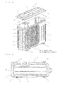
Fig. 2 is a perspective view illustrating a state in which a top panel inFig. 1 is removed; -
Fig. 3 is a perspective view when viewed from the obliquely opposite side fromFig. 2 ; -
Fig. 4 is a top view ofFig. 1 ; -
Fig. 5 is a front view ofFig. 2 ; -
Fig. 6A is a cross-sectional view taken along the line X-X inFig. 5 ; -
Fig. 6B is an enlarged view of a portion A inFig. 6A ; and -
Fig. 7 is a perspective view illustrating a state in which the top panel of the air-conditioning apparatus according toEmbodiment 2 of the invention is removed. -
Fig. 1 is an external perspective view of an outdoor unit of an air-conditioning apparatus according toEmbodiment 1 of the invention,Fig. 2 is a perspective view illustrating a state in which a top panel inFig. 1 is removed,Fig. 3 is a perspective view when viewed from an obliquely opposite side ofFig. 2 , andFig. 4 is a top view ofFig. 1 . In the description given below, the near side of the drawing is referred to as the front side, the far side of the drawing is referred to as the back side, the left side of the drawing is referred to as a left side surface and a right side of the drawing is referred to as the right side surface. - In
Fig. 1 to Fig. 4 ,reference numeral 1 designates a casing of the outdoor unit formed to have a parallelepiped shape opened on top by a bottomplate having legs 2a on a lower surface thereof, a substantially L-shaped front panel 3 mounted from the front side to the left side surface, aside panel 4 mounted from the right side surface to part of the back side, and a substantially L-shaped heat exchanger 5 mounted from the back side through the left side surface to the inside of thefront panel 3. An opening on the top is closed with atop panel 15. Although a partitioning panel, a compressor, refrigerant piping, and electric components are mounted in thecasing 1, these components are not illustrated. -
Reference numeral 30 designates a propeller fan whose driving motor (not illustrated) is attached to amotor mounting panel 6 extending upright from thebottom plate 2 in thecasing 1, abell mouth 7 is provided at an outlet opening of thepropeller fan 30 provided on thefront panel 3, and anoutlet grill 8 is attached to the outside of the outlet opening so as to cover the outlet opening.
Formed on upper end portions of thefront panel 3 and theside panel 4 is anengaging portion 9 slightly reduced in thickness via a shoulder 9a, andscrew holes 10 are provided on theengaging portion 9 corresponding toscrew insertion holes 19 formed on afitting portion 18 of thetop panel 15, described later. - The
top panel 15 is formed to have a size substantially the same as the outline of thecasing 1, and is provided with thefitting portion 18 configured to be fitted to theengaging portion 9 of thecasing 1 along the peripheral edge thereof except for anappentice 16 described below, a portion on the front side corresponding to theoutlet grill 8 is provided with an appentice 16 overhung outward (to the front) from an edge portion. Although the amount of protrusion of theappentice 16 is described to be on the order of 10 to 20 mm from an edge portion in the embodiment, the invention is not limited thereto. Then, thefitting portion 18 is formed with a plurality of thescrew insertion holes 19 including a portion near theappentice 16. - The
appentice 16 is bent or curled inward into a substantially U-shape at a lower portion at a front end portion as shown inFigs. 6A and 6B , which are cross-sectional views taken along the line X-X inFig. 5 (hereinafter, this part is referred to as a bent portion 17).
Also, as shown inFig. 3 and Fig. 4 , an edge portion on the left side surface of thetop panel 15 continuing from theappentice 16 is overhung slightly (for example, on the order of several mm to 10 mm) from the surface of theappentice 16 on the left end portion thereof via ashoulder 21 to form anoverhung portion 20. Aside surface portion 3a of thefront panel 3 of thecasing 1 also has a shape corresponding to theoverhung portion 20 of thetop panel 15 via ashoulder 11. - The
top panel 15 configured in this manner is fitted at thefitting portion 18 thereof to theengaging portion 9 of thecasing 1 and closes the opening on the top of thecasing 1, then is fixed integrally therewith by screwing screws inserted into the plurality ofscrew insertion holes 19 formed on thefitting portion 18 of thetop panel 15 respectively into thescrew holes 10 formed on theengaging portion 9 of thecasing 1 corresponding to thescrew insertion holes 19. At this time, theappentice 16 provided on thetop panel 15 above theoutlet grill 8 projects from the surface of thefront panel 3 to the front surface side until a position in the vicinity of a front edge portion of theoutlet grill 8. - In this case, since the
outlet grill 8 is positioned on the left side of thecasing 1, if the left edge portion and the left end surface of theappentice 16 of thetop pane 15 are flush with each other and this part is formed to be linear, thetop panel 15 may be displaced in the fore-and-aft direction at the time of assembly of the product and hence thescrew insertion holes 19 are not aligned with thescrew holes 10, whereby workability may be deteriorated. - In this embodiment, the left edge portion of the
top panel 15 is formed with theoverhung portion 20 overhung slightly from the left end surface of theappentice 16 via theshoulder 21 provided therebetween and theside surface 3a of thefront panel 3 of thecasing 1 is formed into a shape corresponding to theoverhung portion 20 via theshoulder 11. Therefore, positioning in the fore-and-aft direction of thetop panel 15 at the time of assembly is ensured, so that workability can be improved. - In the outdoor unit according to this embodiment having the configuration as described above, when water droplets adhered on the
top panel 15 or melted snow accumulated on thetop panel 15 flows out toward the front surface, the water droplets flow along thefront panel 3 on the right side in the drawing but, on the side of the outlet grill 8 (the left side), water droplets drop at positions away from the surface of thefront panel 3, come into contact with the lower portion of thefront panel 3 or bridges of theoutlet grill 8, and drop along the bridges because thetop panel 15 is provided with theappentice 16. Therefore, icicles generated by freezing grow on the bridges of theoutlet grill 8 and enter neither thefront panel 3 nor thebell mouth 7. - Therefore, even when the outside air temperature is low and the blown air temperature from the
propeller fan 30 drops to or below freezing, no freezing occurs between thebell mouth 7 and thepropeller fan 30, and generation of abnormal sound of thepropeller fan 30 due to the freezing can be prevented. - Also, since the front end portion of the
appentice 16 of thetop panel 15 is located at a position away (protruded) from thefront panel 3, the user often places his or her finger on theappentice 16. Since thebent portion 17 formed by being bent inward is provided at the lower portion of the distal edge portion of theappentice 16, injury of a finger is prevented and safety can be secured.
Thetop panel 15 is fixed by the screws inserted into the screw insertion holes 19 provided at a plurality of points on thefitting portion 18 including the positions in the vicinity of theappentice 16 screwed into the screw holes 10 formed correspondingly on the engagingportion 9 of thecasing 1. Therefore, even when a force in the direction of lifting theappentice 16 with the hand thereon is applied, deformation of theappentice 16 can be prevented. -
Fig. 7 is a perspective view illustrating a state in which the top panel of the outdoor unit of the air-conditioning apparatus according toEmbodiment 2 of the invention is removed. The identical or same functional portions as inEmbodiment 1 are designated by the same reference numerals.
InEmbodiment 1, the case where theappentice 16 is provided on the edge portion of the portion of thetop panel 15 corresponding to theoutlet grill 8 on the front side has been described. However, in this embodiment, theappentice 16 is provided over the entire edge portion on the front side of thetop panel 15.
In this embodiment as well, the substantially same advantages as inEmbodiment 1 can be obtained. - In this embodiment, the outdoor unit according to
Embodiment
In this embodiment as well, the same advantages as inEmbodiment 1 can be obtained. - 1 casing, 3 front panel, 4 side panel, 5 heat exchanger, 7 bell mouth, 8 outlet grill, 9 engaging portion, 10 screw hole, 11 shoulder, 15 top panel, 16 appentice, 17 bent portion, 18 fitting portion, 19 screw insertion hole, 20 overhung portion, 21 shoulder, 30 propeller fan
Claims (7)
- An outdoor unit comprising:a casing (1) having a substantially parallelepiped shape opened on top;a top panel (15) configured to close an opening on the top of the casing (1);a bell mouth provided at an outlet opening of a propeller fan (30) formed on a front panel (3) which constitutes the casing (1);an outlet grill attached on the front side of the outlet opening; andan apprentice (16) provided at an edge portion of the top panel (15) at a portion corresponding to the outlet grill on the front side of the top panel (15) so as to be overhung to the front from the edge portion.
- The outdoor unit of claim 1, wherein instead of the appentice (16), another appentice (16) is provided over the entire edge portion on the front side of the top panel (15) so as to be overhung to the front from the edge portion.
- The outdoor unit of claim 1 or 2, wherein the appentice (16) is overhung from the edge portion on the front side of the top panel (15) on the order of 10 to 20mm.
- The outdoor unit of any one of claims 1 to 3, wherein the lower portion of the front end portion of the appentice (16) is bent inward to form a bent portion.
- The outdoor unit of any one of claims 1 to 4, wherein the overhung portion overhung on the order of several mm to 10 mm is formed on one of the side edge portions continuing to the appentice (16) of the top panel (15) via a shoulder and the side surface of the casing (1) is formed into a shape corresponding to the overhung portion of the front panel (3).
- The outdoor unit of any one of claims 1 to 5, wherein screw insertion holes (19) are formed at a plurality of positions, which includes positions in the vicinity of the apprentice, in a fitting portion (18) provided on an outer periphery of the top panel (15), and screws inserted into the screw insertion holes (19) are screwed into screw holes (10) provided on an engaging portion (9) on a peripheral edge of an opening on the top of the casing (1), so that the top panel (15) and the casing (1) are integrally fixed.
- An air-conditionning apparatus comprising the outdoor unit of any one of claims 1 to 6.
Applications Claiming Priority (1)
| Application Number | Priority Date | Filing Date | Title |
|---|---|---|---|
| JP2010218481A JP5220076B2 (en) | 2010-09-29 | 2010-09-29 | Outdoor unit and air conditioner equipped with the same |
Publications (3)
| Publication Number | Publication Date |
|---|---|
| EP2436994A2 true EP2436994A2 (en) | 2012-04-04 |
| EP2436994A3 EP2436994A3 (en) | 2012-12-19 |
| EP2436994B1 EP2436994B1 (en) | 2018-01-03 |
Family
ID=44897619
Family Applications (1)
| Application Number | Title | Priority Date | Filing Date |
|---|---|---|---|
| EP11182449.6A Active EP2436994B1 (en) | 2010-09-29 | 2011-09-23 | Outdoor unit and air-conditioning apparatus having the same |
Country Status (3)
| Country | Link |
|---|---|
| EP (1) | EP2436994B1 (en) |
| JP (1) | JP5220076B2 (en) |
| CN (1) | CN102434921B (en) |
Families Citing this family (8)
| Publication number | Priority date | Publication date | Assignee | Title |
|---|---|---|---|---|
| JP5522150B2 (en) * | 2011-11-14 | 2014-06-18 | ダイキン工業株式会社 | Refrigeration equipment outdoor unit |
| JP5642053B2 (en) * | 2011-12-15 | 2014-12-17 | 三菱電機株式会社 | Air conditioner outdoor unit |
| JP6066863B2 (en) * | 2013-08-06 | 2017-01-25 | 三菱電機株式会社 | Outdoor unit and air conditioner |
| JP6223232B2 (en) * | 2014-03-03 | 2017-11-01 | 三菱電機株式会社 | Outdoor unit |
| JP6225953B2 (en) * | 2015-06-26 | 2017-11-08 | ダイキン工業株式会社 | Outdoor unit of heat pump system |
| EP3524894B1 (en) * | 2016-10-07 | 2023-04-19 | Mitsubishi Electric Corporation | Outdoor unit for air conditioning device |
| JP7080337B2 (en) * | 2018-10-23 | 2022-06-03 | 三菱電機株式会社 | Outdoor unit of air conditioner |
| EP4227588A4 (en) * | 2020-10-05 | 2023-11-22 | Mitsubishi Electric Corporation | Outdoor unit for air conditioner |
Citations (1)
| Publication number | Priority date | Publication date | Assignee | Title |
|---|---|---|---|---|
| JP2510078B2 (en) | 1993-05-04 | 1996-06-26 | インターナショナル・ビジネス・マシーンズ・コーポレイション | Control window container, computer system and file window management method |
Family Cites Families (14)
| Publication number | Priority date | Publication date | Assignee | Title |
|---|---|---|---|---|
| JPS5123252Y2 (en) * | 1971-10-25 | 1976-06-15 | ||
| JPS57174963U (en) * | 1981-04-30 | 1982-11-05 | ||
| JP3079928B2 (en) * | 1994-12-22 | 2000-08-21 | ダイキン工業株式会社 | Outdoor unit of air conditioner |
| JP3728043B2 (en) * | 1997-02-13 | 2005-12-21 | 三洋電機株式会社 | Outdoor unit of engine-driven heat pump device |
| JP3478367B2 (en) * | 1997-02-18 | 2003-12-15 | 松下電器産業株式会社 | Outdoor unit for separation type air conditioner |
| JP2000104952A (en) * | 1998-09-25 | 2000-04-11 | Zexel Corp | Outdoor machine for air conditioning |
| JP4667560B2 (en) * | 2000-06-13 | 2011-04-13 | ダイキン工業株式会社 | Snow hood |
| JP4623253B2 (en) * | 2001-03-09 | 2011-02-02 | 株式会社富士通ゼネラル | Split air conditioner outdoor unit |
| JP4091332B2 (en) * | 2002-04-09 | 2008-05-28 | 株式会社伊勢藤 | Air conditioner outdoor unit cover |
| JP2006029756A (en) * | 2004-07-11 | 2006-02-02 | Takayuki Takeuchi | Heat insulating mat and heat shielding method for air conditioner outdoor unit |
| JP4518963B2 (en) * | 2005-01-14 | 2010-08-04 | 中国電力株式会社 | Snow damage prevention device for cooling fan |
| JP4555712B2 (en) * | 2005-03-15 | 2010-10-06 | 東芝キヤリア株式会社 | Air conditioner outdoor unit |
| DE202005016955U1 (en) * | 2005-10-27 | 2007-03-08 | Glen Dimplex Deutschland Gmbh | Heat pump for heating or cooling of building, has heat exchanger and lining encasing outer housing whereby lining is provided with second air inlet and second air outlet |
| DE102009011370B4 (en) * | 2009-03-05 | 2018-03-01 | Stiebel Eltron Gmbh & Co. Kg | Air / water heat pump with a housing arranged in a heat exchanger |
-
2010
- 2010-09-29 JP JP2010218481A patent/JP5220076B2/en active Active
-
2011
- 2011-09-23 EP EP11182449.6A patent/EP2436994B1/en active Active
- 2011-09-28 CN CN201110295548.XA patent/CN102434921B/en active Active
Patent Citations (1)
| Publication number | Priority date | Publication date | Assignee | Title |
|---|---|---|---|---|
| JP2510078B2 (en) | 1993-05-04 | 1996-06-26 | インターナショナル・ビジネス・マシーンズ・コーポレイション | Control window container, computer system and file window management method |
Also Published As
| Publication number | Publication date |
|---|---|
| JP5220076B2 (en) | 2013-06-26 |
| CN102434921A (en) | 2012-05-02 |
| CN102434921B (en) | 2014-09-10 |
| JP2012072973A (en) | 2012-04-12 |
| EP2436994B1 (en) | 2018-01-03 |
| EP2436994A3 (en) | 2012-12-19 |
Similar Documents
| Publication | Publication Date | Title |
|---|---|---|
| EP2436994B1 (en) | Outdoor unit and air-conditioning apparatus having the same | |
| JP5289200B2 (en) | Air conditioner outdoor unit | |
| EP1050720B1 (en) | Air conditioner | |
| WO2010047067A1 (en) | Heat exchange device and heat generating element containing device using same | |
| EP2916081B1 (en) | Outdoor unit | |
| JP2008070048A (en) | Shutter device | |
| EP3076095A1 (en) | Indoor unit | |
| JP4888435B2 (en) | Air conditioner | |
| JP5401355B2 (en) | Air conditioner indoor unit | |
| JPWO2020084681A1 (en) | Outdoor unit of air conditioner | |
| CN204786803U (en) | Air conditioner | |
| JP3843424B2 (en) | Air conditioner indoor unit | |
| EP3614064B1 (en) | Indoor unit for air conditioner | |
| JPH11237083A (en) | Air conditioning equipment | |
| CN209877138U (en) | Air guide component and cabinet air conditioner indoor unit with same | |
| EP2565546A1 (en) | Outdoor unit and bell mouth of air conditioner | |
| WO2016121547A1 (en) | Indoor air conditioning device | |
| JP2017129287A (en) | Outdoor machine of air conditioner and air blower | |
| WO2013153976A1 (en) | Air conditioner | |
| JP4594920B2 (en) | Air conditioner | |
| CN203010861U (en) | Outdoor unit of refrigerating device | |
| JP5109925B2 (en) | Heat exchange device and heating element storage device using the same | |
| EP2312245A2 (en) | Domestic electrical appliance | |
| JP2007205676A (en) | Indoor unit of air conditioner | |
| JP5768208B2 (en) | Ventilation fan |
Legal Events
| Date | Code | Title | Description |
|---|---|---|---|
| PUAI | Public reference made under article 153(3) epc to a published international application that has entered the european phase |
Free format text: ORIGINAL CODE: 0009012 |
|
| AK | Designated contracting states |
Kind code of ref document: A2 Designated state(s): AL AT BE BG CH CY CZ DE DK EE ES FI FR GB GR HR HU IE IS IT LI LT LU LV MC MK MT NL NO PL PT RO RS SE SI SK SM TR |
|
| AX | Request for extension of the european patent |
Extension state: BA ME |
|
| REG | Reference to a national code |
Ref country code: DE Ref legal event code: R079 Ref document number: 602011044677 Country of ref document: DE Free format text: PREVIOUS MAIN CLASS: F24F0001000000 Ipc: F24F0001060000 |
|
| PUAL | Search report despatched |
Free format text: ORIGINAL CODE: 0009013 |
|
| AK | Designated contracting states |
Kind code of ref document: A3 Designated state(s): AL AT BE BG CH CY CZ DE DK EE ES FI FR GB GR HR HU IE IS IT LI LT LU LV MC MK MT NL NO PL PT RO RS SE SI SK SM TR |
|
| AX | Request for extension of the european patent |
Extension state: BA ME |
|
| RIC1 | Information provided on ipc code assigned before grant |
Ipc: F24F 13/20 20060101ALI20121109BHEP Ipc: F24F 1/58 20110101ALI20121109BHEP Ipc: F24F 1/06 20110101AFI20121109BHEP |
|
| 17P | Request for examination filed |
Effective date: 20130612 |
|
| RBV | Designated contracting states (corrected) |
Designated state(s): AL AT BE BG CH CY CZ DE DK EE ES FI FR GB GR HR HU IE IS IT LI LT LU LV MC MK MT NL NO PL PT RO RS SE SI SK SM TR |
|
| STAA | Information on the status of an ep patent application or granted ep patent |
Free format text: STATUS: EXAMINATION IS IN PROGRESS |
|
| 17Q | First examination report despatched |
Effective date: 20170123 |
|
| GRAP | Despatch of communication of intention to grant a patent |
Free format text: ORIGINAL CODE: EPIDOSNIGR1 |
|
| STAA | Information on the status of an ep patent application or granted ep patent |
Free format text: STATUS: GRANT OF PATENT IS INTENDED |
|
| INTG | Intention to grant announced |
Effective date: 20170803 |
|
| GRAS | Grant fee paid |
Free format text: ORIGINAL CODE: EPIDOSNIGR3 |
|
| GRAA | (expected) grant |
Free format text: ORIGINAL CODE: 0009210 |
|
| STAA | Information on the status of an ep patent application or granted ep patent |
Free format text: STATUS: THE PATENT HAS BEEN GRANTED |
|
| AK | Designated contracting states |
Kind code of ref document: B1 Designated state(s): AL AT BE BG CH CY CZ DE DK EE ES FI FR GB GR HR HU IE IS IT LI LT LU LV MC MK MT NL NO PL PT RO RS SE SI SK SM TR |
|
| REG | Reference to a national code |
Ref country code: GB Ref legal event code: FG4D |
|
| REG | Reference to a national code |
Ref country code: CH Ref legal event code: EP Ref country code: AT Ref legal event code: REF Ref document number: 960650 Country of ref document: AT Kind code of ref document: T Effective date: 20180115 |
|
| REG | Reference to a national code |
Ref country code: IE Ref legal event code: FG4D |
|
| REG | Reference to a national code |
Ref country code: SE Ref legal event code: TRGR |
|
| REG | Reference to a national code |
Ref country code: DE Ref legal event code: R096 Ref document number: 602011044677 Country of ref document: DE |
|
| REG | Reference to a national code |
Ref country code: NL Ref legal event code: MP Effective date: 20180103 |
|
| REG | Reference to a national code |
Ref country code: LT Ref legal event code: MG4D |
|
| REG | Reference to a national code |
Ref country code: AT Ref legal event code: MK05 Ref document number: 960650 Country of ref document: AT Kind code of ref document: T Effective date: 20180103 |
|
| PG25 | Lapsed in a contracting state [announced via postgrant information from national office to epo] |
Ref country code: NL Free format text: LAPSE BECAUSE OF FAILURE TO SUBMIT A TRANSLATION OF THE DESCRIPTION OR TO PAY THE FEE WITHIN THE PRESCRIBED TIME-LIMIT Effective date: 20180103 |
|
| PG25 | Lapsed in a contracting state [announced via postgrant information from national office to epo] |
Ref country code: ES Free format text: LAPSE BECAUSE OF FAILURE TO SUBMIT A TRANSLATION OF THE DESCRIPTION OR TO PAY THE FEE WITHIN THE PRESCRIBED TIME-LIMIT Effective date: 20180103 Ref country code: LT Free format text: LAPSE BECAUSE OF FAILURE TO SUBMIT A TRANSLATION OF THE DESCRIPTION OR TO PAY THE FEE WITHIN THE PRESCRIBED TIME-LIMIT Effective date: 20180103 Ref country code: CY Free format text: LAPSE BECAUSE OF FAILURE TO SUBMIT A TRANSLATION OF THE DESCRIPTION OR TO PAY THE FEE WITHIN THE PRESCRIBED TIME-LIMIT Effective date: 20180103 Ref country code: HR Free format text: LAPSE BECAUSE OF FAILURE TO SUBMIT A TRANSLATION OF THE DESCRIPTION OR TO PAY THE FEE WITHIN THE PRESCRIBED TIME-LIMIT Effective date: 20180103 Ref country code: FI Free format text: LAPSE BECAUSE OF FAILURE TO SUBMIT A TRANSLATION OF THE DESCRIPTION OR TO PAY THE FEE WITHIN THE PRESCRIBED TIME-LIMIT Effective date: 20180103 Ref country code: NO Free format text: LAPSE BECAUSE OF FAILURE TO SUBMIT A TRANSLATION OF THE DESCRIPTION OR TO PAY THE FEE WITHIN THE PRESCRIBED TIME-LIMIT Effective date: 20180403 |
|
| PG25 | Lapsed in a contracting state [announced via postgrant information from national office to epo] |
Ref country code: IS Free format text: LAPSE BECAUSE OF FAILURE TO SUBMIT A TRANSLATION OF THE DESCRIPTION OR TO PAY THE FEE WITHIN THE PRESCRIBED TIME-LIMIT Effective date: 20180503 Ref country code: BG Free format text: LAPSE BECAUSE OF FAILURE TO SUBMIT A TRANSLATION OF THE DESCRIPTION OR TO PAY THE FEE WITHIN THE PRESCRIBED TIME-LIMIT Effective date: 20180403 Ref country code: AT Free format text: LAPSE BECAUSE OF FAILURE TO SUBMIT A TRANSLATION OF THE DESCRIPTION OR TO PAY THE FEE WITHIN THE PRESCRIBED TIME-LIMIT Effective date: 20180103 Ref country code: LV Free format text: LAPSE BECAUSE OF FAILURE TO SUBMIT A TRANSLATION OF THE DESCRIPTION OR TO PAY THE FEE WITHIN THE PRESCRIBED TIME-LIMIT Effective date: 20180103 Ref country code: RS Free format text: LAPSE BECAUSE OF FAILURE TO SUBMIT A TRANSLATION OF THE DESCRIPTION OR TO PAY THE FEE WITHIN THE PRESCRIBED TIME-LIMIT Effective date: 20180103 Ref country code: PL Free format text: LAPSE BECAUSE OF FAILURE TO SUBMIT A TRANSLATION OF THE DESCRIPTION OR TO PAY THE FEE WITHIN THE PRESCRIBED TIME-LIMIT Effective date: 20180103 Ref country code: GR Free format text: LAPSE BECAUSE OF FAILURE TO SUBMIT A TRANSLATION OF THE DESCRIPTION OR TO PAY THE FEE WITHIN THE PRESCRIBED TIME-LIMIT Effective date: 20180404 |
|
| REG | Reference to a national code |
Ref country code: DE Ref legal event code: R097 Ref document number: 602011044677 Country of ref document: DE |
|
| PG25 | Lapsed in a contracting state [announced via postgrant information from national office to epo] |
Ref country code: EE Free format text: LAPSE BECAUSE OF FAILURE TO SUBMIT A TRANSLATION OF THE DESCRIPTION OR TO PAY THE FEE WITHIN THE PRESCRIBED TIME-LIMIT Effective date: 20180103 Ref country code: RO Free format text: LAPSE BECAUSE OF FAILURE TO SUBMIT A TRANSLATION OF THE DESCRIPTION OR TO PAY THE FEE WITHIN THE PRESCRIBED TIME-LIMIT Effective date: 20180103 Ref country code: AL Free format text: LAPSE BECAUSE OF FAILURE TO SUBMIT A TRANSLATION OF THE DESCRIPTION OR TO PAY THE FEE WITHIN THE PRESCRIBED TIME-LIMIT Effective date: 20180103 Ref country code: IT Free format text: LAPSE BECAUSE OF FAILURE TO SUBMIT A TRANSLATION OF THE DESCRIPTION OR TO PAY THE FEE WITHIN THE PRESCRIBED TIME-LIMIT Effective date: 20180103 |
|
| PLBE | No opposition filed within time limit |
Free format text: ORIGINAL CODE: 0009261 |
|
| STAA | Information on the status of an ep patent application or granted ep patent |
Free format text: STATUS: NO OPPOSITION FILED WITHIN TIME LIMIT |
|
| PG25 | Lapsed in a contracting state [announced via postgrant information from national office to epo] |
Ref country code: SM Free format text: LAPSE BECAUSE OF FAILURE TO SUBMIT A TRANSLATION OF THE DESCRIPTION OR TO PAY THE FEE WITHIN THE PRESCRIBED TIME-LIMIT Effective date: 20180103 Ref country code: DK Free format text: LAPSE BECAUSE OF FAILURE TO SUBMIT A TRANSLATION OF THE DESCRIPTION OR TO PAY THE FEE WITHIN THE PRESCRIBED TIME-LIMIT Effective date: 20180103 Ref country code: SK Free format text: LAPSE BECAUSE OF FAILURE TO SUBMIT A TRANSLATION OF THE DESCRIPTION OR TO PAY THE FEE WITHIN THE PRESCRIBED TIME-LIMIT Effective date: 20180103 Ref country code: CZ Free format text: LAPSE BECAUSE OF FAILURE TO SUBMIT A TRANSLATION OF THE DESCRIPTION OR TO PAY THE FEE WITHIN THE PRESCRIBED TIME-LIMIT Effective date: 20180103 |
|
| 26N | No opposition filed |
Effective date: 20181005 |
|
| PG25 | Lapsed in a contracting state [announced via postgrant information from national office to epo] |
Ref country code: SI Free format text: LAPSE BECAUSE OF FAILURE TO SUBMIT A TRANSLATION OF THE DESCRIPTION OR TO PAY THE FEE WITHIN THE PRESCRIBED TIME-LIMIT Effective date: 20180103 |
|
| PG25 | Lapsed in a contracting state [announced via postgrant information from national office to epo] |
Ref country code: MC Free format text: LAPSE BECAUSE OF FAILURE TO SUBMIT A TRANSLATION OF THE DESCRIPTION OR TO PAY THE FEE WITHIN THE PRESCRIBED TIME-LIMIT Effective date: 20180103 |
|
| REG | Reference to a national code |
Ref country code: CH Ref legal event code: PL |
|
| GBPC | Gb: european patent ceased through non-payment of renewal fee |
Effective date: 20180923 |
|
| REG | Reference to a national code |
Ref country code: BE Ref legal event code: MM Effective date: 20180930 |
|
| REG | Reference to a national code |
Ref country code: IE Ref legal event code: MM4A |
|
| PG25 | Lapsed in a contracting state [announced via postgrant information from national office to epo] |
Ref country code: LU Free format text: LAPSE BECAUSE OF NON-PAYMENT OF DUE FEES Effective date: 20180923 |
|
| PG25 | Lapsed in a contracting state [announced via postgrant information from national office to epo] |
Ref country code: IE Free format text: LAPSE BECAUSE OF NON-PAYMENT OF DUE FEES Effective date: 20180923 |
|
| PG25 | Lapsed in a contracting state [announced via postgrant information from national office to epo] |
Ref country code: LI Free format text: LAPSE BECAUSE OF NON-PAYMENT OF DUE FEES Effective date: 20180930 Ref country code: CH Free format text: LAPSE BECAUSE OF NON-PAYMENT OF DUE FEES Effective date: 20180930 Ref country code: FR Free format text: LAPSE BECAUSE OF NON-PAYMENT OF DUE FEES Effective date: 20180930 Ref country code: BE Free format text: LAPSE BECAUSE OF NON-PAYMENT OF DUE FEES Effective date: 20180930 |
|
| PG25 | Lapsed in a contracting state [announced via postgrant information from national office to epo] |
Ref country code: GB Free format text: LAPSE BECAUSE OF NON-PAYMENT OF DUE FEES Effective date: 20180923 |
|
| PG25 | Lapsed in a contracting state [announced via postgrant information from national office to epo] |
Ref country code: MT Free format text: LAPSE BECAUSE OF NON-PAYMENT OF DUE FEES Effective date: 20180923 |
|
| PG25 | Lapsed in a contracting state [announced via postgrant information from national office to epo] |
Ref country code: TR Free format text: LAPSE BECAUSE OF FAILURE TO SUBMIT A TRANSLATION OF THE DESCRIPTION OR TO PAY THE FEE WITHIN THE PRESCRIBED TIME-LIMIT Effective date: 20180103 |
|
| PG25 | Lapsed in a contracting state [announced via postgrant information from national office to epo] |
Ref country code: PT Free format text: LAPSE BECAUSE OF FAILURE TO SUBMIT A TRANSLATION OF THE DESCRIPTION OR TO PAY THE FEE WITHIN THE PRESCRIBED TIME-LIMIT Effective date: 20180103 Ref country code: HU Free format text: LAPSE BECAUSE OF FAILURE TO SUBMIT A TRANSLATION OF THE DESCRIPTION OR TO PAY THE FEE WITHIN THE PRESCRIBED TIME-LIMIT; INVALID AB INITIO Effective date: 20110923 |
|
| PG25 | Lapsed in a contracting state [announced via postgrant information from national office to epo] |
Ref country code: MK Free format text: LAPSE BECAUSE OF NON-PAYMENT OF DUE FEES Effective date: 20180103 |
|
| REG | Reference to a national code |
Ref country code: DE Ref legal event code: R084 Ref document number: 602011044677 Country of ref document: DE |
|
| P01 | Opt-out of the competence of the unified patent court (upc) registered |
Effective date: 20230512 |
|
| PGFP | Annual fee paid to national office [announced via postgrant information from national office to epo] |
Ref country code: SE Payment date: 20230810 Year of fee payment: 13 Ref country code: DE Payment date: 20230802 Year of fee payment: 13 |