EP2436861A2 - Locking mechanism, locking bolt, actuator and method of assembly - Google Patents
Locking mechanism, locking bolt, actuator and method of assembly Download PDFInfo
- Publication number
- EP2436861A2 EP2436861A2 EP11183834A EP11183834A EP2436861A2 EP 2436861 A2 EP2436861 A2 EP 2436861A2 EP 11183834 A EP11183834 A EP 11183834A EP 11183834 A EP11183834 A EP 11183834A EP 2436861 A2 EP2436861 A2 EP 2436861A2
- Authority
- EP
- European Patent Office
- Prior art keywords
- actuator
- support plate
- locking
- section
- key
- Prior art date
- Legal status (The legal status is an assumption and is not a legal conclusion. Google has not performed a legal analysis and makes no representation as to the accuracy of the status listed.)
- Granted
Links
Images


Classifications
-
- E—FIXED CONSTRUCTIONS
- E05—LOCKS; KEYS; WINDOW OR DOOR FITTINGS; SAFES
- E05B—LOCKS; ACCESSORIES THEREFOR; HANDCUFFS
- E05B67/00—Padlocks; Details thereof
- E05B67/36—Padlocks with closing means other than shackles ; Removable locks, the lock body itself being the locking element; Padlocks consisting of two separable halves or cooperating with a stud
-
- B—PERFORMING OPERATIONS; TRANSPORTING
- B60—VEHICLES IN GENERAL
- B60D—VEHICLE CONNECTIONS
- B60D1/00—Traction couplings; Hitches; Draw-gear; Towing devices
- B60D1/58—Auxiliary devices
- B60D1/60—Covers, caps or guards, e.g. comprising anti-theft devices
Definitions
- the key-operated lock is a "disc-detainer" type, with the lock mechanism comprising a number of discs all of which have a peripheral slot.
- the discs are rotated by the key, with the coded section of the key rotating the respective discs through a predetermined angle.
- the coded section in cooperation with the form of each disc, results in the peripheral slots all being aligned in the unlocked condition, and when aligned a locking bar of the lock mechanism enters the respective slots and permits the lock mechanism to be rotated within its housing.
- Disc detainer locks are known to be very secure and are therefore suitable for the particular applications in which a locking mechanism will be used.
- the key-operated lock and actuator 24 are retained in the first part 10 by a snap ring (not shown) which locates in a retaining groove 40.
- the cross-section of the snap ring is substantially circular, and the retaining groove 40 is substantially semi-circular with a substantially identical radius to the snap ring. The snap ring is therefore a close fit in the retaining groove 40.
Landscapes
- Engineering & Computer Science (AREA)
- Transportation (AREA)
- Mechanical Engineering (AREA)
- Snaps, Bayonet Connections, Set Pins, And Snap Rings (AREA)
- Connection Of Plates (AREA)
Abstract

Description
- This invention relates to a locking mechanism, to a locking bolt, to an actuator for use in the locking mechanism and locking bolt, and to a method of assembly.
- The locking mechanism has been designed primarily for use as part of a locking bolt and the following description will therefore relate mainly to such applications. The use of the locking mechanism in other applications is not thereby excluded.
- Locking bolts (which are sometimes referred to as locking pins) are used to secure certain articles, one article for which a locking bolt is suitable being a trailer hitch lock. In such an application, the hitch lock has an open bottom and is lowered around the hitch of the trailer in known fashion. The side walls of the hitch lock have a pair of aligned openings which can receive the locking bolt, the locking bolt passing underneath the hitch and bridging the gap between the aligned openings. When the locking bolt is fitted, the hitch lock and locking bolt together surround a part of the hitch, with the fitted locking bolt preventing the hitch lock from being lifted from the trailer hitch. The locking bolt is designed to be difficult and time-consuming to cut through, even with specialised tools, so that unless the locking bolt is unlocked and removed by use of the correct key, it is substantially immovable and so effectively secures the hitch lock to the trailer hitch.
- A locking bolt is described in
UK patent 2 405 443 - In commercial embodiments of prior art locking bolts made according to
GB 2 405 443 - To restrict the actuator to the desired rotary movement, the cammed section is located between two support plates, the support plates being circular and a close fit within the recess in the first part of the locking bolt.
- To increase the security of the locking bolt of
GB 2 405 443 - Nevertheless, persons intent on disabling the locking bolt are known to pass a drill through the keyhole and to drill into the lock. Even though the keyhole is too small for the lock to pass through it allows a sufficiently large drill to be used to destroy a large proportion of the internal components of the lock and to permit unauthorised unlocking and subsequent disassembly of the locking bolt.
- The present invention seeks to avoid or reduce the likelihood that the lock can be damaged by a drill. The invention also seeks to provide an improved actuator and method of assembly, and also to reduce or avoid other disadvantages of the known locking mechanisms and locking bolts as set out below.
- According to the first aspect of the invention there is provided a locking mechanism comprising a first part and a second part, the first part and second part being securable together by way of at least one locking member carried by the first part, the locking member being driven into its locking position by an actuator which is in turn driven by a key-operated lock carried by the first part, the first part having a first end portion, the first part having a second end opposed to its first end portion, the first part having a recess in its second end which is adapted to accommodate the key-operated lock and the actuator, the actuator having a cam section whereby rotation of the actuator causes radial movement of the locking member, the actuator having a first support plate located between the key-operated lock and the cam section and a second support plate located to the opposed side of the cam section, the support plates being adapted for sliding engagement with the substantially circular internal surface of the recess whereby the actuator is restricted to substantially rotary movement, the first support plate having an acircular periphery whereby the first support plate can pass the locking member(s) during assembly of the first part.
- In practical embodiments, the locking mechanism may be adapted to secure parts of a wheel clamp for example, such as the wheel clamp of our co-pending European patent application
11173072.7 - In other embodiments the locking mechanism is part of a locking bolt. In a locking bolt the second part has a second end portion and there is a central section between the first and second end portions, the first and second end portions being of larger cross-sectional dimension than the central section.
- Prior art actuators for locking mechanisms, and in particular locking bolts, have support plates which cannot pass the locking member(s) during assembly of the first part. Such actuators must therefore be assembled from separate elements within the recess, with the first support plate being inserted into the recess before the locking member(s) and the second support plate being inserted after the locking member(s). The cam section is typically inserted with the second support plate. On the other hand, the actuator of the present invention can be inserted after the locking member(s) and it can therefore be made as a one-piece construction, preferably a casting. The present actuator therefore avoids the joints and connections of the prior art actuators, which joints and connections provide the weakest points of the actuator and can permit the unauthorised disassembly of the locking bolt if sufficient loading is applied to the lock.
- Desirably, the locking member(s) have a flattened base which lies against the cam section in use. The flattened base facilitates assembly of the first part, the acircular periphery of the first support plate preferably including a flat which can be aligned with the flattened base of the locking member(s) during assembly.
- According to the second aspect of the invention there is provided a locking mechanism comprising a first part and a second part, the first part and second part being securable together by way of a key-operated lock carried by the first part, the first part having a first end portion, the first part having a second end opposed to its first end portion, the first part having an opening in its second end through which the key-operated lock is inserted and a keyhole in its first end portion, the keyhole being substantially oblong in shape with a major axis and a minor axis, the maximum dimension of the minor axis being less than 5mm.
- It will be understood that the key must be rotated through around 90° within the keyhole in order to actuate the lock, and for this reason the keyholes in prior art locking mechanisms, particularly those used for locking bolts, have been made circular. With a typical key for a locking bolt having a maximum cross-sectional dimension (along its major axis) of 7mm or more, this requires the keyhole to be at least 7mm in diameter. A 7mm drill can therefore be inserted through the keyhole, which drill can cause sufficient damage to the lock to permit unauthorised disassembly of the locking bolt.
- The inventors have, however, realised that the keyhole can be made acircular, and the key shaft can be shaped accordingly, so as to reduce the size of a drill (or other tool) which can be inserted through the keyhole.
- Preferably, the maximum dimension of the minor axis of the keyhole is less than 4mm, ideally approximately 3mm.
- Desirably, the key has a coded section adapted to engage the lock mechanism in use, a handle part for manual gripping during use, and a shaft between the coded section and handle part, the shaft having a smaller cross-sectional dimension than the coded section.
- Ideally, the key-operated lock is a "disc-detainer" type, with the lock mechanism comprising a number of discs all of which have a peripheral slot. The discs are rotated by the key, with the coded section of the key rotating the respective discs through a predetermined angle. The coded section, in cooperation with the form of each disc, results in the peripheral slots all being aligned in the unlocked condition, and when aligned a locking bar of the lock mechanism enters the respective slots and permits the lock mechanism to be rotated within its housing. Disc detainer locks are known to be very secure and are therefore suitable for the particular applications in which a locking mechanism will be used.
- Notwithstanding that the keyhole according to the second aspect of the invention is substantially oblong in shape, the other aspects of the invention can utilise keyholes of other shapes, such as a cross or a star shape. It will be understood that most of the benefits of an oblong keyhole can be shared by these other shapes, in that they also provide a smaller opening thus making a drill attack more difficult and yet still permit the rotation of a key with a shaft having an appropriate cross-sectional dimension.
- Preferably, the key-operated lock and the actuator are secured in the first part by a snap ring having a substantially circular cross-section.
- In prior art locking mechanisms of this type, the key-operated lock and actuator are secured within the first part by a circlip. A circlip has an oblong cross-section and is located in an oblong-shaped groove in the first part. It is recognised that a significant force is necessary to remove the key-operated lock and actuator from the first part of the locking mechanism, but such forces are often available to persons intent on disabling the lock, and the required force can often be imparted to the lock (by way of the keyhole) so as to push the circlip out of its retaining groove and disable the locking mechanism. With the present invention only a smaller forcing tool can be passed through the keyhole, and a substantially circular cross-section snap ring will result in forces which seek to push the lock out of the first part acting to press the snap ring further into its retaining groove. A lock which is secured by a snap ring therefore requires significantly more force to remove it forcibly from the first part, and in particular requires considerably more force than can typically be applied to the lock of a locking mechanism.
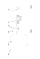
- The invention will now be described in more detail, by way of example, with reference to the accompanying drawings, in which:
- Fig.1
- shows a side sectional view of the first part of a locking mechanism according to the invention, and part of the second part;
- Fig.2
- shows an end view of the first part;
- Fig.3
- shows a side view of the actuator;
- Fig.4
- shows an end view of the actuator;
- Fig.5
- shows a sectional view of the locking members and a preferred design of actuator;
- Fig.6
- shows a side view of the key of the key-operated lock;
- Fig.7
- shows an end view of the key; and
- Fig.8
- shows a cross-section through one of the support plates of the actuator during assembly of the first part.
- The locking mechanism of the present invention comprises a
first part 10 and asecond part 12, and acts to secure thefirst part 10 to thesecond part 12 as explained below. Only part of thesecond part 12 is shown inFig.1 as the form of the remainder of the second part is not relevant to the structure and method of assembly of the lock mechanism. - In one practical embodiment the lock mechanism is part of a locking bolt, in which case (in common with prior art locking bolts of this type, and in common with the locking bolt of
GB 2 405 443 second part 12 comprises an elongatecentral section 14 and an enlarged end (not shown) which has a cross-sectional dimension greater than the central section, and preferably (but not necessarily) of identical size and shape to the enlargedfirst end portion 16 of thefirst part 10. Accordingly, whilst in other embodiments of locking bolt the first part can include the central section, in the preferred embodiment shown the first part is separable from the central section. - Also in common with locking mechanisms for locking bolts such as that of
GB 2 405 443 second part 12 has arecess 20 with an undercutannular groove 22. Thefirst part 10 has arecess 18 which accommodates a key-operated lock (not shown), an actuator 24 (seeFigs. 3-5 ), and two locking members 26 (SeeFigs. 5 and8 ). The lockingmembers 26 can project fromholes 30 formed through the wall surrounding therecess 18 in the first part 10 (only one of which holes can be seen inFig.1 ) and into the undercutannular groove 22, whereby to secure thefirst part 10 to thesecond part 12. - The key-operated lock and
actuator 24 are located in the first part by way of its opensecond end 32. Thus, the key-operated lock is not inserted into the first part through an opening in thefirst end portion 16, and thekeyhole 34 in thefirst end portion 16 can therefore be made smaller than the key-operated lock, and in particular only just large enough to accommodate the key 60 (Figs. 6,7 ). This prevents the key-operated lock being forcibly removed through thekeyhole 34. - As seen in
Fig.2 , thekeyhole 34 is substantially oblong in shape, with rounded ends. Specifically, the keyhole has a major axis of dimension M and a minor axis of dimension m, the major axis being larger than the minor axis. It will be understood that the maximum diameter drill which can be passed through thekeyhole 34 corresponds to the minor axis m, and reducing the dimension of the minor axis reduces the diameter of drill which can be used, and therefore also reduces the damage which can be inflicted upon the components within the lock. In the present invention, the dimension of the minor axis m can be as small as approximately 3mm, and it is known that a 3mm drill will be unlikely to disable a disc detainer lock for example. - In tests conducted prior to filing the present application, attempts were made to enlarge the
keyhole 34 by using a drill bit having a larger diameter than the minor axis m. Those tests were undertaken with a hand drill fitted with a conventional fluted twist drill, as typically used for the unauthorised drilling out of locks of prior art locking mechanisms. It was found that the drill bit wanders uncontrollably along thekeyhole 34 and breaks before significant material of thefirst part 10 is removed. In practice, a person intent on disassembling a locking mechanism (perhaps to steal a caravan which is secured thereby) will not likely carry replacement drill bits, and will therefore be unlikely to continue to attack the locking mechanism once the drill bit has broken or become damaged. - The key-operated lock and
actuator 24 are retained in thefirst part 10 by a snap ring (not shown) which locates in a retaininggroove 40. The cross-section of the snap ring is substantially circular, and the retaininggroove 40 is substantially semi-circular with a substantially identical radius to the snap ring. The snap ring is therefore a close fit in the retaininggroove 40. - The circular cross-sectional shape of the snap ring means that attempts to forcibly remove the key-operated lock and
actuator 24 from the first part 10 (perhaps by way of a forcing tool inserted through the keyhole 34) will result in the snap ring being pressed more forcibly into the retaininggroove 40, i.e. there is little or no tendency for the snap ring to lift out of the retaininggroove 40 as in the case of a conventional circlip of oblong cross-section. - The
actuator 24, and in particular itscammed section 42, is shown in more detail inFigs. 3-5 . Thecammed section 42 of theactuator 24 is substantially oblong in shape, with (two) rounded ends 44. In accordance with preferred embodiments of the invention the rounded ends 44 have a first more-sharplycurved section 44a which facilitates the transfer of rotational movement of thecammed section 42 into linear movement of the lockingmembers 26. The rounded ends 44 have asecond section 44b which is less sharply curved (substantially flat). Thecurved sections smooth junction 44c. - Whilst the locking
members 26 have a curved top to match the curved form of the undercutannular groove 22, they have a flat bottom 50 in engagement with thecammed section 42 of the actuator 24). The advantage of these structural features is described below in relation toFig.8 . - It will be understood that in the unlocked condition the
flat bottom 50 of each of the lockingmembers 26 engages the respectiveflat sides 52 of thecammed section 42. The key-operated lock is designed to rotate through approximately 90° between its unlocking and locking conditions. In known fashion, the key-operated lock has a projecting blade which locates within thechannel 54 of the actuator, so that the actuator is driven to rotate through approximately 90° also. - Accordingly, in its locked condition the longitudinal axis L-L of the
cammed section 42 of theactuator 24 should be aligned with the axis A-A of the lockingmembers 26. In practice, however, with manufacturing tolerances and age-related wear of the lock componentry, the lock will often rotate thecammed section 42 through less than 90°, a situation which is demonstrated inFig.5 . - It is known for attempts to be made to forcibly separate the
first part 10 of the locking mechanism from thesecond part 12. Considerable leverage may be applied to separate these components, and forces which seek to separate thefirst part 10 from thesecond part 12 will act to drive the lockingmembers 26 out of the undercutannular groove 22, and thereby seek to drive the lockingmembers 26 towards one another from the (locked) position shown inFig.5 . - In preferred arrangements of the present invention, such forces increase the loading of the locking
members 26 upon thecammed section 42, but cause little or no rotational force upon theactuator 24, and therefore do not impart any (significant) force upon the lock. Thus, it is arranged that thejunctions 44c do not lie upon the longitudinal axis L-L of thecammed section 42, so that less than 90° rotation is required for the point of engagement between therounded end 44 and the lockingmember 26 to pass thejunctions 44c. Once thecammed section 42 has rotated sufficiently that the lockingmembers 26 engage the (substantially flat) surfaces 44b the tendency for forces upon the locking members to cause anticlockwise (unlocking) movement of the cammed section 42 (as shown inFig.5 ) is significantly reduced or even eliminated (depending upon the exact form of thesurfaces 44b). Thus, rotating thecammed section 42 beyond thejunctions 44c creates an "over centre" effect, reducing the tendency for thecammed section 42 to be forcibly rotated towards the unlocked position. - The key 60 is shown in
Figs. 6 and 7 and comprises a codedsection 62, ahandle part 64, and ashaft 66 between the codedsection 62 and thehandle part 64. In accordance with a preferred aspect of the present invention, theshaft 66 has aportion 70 with a reduced cross-sectional dimension, and in particular a substantially circular cross-section as shown inFig.7 . The reducedportion 70 lies within thekeyhole 34 when the key 60 is fully engaged with the lock mechanism, and the diameter of the reducedportion 70 is only slightly smaller than the dimension of the minor axis m. The reducedsection 70 thereby permits thekeyhole 34 to be acircular without preventing rotation of the key. - As shown in
Fig.3 , thecammed section 42 of theactuator 24 is located between twosupport plates support plate 74 is substantially circular, and is a close sliding fit within therecess 18, whereby to prevent unwanted lateral movement of the actuator in use, and in particular to restrict thecammed section 42 to the desired rotary movement. As better seen inFig.8 , however, thesupport plate 72 is acircular, and whilst it hasparts 76 which are a close sliding fit within therecess 18 theparts 76 are joined by twoflats 80. It will be understood fromFig.8 that the twoflats 80, and theflat bottoms 50 of the lockingmembers 26, permit thesupport plate 72 to pass the locking members during assembly of thefirst part 10. - It will also be understood that the
flat bottoms 50 of the lockingmembers 26 are larger than theholes 30 so that the lockingmembers 26 are retained in thefirst part 10. Biasing springs can be provided if desired so as to bias the lockingmembers 26 towards (and into sliding engagement with) thecammed section 42. Gaps are shown between the respective parts inFig.8 for clarity, and in particular between therespective parts 76 and the inside surface of therecess 18, but it will be understood that in practice theparts 76 are a close sliding fit within therecess 18 so as to assist thesupport plate 74 in preventing unwanted lateral movement of the actuator in use, and in restricting thecammed section 42 to the desired rotary movement. - It will be understood that in an alternative embodiment the
parts 76 could be extended towards the lockingmembers 26, and theflats 80 could be replaced by recesses which accommodate theflat bottoms 50 of the locking members. - The
first part 10 can therefore be assembled in the following manner: {i} insert the key-operated lock from the opensecond end 32; {ii} insert the lockingmembers 26 into therecess 18 and into theirrespective holes 30; {iii} insert theactuator 24 into therecess 18, with theflats 80 passing theflat bottoms 50 of the locking members; {iv} insert the snap ring into the retaininggroove 40. - It will be understood that each of the separate improvements to the known locking mechanisms which have been described can be used independently of the others, and each will provide greater security against damage or disablement of the locking mechanism. The greatest advantage is obtained by a locking mechanism which utilises all of the improvements as in the described embodiments.
Claims (15)
- A locking mechanism comprising a first part (10) and a second part (12), the first part and second part being securable together by way of at least one locking member (26) carried by the first part, the locking member(s) being driven into its locking position by an actuator (24) which is in turn driven by a key-operated lock carried by the first part, the first part having a first end portion (16), the first part having a second end (32) opposed to its first end portion (16), the first part having a recess (18) in its second end (32) which is adapted to accommodate the key-operated lock and the actuator (24), the actuator having a cammed section (42) whereby rotation of the actuator causes radial movement of the locking member(s) (26), the actuator having a first support plate (72) located between the cammed section (42) and the key-operated lock and a second support plate (74) located to the opposed side of the cammed section (42), the support plates (72, 74) being adapted for sliding engagement with the substantially circular internal surface of the recess (18), characterised in that the first support plate (72) has an acircular periphery (76, 80) whereby the first support plate can pass the locking member(s) (26) during assembly of the first part.
- The locking mechanism according to claim 1 in which the first support plate (72), the cammed section (42) and the second support plate (74) are integrally formed.
- The locking mechanism according to claim 1 or claim 2 in which the cammed section (42) is of generally oblong form with two rounded ends (44), the rounded ends (44) being connected by substantially flat surfaces (52).
- The locking mechanism according to claim 3 in which each of the rounded ends (44) has a first more-sharply curved section (44a) and a second less-sharply-curved section (44b), the curved sections (44a and 44b) meeting at a relatively smooth junction 44c.
- The locking mechanism according to any one of claims 1-4 in which the locking member(s) (26) has a flattened base (50) which engages the cammed section (42) in use.
- The locking mechanism according to any one of claims 1-5 in which the acircular periphery of the first support plate (72) includes a portion (80) adapted to pass the locking member (26) during assembly.
- The locking mechanism according to any one of claims 1-6 in which the first part has a keyhole (34) in its first end portion, the keyhole (34) being substantially oblong in shape with a major axis and a minor axis, the maximum dimension of the minor axis being less than 4mm.
- The locking mechanism according to claim 7 in which the minor axis is approximately 3mm.
- The locking mechanism according to claim 7 or claim 8 in which the ends of the keyhole are rounded.
- The locking mechanism according to any one of claims 7-9 including a key (60) for the key-operated lock, the key (60) having a coded section (62) adapted to engage the lock in use, a handle part (64) for manual gripping during use, and a shaft (66) between the coded section and handle part, the shaft (66) having a smaller cross-sectional dimension than the coded section (62).
- The locking mechanism according to any one of claims 1-10 in which the key-operated lock and the actuator (24) are secured in the first part (10) by a snap ring having a substantially circular cross-section.
- An actuator for the lock mechanism of any one of claims 1-11, the actuator having:a first support plate (72);a second support plate (74);a cammed section (24) located between the first and second supportplates;characterised in that the first support plate (72) has an acircular periphery (76, 80), and in that the first support plate (72), the cammed section (42) and the second support plate (74) are integrally formed.
- A locking bolt having a locking mechanism according to any one of claims 1-11, the second part having a second end portion, the locking bolt having a central section between the first and second end portions, the first and second end portions being of larger cross-sectional dimension than the central section.
- A method of assembling a first part of a locking mechanism, the method including the steps of:{i} providing a first part (10) having a first end portion (16) and a second end (32) opposed to the first end portion, the first end portion having a larger cross-sectional dimension than the second end, the first part having a recess (18) in the second end and a keyhole (34) in its first end portion, the first part having at least one hole (30) through the wall surrounding the recess (18);{ii} inserting a key-operated lock into the first part (10) from the second end (32);{iii} inserting a locking member (26) into the recess (18) and into the hole (30);{iv} providing an actuator (24) having a first support plate (72), a second support plate (74) and a cammed section (42) between the support plates, the first support plate being acircular;{v} inserting the actuator (24) into the recess (18) so that the first support plate (72) passes the locking member (26) and the cam section (42) lies adjacent to the locking member;{vi} fitting a retaining means whereby to retain the actuator (24) and key-operated lock within the recess (18).
- The method according to claim 14 in which the first support plate (72), the cammed section (42) and the second support plate (74) are integrally formed.
Applications Claiming Priority (1)
| Application Number | Priority Date | Filing Date | Title |
|---|---|---|---|
| GBGB1016665.0A GB201016665D0 (en) | 2010-10-04 | 2010-10-04 | Locking bolt |
Publications (3)
| Publication Number | Publication Date |
|---|---|
| EP2436861A2 true EP2436861A2 (en) | 2012-04-04 |
| EP2436861A3 EP2436861A3 (en) | 2017-06-07 |
| EP2436861B1 EP2436861B1 (en) | 2018-05-30 |
Family
ID=43243461
Family Applications (1)
| Application Number | Title | Priority Date | Filing Date |
|---|---|---|---|
| EP11183834.8A Active EP2436861B1 (en) | 2010-10-04 | 2011-10-04 | Locking mechanism, locking bolt, actuator and method of assembly |
Country Status (2)
| Country | Link |
|---|---|
| EP (1) | EP2436861B1 (en) |
| GB (1) | GB201016665D0 (en) |
Citations (1)
| Publication number | Priority date | Publication date | Assignee | Title |
|---|---|---|---|---|
| GB2405443A (en) | 2003-09-01 | 2005-03-02 | Stronghold Security Products L | Locking bolt |
Family Cites Families (3)
| Publication number | Priority date | Publication date | Assignee | Title |
|---|---|---|---|---|
| FR2633022A1 (en) * | 1988-06-15 | 1989-12-22 | Carreras Jacques | Dismantleable pivot, particularly for the articulated mounting of instruments on civil engineering works plant, and stop means for such a pivot |
| FR2689928B1 (en) * | 1992-04-13 | 1994-07-08 | Jacques Carreras | WATERPROOF PADLOCKS. |
| GB0318596D0 (en) * | 2003-08-07 | 2003-09-10 | Pitt Josiah E | Lock device |
-
2010
- 2010-10-04 GB GBGB1016665.0A patent/GB201016665D0/en not_active Ceased
-
2011
- 2011-10-04 EP EP11183834.8A patent/EP2436861B1/en active Active
Patent Citations (1)
| Publication number | Priority date | Publication date | Assignee | Title |
|---|---|---|---|---|
| GB2405443A (en) | 2003-09-01 | 2005-03-02 | Stronghold Security Products L | Locking bolt |
Also Published As
| Publication number | Publication date |
|---|---|
| EP2436861A3 (en) | 2017-06-07 |
| EP2436861B1 (en) | 2018-05-30 |
| GB201016665D0 (en) | 2010-11-17 |
Similar Documents
| Publication | Publication Date | Title |
|---|---|---|
| EP1781876B1 (en) | Re-keyable lock assembly | |
| US6860131B2 (en) | Rekeying a lock assembly | |
| US8347678B2 (en) | Rekeyable lock cylinder assembly | |
| CN102112689B (en) | cylinder protection system | |
| CA2681671A1 (en) | Hierarchical cylinder lock system | |
| WO2006110951A1 (en) | Armoured cable assemblies, locking assemblies, mounting systems and anchors | |
| US12196000B2 (en) | Cylinder lock with multiple, supplemental locking elements and associated key | |
| US7181941B2 (en) | Lock system with improved auxiliary pin tumbler stack | |
| EP2436861B1 (en) | Locking mechanism, locking bolt, actuator and method of assembly | |
| CN111425069B (en) | Lock core structure based on automatic deadlock after damage | |
| EP3159465B1 (en) | Cylinder lock | |
| AU2003272463B2 (en) | Enhanced security catch assembly for retaining a handle on a spindle | |
| TWI693328B (en) | Rekeyable lock cylinder with enhanced torque resistance | |
| KR102481861B1 (en) | lock device | |
| GB2405443A (en) | Locking bolt | |
| EP4115036B1 (en) | Cylinder lock and key thereof | |
| WO1995012046A1 (en) | Lock | |
| HK40086274A (en) | Cylinder lock and key thereof | |
| HK40086274B (en) | Cylinder lock and key thereof | |
| KR200475795Y1 (en) | Screw Lock | |
| JP4599202B2 (en) | Cylinder lock plug manufacturing method, cylinder lock plug, and tumbler receiving hole punching jig for cylinder lock plug | |
| HK1159715B (en) | Cylinder protective system | |
| HK1159715A (en) | Cylinder protective system |
Legal Events
| Date | Code | Title | Description |
|---|---|---|---|
| PUAI | Public reference made under article 153(3) epc to a published international application that has entered the european phase |
Free format text: ORIGINAL CODE: 0009012 |
|
| AK | Designated contracting states |
Kind code of ref document: A2 Designated state(s): AL AT BE BG CH CY CZ DE DK EE ES FI FR GB GR HR HU IE IS IT LI LT LU LV MC MK MT NL NO PL PT RO RS SE SI SK SM TR |
|
| AX | Request for extension of the european patent |
Extension state: BA ME |
|
| PUAL | Search report despatched |
Free format text: ORIGINAL CODE: 0009013 |
|
| AK | Designated contracting states |
Kind code of ref document: A3 Designated state(s): AL AT BE BG CH CY CZ DE DK EE ES FI FR GB GR HR HU IE IS IT LI LT LU LV MC MK MT NL NO PL PT RO RS SE SI SK SM TR |
|
| AX | Request for extension of the european patent |
Extension state: BA ME |
|
| RIC1 | Information provided on ipc code assigned before grant |
Ipc: E05B 67/36 20060101AFI20170428BHEP Ipc: B60D 1/60 20060101ALI20170428BHEP |
|
| PUAL | Search report despatched |
Free format text: ORIGINAL CODE: 0009013 |
|
| STAA | Information on the status of an ep patent application or granted ep patent |
Free format text: STATUS: REQUEST FOR EXAMINATION WAS MADE |
|
| 17P | Request for examination filed |
Effective date: 20171206 |
|
| RBV | Designated contracting states (corrected) |
Designated state(s): AL AT BE BG CH CY CZ DE DK EE ES FI FR GB GR HR HU IE IS IT LI LT LU LV MC MK MT NL NO PL PT RO RS SE SI SK SM TR |
|
| GRAP | Despatch of communication of intention to grant a patent |
Free format text: ORIGINAL CODE: EPIDOSNIGR1 |
|
| STAA | Information on the status of an ep patent application or granted ep patent |
Free format text: STATUS: GRANT OF PATENT IS INTENDED |
|
| INTG | Intention to grant announced |
Effective date: 20180212 |
|
| GRAS | Grant fee paid |
Free format text: ORIGINAL CODE: EPIDOSNIGR3 |
|
| GRAJ | Information related to disapproval of communication of intention to grant by the applicant or resumption of examination proceedings by the epo deleted |
Free format text: ORIGINAL CODE: EPIDOSDIGR1 |
|
| GRAL | Information related to payment of fee for publishing/printing deleted |
Free format text: ORIGINAL CODE: EPIDOSDIGR3 |
|
| STAA | Information on the status of an ep patent application or granted ep patent |
Free format text: STATUS: REQUEST FOR EXAMINATION WAS MADE |
|
| GRAR | Information related to intention to grant a patent recorded |
Free format text: ORIGINAL CODE: EPIDOSNIGR71 |
|
| STAA | Information on the status of an ep patent application or granted ep patent |
Free format text: STATUS: GRANT OF PATENT IS INTENDED |
|
| GRAA | (expected) grant |
Free format text: ORIGINAL CODE: 0009210 |
|
| STAA | Information on the status of an ep patent application or granted ep patent |
Free format text: STATUS: THE PATENT HAS BEEN GRANTED |
|
| INTC | Intention to grant announced (deleted) | ||
| INTG | Intention to grant announced |
Effective date: 20180419 |
|
| AK | Designated contracting states |
Kind code of ref document: B1 Designated state(s): AL AT BE BG CH CY CZ DE DK EE ES FI FR GB GR HR HU IE IS IT LI LT LU LV MC MK MT NL NO PL PT RO RS SE SI SK SM TR |
|
| REG | Reference to a national code |
Ref country code: GB Ref legal event code: FG4D |
|
| REG | Reference to a national code |
Ref country code: CH Ref legal event code: EP |
|
| REG | Reference to a national code |
Ref country code: AT Ref legal event code: REF Ref document number: 1003754 Country of ref document: AT Kind code of ref document: T Effective date: 20180615 |
|
| REG | Reference to a national code |
Ref country code: IE Ref legal event code: FG4D |
|
| REG | Reference to a national code |
Ref country code: DE Ref legal event code: R096 Ref document number: 602011048732 Country of ref document: DE |
|
| REG | Reference to a national code |
Ref country code: NL Ref legal event code: MP Effective date: 20180530 |
|
| REG | Reference to a national code |
Ref country code: LT Ref legal event code: MG4D |
|
| PG25 | Lapsed in a contracting state [announced via postgrant information from national office to epo] |
Ref country code: FI Free format text: LAPSE BECAUSE OF FAILURE TO SUBMIT A TRANSLATION OF THE DESCRIPTION OR TO PAY THE FEE WITHIN THE PRESCRIBED TIME-LIMIT Effective date: 20180530 Ref country code: CY Free format text: LAPSE BECAUSE OF FAILURE TO SUBMIT A TRANSLATION OF THE DESCRIPTION OR TO PAY THE FEE WITHIN THE PRESCRIBED TIME-LIMIT Effective date: 20180530 Ref country code: BG Free format text: LAPSE BECAUSE OF FAILURE TO SUBMIT A TRANSLATION OF THE DESCRIPTION OR TO PAY THE FEE WITHIN THE PRESCRIBED TIME-LIMIT Effective date: 20180830 Ref country code: LT Free format text: LAPSE BECAUSE OF FAILURE TO SUBMIT A TRANSLATION OF THE DESCRIPTION OR TO PAY THE FEE WITHIN THE PRESCRIBED TIME-LIMIT Effective date: 20180530 Ref country code: SE Free format text: LAPSE BECAUSE OF FAILURE TO SUBMIT A TRANSLATION OF THE DESCRIPTION OR TO PAY THE FEE WITHIN THE PRESCRIBED TIME-LIMIT Effective date: 20180530 Ref country code: NO Free format text: LAPSE BECAUSE OF FAILURE TO SUBMIT A TRANSLATION OF THE DESCRIPTION OR TO PAY THE FEE WITHIN THE PRESCRIBED TIME-LIMIT Effective date: 20180830 Ref country code: ES Free format text: LAPSE BECAUSE OF FAILURE TO SUBMIT A TRANSLATION OF THE DESCRIPTION OR TO PAY THE FEE WITHIN THE PRESCRIBED TIME-LIMIT Effective date: 20180530 |
|
| PG25 | Lapsed in a contracting state [announced via postgrant information from national office to epo] |
Ref country code: RS Free format text: LAPSE BECAUSE OF FAILURE TO SUBMIT A TRANSLATION OF THE DESCRIPTION OR TO PAY THE FEE WITHIN THE PRESCRIBED TIME-LIMIT Effective date: 20180530 Ref country code: LV Free format text: LAPSE BECAUSE OF FAILURE TO SUBMIT A TRANSLATION OF THE DESCRIPTION OR TO PAY THE FEE WITHIN THE PRESCRIBED TIME-LIMIT Effective date: 20180530 Ref country code: GR Free format text: LAPSE BECAUSE OF FAILURE TO SUBMIT A TRANSLATION OF THE DESCRIPTION OR TO PAY THE FEE WITHIN THE PRESCRIBED TIME-LIMIT Effective date: 20180831 Ref country code: HR Free format text: LAPSE BECAUSE OF FAILURE TO SUBMIT A TRANSLATION OF THE DESCRIPTION OR TO PAY THE FEE WITHIN THE PRESCRIBED TIME-LIMIT Effective date: 20180530 |
|
| REG | Reference to a national code |
Ref country code: AT Ref legal event code: MK05 Ref document number: 1003754 Country of ref document: AT Kind code of ref document: T Effective date: 20180530 |
|
| PG25 | Lapsed in a contracting state [announced via postgrant information from national office to epo] |
Ref country code: NL Free format text: LAPSE BECAUSE OF FAILURE TO SUBMIT A TRANSLATION OF THE DESCRIPTION OR TO PAY THE FEE WITHIN THE PRESCRIBED TIME-LIMIT Effective date: 20180530 |
|
| PG25 | Lapsed in a contracting state [announced via postgrant information from national office to epo] |
Ref country code: SK Free format text: LAPSE BECAUSE OF FAILURE TO SUBMIT A TRANSLATION OF THE DESCRIPTION OR TO PAY THE FEE WITHIN THE PRESCRIBED TIME-LIMIT Effective date: 20180530 Ref country code: EE Free format text: LAPSE BECAUSE OF FAILURE TO SUBMIT A TRANSLATION OF THE DESCRIPTION OR TO PAY THE FEE WITHIN THE PRESCRIBED TIME-LIMIT Effective date: 20180530 Ref country code: PL Free format text: LAPSE BECAUSE OF FAILURE TO SUBMIT A TRANSLATION OF THE DESCRIPTION OR TO PAY THE FEE WITHIN THE PRESCRIBED TIME-LIMIT Effective date: 20180530 Ref country code: CZ Free format text: LAPSE BECAUSE OF FAILURE TO SUBMIT A TRANSLATION OF THE DESCRIPTION OR TO PAY THE FEE WITHIN THE PRESCRIBED TIME-LIMIT Effective date: 20180530 Ref country code: RO Free format text: LAPSE BECAUSE OF FAILURE TO SUBMIT A TRANSLATION OF THE DESCRIPTION OR TO PAY THE FEE WITHIN THE PRESCRIBED TIME-LIMIT Effective date: 20180530 Ref country code: AT Free format text: LAPSE BECAUSE OF FAILURE TO SUBMIT A TRANSLATION OF THE DESCRIPTION OR TO PAY THE FEE WITHIN THE PRESCRIBED TIME-LIMIT Effective date: 20180530 Ref country code: DK Free format text: LAPSE BECAUSE OF FAILURE TO SUBMIT A TRANSLATION OF THE DESCRIPTION OR TO PAY THE FEE WITHIN THE PRESCRIBED TIME-LIMIT Effective date: 20180530 |
|
| PG25 | Lapsed in a contracting state [announced via postgrant information from national office to epo] |
Ref country code: SM Free format text: LAPSE BECAUSE OF FAILURE TO SUBMIT A TRANSLATION OF THE DESCRIPTION OR TO PAY THE FEE WITHIN THE PRESCRIBED TIME-LIMIT Effective date: 20180530 Ref country code: IT Free format text: LAPSE BECAUSE OF FAILURE TO SUBMIT A TRANSLATION OF THE DESCRIPTION OR TO PAY THE FEE WITHIN THE PRESCRIBED TIME-LIMIT Effective date: 20180530 |
|
| REG | Reference to a national code |
Ref country code: DE Ref legal event code: R097 Ref document number: 602011048732 Country of ref document: DE |
|
| PLBE | No opposition filed within time limit |
Free format text: ORIGINAL CODE: 0009261 |
|
| STAA | Information on the status of an ep patent application or granted ep patent |
Free format text: STATUS: NO OPPOSITION FILED WITHIN TIME LIMIT |
|
| REG | Reference to a national code |
Ref country code: DE Ref legal event code: R119 Ref document number: 602011048732 Country of ref document: DE |
|
| 26N | No opposition filed |
Effective date: 20190301 |
|
| PG25 | Lapsed in a contracting state [announced via postgrant information from national office to epo] |
Ref country code: SI Free format text: LAPSE BECAUSE OF FAILURE TO SUBMIT A TRANSLATION OF THE DESCRIPTION OR TO PAY THE FEE WITHIN THE PRESCRIBED TIME-LIMIT Effective date: 20180530 |
|
| REG | Reference to a national code |
Ref country code: CH Ref legal event code: PL |
|
| REG | Reference to a national code |
Ref country code: BE Ref legal event code: MM Effective date: 20181031 |
|
| PG25 | Lapsed in a contracting state [announced via postgrant information from national office to epo] |
Ref country code: LU Free format text: LAPSE BECAUSE OF NON-PAYMENT OF DUE FEES Effective date: 20181004 Ref country code: MC Free format text: LAPSE BECAUSE OF FAILURE TO SUBMIT A TRANSLATION OF THE DESCRIPTION OR TO PAY THE FEE WITHIN THE PRESCRIBED TIME-LIMIT Effective date: 20180530 |
|
| PG25 | Lapsed in a contracting state [announced via postgrant information from national office to epo] |
Ref country code: DE Free format text: LAPSE BECAUSE OF NON-PAYMENT OF DUE FEES Effective date: 20190501 |
|
| PG25 | Lapsed in a contracting state [announced via postgrant information from national office to epo] |
Ref country code: LI Free format text: LAPSE BECAUSE OF NON-PAYMENT OF DUE FEES Effective date: 20181031 Ref country code: CH Free format text: LAPSE BECAUSE OF NON-PAYMENT OF DUE FEES Effective date: 20181031 Ref country code: FR Free format text: LAPSE BECAUSE OF NON-PAYMENT OF DUE FEES Effective date: 20181031 Ref country code: BE Free format text: LAPSE BECAUSE OF NON-PAYMENT OF DUE FEES Effective date: 20181031 |
|
| PG25 | Lapsed in a contracting state [announced via postgrant information from national office to epo] |
Ref country code: AL Free format text: LAPSE BECAUSE OF FAILURE TO SUBMIT A TRANSLATION OF THE DESCRIPTION OR TO PAY THE FEE WITHIN THE PRESCRIBED TIME-LIMIT Effective date: 20180530 |
|
| PG25 | Lapsed in a contracting state [announced via postgrant information from national office to epo] |
Ref country code: MT Free format text: LAPSE BECAUSE OF NON-PAYMENT OF DUE FEES Effective date: 20181004 |
|
| PG25 | Lapsed in a contracting state [announced via postgrant information from national office to epo] |
Ref country code: TR Free format text: LAPSE BECAUSE OF FAILURE TO SUBMIT A TRANSLATION OF THE DESCRIPTION OR TO PAY THE FEE WITHIN THE PRESCRIBED TIME-LIMIT Effective date: 20180530 |
|
| PG25 | Lapsed in a contracting state [announced via postgrant information from national office to epo] |
Ref country code: PT Free format text: LAPSE BECAUSE OF FAILURE TO SUBMIT A TRANSLATION OF THE DESCRIPTION OR TO PAY THE FEE WITHIN THE PRESCRIBED TIME-LIMIT Effective date: 20180530 |
|
| PG25 | Lapsed in a contracting state [announced via postgrant information from national office to epo] |
Ref country code: HU Free format text: LAPSE BECAUSE OF FAILURE TO SUBMIT A TRANSLATION OF THE DESCRIPTION OR TO PAY THE FEE WITHIN THE PRESCRIBED TIME-LIMIT; INVALID AB INITIO Effective date: 20111004 Ref country code: MK Free format text: LAPSE BECAUSE OF NON-PAYMENT OF DUE FEES Effective date: 20180530 |
|
| PG25 | Lapsed in a contracting state [announced via postgrant information from national office to epo] |
Ref country code: IS Free format text: LAPSE BECAUSE OF FAILURE TO SUBMIT A TRANSLATION OF THE DESCRIPTION OR TO PAY THE FEE WITHIN THE PRESCRIBED TIME-LIMIT Effective date: 20180930 |
|
| PGFP | Annual fee paid to national office [announced via postgrant information from national office to epo] |
Ref country code: GB Payment date: 20250818 Year of fee payment: 15 |
|
| PGFP | Annual fee paid to national office [announced via postgrant information from national office to epo] |
Ref country code: IE Payment date: 20250819 Year of fee payment: 15 |