EP2436857A1 - Flügelanlage mit einer Schliessvorrichtung und einer Energieüberwachung für einen Drehknauf mit einer autarken Energieversorgung - Google Patents
Flügelanlage mit einer Schliessvorrichtung und einer Energieüberwachung für einen Drehknauf mit einer autarken Energieversorgung Download PDFInfo
- Publication number
- EP2436857A1 EP2436857A1 EP11007554A EP11007554A EP2436857A1 EP 2436857 A1 EP2436857 A1 EP 2436857A1 EP 11007554 A EP11007554 A EP 11007554A EP 11007554 A EP11007554 A EP 11007554A EP 2436857 A1 EP2436857 A1 EP 2436857A1
- Authority
- EP
- European Patent Office
- Prior art keywords
- residual capacity
- determined
- supply device
- current
- ambient temperature
- Prior art date
- Legal status (The legal status is an assumption and is not a legal conclusion. Google has not performed a legal analysis and makes no representation as to the accuracy of the status listed.)
- Granted
Links
- 238000012544 monitoring process Methods 0.000 title abstract description 7
- 238000009434 installation Methods 0.000 claims abstract 4
- 230000004913 activation Effects 0.000 claims description 23
- 238000001994 activation Methods 0.000 claims description 23
- 230000007613 environmental effect Effects 0.000 abstract description 3
- 238000000034 method Methods 0.000 description 12
- 230000008901 benefit Effects 0.000 description 7
- 238000013475 authorization Methods 0.000 description 3
- 238000004891 communication Methods 0.000 description 3
- 230000003247 decreasing effect Effects 0.000 description 3
- 230000008569 process Effects 0.000 description 3
- 230000008859 change Effects 0.000 description 2
- 230000007423 decrease Effects 0.000 description 2
- 230000003213 activating effect Effects 0.000 description 1
- 238000004422 calculation algorithm Methods 0.000 description 1
- 230000008878 coupling Effects 0.000 description 1
- 238000010168 coupling process Methods 0.000 description 1
- 238000005859 coupling reaction Methods 0.000 description 1
- 238000011161 development Methods 0.000 description 1
- 230000018109 developmental process Effects 0.000 description 1
- 238000005265 energy consumption Methods 0.000 description 1
- 238000012360 testing method Methods 0.000 description 1
Images
Classifications
-
- E—FIXED CONSTRUCTIONS
- E05—LOCKS; KEYS; WINDOW OR DOOR FITTINGS; SAFES
- E05B—LOCKS; ACCESSORIES THEREFOR; HANDCUFFS
- E05B47/00—Operating or controlling locks or other fastening devices by electric or magnetic means
- E05B47/06—Controlling mechanically-operated bolts by electro-magnetically-operated detents
- E05B47/0611—Cylinder locks with electromagnetic control
-
- E—FIXED CONSTRUCTIONS
- E05—LOCKS; KEYS; WINDOW OR DOOR FITTINGS; SAFES
- E05B—LOCKS; ACCESSORIES THEREFOR; HANDCUFFS
- E05B47/00—Operating or controlling locks or other fastening devices by electric or magnetic means
- E05B47/06—Controlling mechanically-operated bolts by electro-magnetically-operated detents
- E05B47/0611—Cylinder locks with electromagnetic control
- E05B47/0615—Cylinder locks with electromagnetic control operated by handles, e.g. by knobs
-
- E—FIXED CONSTRUCTIONS
- E05—LOCKS; KEYS; WINDOW OR DOOR FITTINGS; SAFES
- E05B—LOCKS; ACCESSORIES THEREFOR; HANDCUFFS
- E05B47/00—Operating or controlling locks or other fastening devices by electric or magnetic means
- E05B2047/0048—Circuits, feeding, monitoring
- E05B2047/0057—Feeding
- E05B2047/0058—Feeding by batteries
-
- E—FIXED CONSTRUCTIONS
- E05—LOCKS; KEYS; WINDOW OR DOOR FITTINGS; SAFES
- E05B—LOCKS; ACCESSORIES THEREFOR; HANDCUFFS
- E05B47/00—Operating or controlling locks or other fastening devices by electric or magnetic means
- E05B2047/0097—Operating or controlling locks or other fastening devices by electric or magnetic means including means for monitoring voltage, e.g. for indicating low battery state
-
- E—FIXED CONSTRUCTIONS
- E05—LOCKS; KEYS; WINDOW OR DOOR FITTINGS; SAFES
- E05B—LOCKS; ACCESSORIES THEREFOR; HANDCUFFS
- E05B47/00—Operating or controlling locks or other fastening devices by electric or magnetic means
- E05B47/0001—Operating or controlling locks or other fastening devices by electric or magnetic means with electric actuators; Constructional features thereof
- E05B47/0012—Operating or controlling locks or other fastening devices by electric or magnetic means with electric actuators; Constructional features thereof with rotary electromotors
-
- G—PHYSICS
- G01—MEASURING; TESTING
- G01R—MEASURING ELECTRIC VARIABLES; MEASURING MAGNETIC VARIABLES
- G01R31/00—Arrangements for testing electric properties; Arrangements for locating electric faults; Arrangements for electrical testing characterised by what is being tested not provided for elsewhere
- G01R31/36—Arrangements for testing, measuring or monitoring the electrical condition of accumulators or electric batteries, e.g. capacity or state of charge [SoC]
- G01R31/382—Arrangements for monitoring battery or accumulator variables, e.g. SoC
Definitions
- the invention relates to a monitoring for rotary knobs with a self-sufficient energy supply and as part of a wing system, in particular battery-powered rotary knobs.
- Rotary knobs of safety cylinders are known to be used, when activated to control a recorded in an associated profile cylinder of a wing lock engine to rotate a cam of the profile cylinder at least in unlocking. After completion of the activation, the engine is switched off.
- the activation is typically carried out without contact, for example by means of a code card in the form of a transponder card, which is applied to a reader of the rotary knob or approximated to it and contains authorization data. These data are read out by the reader and checked for permission to open the respective sash. If the test is successful, the knob is activated and the wing can be unlocked and opened using the motor.
- This type of Drehknäufen is usually supplied by means of one or an internally arranged battery or accumulator as a power supply self-sufficient with energy.
- the power supply device discharges both during the period of activation and in the time in between.
- the DE 60 2004 010 203 T2 describes a method for calculating the residual storage energy of a secondary cell.
- a fairly complex calculation algorithm can be used to determine a time of complete discharge. It is assumed that the temperature is currently present. This method does not work if the temperature changes in the meantime. It can therefore also happen here that the battery capacity can no longer be sufficient even though the determined discharge time has not yet been reached.
- the object of the invention is to at least reduce the disadvantages of the state.
- a wing system has a movable wing with a closing device, which comprises a wing lock.
- the wing lock is equipped with a profile cylinder with cam and has a knob.
- the knob is arranged freely rotatable to the cam.
- it can be activated in such a way that it supplies energy to the unlocking motor arranged in the profile cylinder for the time of the activation so that the latter rotates the locking bit connected to it with rotation in the unlocked position. Ie. turning the motor causes the locking bar to turn.
- a self-sufficient power supply device in the form of a battery or a rechargeable battery is integrated in the rotary knob.
- the rotary knob also has or is coupled to an energy monitor.
- the power supply device at 10 ° C provide a voltage of 4 V, where it supplies a voltage of, for example, 2.7 V at 0 ° C, so that the knob can not be safely activated. If the ambient temperature over night now now on the said 0 ° C, the Capacity of the power supply so no longer sufficient, although the day was still sufficient capacity was available.
- the energy monitoring is set up according to the invention to determine or measure a current ambient temperature in relation to the energy supply unit as well as a voltage and / or current currently supplied by the energy supply unit. Based on this, the energy monitor determines a current maximum expected residual capacity of the energy supply unit from reference data stored in a database for the respective type of energy supply device. In addition, the energy monitoring determines an expected minimum ambient temperature for the determined maximum expected residual capacity. Ie. For example, if the remaining capacity was determined to have a residual capacity of two months in September, the residual capacity will include November, where temperatures below 0 ° C are possible. Accordingly, these temperatures are included. If this minimum ambient temperature is lower than the current ambient temperature, the residual capacity is likely to be less than the determined maximum expected residual capacity.
- a probable residual capacity of the energy supply unit is now determined in conjunction with the determined current voltage and / or current intensity.
- the energy monitoring signals for example, a coupled building headquarters if the determined, probable residual capacity falls below a predetermined minimum residual capacity required for the operation. Ie. it is not based on the currently present temperature but the expected during the future maximum expected residual capacity lowest temperature, which can be assumed with much greater certainty that the power supply device and the probable residual capacity or resulting Residual life over works smoothly.
- the influence of the idle operation of the rotary knob between the activations can be better taken into account.
- the residual capacities are each represented by a number of activations of the rotary knob. Ie.
- the remaining capacity is actually no time but an indication of how often the knob can be safely activated with this power supply device.
- This has the advantage that the power supply device works longer or shorter depending on the activation frequency, but this can always be determined.
- a resulting remaining service life of the power supply device can be determined, for example, by multiplying the residual capacity by the average pause between directly successive activations, preferably an average duration of the activation.
- the current ambient temperature is preferably determined by a thermally varying electrical resistance, which is a very simple method.
- a lowest ambient temperature value is included within a predetermined time period immediately preceding the time of determining voltage and / or current intensity. This has the advantage, for example, during cold summer months to incorporate this in the determination of the minimum ambient temperature.
- weather forecast data relating to the determined maximum expected residual capacity or remaining service life can also be used the power supply, if possible, or the period of the weather forecast. This has the advantage of including expected future temperatures, especially if they deviate from the average.
- the weather forecast data is based on either the determined maximum expected remaining life or the period of the weather forecast, whichever is shorter.
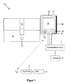
- FIG. 1 shows a lock 10, which is used in a wing system, so a wing. It comprises a profile cylinder 12 with cam 13 and Stulploch 14. Preferably at one end, a rotary knob 11 is placed on the profile cylinder 12.
- the rotary knob 11 is designed so that it is freely rotatable to the cam 13 is arranged.
- a self-sufficient power supply device 15 is used in the form of a battery or a rechargeable battery.
- the rotary knob 11 further includes a control circuit which energized when activated a coupled motor, not shown in the profile cylinder 12 so that it rotates with him mosationswirkverbundenen cam 13 in the unlocking of the connected, also not shown wing lock.
- the knob 11 includes for Activating the knob 11 a proximity sensor here in the form of a reader 19 with coupled reading antenna 20.
- the reader 19 is adapted to read data, for example, from a transponder code card and trigger their examination for authorization to activate the knob 11 or perform themselves.
- the reader 19 is coupled to the antenna 20 and the power supply device 15 in order to advantageously read out the data of the code card without contact.
- a display 17 is preferably arranged by way of example in the form of a light ring arranged behind LED.
- a communication interface is integrated here in the form of a radio module 18, for example, take the reader 19 contact with a remote communication interface here in the form of a trained as a radio node radio module 3 and above with a host system here in the form of a server 4 can.
- a temperature sensor 16 for example in the form of a thermistor, is arranged on or in the rotary knob 11 such that a current ambient temperature ⁇ akt can preferably be determined with reference to the entire rotary knob 11 with the aid of the sensor 16.
- an energy monitor 1 is coupled to the processor, which is also exemplarily bus-coupled with a central building 2.
- the method is based on pre-determined discharge curves for the particular type of power supply 15 at different ambient temperatures.
- the power of the power supply device decreases with decreasing temperature.
- the curves are preferably stored as tables advantageously in the host system, but may also be stored in the rotary knob 11.
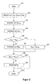
- a current ambient temperature ⁇ akt with respect to the rotary knob 11 is determined or measured in a step S2 by means of the sensor 16.
- both a current output voltage U akt and a current strength l akt of the energy supply device 15 are preferably determined or measured via a measuring circuit (not shown here). Since, due to the limited storage space, data sets can not be stored for each ambient temperature, an interpolation is preferably carried out between two discharge curves whose associated temperatures directly encompass the currently measured ambient temperature ⁇ akt with respect to the rotary knob 11, if the measured ambient temperature ⁇ akt none of the stored discharge curves. Temperatures corresponds.
- step S3 which maximum expected residual capacity K Rmax the energy supply device 15 still has at the measured temperature ⁇ akt . Since it is also known at what intervals on average activation of the rotary knob 11 is to be expected, it is possible to deduce the probable period of time, within which the knob 11 would continue to operate at a constant ambient temperature.
- the method determines in a subsequent step S4 which lowest ambient temperature ⁇ min is to be expected for the probable time duration. This can be done by means of a database containing, for example, for each day of the year the expected minimum ambient temperatures. Over a minimum consideration over the probable period, the lowest ambient temperature ⁇ min can be determined.
- step S5 it is checked in step S5 whether the minimum ambient temperature ⁇ min is smaller than the measured ambient temperature ⁇ akt or not. If this is the case (yes branch after step S5), the residual capacity is now determined as a probable residual capacity K Rw , now based on U akt and l akt and ⁇ min and in the manner as for ⁇ akt . Otherwise (no branch after step S6), ⁇ act already corresponds to the minimum ambient temperature, and the maximum expected residual capacity K Rmax is accordingly set only as a probable residual capacity K Rw .
- step S8 it is then checked in a subsequent step S8 whether the probable residual capacity K Rw falls below a predetermined minimum residual capacity K Rmin or not. If this is the case (yes branch after step S8), this is signaled for example via the display 17. Alternatively or additionally, the center 2 is informed. After that it is Procedure in a step S10 ended. Otherwise (no branch after step S8), the process is terminated immediately.
- the residual capacities K Rw , K Rmin , K Rmax are preferably data sets in the form of n-tuples. They preferably include the number of possible knob activations, the average pause between two activations, and the average duration of the respective activation. Duration and break can be summarized in a respective time value. Ie. the residual capacities K Rw , K Rmin , K Rmax are mapped by means of an associated number of activations. By means of simple multiplication of number and time, the probable, certainly present remaining life of the energy supply device 15 can be calculated.
- the number of activations has the advantage, even if the rotary knob 11 is activated less frequently or more frequently than the average, it is still safe to be able to determine the probable residual capacity K Rw .
- the remaining number of activations can be displayed, for example, in the center 2, in order to give service personnel the opportunity to recognize any upcoming change of the energy supply device 15.
- the process has a second decisive advantage. Due to the currently determined voltage U act or the current I akt , no problem occurs even with a partially discharged power supply device 15.
- the minimum ambient temperature ⁇ min does not necessarily have to be determined on the basis of (only) the future.
- existing weather forecast data can also be used for the future. Ie. for the determined maximum expected residual life or capacity K Rmax or the duration of the weather forecast, for example, for the next three days, whichever duration is shorter, the minimum predicted environmental temperature is used instead of other, for example, average ambient temperatures for that duration. This also makes it possible to better adapt the prediction accuracy with regard to the probable residual capacity K Rw to the prevailing weather conditions.
- the energy monitor 1 may be at least partially part of the rotary knob 11.
- the center 2 can be omitted.
- the couplings can be of any kind.
- the lock 10 or the rotary knob 11 may have an internal, preferably non-volatile memory in which data are stored legitimate code cards and belonging to authorized persons. It thus contains a database.
- the database is preferably used when reading and evaluating the data of the respective code card. In that case, the rotary knob 11 or a controller received therein will periodically contact the host system for updated data for to download the database. This has the advantage that it can be checked whether the knob 11 is functional.
- the host system triggers the controller to receive updated data. This reduces the communication effort and possibly the energy consumption of the knob 11th
- K Rmin there may be several such residual capacities , for example 500, 200, 100, 50, 20, 5 and 1 activation. This makes it possible to control the display 17 differently. If K Rw > 500, the rotary knob 11 can thus safely be activated more than 500 times, the display 17 remains dark. If K Rw > 0 and K Rw ⁇ 500, the display 17 flashes by way of example red, and always faster, the smaller the respective minimum residual capacity is, which falls below. If activation is no longer possible (K Rw ⁇ 1), the display 17 lights up permanently red as an example. Ie. it is possible to realize, so to speak, warnings regarding a decreasing residual capacity of the power supply device 15.
- the no-load and / or load voltage or the current consumption per activation cycle are measured.
- the capacity removal per cycle from the power supply device 15 can be taken into account, which allows a more accurate prediction of the probable residual capacity K Rw .
Landscapes
- Physics & Mathematics (AREA)
- Electromagnetism (AREA)
- Charge And Discharge Circuits For Batteries Or The Like (AREA)
- Lock And Its Accessories (AREA)
Abstract
Description
- Die Erfindung betrifft eine Überwachung für Drehknäufe mit einer autarken Energieversorgung und als Teil einer Flügelanlage, insbesondere batteriegespeiste Drehknäufe.
- Drehknäufe von Sicherheitszylindern werden bekanntermaßen eingesetzt, bei Aktivierung einen in einem zugeordneten Profilzylinder eines Flügelschlosses aufgenommenen Motor anzusteuern, einen Schließbart des Profilzylinders zumindest in Entriegelungsrichtung zu drehen. Nach Beenden der Aktivierung wird der Motor abgeschaltet. Die Aktivierung erfolgt typischerweise berührungslos beispielsweise mittels einer Codekarte exemplarisch in Form einer Transponderkarte, die an einen Leser des Drehknaufs angelegt oder an ihn angenähert wird und Berechtigungsdaten beinhaltet. Diese Daten werden vom Leser ausgelesen und auf Berechtigung, den jeweiligen Flügel öffnen zu dürfen, geprüft. Ist die Prüfung erfolgreich, wird der Drehknauf aktiviert, und der Flügel kann mithilfe des Motors entriegelt und damit geöffnet werden.
- Diese Art von Drehknäufen wird üblicherweise mittels einer oder eines innen angeordneten Batterie bzw. Akkumulators als Energieversorgungseinrichtung autark mit Energie versorgt. Die Energieversorgungseinrichtung entlädt sich dabei sowohl während des Zeitraums der Aktivierung als auch in den Zeiten dazwischen.
- Um zu verhindern, dass die Energieversorgungseinrichtung nicht mehr ausreichend Energie hat, den Drehknauf zu aktivieren oder gar die Berechtigungsdaten zu lesen, ist aus dem Stand der Technik bekannt, die Restkapazität der Energieversorgungseinrichtung zu überwachen, um einen eventuell notwendigen Wechsel der Energieversorgungseinrichtung anzeigen zu können.
- In der
DE 10 2006 020 309 A1 ist ein Verfahren zur Erkennung des Endes der Lebensdauer eines bestimmten Batterietyps beschrieben. Dabei werden zu Beginn des Verfahrens Grenzwertkriterien ausgewählt, die durch Messungen der Spannung an Batterieklemmen bestimmbar machen, ob die Batterie noch ausreichend Restkapazität hat oder nicht. Es werden Batteriespannung-Temperatur-Kennlinien genutzt, um die für die jeweilige Temperatur notwendige Spannung zu ermitteln. Wird die notwendige Spannung unterschritten, wird ein Zähler inkrementiert. Erreicht der Zähler einen vorbestimmten Grenzwert, kann ein Warnsignal abgegeben werden. Diese Lösung hat den Nachteil, dass die Batteriekapazität bereits nicht mehr ausreichen kann, obwohl der Zähler noch nicht den Grenzwert erreicht hat. Dies kann insbesondere passieren, wenn die Umgebungstemperatur in Bezug auf die Batterie beispielsweise über Nacht rapide fällt, sodass die Batterie keine ausreichende Kapazität mehr hat, obwohl sie am Vortag völlig ausgereicht hatte. - Die
DE 60 2004 010 203 T2 beschreibt ein Verfahren zur Berechnung der Restspeicherenergie einer Sekundärzelle. Über einen ziemlich komplexen Berechnungsalgorithmus kann ein Zeitpunkt der vollständigen Entladung ermittelt werden. Dabei wird von einer aktuell vorliegenden Temperatur ausgegangen. Dieses Verfahren funktioniert nicht, wenn sich die Temperatur zwischenzeitlich ändert. Es kann also auch hier vorkommen, dass die Batteriekapazität bereits nicht mehr ausreichen kann, obwohl der ermittelte Entladezeitpunkt noch nicht erreicht ist. - Aufgabe der Erfindung ist es, die Nachteile des Standes zumindest zu verringern.
- Diese Aufgabe wird durch den Gegenstand des Anspruchs 1 gelöst. Vorteilhafte Weiterbildungen der Erfindung sind in den Unteransprüchen angegeben.
- Eine erfindungsgemäße Flügelanlage weist einen bewegbaren Flügel mit einer Schließvorrichtung auf, die ein Flügelschloss umfasst. Das Flügelschloss ist mit einem Profilzylinder mit Schließbart versehen und verfügt über einen Drehknauf. Der Drehknauf ist zum Schließbart frei rotierbar angeordnet. Zudem kann er derart aktiviert werden, dass er für die Zeit der Aktivierung den im Profilzylinder angeordneten Entriegelungsmotor mit Energie versorgt, sodass dieser den mit ihm rotationswirkverbundenen Schließbart in Entriegelungsstellung dreht. D. h. ein Drehen des Motors führt zu einem Mitdrehen des Schließbarts. Ferner ist im Drehknauf eine autarke Energieversorgungseinrichtung in Form einer Batterie oder eines Akkumulators integriert. Der Drehknauf weist ferner eine Energieüberwachung auf oder ist mit dieser gekoppelt.
- Eine Aktivierung des Drehknaufs bei unterschiedlichen Temperaturen belastet die Energieversorgungseinrichtung unterschiedlich und kann daher zu einem unterschiedlichen Entladen der Energieversorgungseinrichtung pro Aktivierung führen. Zudem sinkt die von der Energieversorgungseinrichtung ausgehende Spannung mit sinkenden Umgebungstemperaturen. Bei einer Betriebsspannung von beispielsweise 3 V kann die Energieversorgungseinrichtung bei 10° C eine Spannung von 4 V liefern, wobei sie bei 0° C eine Spannung von beispielsweise 2,7 V liefert, sodass der Drehknauf nicht mehr sicher aktiviert werden kann. Fällt jetzt über Nacht die Umgebungstemperatur über Nacht nun auf die besagten 0 °C, kann die Kapazität der Energieversorgungseinrichtung also nicht mehr ausreichen, obwohl am Tage noch ausreichend Kapazität vorhanden war. Daher ist die Energieüberwachung erfindungsgemäß eingerichtet, eine aktuelle Umgebungstemperatur in Bezug auf die Energieversorgungseinheit sowie eine durch die Energieversorgungseinheit aktuell gelieferte Spannung und/oder Stromstärke zu ermitteln bzw. zu messen. Basierend darauf ermittelt die Energieüberwachung eine aktuelle, maximale erwartbare Restkapazität der Energieversorgungseinheit aus in einer Datenbank hinterlegten Referenzdaten für den jeweiligen Typ von Energieversorgungseinrichtung. Zudem ermittelt die Energieüberwachung für die ermittelte, maximale erwartbare Restkapazität eine zu erwartende minimale Umgebungstemperatur. D. h. wurde für die Restkapazität im September eine Restkapazität von zwei Monaten ermittelt, beinhaltet die Restkapazität beispielsweise den November, in dem Temperaturen unter 0° C möglich sind. Dementsprechend werden diese Temperaturen mit einbezogen. Wenn diese minimale Umgebungstemperatur niedriger ist als die aktuell vorliegende Umgebungstemperatur, ist die Restkapazität mit einiger Wahrscheinlichkeit geringer als die ermittelte, maximale erwartbare Restkapazität. Daher wird in dem Fall auf Basis dieser ermittelten, zu erwartenden minimalen Umgebungstemperatur nun in Verbindung mit der ermittelten aktuellen Spannung und/oder Stromstärke eine wahrscheinliche Restkapazität der Energieversorgungseinheit ermittelt. Schließlich signalisiert die Energieüberwachung beispielsweise einer gekoppelten Gebäudezentrale, wenn die ermittelte, wahrscheinliche Restkapazität eine vorbestimmte, für den Betrieb erforderliche minimale Restkapazität unterschreitet. D. h. es wird nicht die aktuell vorliegende Temperatur zugrunde gelegt sondern die während der künftigen, maximalen erwartbaren Restkapazität zu erwartende niedrigste Temperatur, wodurch mit wesentlich höherer Sicherheit davon ausgegangen werden kann, dass die Energieversorgungseinrichtung auch die wahrscheinliche Restkapazität bzw. daraus resultierende Restlebensdauer über reibungsfrei funktioniert. Zudem kann dadurch der Einfluss des Ruhebetriebs des Drehknaufs zwischen den Aktivierungen besser berücksichtigt werden.
- Vorzugsweise sind die Restkapazitäten jeweils durch eine Anzahl an Aktivierungen des Drehknaufs abgebildet. D. h. die Restkapazität ist eigentlich keine Zeitangabe sondern eine Angabe, wie oft der Drehknauf mit dieser Energieversorgungseinrichtung noch sicher aktiviert werden kann. Dies hat den Vorteil, dass die Energieversorgungseinrichtung je nach Aktivierungsfrequenz länger oder kürzer funktioniert, dies aber immer ermittelt werden kann. Eine resultierende Restlebensdauer der Energieversorgungseinrichtung lässt sich beispielsweise mittels Multiplizierens der Restkapazität mit der durchschnittlichen Pause zwischen unmittelbar aufeinander folgenden Aktivierungen vorzugsweise plus einer durchschnittlichen Dauer der Aktivierung ermittelt werden.
- Die aktuelle Umgebungstemperatur wird vorzugsweise über einen sich thermisch verändernden elektrischen Widerstand ermittelt, was eine sehr einfache Methode darstellt.
- Alternativ oder zusätzlich wird zur Ermittlung der zu erwartenden minimalen Umgebungstemperatur vorzugsweise ein niedrigster Umgebungstemperatur-Wert innerhalb eines vorbestimmten, dem Zeitpunkt des Ermittelns von Spannung und/oder Stromstärke unmittelbar vorausgegangenen Zeitraums mit einbezogen. Dies hat den Vorteil, beispielsweise bei kalten Sommermonaten dies in die Ermittlung der minimalen Umgebungstemperatur einfließen zu lassen.
- Zusätzlich oder alternativ können auch Wettervorhersagedaten in Bezug auf die ermittelte maximale erwartbare Restkapazität bzw. Restlebensdauer der Energieversorgungseinrichtung, sofern dies möglich ist, oder hinsichtlich des Zeitraums der Wettervorhersage zugrunde gelegt werden. Dies hat den Vorteil, künftig zu erwartende Temperaturen mit einzubeziehen, insbesondere, wenn diese vom Durchschnitt abweichen. Bei den Wettervorhersagedaten wird entweder die ermittelte maximale erwartbare Restlebensdauer oder der Zeitraum der Wettervorhersage zugrunde gelegt, je nachdem welche Zeitspanne geringer ist.
- Weitere Merkmale und Vorteile der Erfindung ergeben sich aus der nachfolgenden Beschreibung bevorzugter Ausführungsformen. Es zeigen:
- Figur 1
- ein Schloss gemäß einer Ausführungsform der Erfindung,
- Figur 2
- ein Verfahren zum Ermitteln der Restkapazität der Energie- versorgungseinrichtung von
Figur 1 gemäß einer Ausfüh- rungsform der Erfindung. -
Figur 1 zeigt ein Schloss 10, das in eine Flügelanlage, also einen Flügel, eingesetzt ist. Es umfasst einen Profilzylinder 12 mit Schließbart 13 und Stulploch 14. Vorzugsweise einerends ist auf den Profilzylinder 12 ein Drehknauf 11 aufgesetzt. - Der Drehknauf 11 ist so gestaltet, dass er frei rotierbar zum Schließbart 13 angeordnet ist. Im Drehknauf 11 ist eine autarke Energieversorgungseinrichtung 15 in Form einer Batterie oder eines Akkumulators eingesetzt. Der Drehknauf 11 weist ferner eine Steuerschaltung auf, die bei Aktivierung einen gekoppelten, nicht dargestellten Motor im Profilzylinder 12 derart bestromt, dass dieser den mit ihm rotationswirkverbundenen Schließbart 13 in Entriegelungsrichtung des angeschlossenen, ebenfalls nicht weiter dargestellten Flügelschlosses dreht. Der Drehknauf 11 umfasst zum Aktivieren des Drehknaufs 11 einen Näherungssensor hier in Form eines Lesers 19 mit gekoppelter Leseantenne 20. Der Leser 19 ist eingerichtet, Daten beispielsweise von einer Transponder-Codekarte zu lesen und deren Prüfung auf Berechtigung zum Aktivieren des Drehknaufs 11 auszulösen oder selbst durchzuführen. Der Leser 19 ist mit der Antenne 20 und der Energieversorgungseinrichtung 15 gekoppelt, um die Daten der Codekarte vorteilhafterweise berührungsfrei auslesen zu können.
- An einer dem Profilzylinder 12 abgewandten Seite des Drehknaufs 11 ist vorzugsweise eine Anzeige 17 beispielhaft in Form eines Leuchtrings mit dahinter angeordneter LED angeordnet.
- Ferner ist in den Drehknauf 11 eine Kommunikationsschnittstelle hier in Form eines Funkmoduls 18 integriert, über die beispielsweise der Leser 19 Kontakt mit einer entfernten Kommunikationsschnittstelle hier in Form eines als Funkknoten ausgebildeten Funkmoduls 3 und darüber mit einem Host-System hier in Form eines Servers 4 aufnehmen kann.
- Vorzugsweise ist am oder im Drehknauf 11 ein Temperatursensor 16 beispielsweise in Form eines Thermistors so angeordnet, dass mithilfe des Sensors 16 eine aktuelle Umgebungstemperatur ϑakt vorzugsweise in Bezug auf den gesamten Drehknauf 11 ermittelt werden kann.
- Schließlich ist hier mit dem Drehknauf 11 eine Energieüberwachung 1 mit Prozessor gekoppelt, die zudem exemplarisch mit einer Gebäudezentrale 2 busgekoppelt ist.
- Um eine wahrscheinliche Restkapazität KRw der Energieversorgungseinrichtung 15 ermitteln zu können, ist ein Verfahren gemäß
Figur 2 vorgesehen, das vorzugsweise periodisch wiederholt wird. - Das Verfahren basiert auf der Grundlage vorab ermittelter Entladekurven für den jeweiligen Typ von Energieversorgungseinrichtung 15 bei verschiedenen Umgebungstemperaturen. Bekanntermaßen verringert sich die Leistung der Energieversorgungseinrichtung mit sinkender Temperatur. Die Kurven sind vorzugsweise als Tabellen vorteilhafterweise im Host-System abgelegt, können aber auch im Drehknauf 11 abgelegt sein.
- Nach dem Start in Schritt S1 wird in einem Schritt S2 mittels des Sensors 16 eine aktuelle Umgebungstemperatur ϑakt bezüglich des Drehknaufs 11 ermittelt bzw. gemessen. Zugleich werden über eine hier nicht weiter dargestellte Messschaltung vorzugsweise sowohl eine aktuelle Ausgangsspannung Uakt als auch eine Stromstärke lakt der Energieversorgungseinrichtung 15 ermittelt bzw. gemessen. Da aufgrund des begrenzten Speicherplatzes nicht für jede Umgebungstemperatur Datensätze abgelegt werden können, wird vorzugsweise eine Interpolation zwischen zwei Entladekurven durchgeführt, deren zugeordnete Temperaturen die aktuell gemessene Umgebungstemperatur ϑakt bezüglich des Drehknaufs 11 unmittelbar einfassen, wenn die gemessene Umgebungstemperatur ϑakt keiner der abgelegten Entladekurven-Temperaturen entspricht.
- Im System ist für jede Entladungskurve aufgrund gespeicherter, minimaler Spannungs- und/oder Stromstärkewerte bekannt, ab wann die Funktionssicherheit des Drehknaufs 11 nicht mehr gewährleistet werden kann.
- Darauf basierend wird in einem Schritt S3 ermittelt, welche maximale erwartbare Restkapazität KRmax die Energieversorgungseinrichtung 15 bei der gemessenen Temperatur ϑakt noch hat. Da zudem bekannt ist, in welchen Zeitabständen durchschnittlich eine Aktivierung des Drehknaufs 11 zu erwarten ist, kann auf die wahrscheinliche Zeitdauer geschlossen werden, innerhalb der der Drehknauf 11 bei konstanter Umgebungstemperatur weiter funktionieren würde.
- Nun treten aber Temperaturschwankungen beispielsweise zwischen Tag und Nacht auf. D. h. niedrige Nachttemperaturen können zu einer verringerten Restkapazität und damit zu einer geringeren Restlebensdauer der Energieversorgungseinrichtung 15 führen. Um dies in den Griff zu bekommen, wird im Rahmen des Verfahrens in einem nachfolgenden Schritt S4 ermittelt, welche niedrigste Umgebungstemperatur ϑmin für die wahrscheinliche Zeitdauer zu erwarten ist. Dies kann mittels einer Datenbank erfolgen, die beispielsweise für jeden Tag des Jahres die zu erwartenden minimalen Umgebungstemperaturen enthält. Über eine Minimumbetrachtung über den wahrscheinlichen Zeitraum hinweg kann so die niedrigste Umgebungstemperatur ϑmin ermittelt werden.
- Nun wird in Schritt S5 geprüft, ob die minimale Umgebungstemperatur ϑmin kleiner als die gemessene Umgebungstemperatur ϑakt ist oder nicht. Ist dies der Fall (ja-Zweig nach Schritt S5), wird die Restkapazität nunmehr als wahrscheinliche Restkapazität KRw ermittelt, nunmehr basierend auf Uakt und lakt sowie ϑmin und in der Art wie für ϑakt. Andernfalls (nein-Zweig nach Schritt S6) entspricht ϑakt bereits der minimalen Umgebungstemperatur, und die maximale erwartbare Restkapazität KRmax wird dementsprechend nur noch als wahrscheinliche Restkapazität KRw gesetzt.
- In beiden Fällen wird daraufhin in einem nachfolgenden Schritt S8 geprüft, ob die wahrscheinliche Restkapazität KRw eine vorgegebene minimale Restkapazität KRmin unterschreitet oder nicht. Ist dies der Fall (ja-Zweig nach Schritt S8), wird dies beispielsweise über die Anzeige 17 signalisiert. Alternativ oder zusätzlich wird die Zentrale 2 informiert. Danach ist das Verfahren in einem Schritt S10 beendet. Andernfalls (nein-Zweig nach Schritt S8) ist das Verfahren sofort beendet.
- Die Restkapazitäten KRw, KRmin, KRmax sind vorzugsweise Datensätze in Form von n-Tupeln. Sie umfassen vorzugsweise die Anzahl an möglichen Drehknauf-Aktivierungen, die durchschnittliche Pause zwischen zwei Aktivierungen und die durchschnittliche Dauer der jeweiligen Aktivierung. Dauer und Pause können in einem jeweiligen Zeitwert zusammengefasst sein. D. h. die Restkapazitäten KRw, KRmin, KRmax werden mittels einer jeweils zugehörigen Anzahl an Aktivierungen abgebildet. Mittels einfachen Multiplizierens von Anzahl und Zeit kann die wahrscheinliche, sicher vorliegende Restlebensdauer der Energieversorgungseinrichtung 15 berechnet werden. Die Anzahl an Aktivierungen hat den Vorteil, auch wenn der Drehknauf 11 seltener oder häufiger als im Durchschnitt aktiviert wird, weiterhin sicher die wahrscheinliche Restkapazität KRw ermitteln zu können. Zudem kann die Restanzahl an Aktivierungen beispielsweise in der Zentrale 2 angezeigt werden, um Servicepersonal die Möglichkeit zu geben, einen etwaig anstehenden Wechsel der Energieversorgungseinrichtung 15 zu erkennen.
- Das Verfahren hat einen zweiten entscheidenden Vorteil. Aufgrund der aktuell ermittelten Spannung Uakt bzw. der Stromstärke lakt tritt auch bei einer teilentladenen Energieversorgungseinrichtung 15 kein Problem auf.
- Die minimale Umgebungstemperatur ϑmin muss nicht zwangsläufig auf Basis (nur) der Zukunft ermittelt werden.
- Zusätzlich oder alternativ wird die minimale Umgebungstemperatur ϑmin innerhalb eines vorbestimmten, unmittelbar vergangenen Zeitraums, beispielsweise der letzten drei Tage, ermittelt. Dies bietet die Möglichkeit, Temperaturen in Betracht zu ziehen, die vom Durchschnitt abweichen. Damit kann die Vorhersagegenauigkeit hinsichtlich der wahrscheinlichen Restkapazität KRw verbessert werden.
- Wiederum zusätzlich oder alternativ können für die Zukunft auch vorhandene Wettervorhersagedaten genutzt werden. D. h. für die ermittelte maximale erwartbare Restlebensdauer bzw. -kapazität KRmax oder die Dauer der Wettervorhersage, beispielsweise für die nächsten drei Tage, je nachdem welche Dauer kürzer ist, wird die minimal vorhergesagte Vorhersage-Umgebungstemperatur anstelle anderer, beispielsweise durchschnittlicher Umgebungstemperaturen für diese Dauer genutzt. Auch dadurch lässt sich die Vorhersagegenauigkeit hinsichtlich der wahrscheinlichen Restkapazität KRw besser an die jeweils vorliegenden Wetterverhältnisse anpassen.
- Die Erfindung ist nicht auf die vorbeschriebenen Ausführungen beschränkt.
- Die Energieüberwachung 1 kann zumindest teilweise Teil des Drehknaufs 11 sein. Die Zentrale 2 kann entfallen. Die Kopplungen können jeglicher Art sein.
- Das Schloss 10 bzw. der Drehknauf 11 kann über einen internen, vorzugsweise nichtflüchtigen Speicher verfügen, in dem Daten berechtigter Codekarten und dazugehörig von berechtigten Personen abgelegt sind. Er beinhaltet somit eine Datenbank. Die Datenbank wird vorzugsweise beim Lesen und Auswerten der Daten der jeweiligen Codekarte genutzt. In dem Fall nimmt der Drehknauf 11 bzw. eine darin aufgenommene Steuerung regelmäßig mit dem Host-System Kontakt auf, um aktualisierte Daten für die Datenbank herunterzuladen. Dies hat den Vorteil, dass dabei überprüft werden kann, ob der Drehknauf 11 funktionstüchtig ist.
- Alternativ triggert das Host-System die Steuerung an, aktualisierte Daten zu empfangen. Dies vermindert den Kommunikationsaufwand und unter Umständen auch den Energieverbrauch des Drehknaufs 11.
- Zudem kann es anstelle einer einzigen minimalen Restkapazität KRmin mehrere derartige Restkapazitäten geben, beispielsweise 500, 200, 100, 50, 20, 5 und 1 Aktivierung. Dies ermöglicht, die Anzeige 17 unterschiedlich anzusteuern. Ist KRw > 500, kann der Drehknauf 11 also sicher über 500 Mal aktiviert werden, bleibt die Anzeige 17 dunkel. Gilt KRw > 0 und KRw < 500, blinkt die Anzeige 17 beispielhaft rot, und zwar immer schneller, je kleiner die jeweilige minimale Restkapazität ist, die unterschritten wird. Ist keine Aktivierung mehr möglich (KRw < 1), leuchtet die Anzeige 17 exemplarisch dauerhaft rot. D. h. es lassen sich sozusagen Vorwarnungen hinsichtlich einer sich verringernden Restkapazität der Energieversorgungseinrichtung 15 realisieren.
- Als Spannung bzw. Stromstärke werden die Leerlauf, und/oder Lastspannung bzw. die Stromaufnahme pro Aktivierungs-Zyklus gemessen.
- Ferner kann die Kapazitätsentnahme pro Zyklus aus der Energieversorgungseinrichtung 15 berücksichtigt werden, was eine genauere Vorhersage der wahrscheinlichen Restkapazität KRw ermöglicht.
- Mit der Erfindung ist somit eine sehr sichere Vorhersage möglich, wie lang die Energieversorgungseinrichtung 15 noch mit Sicherheit funktioniert.
-
- 1
- Energieüberwachung
- 2
- Zentrale
- 3
- Funkmodul
- 4
- Server
- 10
- Schloss
- 11
- Drehknauf
- 12
- Profilzylinder
- 13
- Schließbart
- 14
- Stulploch
- 15
- Energieversorgungseinrichtung
- 16
- Temperatursensor
- 17
- Anzeige
- 18
- Funkmodul
- 19
- Leser
- 20
- Antenne
- KRmax
- maximale erwartbare Restkapazität
- KRw
- wahrscheinliche Restkapazität
- KRmin
- minimale Restkapazität
- Uakt
- aktuell anliegende Spannung
- Iakt
- aktuell anliegende Stromstärke
- ϑakt
- aktuelle Umgebungstemperatur
- ϑmin
- minimale Umgebungstemperatur
- Si; i ∈ N
- Schritt
Claims (4)
- Flügelanlage, aufweisend• einen bewegbaren Flügel mit einer Schließvorrichtung, umfassend ein Flügelschloss (10) mit- einem Profilzylinder (12) mit Schließbart (13) und- einem Drehknauf (11), der· zum Schließbart (13) frei rotierbar angeordnet ist,· derart aktivierbar ist, dass der Drehknauf (11) für die Zeit der Aktivierung einen mit dem Schließbart (13) rotationswirkverbundenen Motor derart mit Energie versorgt, dass dieser den Schließbart (13) in eine vorbestimmte Richtung rotiert,· eine autarke Energieversorgungseinrichtung (15) aufweist und· eine Energieüberwachung (1) aufweist oder mit dieser gekoppelt ist,• wobei die Energieüberwachung (1) eingerichtet ist,- eine aktuelle Umgebungstemperatur (ϑakt) in Bezug auf die Energieversorgungseinrichtung (15) zu ermitteln (S2),- eine durch die Energieversorgungseinrichtung (15) aktuell gelieferte Spannung (Uakt) und/oder Stromstärke (Iakt) zu ermitteln (S3),- eine aktuelle, maximale erwartbare Restkapazität (KRmax) der Energieversorgungseinrichtung (15) aufgrund der gemessenen und ermittelten Werte aus Referenzdaten zu ermitteln (S4),- eine zu erwartende minimale Umgebungstemperatur (ϑmin) innerhalb der ermittelten maximalen erwartbaren Restkapazität (KRmax) zu ermitteln (S5),- eine wahrscheinliche Restkapazität (KRw) der Energieversorgungseinrichtung (15) aufgrund der ermittelten aktuellen Spannung (Uakt) und/oder Stromstärke (Iakt) sowie der ermittelten, zu erwartenden minimalen Umgebungstemperatur (ϑmin) zu ermitteln (S6) und- zu signalisieren (S7), wenn die ermittelte, wahrscheinliche Restkapazität (KRw) eine vorbestimmte minimale Restkapazität (KRmin) unterschreitet.
- Anlage gemäß Anspruch 1, wobei die Restkapazitäten (KRw, KRmax, KRmin) jeweils durch eine Anzahl an Aktivierungen des Drehknaufs (11) abgebildet sind.
- Anlage gemäß Anspruch 1 oder 2, wobei die aktuelle Umgebungstemperatur (ϑakt) über einen sich thermisch verändernden elektrischen Widerstand ermittelt wird.
- Anlage gemäß einem der vorhergehenden Ansprüche, wobei die zu erwartende minimale Umgebungstemperatur (ϑmin) einem niedrigsten Temperaturwert• innerhalb eines vorbestimmten, dem Zeitpunkt des Ermittelns der Werte unmittelbar vorausgegangenen Zeitraums und/oder• aus Wettervorhersagedaten hinsichtlich- der ermittelten maximalen erwartbaren Restkapazität (KRmax) oder- dem Zeitraum der Wettervorhersage entspricht,• wobei- der Wettervorhersage-Zeitraum zugrunde gelegt wird, wenn die ermittelte maximale erwartbare Restkapazität (KRmax) für den Wettervorhersage-Zeitraum ausreicht, und- andernfalls die ermittelte maximale erwartbare Restkapazität (KRmax) zugrunde gelegt wird.
Applications Claiming Priority (1)
| Application Number | Priority Date | Filing Date | Title |
|---|---|---|---|
| DE102010037876A DE102010037876A1 (de) | 2010-09-30 | 2010-09-30 | Überwachung für Drehknäufe mit einer autarken Energieversorgung |
Publications (2)
| Publication Number | Publication Date |
|---|---|
| EP2436857A1 true EP2436857A1 (de) | 2012-04-04 |
| EP2436857B1 EP2436857B1 (de) | 2014-03-05 |
Family
ID=44905251
Family Applications (1)
| Application Number | Title | Priority Date | Filing Date |
|---|---|---|---|
| EP11007554.6A Not-in-force EP2436857B1 (de) | 2010-09-30 | 2011-09-16 | Flügelanlage mit einer Schliessvorrichtung und einer Energieüberwachung für einen Drehknauf mit einer autarken Energieversorgung |
Country Status (3)
| Country | Link |
|---|---|
| EP (1) | EP2436857B1 (de) |
| DE (1) | DE102010037876A1 (de) |
| ES (1) | ES2468865T3 (de) |
Cited By (1)
| Publication number | Priority date | Publication date | Assignee | Title |
|---|---|---|---|---|
| CN106355720A (zh) * | 2016-09-29 | 2017-01-25 | 广州广电银通金融电子科技有限公司 | 一种动态密码电子锁的电量远程监控管理系统及方法 |
Citations (7)
| Publication number | Priority date | Publication date | Assignee | Title |
|---|---|---|---|---|
| EP0994362A2 (de) * | 1998-10-15 | 2000-04-19 | VB Autobatterie GmbH | Verfahren zur Bestimmung des Ladezustandes und der Hochstrombelastbarkeit von Batterien |
| DE10045631A1 (de) * | 2000-06-27 | 2002-01-17 | Schulte Zylinderschl Gmbh | Schließzylinder mit dem Schließzylindergehäuse angeordneter Antenne |
| US20020093312A1 (en) * | 2000-11-27 | 2002-07-18 | Yeon-Chul Choo | Remaining battery capacity corrector and controlling method therefor |
| DE10209037A1 (de) * | 2002-03-02 | 2003-10-02 | Buga Schliessysteme Ag | Verfahren und Vorrichtung zum Überwachen der Spannung einer Batterie |
| DE102006020309A1 (de) | 2005-05-20 | 2006-11-23 | Siemens Vdo Automotive S.A.S. | Verfahren zur Erkennung des Endes der Lebensdauer eines bestimmten Batterietyps |
| DE602004010203T2 (de) | 2003-07-29 | 2008-10-02 | Sony Corp. | Verfahren zur Berechnung der Restspeicherenergie einer Sekundärzelle und Batterieblock |
| WO2009148160A1 (ja) * | 2008-06-06 | 2009-12-10 | 株式会社 明電舎 | キャパシタの余寿命診断装置および余寿命診断装置を備えた電力補償装置 |
-
2010
- 2010-09-30 DE DE102010037876A patent/DE102010037876A1/de not_active Withdrawn
-
2011
- 2011-09-16 ES ES11007554.6T patent/ES2468865T3/es active Active
- 2011-09-16 EP EP11007554.6A patent/EP2436857B1/de not_active Not-in-force
Patent Citations (8)
| Publication number | Priority date | Publication date | Assignee | Title |
|---|---|---|---|---|
| EP0994362A2 (de) * | 1998-10-15 | 2000-04-19 | VB Autobatterie GmbH | Verfahren zur Bestimmung des Ladezustandes und der Hochstrombelastbarkeit von Batterien |
| DE10045631A1 (de) * | 2000-06-27 | 2002-01-17 | Schulte Zylinderschl Gmbh | Schließzylinder mit dem Schließzylindergehäuse angeordneter Antenne |
| US20020093312A1 (en) * | 2000-11-27 | 2002-07-18 | Yeon-Chul Choo | Remaining battery capacity corrector and controlling method therefor |
| DE10209037A1 (de) * | 2002-03-02 | 2003-10-02 | Buga Schliessysteme Ag | Verfahren und Vorrichtung zum Überwachen der Spannung einer Batterie |
| DE602004010203T2 (de) | 2003-07-29 | 2008-10-02 | Sony Corp. | Verfahren zur Berechnung der Restspeicherenergie einer Sekundärzelle und Batterieblock |
| DE102006020309A1 (de) | 2005-05-20 | 2006-11-23 | Siemens Vdo Automotive S.A.S. | Verfahren zur Erkennung des Endes der Lebensdauer eines bestimmten Batterietyps |
| WO2009148160A1 (ja) * | 2008-06-06 | 2009-12-10 | 株式会社 明電舎 | キャパシタの余寿命診断装置および余寿命診断装置を備えた電力補償装置 |
| EP2290383A1 (de) * | 2008-06-06 | 2011-03-02 | Meidensha Corporation | Einrichtung zur diagnose der verbleibenden lebensdauer eines kondensators und elektrische stromkompensationseinrichtung mit der einrichtung zur diagnose der verbleibenden lebensdauer |
Cited By (1)
| Publication number | Priority date | Publication date | Assignee | Title |
|---|---|---|---|---|
| CN106355720A (zh) * | 2016-09-29 | 2017-01-25 | 广州广电银通金融电子科技有限公司 | 一种动态密码电子锁的电量远程监控管理系统及方法 |
Also Published As
| Publication number | Publication date |
|---|---|
| EP2436857B1 (de) | 2014-03-05 |
| ES2468865T3 (es) | 2014-06-17 |
| DE102010037876A1 (de) | 2012-04-05 |
Similar Documents
| Publication | Publication Date | Title |
|---|---|---|
| DE19853013B4 (de) | Vorrichtung zur Unterstützung der Wartung/Inspektion | |
| DE102007021921B4 (de) | Vorrichtung zum Überwachen eines Energiespeichers | |
| DE19932147A1 (de) | Elektronisches System zur Erfassung und Kontrolle von Patientendaten | |
| EP3293315A1 (de) | Vorrichtung zum überwachen eines hydranten | |
| EP2718907B1 (de) | Verfahren und system zur überwachung der integrität von frachtbehältnissen | |
| EP3479362B1 (de) | Schliessanordnung für einen schaltschrank und ein entsprechendes verfahren | |
| EP3637064B1 (de) | Batteriebetriebenes füllstandmessgerät mit restlebensdauerbestimmungsvorrichtung | |
| DE102014113832A1 (de) | Daten- und Messerfassungsvorrichtung für einen Türgriff sowie Verfahren dazu | |
| DE202010006963U1 (de) | Mobiles Datengerät und System zum Lesen von Daten von einem Datenträger | |
| EP2098998B1 (de) | Zutrittskontrollsystem und Verfahren zum Betrieb eines solchen Systems | |
| EP3306023A1 (de) | System zum messen, überwachen und steuern von beweglichen und schliessbaren bauteilen | |
| EP2436857B1 (de) | Flügelanlage mit einer Schliessvorrichtung und einer Energieüberwachung für einen Drehknauf mit einer autarken Energieversorgung | |
| EP4031736A1 (de) | Vorrichtung und verfahren zur identifikation und zustandsüberwachung einer zu überwachenden einrichtung mit einem öffenbaren und verschliessbaren flügelelement | |
| EP3306173B1 (de) | Sicherheitssystem mit einem sicherheitsschalter | |
| EP1855253A2 (de) | Montageanordnung sowie Erfassungssystem mit einer solchen Anordnung | |
| DE112022004061T5 (de) | Containerisiertes batteriesystem und antikondensations-steuersystem und verfahren dafür | |
| EP2270452A2 (de) | Vorrichtung zur Temparaturüberwachung in elektrischen Anlagen, elektrische Anlage mit einer derartigen Vorrichtung sowie Verfahren zum Betrieb derselben | |
| EP1602078B1 (de) | Zutrittskontrollsystem und verfahren zum betrieb eines solchen zutrittskontrollsystemes | |
| WO2020193073A1 (de) | System zur bereitstellung von betriebsdaten | |
| DE102017119563A1 (de) | Anlage zur Gewährleistung einer komplexen Überwachung mobiler Wohnobjekte | |
| DE102011054154A1 (de) | Vorrichtung zur Speicherung und Bereitstellung von fahrzeugbezogenen Daten und zugehöriges Verfahren | |
| DE10214472A1 (de) | Einrichtung zur Identifikation von Fahrzeugreifen | |
| WO2003038764A2 (de) | Sicherheitseinrichtung | |
| DE102005051452A1 (de) | Verfahren und Vorrichtung zur automatischen Ermittlung von Wartungszeitpunkten | |
| DE202013002618U1 (de) | Batterieüberwachungsvorrichtung |
Legal Events
| Date | Code | Title | Description |
|---|---|---|---|
| PUAI | Public reference made under article 153(3) epc to a published international application that has entered the european phase |
Free format text: ORIGINAL CODE: 0009012 |
|
| AK | Designated contracting states |
Kind code of ref document: A1 Designated state(s): AL AT BE BG CH CY CZ DE DK EE ES FI FR GB GR HR HU IE IS IT LI LT LU LV MC MK MT NL NO PL PT RO RS SE SI SK SM TR |
|
| AX | Request for extension of the european patent |
Extension state: BA ME |
|
| 17P | Request for examination filed |
Effective date: 20121004 |
|
| RIC1 | Information provided on ipc code assigned before grant |
Ipc: E05B 47/06 20060101AFI20130705BHEP |
|
| GRAP | Despatch of communication of intention to grant a patent |
Free format text: ORIGINAL CODE: EPIDOSNIGR1 |
|
| INTG | Intention to grant announced |
Effective date: 20131009 |
|
| GRAS | Grant fee paid |
Free format text: ORIGINAL CODE: EPIDOSNIGR3 |
|
| GRAA | (expected) grant |
Free format text: ORIGINAL CODE: 0009210 |
|
| AK | Designated contracting states |
Kind code of ref document: B1 Designated state(s): AL AT BE BG CH CY CZ DE DK EE ES FI FR GB GR HR HU IE IS IT LI LT LU LV MC MK MT NL NO PL PT RO RS SE SI SK SM TR |
|
| REG | Reference to a national code |
Ref country code: GB Ref legal event code: FG4D Free format text: NOT ENGLISH |
|
| REG | Reference to a national code |
Ref country code: CH Ref legal event code: EP |
|
| REG | Reference to a national code |
Ref country code: AT Ref legal event code: REF Ref document number: 655009 Country of ref document: AT Kind code of ref document: T Effective date: 20140315 |
|
| REG | Reference to a national code |
Ref country code: IE Ref legal event code: FG4D Free format text: LANGUAGE OF EP DOCUMENT: GERMAN |
|
| REG | Reference to a national code |
Ref country code: DE Ref legal event code: R096 Ref document number: 502011002260 Country of ref document: DE Effective date: 20140417 |
|
| REG | Reference to a national code |
Ref country code: ES Ref legal event code: FG2A Ref document number: 2468865 Country of ref document: ES Kind code of ref document: T3 Effective date: 20140617 |
|
| REG | Reference to a national code |
Ref country code: NL Ref legal event code: VDEP Effective date: 20140305 |
|
| PG25 | Lapsed in a contracting state [announced via postgrant information from national office to epo] |
Ref country code: NO Free format text: LAPSE BECAUSE OF FAILURE TO SUBMIT A TRANSLATION OF THE DESCRIPTION OR TO PAY THE FEE WITHIN THE PRESCRIBED TIME-LIMIT Effective date: 20140605 Ref country code: LT Free format text: LAPSE BECAUSE OF FAILURE TO SUBMIT A TRANSLATION OF THE DESCRIPTION OR TO PAY THE FEE WITHIN THE PRESCRIBED TIME-LIMIT Effective date: 20140305 |
|
| REG | Reference to a national code |
Ref country code: LT Ref legal event code: MG4D |
|
| PG25 | Lapsed in a contracting state [announced via postgrant information from national office to epo] |
Ref country code: CY Free format text: LAPSE BECAUSE OF FAILURE TO SUBMIT A TRANSLATION OF THE DESCRIPTION OR TO PAY THE FEE WITHIN THE PRESCRIBED TIME-LIMIT Effective date: 20140305 Ref country code: SE Free format text: LAPSE BECAUSE OF FAILURE TO SUBMIT A TRANSLATION OF THE DESCRIPTION OR TO PAY THE FEE WITHIN THE PRESCRIBED TIME-LIMIT Effective date: 20140305 Ref country code: FI Free format text: LAPSE BECAUSE OF FAILURE TO SUBMIT A TRANSLATION OF THE DESCRIPTION OR TO PAY THE FEE WITHIN THE PRESCRIBED TIME-LIMIT Effective date: 20140305 |
|
| PG25 | Lapsed in a contracting state [announced via postgrant information from national office to epo] |
Ref country code: HR Free format text: LAPSE BECAUSE OF FAILURE TO SUBMIT A TRANSLATION OF THE DESCRIPTION OR TO PAY THE FEE WITHIN THE PRESCRIBED TIME-LIMIT Effective date: 20140305 Ref country code: RS Free format text: LAPSE BECAUSE OF FAILURE TO SUBMIT A TRANSLATION OF THE DESCRIPTION OR TO PAY THE FEE WITHIN THE PRESCRIBED TIME-LIMIT Effective date: 20140305 Ref country code: LV Free format text: LAPSE BECAUSE OF FAILURE TO SUBMIT A TRANSLATION OF THE DESCRIPTION OR TO PAY THE FEE WITHIN THE PRESCRIBED TIME-LIMIT Effective date: 20140305 |
|
| PG25 | Lapsed in a contracting state [announced via postgrant information from national office to epo] |
Ref country code: EE Free format text: LAPSE BECAUSE OF FAILURE TO SUBMIT A TRANSLATION OF THE DESCRIPTION OR TO PAY THE FEE WITHIN THE PRESCRIBED TIME-LIMIT Effective date: 20140305 Ref country code: NL Free format text: LAPSE BECAUSE OF FAILURE TO SUBMIT A TRANSLATION OF THE DESCRIPTION OR TO PAY THE FEE WITHIN THE PRESCRIBED TIME-LIMIT Effective date: 20140305 Ref country code: IS Free format text: LAPSE BECAUSE OF FAILURE TO SUBMIT A TRANSLATION OF THE DESCRIPTION OR TO PAY THE FEE WITHIN THE PRESCRIBED TIME-LIMIT Effective date: 20140705 Ref country code: BG Free format text: LAPSE BECAUSE OF FAILURE TO SUBMIT A TRANSLATION OF THE DESCRIPTION OR TO PAY THE FEE WITHIN THE PRESCRIBED TIME-LIMIT Effective date: 20140605 Ref country code: RO Free format text: LAPSE BECAUSE OF FAILURE TO SUBMIT A TRANSLATION OF THE DESCRIPTION OR TO PAY THE FEE WITHIN THE PRESCRIBED TIME-LIMIT Effective date: 20140305 Ref country code: CZ Free format text: LAPSE BECAUSE OF FAILURE TO SUBMIT A TRANSLATION OF THE DESCRIPTION OR TO PAY THE FEE WITHIN THE PRESCRIBED TIME-LIMIT Effective date: 20140305 |
|
| PG25 | Lapsed in a contracting state [announced via postgrant information from national office to epo] |
Ref country code: SK Free format text: LAPSE BECAUSE OF FAILURE TO SUBMIT A TRANSLATION OF THE DESCRIPTION OR TO PAY THE FEE WITHIN THE PRESCRIBED TIME-LIMIT Effective date: 20140305 Ref country code: PL Free format text: LAPSE BECAUSE OF FAILURE TO SUBMIT A TRANSLATION OF THE DESCRIPTION OR TO PAY THE FEE WITHIN THE PRESCRIBED TIME-LIMIT Effective date: 20140305 |
|
| REG | Reference to a national code |
Ref country code: DE Ref legal event code: R097 Ref document number: 502011002260 Country of ref document: DE |
|
| PG25 | Lapsed in a contracting state [announced via postgrant information from national office to epo] |
Ref country code: PT Free format text: LAPSE BECAUSE OF FAILURE TO SUBMIT A TRANSLATION OF THE DESCRIPTION OR TO PAY THE FEE WITHIN THE PRESCRIBED TIME-LIMIT Effective date: 20140707 |
|
| PLBE | No opposition filed within time limit |
Free format text: ORIGINAL CODE: 0009261 |
|
| STAA | Information on the status of an ep patent application or granted ep patent |
Free format text: STATUS: NO OPPOSITION FILED WITHIN TIME LIMIT |
|
| REG | Reference to a national code |
Ref country code: DE Ref legal event code: R081 Ref document number: 502011002260 Country of ref document: DE Owner name: DORMAKABA DEUTSCHLAND GMBH, DE Free format text: FORMER OWNER: DORMA GMBH + CO. KG, 58256 ENNEPETAL, DE Effective date: 20141205 Ref country code: DE Ref legal event code: R081 Ref document number: 502011002260 Country of ref document: DE Owner name: DORMA DEUTSCHLAND GMBH, DE Free format text: FORMER OWNER: DORMA GMBH + CO. KG, 58256 ENNEPETAL, DE Effective date: 20141205 |
|
| PG25 | Lapsed in a contracting state [announced via postgrant information from national office to epo] |
Ref country code: DK Free format text: LAPSE BECAUSE OF FAILURE TO SUBMIT A TRANSLATION OF THE DESCRIPTION OR TO PAY THE FEE WITHIN THE PRESCRIBED TIME-LIMIT Effective date: 20140305 |
|
| 26N | No opposition filed |
Effective date: 20141208 |
|
| REG | Reference to a national code |
Ref country code: FR Ref legal event code: CJ Effective date: 20150206 |
|
| REG | Reference to a national code |
Ref country code: DE Ref legal event code: R097 Ref document number: 502011002260 Country of ref document: DE Effective date: 20141208 |
|
| REG | Reference to a national code |
Ref country code: ES Ref legal event code: PC2A Owner name: DORMA DEUTSCHLAND GMBH Effective date: 20150415 |
|
| PG25 | Lapsed in a contracting state [announced via postgrant information from national office to epo] |
Ref country code: LU Free format text: LAPSE BECAUSE OF FAILURE TO SUBMIT A TRANSLATION OF THE DESCRIPTION OR TO PAY THE FEE WITHIN THE PRESCRIBED TIME-LIMIT Effective date: 20140916 Ref country code: MC Free format text: LAPSE BECAUSE OF FAILURE TO SUBMIT A TRANSLATION OF THE DESCRIPTION OR TO PAY THE FEE WITHIN THE PRESCRIBED TIME-LIMIT Effective date: 20140305 |
|
| REG | Reference to a national code |
Ref country code: CH Ref legal event code: PL |
|
| REG | Reference to a national code |
Ref country code: DE Ref legal event code: R082 Ref document number: 502011002260 Country of ref document: DE Representative=s name: BALDER IP LAW, S.L., ES |
|
| PG25 | Lapsed in a contracting state [announced via postgrant information from national office to epo] |
Ref country code: SI Free format text: LAPSE BECAUSE OF FAILURE TO SUBMIT A TRANSLATION OF THE DESCRIPTION OR TO PAY THE FEE WITHIN THE PRESCRIBED TIME-LIMIT Effective date: 20140305 |
|
| REG | Reference to a national code |
Ref country code: IE Ref legal event code: MM4A |
|
| PG25 | Lapsed in a contracting state [announced via postgrant information from national office to epo] |
Ref country code: BE Free format text: LAPSE BECAUSE OF NON-PAYMENT OF DUE FEES Effective date: 20140930 |
|
| PG25 | Lapsed in a contracting state [announced via postgrant information from national office to epo] |
Ref country code: LI Free format text: LAPSE BECAUSE OF NON-PAYMENT OF DUE FEES Effective date: 20140930 Ref country code: CH Free format text: LAPSE BECAUSE OF NON-PAYMENT OF DUE FEES Effective date: 20140930 |
|
| PG25 | Lapsed in a contracting state [announced via postgrant information from national office to epo] |
Ref country code: IE Free format text: LAPSE BECAUSE OF NON-PAYMENT OF DUE FEES Effective date: 20140916 |
|
| PG25 | Lapsed in a contracting state [announced via postgrant information from national office to epo] |
Ref country code: SM Free format text: LAPSE BECAUSE OF FAILURE TO SUBMIT A TRANSLATION OF THE DESCRIPTION OR TO PAY THE FEE WITHIN THE PRESCRIBED TIME-LIMIT Effective date: 20140305 |
|
| PG25 | Lapsed in a contracting state [announced via postgrant information from national office to epo] |
Ref country code: GR Free format text: LAPSE BECAUSE OF FAILURE TO SUBMIT A TRANSLATION OF THE DESCRIPTION OR TO PAY THE FEE WITHIN THE PRESCRIBED TIME-LIMIT Effective date: 20140606 Ref country code: MT Free format text: LAPSE BECAUSE OF FAILURE TO SUBMIT A TRANSLATION OF THE DESCRIPTION OR TO PAY THE FEE WITHIN THE PRESCRIBED TIME-LIMIT Effective date: 20140305 |
|
| PG25 | Lapsed in a contracting state [announced via postgrant information from national office to epo] |
Ref country code: HU Free format text: LAPSE BECAUSE OF FAILURE TO SUBMIT A TRANSLATION OF THE DESCRIPTION OR TO PAY THE FEE WITHIN THE PRESCRIBED TIME-LIMIT; INVALID AB INITIO Effective date: 20110916 Ref country code: TR Free format text: LAPSE BECAUSE OF FAILURE TO SUBMIT A TRANSLATION OF THE DESCRIPTION OR TO PAY THE FEE WITHIN THE PRESCRIBED TIME-LIMIT Effective date: 20140305 |
|
| REG | Reference to a national code |
Ref country code: FR Ref legal event code: PLFP Year of fee payment: 6 |
|
| REG | Reference to a national code |
Ref country code: DE Ref legal event code: R082 Ref document number: 502011002260 Country of ref document: DE Representative=s name: BALDER IP LAW, S.L., ES Ref country code: DE Ref legal event code: R081 Ref document number: 502011002260 Country of ref document: DE Owner name: DORMAKABA DEUTSCHLAND GMBH, DE Free format text: FORMER OWNER: DORMA DEUTSCHLAND GMBH, 58256 ENNEPETAL, DE |
|
| REG | Reference to a national code |
Ref country code: FR Ref legal event code: PLFP Year of fee payment: 7 |
|
| REG | Reference to a national code |
Ref country code: ES Ref legal event code: PC2A Owner name: DORMAKABA DEUTSCHLAND GMBH Effective date: 20170929 |
|
| REG | Reference to a national code |
Ref country code: FR Ref legal event code: CD Owner name: DORMA GMBH + CO. KG, DE Effective date: 20171003 |
|
| REG | Reference to a national code |
Ref country code: AT Ref legal event code: MM01 Ref document number: 655009 Country of ref document: AT Kind code of ref document: T Effective date: 20160916 |
|
| PG25 | Lapsed in a contracting state [announced via postgrant information from national office to epo] |
Ref country code: AT Free format text: LAPSE BECAUSE OF NON-PAYMENT OF DUE FEES Effective date: 20160916 |
|
| PG25 | Lapsed in a contracting state [announced via postgrant information from national office to epo] |
Ref country code: MK Free format text: LAPSE BECAUSE OF FAILURE TO SUBMIT A TRANSLATION OF THE DESCRIPTION OR TO PAY THE FEE WITHIN THE PRESCRIBED TIME-LIMIT Effective date: 20140305 |
|
| REG | Reference to a national code |
Ref country code: FR Ref legal event code: PLFP Year of fee payment: 8 |
|
| PG25 | Lapsed in a contracting state [announced via postgrant information from national office to epo] |
Ref country code: AL Free format text: LAPSE BECAUSE OF FAILURE TO SUBMIT A TRANSLATION OF THE DESCRIPTION OR TO PAY THE FEE WITHIN THE PRESCRIBED TIME-LIMIT Effective date: 20140305 |
|
| PGFP | Annual fee paid to national office [announced via postgrant information from national office to epo] |
Ref country code: GB Payment date: 20220920 Year of fee payment: 12 Ref country code: DE Payment date: 20220620 Year of fee payment: 12 |
|
| PGFP | Annual fee paid to national office [announced via postgrant information from national office to epo] |
Ref country code: FR Payment date: 20220922 Year of fee payment: 12 |
|
| PGFP | Annual fee paid to national office [announced via postgrant information from national office to epo] |
Ref country code: IT Payment date: 20220926 Year of fee payment: 12 Ref country code: ES Payment date: 20221122 Year of fee payment: 12 |
|
| REG | Reference to a national code |
Ref country code: DE Ref legal event code: R119 Ref document number: 502011002260 Country of ref document: DE |
|
| GBPC | Gb: european patent ceased through non-payment of renewal fee |
Effective date: 20230916 |
|
| PG25 | Lapsed in a contracting state [announced via postgrant information from national office to epo] |
Ref country code: GB Free format text: LAPSE BECAUSE OF NON-PAYMENT OF DUE FEES Effective date: 20230916 |
|
| PG25 | Lapsed in a contracting state [announced via postgrant information from national office to epo] |
Ref country code: GB Free format text: LAPSE BECAUSE OF NON-PAYMENT OF DUE FEES Effective date: 20230916 Ref country code: FR Free format text: LAPSE BECAUSE OF NON-PAYMENT OF DUE FEES Effective date: 20230930 Ref country code: DE Free format text: LAPSE BECAUSE OF NON-PAYMENT OF DUE FEES Effective date: 20240403 |
|
| REG | Reference to a national code |
Ref country code: ES Ref legal event code: FD2A Effective date: 20241030 |
|
| PG25 | Lapsed in a contracting state [announced via postgrant information from national office to epo] |
Ref country code: IT Free format text: LAPSE BECAUSE OF NON-PAYMENT OF DUE FEES Effective date: 20230916 |
|
| PG25 | Lapsed in a contracting state [announced via postgrant information from national office to epo] |
Ref country code: IT Free format text: LAPSE BECAUSE OF NON-PAYMENT OF DUE FEES Effective date: 20230916 |
|
| PG25 | Lapsed in a contracting state [announced via postgrant information from national office to epo] |
Ref country code: ES Free format text: LAPSE BECAUSE OF NON-PAYMENT OF DUE FEES Effective date: 20230917 |
|
| PG25 | Lapsed in a contracting state [announced via postgrant information from national office to epo] |
Ref country code: ES Free format text: LAPSE BECAUSE OF NON-PAYMENT OF DUE FEES Effective date: 20230917 |